


 Loading...
|
Congratulations on your wise decision to purchase |
|||
|
the Mamiya RB 67 Professional SD (Pro-SD) |
|||
|
The RB67 Pro-SD is the latest addition to the long-selling RB67 Series |
|||
|
which was first released in 1970. Due to its innovative 6x7cm revolving back |
|||
|
format, the RB67 has been highly recognized throughout the world as the |
|||
|
genesis of the medium format cameras. |
|||
|
Specifically, the camera features an expanded interval lens mount diameter |
|||
|
(from 54mm to 61mm, i.e. the same as that of the RZ67), thereby enabling |
|||
|
a wider variety of new, high performance lenses, such as the APO series |
|||
|
to be used. The newly developed extra bright, ultra low dispersion glass |
|||
|
of the APO series lenses and shift lens have gone a long way to improving |
|||
|
system |
configuration. |
||
|
With |
a wide spectrum of accessories, photographic excellence is assured |
||
|
in a multitude of applications from commercial to portraiture. |
|||
|
Perusing this manual before attempting to use the Pro-SD will minimize the |
|||
|
Ipossibility of malfunctions. |
|
|
|
|
|
|
||
|
|
|||


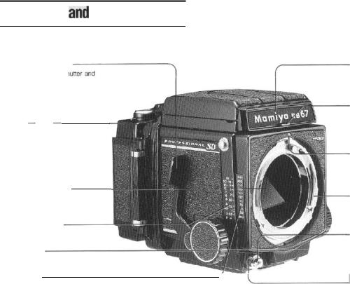

Coupling pin for film wind-stop release
When the shutter is released, the pin will automatically disengage film windstop allowing subsequent film advance.
Light baffle
DO NOT touch the baffle with your fingers!
Revolving adapter
Turning this adapter up to 90° permits change-over between the horizontal and vertical picture format.
R-lock lever
Use the lever to attach and detach the revolving adapter.
-Slide lock for G-lock type holder
Use the lock to attach and detach film holders. When the dark slide is not inserted in the attached roll film holder, a safety device prevents the holder from being detached from the camera body.
Coupling pin for multi-exposure prevention
Release lever for slide lock
When detaching a film holder other than the roll film holder, or when the slide lock is locked, move the slide lock to the left while pressing this release lever.
Tripod socket
The socket fits to a U 1/4-inch tripod screw. By removing the inner socket, a tripod with a 3/8-inch tripod screw can be used.
5
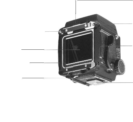
Back cover
Dark slide slot
Accepts the dark slide from either the right or left side.
Film spool stud
Load film so that th
pulled out following the guide marks.
Guide mark for leader paper
___________________
Starting mark
Wind the film advance lever until the leader paper staring mark is aligned with this mark. After closing the back cover, wind the lever several strokes, and it will stop at the first exposure position.
Film type index (120 or 220)
Exposure counter
When the film is advanced and the shutter is released, a red mark appears on the side of the counter digits. When the next film advance is completed, the red mark disappears. The red mark also appears while the film is being advanced from S to 1.
Multiple exposure lever
When multiple exposures are desired, simply move this lever to the front until
the red mark becomes visible.
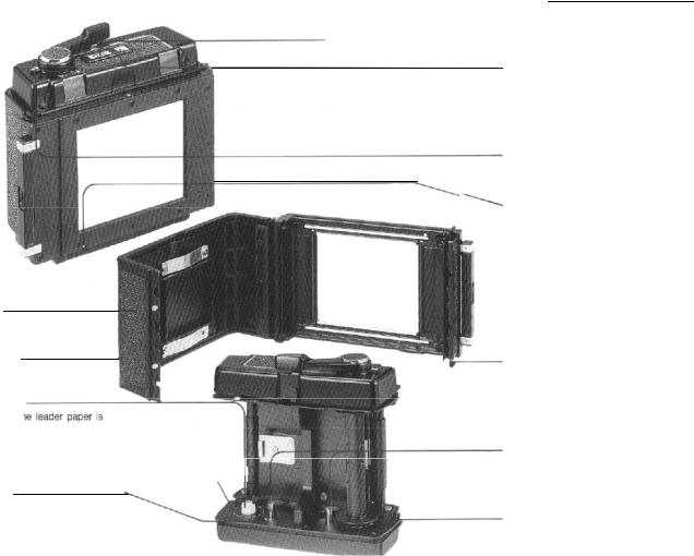
Pro-SD Outer cassette
Safety-catch for dark slide
When the film holder is being carried about after detaching it from the camera body, the safety device prevents the dark slide from accidentally slipping off.
When the film holder is attached to the camera body, the dark slide can be removed automatically.
Back cover latch (top and bottom)
To open back cover, both top and bottom latches must be pulled out.
Spool release pin
The film spool is attached and detached by pressing down this pin.
Take-up spool stud
After inserting the take-up spool, the leader paper is inserted in the spool.
7
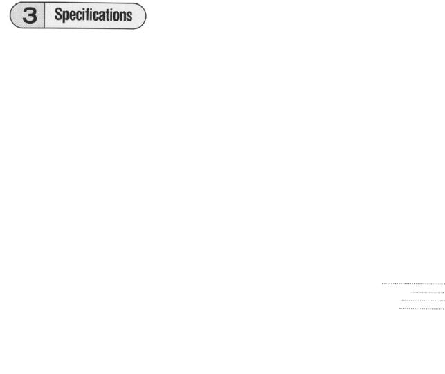
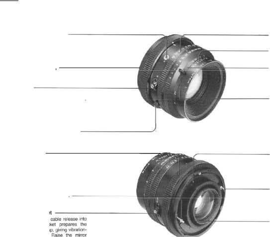
4 . Attaching and Removing the Lens
After cocking the mirror and the lens shutter, mount the lens on the camera body.
Cocking the mirror
1.Remove the front body cap from the camera body.
2.Be sure that the mirror is in the cocked, down position in the camera body, shielding
the film plane from exposure to light.
If the mirror is up, cock the mirror by fully pushing down the shutter cocking lever toward the front of the camera.
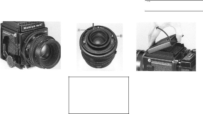
Cocking the lens shutter
1. Remove the rear cap of the lens by turning the bayonet ring clockwise.
2. Cock the lens shutter. Firmly turn the shutter cocking pins with your fingers, to the red dots (A) of the cocking position,
•If the cocking pins are not fully turned to the red dots (A), the shutter will not be completely cocked.
•The shutter is always cocked on a lens that has been removed from the body.
Attaching the lens
1.Turn the bayonet ring counterclockwise, and align the white dot on the bayonet ring with the red mark at the center of the lens mount.
2.Mount the lens, keeping the red mark aligned with the red mark on the body; then firmly twist the bayonet ring clockwise. The
camera and lens are now set.
NOTE:
Do not place the camera on its back without the rear body cap or film holder being in place. Otherwise the coupling mechanism may be damaged!
.
9
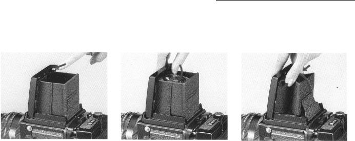
Operation
Raising the magnifier
Slide the magnifier release slightly to the left and the magnifier will pop up into position.
Lowering the magnifier
Gently push the base plate of the magnifier all the way down until it locks in place.
Folding the finder
After lowering the magnifier, gently squeeze the right and left panels of the finder together while closing it.
11
Loading...