

Page 1

B
XTM-XSM POWER UP 2007
ELECTRIC SYSTEM
TROUBLESHOOTING
WORKSHOP MANUALS
Page 2

B
08.06 3
Introduction
CHAPTER
PAGEISSUE
ELECTRIC SYSTEM TROUBLESHOOTING
ENGLISH
SECTION 1
B - TROUBLESHOOTING
B ELECTRICAL SYSTEM TROUBLESHOOTING
INTRODUCTION............................................................................................................................................... 4
Manual updates................................................................................................................................ 4
Notes for easy consultation .............................................................................................................. 4
Page layout ...................................................................................................................................... 4
Modified pages ................................................................................................................................. 5
Additional pages............................................................................................................................... 5
Editing symbols................................................................................................................................ 5
Abbreviations .................................................................................................................................... 7
TROUBLESHOOTING ...................................................................................................................................... 8
Wiring diagram ................................................................................................................................. 8
Key to general wiring diagram .......................................................................................................... 9
Colour key........................................................................................................................................ 9
Key to electrical components ......................................................................................................... 10
Connector test............................................................................................................................... 1 1
Switch tests .................................................................................................................................. 12
Connection of the switches described in this manual ..................................................................... 12
Key to ignition system................................................................................................................... 13
Troubleshooting ............................................................................................................................. 14
Recharging system key................................................................................................................. 18
Troubleshooting ............................................................................................................................. 19
Lighting system key ...................................................................................................................... 21
Troubleshooting ............................................................................................................................. 22
Lighting system check .................................................................................................................. 24
Signalling system key ................................................................................................................... 29
Troubleshooting ............................................................................................................................. 30
Signalling system check ............................................................................................................... 32
Page 3

B
4 08.06
Introduction
CHAPTER
PAGE ISSUE
ELECTRIC SYSTEM TROUBLESHOOTING
ENGLISH
SECTION 1
B - TROUBLESHOOTING
FIRST EDITION: 08/06
Y Chapter
X Section title
W Page N°
Z Date of issue
•MALAGUTI reserves the right to make any and all changes to its vehicles as it deems fit and appropriate at
any time without prior notice.
•No part of this publication, whether text or illustrations, may be reproduced or circulated. MALAGUTI
reserves all rights over this publication. Reasons must be given for any request for permission (written) thereto.
INTRODUCTION
•This publication describes all necessary steps for troubleshooting concerning the electrical system (of the
models indicated on the front page) and of the possible service operations, which are necessary for their
solution. It supplies the trade technicians (Authorised Service Centres) with the necessary information for
operating in compliance with the modern concepts of “good practice” and “safety at work”
•Further information can be derived from the “Chassis” workshop manual, from the “Engine” workshop
manual and from the Spare Parts catalogue.
•All described operations must be performed by technicians with the necessary skill and experience.
•The steps for the removal of body parts and of electric and mechanical components, to allow access to wiring
or electric components to service, can be taken from the Chassis Workshop Manual.
•We recommend you follow the information given in this publication with care.
•For any further information you may need, refer to the MALAGUTI Service Centre.
MANUAL UPDATES
•Updated pages of this publication will be delivered by us (in a reasonable time) already punched and therefore
ready to be incorporated in the Manual. The superseded sheets should not be removed from the manual as they
remain applicable to the servicing of pre-modified models.
•The table of contents will be duly updated in the event that new pages are inserted, which render the consultation
of the manual difficult.
•IMPORTANT! The Electrical System Troubleshooting Manual is to be considered as an essential tool to be
properly kept up-to-date so as to maintain its “validity” over time.
NOTES FOR EASY CONSULTATION
P AGE LA YOUT
Page 4

B
08.06 5
Introduction
CHAPTER
PAGEISSUE
ELECTRIC SYSTEM TROUBLESHOOTING
ENGLISH
SECTION 1
B - TROUBLESHOOTING
W
Z
Y
X
MODIFIED PAGES
•Modified pages shall bear the same number as those in the previous edition /pre-modified ones,
followed by the letter M, with the new date of issue appearing in the appropriate box.
•Modified pages may contain new illustrations; in this case, the added illustration (or illustrations) will bear the
number of the illustration on the former page, followed by a letter.
ADDITIONAL P AGES
•Any additional pages shall bear the last number of the section to which they belong, followed by the letter A and
the new date of issue.
EDITING SYMBOLS
•Symbols have been provided for quick and easy reference (see page 6), identifying situations requiring
utmost attention or providing practical suggestions or simple information.
•These symbols may appear next to a text (in which case they refer solely to the text itself), next to a figure
(in which case they refer to the topic illustrated in the figure and to the relative text), or at the top of the page
(in which case they refer to all the topics dealt with in the page).
Note:
The meaning of the symbols should be duly memorised as their scope is to avoid having to repeat basic
technical concepts or safety recommendations. They are therefore to be considered as veritable “memory
tags”. In case of any doubt as to their meaning, consult the page in which they are fully described.
P AGE DX
Page 5

B
6 08.06
Introduction
CHAPTER
PAGE ISSUE
ELECTRIC SYSTEM TROUBLESHOOTING
ENGLISH
SECTION 1
B - TROUBLESHOOTING
R
M
L
H
F
A
B
D
C
I
G
E
A) CAUTION! Recommendations and precautions regarding rider
safety and motor vehicle integrity
.
B) WARNING! Situations entailing the risk of personal injury to
maintenance or repair mechanics, other workshop personnel or
third parties, or damage to environment, vehicle or equipment.
C) FIRE HAZARD
Indicates operations which may constitute a fire hazard.
D) RISK OF EXPLOSION Indicates operations which may
constitute a risk of explosion.
E ) TOXIC FUMES
Indicates a possibility of intoxication or inflammation of the upper
respiratory tract.
F) MECHANICAL MAINTENANCE Operations to be performed only
by an expert mechanic.
G) ELECTRICAL MAINTENANCE
Operations be performed only by an expert electrical/electronic
technician
H) NO! Operations to be absolutely avoided
I) ENGINE SERVICE MANUAL Indicates information which may
be obtained by referring to said manual.
L) SPARE P ARTS CA T ALOGUE
Indicates information which may be obtained by referring to said
catalogue
Page 6

B
08.06 7
Introduction
CHAPTER
PAGEISSUE
ELECTRIC SYSTEM TROUBLESHOOTING
ENGLISH
SECTION 1
B - TROUBLESHOOTING
F4
A
F Figure
Cs Tightening torque
P Page
Pr Paragraph
S Section
Sc Diagram
T Table
V Screw
ABBREVIATIONS
Note:
the letter V in the illustrations refers to retaining or adjusting screws. The number following this letter refers to
the number of the same type of screw in the unit or component described and illustrated. Letters not followed
by a number indicate a single screw. In case of different screws being referred to in the illustration, the letter
V is followed by a number and a small letter, for instance: (V4a).
Unless otherwise specified, units and components are reassembled by proceeding in the reverse order of
removal.
Before any servicing, make sure that the vehicle is perfectly stable.
The front wheel should preferably be anchored to the equipment (A - F. 4) integral with the lif ting board.
Page 7

B
8 08.06
CHAPTER
PAGE
ELECTRIC SYSTEM TROUBLESHOOTING
ENGLISH
SECTION 2
Electrical System
SECTION 2
B - TROUBLESHOOTING
EDIZIONE
M
BL
AR
BL
BB
N
M
VR
VL
AR
N
M
VR
VL
GR
N
K A
B
R
+
-
N
LOCK
OFF
ON
VR
GR
VL
M-N
GL-R
GR-R
vuoto
vuoto
vuoto
1
18
LUCI
BL
VR-N
VR
GL
AR
VL-GL
RS
BL-R
BL-R
N
R
VL-GL
GL-R
B
BL-B
B-R
MODE
R
ENGINE
STOP
ON
OFF
ON
OFF
BL
R
10W
ID
SX
VL
10W
ID
DX
N
VR
35W
FARO
10W
ID
SX
N
VL
10W
ID
DX
N
VR
N
21W
STOP
5W
POS
RS
R
AR
HT
1
16
+
ON
OFF
HORN
GR
R
L
VL
M
VR
TURN
N
+
+
N
RS
F 10A
N
GL-R
Vuoto
BL
GR-R
GL-B
AR
B-R
Vuoto
BL-B
GL-VR
BL-N
M-N
RS-N
/ /
BL
R
R-N
N
GR
M-N
B-R
RS-N
B-R
BL-N
GL-VR
B-R
VL-GL
B
R
N
VL-GL
B
R
N
vuoto
vuoto
B-R
BL
VR/N
VR
GL
AR
vuoto
vuoto
R
B
N
B
BL-B
B-R
B-R
N
N
VL-GL
BL-R
B-N
N
VR-N
B-VR
N
GR
M
GR
VR-N
B-VR
B-N
N
BL
BL
BL
Vuoto
BL
B-GL
TPS
B-VL
R-N
B-VL
R-N
R-N
1
2
3
4
5
6 7
8
9
10
11
12
13
14
15
18
19
20
21
22
23
24
25
26
27
28
29
30
31
16
17
WIRING DIAGRAM
Page 8

B
08.06 9
CHAPTER
PAGEISSUE
ELECTRIC SYSTEM TROUBLESHOOTING
ENGLISH
SECTION 2
Electrical System
SECTION 2
B - TROUBLESHOOTING
KEY TO GENERAL WIRING DIAGRAM
1) BA TTERY
2) 10 A FUSE
3) CONTROL UNIT
4) FL YWHEEL MAGNETO
5) HORN
6) CHASSIS GROUNDING
7) FLASHLIGHT
8) TURN INDICA TOR BUTTON
9) HORN BUTTON
10) FRONT LEFT TURN INDICATO R
11 ) LOW BEAM / HIGH BEAM LIGHT
12) FRONT RIGHT TURN INDICA TOR
13) INSTRUMENT BOARD
14 ) KEY SWITCH
15) “MODE” BUTTON
16) “ENGINE STOP” BUTTON
17) FRONT STOP SWITCH
18) SOLENOID
19) REGULATOR
20) COIL
21 ) MIXER OIL PROBE
22 ) FUEL PROBE
23) REAR RIGHT TURN INDICAT OR
24 ) TAIL AND STOP LIGHT
25) REAR LEFT TURN INDICAT OR
26) GROUND
27 ) SIDE ST AND SWITCH
28 ) REAR STOP SWITCH
29 ) SPEEDOMETER SENSOR
30 ) WA TER TEMPERA TURE SENSOR
31 ) AIR TEMPERA TURE SENSOR
COLOUR KEY
This table lists the abbreviations used to identify the colour of the electrical connection cables on the wiring
diagram.
Abbreviations are given on the diagram, near the component
AR
AZ
B
BL
GL
GR
M
N
R
RS
VL
VR
AZ-B
B-M
B-N
B-R
B-VL
B-VR
BL-B
BL-GL
BL-N
BL-R
GL-B
GL-N
GL-R
GL-VR
GR-R
M-N
R-N
RS-N
VL-GL
VR-N
Orange
Light blue
White
Blue
Yellow
Grey
Brown
Black
Red
Pink
Purple
Green
Light blue White
White Brown
White Black
White Red
White Purple
White Green
Blue White
Blue Y ellow
Blue Black
Blue Red
Y ellow White
Yellow Black
Y ellow Red
Y ellow Green
Grey Red
Brown Black
Red Black
Pink Black
Purple Y ellow
Green Black
Page 9

B
10 08.06
CHAPTER
PAGE ISSUE
ELECTRIC SYSTEM TROUBLESHOOTING
ENGLISH
SECTION 2
Electrical Components
SECTION 2
B - TROUBLESHOOTING
1
2
3
4
5
6
7
8
910111213
14
15
16
17
KEY TO ELECTRICAL COMPONENTS
1) FRONT STOP SWITCH
2) REGULA T OR
3) CONTROL UNIT
4) 10 A FUSE
5) BA TTERY
6) FLASHLIGHT
7) SIDE ST AND SWITCH
8) COIL
9) REAR STOP SWITCH
10 ) MIXER OIL PROBE
1 1 ) SOLENOID
12 ) FUEL PROBE
13) H2O TEMPERATURE SENSOR
14) HORN
15) DIGITAL INSTRUMENT BOARD
16 ) KEY SWITCH
17 ) AIR TEMPERA TURE SENSOR
Page 10
B
08.06 11
CHAPTER
PAGEISSUE
ELECTRIC SYSTEM TROUBLESHOOTING
ENGLISH
SECTION 2
Checking the Connections
SECTION 2
B - TROUBLESHOOTING
A
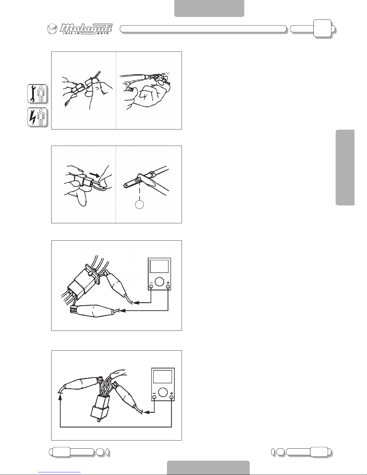
CHECKING CONNECTORS
Check connectors for corrosion and damp.
1. Disconnect
connectors
2. Dry terminals with compressed air .
3. Connect and disconnect connector two or
three times.
4. Pull connector to make sure it is correctly
plugged in.
5. If terminal comes loose, bend stop (A) and
refit terminal in connector.
6. Connect
connectors
NOTE:
The “click” sound means that all
connector parts are correctly assembled.
7. Check continuity with a Tester.
NOTE:
If there is no continuity, clean terminals.
Follow the instructions from step 1 to 7 to
check the electrical equipment.
As a temporary solution, use a contact
cleaner.
Use Tester as shown in the illustration.
Page 11

B
12 08.06
CHAPTER
PAGE ISSUE
ELECTRIC SYSTEM TROUBLESHOOTING
ENGLISH
SECTION 2
Checking the Switches
SECTION 2
B - TROUBLESHOOTING
CHECKING SWITCHES
Use a Tester to check continuity between terminals
and make sure these are correctly connected. If one of
the combinations does not give the requested result,
replace the component.
NOTE:
Operate the “ON-OFF” switch several times.
Put T ester selector on “W”.
Put indicator on “0”.
CONNECTION OF THE SWITCHES
DESCRIBED IN THIS MANUAL
This manual contains connection diagrams, like the one
illustrated on the left, which illustrate how switch
terminals should be connected (key switch, brake
switch, light switch, etc.).
The column on the left indicates the different positions
of the switches; the first line indicates the colours of
the wires connected to the switch terminals.
“•” means that there is continuity between the terminals;
namely a closed circuit in a certain position of the switch.
In this example, there is continuity between “Br” and
“R” when the switch is “ON”.
Page 12

B
08.06 13
CHAPTER
PAGEISSUE
ELECTRIC SYSTEM TROUBLESHOOTING
ENGLISH
SECTION 2
Ignition System
SECTION 2
B - TROUBLESHOOTING
M
BL
AR
BL
BB
N
M
VR
VL
AR
N
M
VR
VL
GR
N
K
A
B
R
+
-
N
LOCK
OFF
ON
VR
GR
VL
M-N
GL-R
GR-R
vuoto
vuoto
vuoto
1
18
LUCI
BL
VR-N
VR
GL
AR
VL-GL
RS
BL-R
BL-R
N
R
VL-GL
GL-R
B
BL-B
B-R
MODE
R
ENGINE
STOP
ON
OFF
ON
OFF
BL
R
10W
ID
SX
VL
10W
ID
DX
N
VR
35W
FARO
10W
ID
SX
N
VL
10W
ID
DX
N
VR
N
21W
STOP
5W
POS
RS
R
AR
HT
1
16
+
ON
OFF
HORN
GR
R
L
VL
M
VR
TURN
N
+
+
N
RS
F 10A
N
GL-R
Vuoto
BL
GR-R
GL-B
AR
B-R
Vuoto
BL-B
GL-VR
BL-N
M-N
RS-N
//
BL
R
R-N
N
GR
M-N
B-R
RS-N
B-R
BL-N
GL-VR
B-R
VL-GL
B
R
N
VL-GL
B
R
N
vuoto
vuoto
B-R
BL
VR/N
VR
GL
AR
vuoto
vuoto
R
B
N
B
BL-B
B-R
B-R
N
N
VL-GL
BL-R
B-N
N
VR-N
B-VR
N
GR
M
GR
VR-N
B-VR
B-N
N
BL
BL
BL
Vuoto
BL
B-GL
TPS
B-VL
R-N
B-VL
R-N
R-N
Vuoto
3
4
6
14
20
27
16
KEY TO IGNITION SYSTEM
3) CONTROL UNIT
4) FL YWHEEL MAGNETO
6) CHASSIS GROUNDING
14 ) KEY SWITCH
16) “ENGINE STOP” BUTTON
20) COIL
27 ) SIDE ST AND SWITCH
Page 13

B
14 08.06
CHAPTER
PAGE ISSUE
ELECTRIC SYSTEM TROUBLESHOOTING
ENGLISH
SECTION 2
Ignition System
SECTION 2
B - TROUBLESHOOTING
TROUBLESHOOTING
THE IGNITION SYSTEM DOES NOT WORK
(NO SPARKING OR INTERMITTENT SP ARKING)
1. Spark plug
2. Spark plug cap resistance
3. HV coil resistance
4. “ENGINE STOP” button
5. Side stand switch
6. Key switch
7. Pick-up resistance
8. System connections
1. Spark plug
- Check condition of spark plug
- Check type of spark plug
Gap between electrodes:
0.7 mm
COMPLIANT
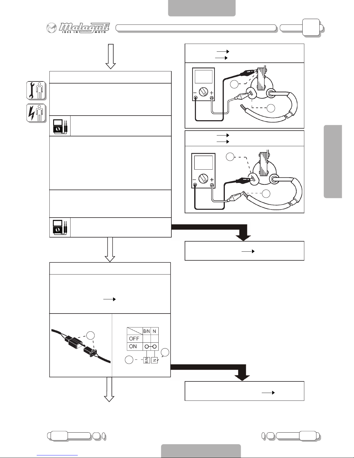
2. Spark plug cap resistance
- Remove spark plug cap
NOTE
Never pull spark plug cable to remove cap
- Connect the T ester (K
) as shown in the figure
T o remove, turn anti-clockwise
To connect, turn clockwise
- When connecting, check spark plug cable and
if necessary replace it with a new one.
Cap resistance:
5K
± 20% a 20°C
COMPLIANT
Sample spark plug:
NGK BR9ES
Spark plug not in working order Replace or
adjust gap between electrodes
NOT COMPLIANT
T erminal (+) Spark plug side (1)
T erminal (-) Spark plug cable side (2)
2
1
Faulty spark plug cap Replace
NOT COMPLIANT
Page 14
B
08.06 15
CHAPTER
PAGEISSUE
ELECTRIC SYSTEM TROUBLESHOOTING
ENGLISH
SECTION 2
Ignition System
SECTION 2
B - TROUBLESHOOTING
3. HV coil resistance
- Disconnect orange cable
- Connect T ester “
” to HV coil
- Check resistance of coil’s primary winding
Primary winding resistance:
0,23
± 20% a 20°C
- Connect Tester “
” to HV coil
- Check resistance of coil’s secondary winding
Primary winding resistance:
7,9
± 20% a 20°C
COMPLIANT
1
2
3
4. “Engine Stop” button
- Disconnect four-way connector (1)
- Connect Tester “
” and check continuity
between cables
White-black cable (2) Black cable (3)
See “Checking connectors” on page 1 1
COMPLIANT
T erminal (+) T erminal (1)
T erminal (-) Grounded (2)
1
2
1
2
T erminal (+) Spark plug cable (1)
T erminal (-) T erminal (2)
NOT COMPLIANT
Faulty HV coil Replace
NOT COMPLIANT
Faulty “Engine Stop” button Replace
Page 15

B
16 08.06
CHAPTER
PAGE ISSUE
ELECTRIC SYSTEM TROUBLESHOOTING
ENGLISH
SECTION 2
Ignition System
SECTION 2
B - TROUBLESHOOTING
5. Side stand switch
- Disconnect two-way connector (1) of side stand
- Connect T ester “
” to connector, as follows:
T erminal (+) T erminal (2)
T erminal (-) T erminal (3)
1
3
2
COMPLIANT
6. Key switch
- Disconnect connector (1) of key switch
- Turn key “ON”
- Connect Tester “
” and check continuity as
follows:
T erminal (+) Orange cable (2)
T erminal (-) Green cable (3)
See “Checking connectors” on page 1 1
1
2
3
COMPLIANT
NOT COMPLIANT
Faulty side stand switch Replace
NOT COMPLIANT
Faulty key switch Replace
Page 16

B
08.06 17
CHAPTER
PAGEISSUE
ELECTRIC SYSTEM TROUBLESHOOTING
ENGLISH
SECTION 2
Ignition System
SECTION 2
B - TROUBLESHOOTING
7. Pick-up resistance
- Disconnect four-way connector (1) of flywheel
magneto (2)
- Connect T ester “
” to connector, as follows:
T erminal (+) White-Red T erminal (3)
T erminal (-) Blue-White T erminal (4)
- Check pick-up resistance
Pick-up resistance:
350
± 20% a 20°C
COMPLIANT
8. Connections
- Check connections of ignition system
See “Circuit Diagram”.
COMPLIANT
Replace “CDI” control unit
1
4
3
2
NOT COMPLIANT
Replace stator
NOT COMPLIANT
Resume system’s connections
Page 17

B
18 08.06
CHAPTER
ISSUE
ELECTRIC SYSTEM TROUBLESHOOTING
ENGLISH
SECTION 2
Charging System
SECTION 2
B - TROUBLESHOOTING
PAGINA
M
BL
AR
BL
BB
N
M
VR
VL
AR
N
M
VR
VL
GR
N
K
A
B
R
+
-
N
LOCK
OFF
ON
VR
GR
VL
M-N
GL-R
GR-R
vuoto
vuoto
vuoto
1
18
LUCI
BL
VR-N
VR
GL
AR
VL-GL
RS
BL-R
BL-R
N
R
VL-GL
GL-R
B
BL-B
B-R
MODE
R
ENGINE
STOP
ON
OFF
ON
OFF
BL
R
10W
ID
SX
VL
10W
ID
DX
N
VR
35W
FARO
10W
ID
SX
N
VL
10W
ID
DX
N
VR
N
21W
STOP
5W
POS
RS
R
AR
HT
1
16
+
ON
OFF
HORN
GR
R
L
VL
M
VR
TURN
N
+
+
N
RS
F 10A
N
GL-R
Vuoto
BL
GR-R
GL-B
AR
B-R
Vuoto
BL-B
GL-VR
BL-N
M-N
RS-N
//
BL
R
R-N
N
GR
M-N
B-R
RS-N
B-R
BL-N
GL-VR
B-R
VL-GL
B
R
N
VL-GL
B
R
N
vuoto
vuoto
B-R
BL
VR/N
VR
GL
AR
vuoto
vuoto
R
B
N
B
BL-B
B-R
B-R
N
N
VL-GL
BL-R
B-N
N
VR-N
B-VR
N
GR
M
GR
VR-N
B-VR
B-N
N
BL
BL
BL
Vuoto
BL
B-GL
TPS
B-VL
R-N
B-VL
R-N
R-N
Vuoto
1
2
19
4
14
RECHARGING SYSTEM KEY
1) BA TTERY
2) 10 A FUSE
4) FL YWHEEL MAGNETO
14 ) KEY SWITCH
19) REGULATOR
Page 18

B
08.06 19
CHAPTER
PAGEISSUE
ELECTRIC SYSTEM TROUBLESHOOTING
ENGLISH
SECTION 2
Charging System
SECTION 2
B - TROUBLESHOOTING
TROUBLESHOOTING
IF BATTER Y IS FLA T
1. 10A fuse
2. Battery
3. Charging voltage
4. Charging coil resistance
5. Connections of charging system
1. 10 A fuse
- Remove fuse
- Connect Tester “
” to fuse
- Check continuity of fuse
2. Battery
- Check condition of battery
- Minimum voltage: 12.5 V
- Density of electrolytic solution: 1280 g/dm
3
- Level of electrolytic solution
3. Charging voltage
- Connect inductive rev counter to spark plug
cable
- Connect T ester (20 V DC) to battery.
T erminal (+) Terminal (+) of battery
T erminal (-) Terminal (-) of battery
- Measure battery voltage
- Run engine at 5000 RPM
- Check battery voltage
Charging voltage:
12.5 ~ 14.5 V
NOTE: Use a fully charged battery
NO CONTINUITY
Faulty fuse Replace
COMPLIANT
NOT COMPLIANT
- Clean terminals
- Recharge or replace battery
- T op up with distilled water
COMPLIANT
Recharging circuit is in working order
CONTINUITY
NOT COMPLIANT
Page 19

B
20 08.06
CHAPTER
ISSUE
ELECTRIC SYSTEM TROUBLESHOOTING
ENGLISH
SECTION 2
Charging System
SECTION 2
B - TROUBLESHOOTING
PAGINA
4. Charging coil resistance
- Disconnect four-way connector (1) of flywheel
magneto (2)
- Connect T ester “
” to connector, as follows:
T erminal (+) White cable terminal (3)
T erminal (-) Grounded (4)
- Measure resistance of charging coil
Charging coil resistance:
0.80
± 20% a 20°C
5. Recharging system connections
- Check connections of recharging system
See “Circuit Diagram”.
Replace voltage regulator
COMPLIANT
COMPLIANT
NOT COMPLIANT
Replace stator
NOT COMPLIANT
Resume system’s connections
1
2
3
4
Page 20

B
08.06 21
CHAPTER
PAGEISSUE
ELECTRIC SYSTEM TROUBLESHOOTING
ENGLISH
SECTION 2
Lighting System
SECTION 2
B - TROUBLESHOOTING
M
BL
AR
BL
BB
N
M
VR
VL
AR
N
M
VR
VL
GR
N
K
A
B
R
+
-
N
LOCK
OFF
ON
VR
GR
VL
M-N
GL-R
GR-R
vuoto
vuoto
vuoto
1
18
LUCI
BL
VR-N
VR
GL
AR
VL-GL
RS
BL-R
BL-R
N
R
VL-GL
GL-R
B
BL-B
B-R
MODE
R
ENGINE
STOP
ON
OFF
ON
OFF
BL
R
10W
ID
SX
VL
10W
ID
DX
N
VR
35W
FARO
10W
ID
SX
N
VL
10W
ID
DX
N
VR
N
21W
STOP
5W
POS
RS
R
AR
HT
1
16
+
ON
OFF
HORN
GR
R
L
VL
M
VR
TURN
N
+
+
N
RS
F 10A
N
GL-R
Vuoto
BL
GR-R
GL-B
AR
B-R
Vuoto
BL-B
GL-VR
BL-N
M-N
RS-N
//
BL
R
R-N
N
GR
M-N
B-R
RS-N
B-R
BL-N
GL-VR
B-R
VL-GL
B
R
N
VL-GL
B
R
N
vuoto
vuoto
B-R
BL
VR/N
VR
GL
AR
vuoto
vuoto
R
B
N
B
BL-B
B-R
B-R
N
N
VL-GL
BL-R
B-N
N
VR-N
B-VR
N
GR
M
GR
VR-N
B-VR
B-N
N
BL
BL
BL
Vuoto
BL
B-GL
TPS
B-VL
R-N
B-VL
R-N
R-N
Vuoto
11
24
19
4
14
LIGHTING SYSTEM KEY
4) FL YWHEEL MAGNETO
11) LOW BEAM / HIGH BEAM LIGHT
14 ) KEY SWITCH
19) REGULATOR
24) TAIL AND STOP LIGHT
Page 21

B
22 08.06
CHAPTER
PAGE ISSUE
ELECTRIC SYSTEM TROUBLESHOOTING
ENGLISH
SECTION 2
Lighting System
SECTION 2
B - TROUBLESHOOTING
1
2
3
4
TROUBLESHOOTING
HEADLIGHT , T AIL LIGHT
AND INSTRUMENT BOARD LIGHTS DO NOT COME ON
1. Lighting system coil resistance
2. Continuity of Purple-Y ellow cable
3. Key switch
4. Connection of lighting system
1. Lighting system coil resistance
- Disconnect four-way connector (1) of flywheel
magneto (2)
- Connect T ester “” to connector, as follows:
T erminal (+)
Y ellow-red cable terminal (3)
T erminal (-)
Grounded (4)
- Measure resistance of lighting system coil
Charging coil resistance:
0.80
± 20% a 20°C
COMPLIANT
NOT COMPLIANT
Replace stator
Page 22

B
08.06 23
CHAPTER
PAGEISSUE
ELECTRIC SYSTEM TROUBLESHOOTING
ENGLISH
SECTION 2
Troubleshooting
SECTION 2
B - TROUBLESHOOTING
1
2
3
2. Check continuity of purple-yellow cable
- Disconnect regulator connector
- Disconnect four-way connector of flywheel
magneto
- Connect T ester “” between purple-yellow cable
of flywheel connector (system side) and pink
cable of regulator connector.
CONTINUITY
3. Key switch
- Disconnect connector (1) of key switch
- Turn key “ON”
- Connect Tester “” and check continuity as
follows:
T erminal (+) Yellow cable (2)
T erminal (-) Green-black cable (3)
See “Checking connectors” on page 11
COMPLIANT
4. Connections
- Check all connections to lighting system
See “Circuit diagram”
COMPLIANT
Replace voltage regulator
NO CONTINUITY
Purple-yellow cable interrupted: resume connection
See “Circuit Diagram”
NOT COMPLIANT
NOT COMPLIANT
Resume system’s connections
Faulty key switch Replace
Page 23

B
24 08.06
CHAPTER
PAGE ISSUE
ELECTRIC SYSTEM TROUBLESHOOTING
ENGLISH
SECTION 2
Lighting System
SECTION 2
B - TROUBLESHOOTING
CHECKING LIGHTING SYSTEM
THE HEADLIGHT DOES NOT COME ON
CONTINUITY
1. Light bulb and relative coupling
- Check continuity of light bulb and its coupling
2. Check lamp socket voltage
- Connect Tester “20V AC” to connector of
headlight
Terminal (+) Pink cable
Terminal (-) Black cable
- Run engine at approx. 5000 RPM
- Power measured must be 12.5V
COMPLIANT
Circuit is in working order
NO CONTINUITY
Replace lamp or coupling
NOT COMPLIANT
Resume connections of headlight
See “Circuit Diagram”
Page 24

B
08.06 25
CHAPTER
PAGEISSUE
ELECTRIC SYSTEM TROUBLESHOOTING
ENGLISH
SECTION 2
Lighting System
SECTION 2
B - TROUBLESHOOTING
REAR LIGHT DOES NOT COME ON.
1. Light bulb and relative coupling
- Check continuity of light bulb and its coupling
CONTINUITY
2. Check lamp socket voltage
- Connect T ester “20V AC” to terminals of light bulb
coupling
T erminal (+) Pink cable terminal
T erminal (-) Black cable terminal
- Run engine at approx. 5000 RPM
- Power measured must be 12.5V
COMPLIANT
Circuit is in working order
NO CONTINUITY
Replace lamp or coupling
NOT COMPLIANT
Resume connections between key switch and rear
light
See “Circuit Diagram”
Page 25

B
26 08.06
CHAPTER
PAGE ISSUE
ELECTRIC SYSTEM TROUBLESHOOTING
ENGLISH
SECTION 2
Lighting System
SECTION 2
B - TROUBLESHOOTING
LOW BEAM LIGHT DOES NOT COME ON
(SWITZERLAND VERSION ONLY)
1. Light bulb and relative coupling
- Check continuity of light bulb and its coupling
CONTINUITY
2. Check left switch
Connect Tester (
) to switch as follows:
- T ester (+) terminal white/blue cable
- T ester (-) terminal pink cable
- Turn switch light to “LO” symbol.
CONTINUITY
The white/blue cable leading from the left hand
switch to the lamp socket is interrupted. Repair,
see “Circuit Diagram”
NO CONTINUITY
Replace lamp or coupling
NO CONTINUITY
Replace left hand switch
HIGH BEAM LIGHT DOES NOT COME ON BUT HIGH BEAM INDICAT OR LIGHT DOES
(SWITZERLAND VERSION ONLY)
1. Light bulb and relative coupling
- Check continuity of light bulb and its
coupling
CONTINUITY
- Check continuity of blue cable leading from left
hand switch to lamp socket of headlight
NO CONTINUITY
Replace lamp or coupling
NO CONTINUITY
Blue cable interrupted.
Repair, (see “Circuit Diagram”).
Page 26

B
08.06 27
CHAPTER
PAGEISSUE
ELECTRIC SYSTEM TROUBLESHOOTING
ENGLISH
SECTION 2
Lighting System
SECTION 2
B - TROUBLESHOOTING
HIGH BEAM LIGHT AND INDICA TOR LIGHT ARE NOT WORKING
(SWITZERLAND VERSION ONLY)
1. Check left switch
Connect Tester (
) to switch as follows:
- T ester (+) terminal blue cable
- T ester (-) terminal pink cable
- Turn light switch to “HI” symbol.
NO CONTINUITY
Replace left hand switch
HIGH BEAM INDICAT OR LIGHT DOES NOT COME ON
(SWITZERLAND VERSION ONLY)
1. Light bulb and relative coupling
- Check continuity of light bulb and its coupling
- Check continuity of blue cable leading from left
hand switch to lamp socket of instrument board
indicator light
CONTINUITY
CONTINUITY
There is no lamp socket grounding point. Repair by
providing a jumper between black cable connected
to lamp socket and a grounded point of the chassis.
NO CONTINUITY
Replace lamp or coupling
Blue cable is interrupted
Repair, see “Circuit Diagram”
NO CONTINUITY
Page 27

B
28 08.06
CHAPTER
PAGE ISSUE
ELECTRIC SYSTEM TROUBLESHOOTING
ENGLISH
SECTION 2
Lighting System
SECTION 2
B - TROUBLESHOOTING
NUMBER PLA TE LIGHT DOES NOT COME ON
(SWITZERLAND VERSION ONLY)
1. Lamp and lamp socket
- Check continuity of lamp and lamp socket
CONTINUITY
2. Check continuity of pink cable
- Connect Tester (
) between pink cable of tail
light lamp socket and pink cable of number
plate light lamp socket.
- No continuity: pink cable is interrupted. Repair
(see wiring diagram).
NO CONTINUITY
Replace lamp and/or lamp socket
NO CONTINUITY
Pink cable is interrupted
Repair, see “Circuit Diagram”
CONTINUITY
- There is no lamp socket grounding point. Repair by
providing a jumper between black cable connected
to lamp socket and a grounded point of the chassis.
Page 28

B
08.06 29
CHAPTER
PAGEISSUE
ELECTRIC SYSTEM TROUBLESHOOTING
ENGLISH
SECTION 2
Signal System
SECTION 2
B - TROUBLESHOOTING
M
BL
AR
BL
BB
N
M
VR
VL
AR
N
M
VR
VL
GR
N
K
A
B
R
+
-
N
LOCK
OFF
ON
VR
GR
VL
M-N
GL-R
GR-R
vuoto
vuoto
vuoto
1
18
LUCI
BL
VR-N
VR
GL
AR
VL-GL
RS
BL-R
BL-R
N
R
VL-GL
GL-R
B
BL-B
B-R
MODE
R
ENGINE
STOP
ON
OFF
ON
OFF
BL
R
10W
ID
SX
VL
10W
ID
DX
N
VR
35W
FARO
10W
ID
SX
N
VL
10W
ID
DX
N
VR
N
21W
STOP
5W
POS
RS
R
AR
HT
1
16
+
ON
OFF
HORN
GR
R
L
VL
M
VR
TURN
N
+
+
N
RS
F 10A
N
GL-R
Vuoto
BL
GR-R
GL-B
AR
B-R
Vuoto
BL-B
GL-VR
BL-N
M-N
RS-N
//
BL
R
R-N
N
GR
M-N
B-R
RS-N
B-R
BL-N
GL-VR
B-R
VL-GL
B
R
N
VL-GL
B
R
N
vuoto
vuoto
B-R
BL
VR/N
VR
GL
AR
vuoto
vuoto
R
B
N
B
BL-B
B-R
B-R
N
N
VL-GL
BL-R
B-N
N
VR-N
B-VR
N
GR
M
GR
VR-N
B-VR
B-N
N
BL
BL
BL
Vuoto
BL
B-GL
TPS
B-VL
R-N
B-VL
R-N
R-N
Vuoto
24
14
1
2
3
5
7
8
9
10
12
13
15
21
22
23
25
26
28
29
30
31
17
SIGNALLING SYSTEM KEY
1) BA TTERY
2) 10 A FUSE
3) CONTROL UNIT
5) HORN
7) FLASHLIGHT
8) TURN INDICA TOR BUTTON
9) HORN BUTTON
10) FRONT LEFT TURN INDICAT OR
12) FRONT RIGHT TURN INDICA TOR
13) INSTRUMENT BOARD
14 ) KEY SWITCH
15) “MODE” BUTTON
17) FRONT STOP SWITCH
21) OIL INDICA TOR SWITCH
22 ) FUEL RESERVE SENSOR
23) REAR RIGHT TURN INDICATOR
24 ) TAIL AND STOP LIGHT
25) REAR LEFT TURN INDICATOR
26) GROUND
28 ) REAR STOP SWITCH
29 ) SPEEDOMETER SENSOR
30 ) WA TER TEMPERA TURE SENSOR
31 ) AIR TEMPERATURE SENSOR
Page 29

B
30 08.06
CHAPTER
PAGE ISSUE
ELECTRIC SYSTEM TROUBLESHOOTING
ENGLISH
SECTION 2
Lighting System
SECTION 2
B - TROUBLESHOOTING
TROUBLESHOOTING
TURN INDICA TORS, STOP LIGHT, NEUTRAL AND FUEL INDICA T OR LIGHTS DO NOT COME ON; REV
COUNTER AND HORN DO NOT WORK
Check
1. 10 A fuse
2. Battery
3. Key switch
4. Connections of signalling system
1. 10 A Fuse
- Remove fuse
- Connect T ester “” to fuse
- Check continuity of fuse
CONTINUITY
2. Battery
- Check condition of battery.
Minimum voltage: 12.5 V
Density of electrolytic solution:
1280 g/dm
3
Level of electrolytic solution
COMPLIANT
NO CONTINUITY
Faulty fuse Replace
NOT COMPLIANT
- Clean terminals
- Recharge or replace battery
- T op up with distilled water
Page 30

B
08.06 31
CHAPTER
PAGEISSUE
ELECTRIC SYSTEM TROUBLESHOOTING
ENGLISH
SECTION 2
Signal System
SECTION 2
B - TROUBLESHOOTING
1
2
3
3. Key switch
- Disconnect connector (1) of key switch
- Turn key “ON”
- Connect Tester “” and check continuity as
follows:
T erminal (+) Orange cable (2)
T erminal (-) Green cable (3)
See “Checking connectors” on page 11
COMPLIANT
4. Check connections
- Check connections of signalling system
See “Circuit Diagram”
NOT COMPLIANT
Faulty key switch Replace
NOT COMPLIANT
Resume system’s connections
Page 31

B
32 08.06
CHAPTER
PAGE ISSUE
ELECTRIC SYSTEM TROUBLESHOOTING
ENGLISH
SECTION 2
Lighting System
SECTION 2
B - TROUBLESHOOTING
CHECKING SIGNALLING SYSTEM
HORN IS NOT WORKING
1. Horn button
- Disconnect six-way connector of left hand switch
- Connect T ester “” to connector (1)
- Press Horn button to activate horn
- Check continuity as follows:
T erminal (+) Grey cable (2)
T erminal (-) Black cable (3)
Button pressed Continuity
Button not pressed No continuity
See “Checking connectors” on page 1 1
Comando SX
M
VR
VL
GR
N
+
ON
OFF
HORN
GR
R
L
VL
M
VR
TURN
N
+
+
/
1
2
3
COMPLIANT
2. Check voltage level
- Connect T ester (20V DC) to horn cables (1)
T erminal (+)
Blue cable (2)
T erminal (-)
Orange cable (3)
- Turn key “ON”
- Press Horn button to activate horn
-
Power measured must be 12.5 V
NOT COMPLIANT
NOT COMPLIANT
Faulty horn button
Replace left hand
switch
BL AR
1
3
2
COMPLIANT
Replace horn
Page 32

B
08.06 33
CHAPTER
PAGEISSUE
ELECTRIC SYSTEM TROUBLESHOOTING
ENGLISH
SECTION 2
Signal System
SECTION 2
B - TROUBLESHOOTING
3. Check blue cable power supply
- Connect T ester (20 V DC) to horn (1)
T erminal (+) Blue cable (2)
T erminal (-) Chassis grounding (3)
- Turn key “ON”
- Press Horn button to activate horn
- Power measured must be 12.5 V
BL AR
1
3
2
NOT COMPLIANT
Blue cable interrupted.
See “Circuit Diagram”
COMPLIANT
Resume connection of orange cable
See “Circuit Diagram”
Page 33

B
34 08.06
CHAPTER
PAGE ISSUE
ELECTRIC SYSTEM TROUBLESHOOTING
ENGLISH
SECTION 2
Signal System
SECTION 2
B - TROUBLESHOOTING
STOP LIGHT DOES NOT COME ON
1. Light bulb and relative coupling
- Check continuity of light bulb and its coupling
CONTINUITY
2. Front and rear brake switch
- Disconnect switch cables
- Connect T ester “” to terminals (T1-T2)
- Check continuity between terminals
See “Checking switches” on page 12
(A) Front brake switch
(B) Rear brake switch
A
B
1- Front brake lever
operated
2- Front brake lever
not operated
1- Rear brake pedal
pressed
2- Brake pedal not
pressed
COMPLIANT
NO CONTINUITY
Replace lamp or coupling
NOT COMPLIANT
Faulty brake switch Replace
Page 34

B
08.06 35
CHAPTER
PAGEISSUE
ELECTRIC SYSTEM TROUBLESHOOTING
ENGLISH
SECTION 2
Signal System
SECTION 2
B - TROUBLESHOOTING
3. Check voltage level
- Connect Tester (20V DC) to connector of light
bulb coupling
T erminal (+) Red cable (1)
T erminal (-) Black cable (2)
- Turn key “ON”
- Pull brake lever or press brake pedal
- Power measured in both cases must be 12.5V
1
2
COMPLIANT
Circuit is in working order
NOT COMPLIANT
Red cable interrupted; resume connection
See “Circuit Diagram”
Page 35

B
36 08.06
CHAPTER
PAGE ISSUE
ELECTRIC SYSTEM TROUBLESHOOTING
ENGLISH
SECTION 2
Signal System
SECTION 2
B - TROUBLESHOOTING
TURN INDICA TORS AND/OR TURN INDICA T OR LIGHTS ARE NOT WORKING
1. Light bulb and relative coupling
- Check continuity of light bulb and its coupling
CONTINUITY
2. Turn indicator switch
- Disconnect six-way connector of left hand switch
- Connect T ester “” to connector, as follows:
- Press switch to activate right hand turn indicators
T erminal (+) Brown cable (2)
T erminal (-) Green cable (3)
- Press switch to activate left hand turn indicators
T erminal (+) Brown cable (2)
T erminal (-) Purple cable (4)
- There must be continuity in both cases
M
VR
VL
AR
N
Comando SX
M
VR
VL
GR
N
+
ON
OFF
HORN
GR
R
L
VL
M
VR
TURN
N
+
+
//
1
3 2 4
COMPLIANT
NOT COMPLIANT
Replace lamp or coupling
NOT COMPLIANT
Faulty turn indicator switch Replace left
hand switch
Page 36

B
08.06 37
CHAPTER
PAGEISSUE
ELECTRIC SYSTEM TROUBLESHOOTING
ENGLISH
SECTION 2
Signal System
SECTION 2
B - TROUBLESHOOTING
3. Check voltage level of flashlight
- Disconnect flashlight connector (1)
- Connect T ester (20V DC) as follows:
T erminal (+) Blue cable (2)
T erminal (-) Chassis grounding cable (3)
1
- Turn key “ON”
- Power measured must be 12V
COMPLIANT
4. Check continuity of brown cable
- Disconnect flashlight connector
- Disconnect left hand switch connector
- Connect Tester “” to terminals of respective
connectors
- Check continuity of brown cable
CONTINUITY
Faulty flashlight Replace
NOT COMPLIANT
Blue cable between key switch and flashlight
interrupted. Resume connection
See “Circuit Diagram”
NO CONTINUITY
Brown cable between flashlight and left hand
switch interrupted. Resume connection
See “Circuit Diagram”
2
3
Page 37

B
38 08.06
CHAPTER
PAGE ISSUE
ELECTRIC SYSTEM TROUBLESHOOTING
ENGLISH
SECTION 2
Signal System
SECTION 2
B - TROUBLESHOOTING
5. Check voltage delivered to right hand and
left hand lamp sockets
- Connect T ester (20V DC) to connector of lamp
coupling
(A) Left hand turn indicator
T erminal (+) Purple cable (1)
T erminal (-) Chassis grounding cable
(B) Right hand turn indicator
T erminal (+) Green cable (2)
T erminal (-) Chassis grounding cable
1 2
- Turn key “ON”
- (A) operate the switch, to activate the left hand
turn indicators
- (B) operate the switch, to activate the right hand
turn indicators
- Power measured in both cases must be 12.5V
COMPLIANT
Circuit is in working order
NOT COMPLIANT
Cable interrupted between turn indicators and
connector of lamp coupling. Resume
connection.
See “Circuit Diagram”
Page 38

B
08.06 39
CHAPTER
PAGEISSUE
ELECTRIC SYSTEM TROUBLESHOOTING
ENGLISH
SECTION 2
Signal System
SECTION 2
B - TROUBLESHOOTING
B
R
CRUSCOTTO
VR
GR
VL
M-N
GL-R
GR-R
vuoto
vuoto
vuoto
1
18
vuoto
vuoto
N
VL-GL
BL-R
BL
R-N
NEUTRAL INDICATOR LIGHT DOES NOT COME ON
1. Check neutral switch
- Connect Tester “” and check continuity
between neutral switch and grounding point
Neutral switch (1) Grounding point (2)
Neutral Continuity
Vehicle in gear No continuity
COMPLIANT
2. Check instrument board
- Disconnect instrument board connector (1)
- Disconnect lead terminal (2) of neutral switch
- Connect T ester “”, as follows:
T erminal (+) Red-black lead terminal (2)
T erminal (-) Red-black cable (3)
CONTINUITY
Replace instrument board
NOT COMPLIANT
Faulty neutral switch Replace
WARNING
After removing the lead terminal, make sure
the neutral switch is firmly screwed in place.
NO CONTINUITY
Cable interrupted between neutral switch and
instrument board connector. Resume connection.
See “Circuit Diagram”
2
3
1
Page 39

B
40 08.06
CHAPTER
PAGE ISSUE
ELECTRIC SYSTEM TROUBLESHOOTING
ENGLISH
SECTION 2
Signal System
SECTION 2
B - TROUBLESHOOTING
Comando DX
MODE
ENGINE
STOP
ON
OFF
ON
OFF
B-N
N
VR-N
B-VR
VR-N
B-VR
B-N
N
WITH “MODE” BUTTON PRESSED, FUNCTIONS ON THE DISPLA Y CANNOT BE CHANGED
1. Check “Mode” button
- Disconnect six-way connector of right hand
switch (1)
- Connect T ester “”, as follows
T erminal (-) Green-black cable (2)
T erminal (-) White-green cable (3)
- Press the “Mode” button”
- Check continuity
See “Checking connectors” on page 1 1
2
3
1
CONTINUITY
2. Check power supply
- Disconnect six-way connector of right hand
switch (1)
- Connect T ester (20 V DC) to connector (system
side) as follows:
T erminal (+) Blue cable (2)
T erminal (-) Chassis grounding (3)
- Turn key “ON”
- Power measured must be 12.5V
Comando DX
MODE
ENGINE
STOP
ON
OFFONOFF
B-N
N
VR-N
B-VR
VR-N
B-VR
B-N
N
R
BL
B-VL
R-N
COMPLIANT
NO CONTINUITY
Faulty “Mode” button Replace right hand
switch
NOT COMPLIANT
“Mode” button is not powered; blue cable is
interrupted. Resume connection.
See “Circuit Diagram”
2
3
1
Page 40

B
08.06 41
CHAPTER
PAGEISSUE
ELECTRIC SYSTEM TROUBLESHOOTING
ENGLISH
SECTION 2
Signal System
SECTION 2
B - TROUBLESHOOTING
3. Check continuity of red cable
Connect T ester “” as follows:
T erminal (+) Red cable (3)
T erminal (-) Red cable (4)
Check continuity of red cable between connector of
right hand controls (1) and instrument board
connector (2)
Comando DX
MODE
ENGINE
STOP
ON
OFF
ON
OFF
B-N
N
VR-N
B-VR
VR-N
B-VR
B-N
N
R
BL
B-VL
R-N
B
R
CRUSCOTTO
VR
GR
VL
M-N
GL-R
GR-R
vuoto
vuoto
vuoto
1
18
vuoto
vuoto
N
VL-GL
BL-R
BL
R-N
2
1
4
3
CONTINUITY
Replace instrument board
NO CONTINUITY
Red cable interrupted.
Resume connection
See “Circuit Diagram”
Page 41

B
42 08.06
CHAPTER
PAGE ISSUE
ELECTRIC SYSTEM TROUBLESHOOTING
ENGLISH
SECTION 2
Signal System
SECTION 2
B - TROUBLESHOOTING
REV COUNTER IS NOT WORKING
- Connect T ester “” as follows
T erminal (+) Purple-yellow cable (3)
T erminal (-) Purple-yellow cable (4)
- Check continuity of purple-yellow cable
between flywheel magneto connector (1) and
instrument board connector (2)
1
3
2
4
CONTINUITY
Replace instrument board
NO CONTINUITY
Purple-yellow cable interrupted. Resume
connection.
See “Circuit Diagram”.
FAULTY FUEL INDICATOR
1. Check fuel probe
- Detach connector of fuel probe
- Provide jumper between grey cable and black
cable of connector on system side
- Turn key “ON” and wait a few seconds
LIGHT OFF
LIFT OFF
Replace fuel cock
Page 42

B
08.06 43
CHAPTER
PAGEISSUE
ELECTRIC SYSTEM TROUBLESHOOTING
ENGLISH
SECTION 2
Signal System
SECTION 2
B - TROUBLESHOOTING
2. Continuity of grey cable
- Connect Tester “” and check continuity of grey
cable between fuel probe connector and
instrument board connector (PIN 6)
CONTINUITY
3. Check grounding (black cable)
- Connect T ester “”, as follows:
Terminal (+) Black cable
T erminal (-) Chassis grounding
- Check continuity of grounding of probe
connector (black cable on system side)
CONTINUITY
Replace instrument board
NO CONTINUITY
Grey cable interrupted. Resume
connection.
See “Circuit Diagram”.
NO CONTINUITY
Black cable interrupted. Resume
connection.
See “Circuit Diagram”.
Page 43

B
44 08.06
CHAPTER
PAGE ISSUE
ELECTRIC SYSTEM TROUBLESHOOTING
ENGLISH
SECTION 2
Signal System
SECTION 2
B - TROUBLESHOOTING
FAULTY MIXTURE OIL INDICATOR
1. Check oil probe
- T ake oil probe out of tank, disconnect
connector and connect Tester in “”
- T ester (+) terminal
coupling 1
- T ester (-) terminal coupling 2
- Whilst keeping probe upright, float “A” must run
freely and position itself at the base of the probe:
continuity
- Overturn probe: no continuity
COMPLIANT
B ) Check continuity of grounding
of black cable plugged into probe
- Disconnect connector from probe and connect
tester “
” (F23).
- T ester (+) terminal Black cable (1)
- T ester (-) terminal Chassis grounding
(2)
CONTINUITY
White cable between probe and digital instrument
interrupted; repair.
See “Circuit Diagram”
NOT COMPLIANT
Replace oil probe
NO CONTINUITY
Black cable interrupted; repair by providing a
jumper between black cable and grounded point
of chassis.
1
2
Page 44

B
08.06 45
CHAPTER
PAGEISSUE
ELECTRIC SYSTEM TROUBLESHOOTING
ENGLISH
SECTION 2
Signal System
SECTION 2
B - TROUBLESHOOTING
CONFIGURA TION OF THE DIGITAL INSTRUMENT CONNECTOR
Pos. Meaning
1 GND
2 RH turn indicator
3 LH turn indicator
4 Wheel sensor input
5 Button
6 Fuel probe
7 N.C.
8 RPM
9 N.C.
Pos. Meaning
10 N.C.
11 N.C.
1 2 Mixture oil
13 T emperature probe
1 4 Key activation (+)
15 Neutral
1 6 Battery positive
17 Troubleshooting indicator light
18 N.C.
Pin-Out and drawing of
socket (cable insertion
side)
FUNCTION MAIN MENU
1. Current speed function
This information is always provided by the large 7segment digits at the centre of the display,
irrespective of the function selected or of any active
alarms. Current speed can be given in km/h or, if
the setup menu is accessed, in mph; the selected
mode is shown on the display, to the right of the
numeric value provided. The display is updated every
0.5 seconds.
Displ.
(cc)
50cc
50cc
The system’s size depends on the following parameters:
Model
Motard
Enduro
Circ.
(mm)
1.831
2.125
Pulse/
wheel turn
22
25
CT
(pulses/min.)
200.25
196.08
Max. sp.
(km/h)
160 km/h
(99 mph)
Overestimate
5% v < 45 km/h
15% v > 45 km/h
Resol.
1 km/h
(1 mph)
CT= pulses per minute that the instrument must receive to display 1 km/h in real time (no overestimate).
Current speed function (km/h)
Current speed function (mph)
Page 45

B
46 08.06
CHAPTER
PAGE ISSUE
ELECTRIC SYSTEM TROUBLESHOOTING
ENGLISH
SECTION 2
Signal System
SECTION 2
B - TROUBLESHOOTING
2. Acceleration function (0-40)
This function measures the time employed by the
vehicle to reach 40 km/h. This time is displayed by
the small digits. After reaching a speed of 40 km/h,
the message 0-40 (0-25 if you have selected mph)
is replaced by the time employed, which will remain
visible for 15 seconds.
When this time ends, the counter is reset and the
indication 0-40 reappears (0-25 if you have selected mph).
T o activate and/or reset this function, you must stop
the vehicle.
3. Time function (TIME)
The time function (TIME) displays the current time.
To activate it, scroll through the menu by pressing
the button until the relevant heading appears. When
the vehicle is at a standstill, you can adjust the
current time by holding the MODE button down until
only the segments of the time function and the
relative TIME heading are visible (this happens after
about 5 seconds).
Hold down the button to gradually increase the
minutes; after 10 of these increasing sessions,
adjustment switches to rapid hour increasing. To
return to slow minute increasing, release and press
the button again (max. time 3 sec).
After adjusting, release the button and wait (about
3 seconds) for the display to resume its initial
appearance. If the vehicle is started during
adjustment, the instrument will automatically switch
from time adjustment to the status in which it was
in before the time function was selected.
- Sequence displayed: from 0:00 to 23:59
- Current time information is not memorised.
- Accuracy of clock: ± 2.5"/day
Acceleration function
Time function (TIME)
TIME adjustment function
Page 46

B
08.06 47
CHAPTER
PAGEISSUE
ELECTRIC SYSTEM TROUBLESHOOTING
ENGLISH
SECTION 2
Signal System
SECTION 2
B - TROUBLESHOOTING
4. Chronometer function (LAP)
The information is displayed by the small digits,
accompanied by the heading LAP that identifies
the function displayed. Being the menu controlled
by a single button, when the function is activated,
the last countdown is displayed; press the button
to reset the counter. The counter will thus start
counting up until the button is pressed again. When
the button is pressed, counting ends and you can
read the relative information. T o switch to the next
function, press the button again. These functions
can be activated either with the vehicle halted or
running.
- Display range: from 00’00’’ to 59’59’’
- Counter resolution: 1 sec.
5. Average speed function (AVE)
The information is displayed by the small digits,
accompanied by the heading AVE. After selecting
AVE, you can reset the counter by holding the
button down until you display 0.0 (this takes about
3 seconds).
The counter can be reset either with the vehicle
halted or running. A verage speed is calculated as
the relation between the distance travelled and the
time employed to cover this distance (measured in
seconds); the information is acquired in km/h or
mph, depending on the unit of measurement
selected, with a resolution of 1 decimal unit.
Calculation of this time function is based on the
actual run time of the vehicle and is therefore
disabled when speed is ‘0’. Information is updated
ever 100 metres travelled (if speed is measured in
km/h), or every 0.1 miles (if speed is measured in
Mph).
6. Trip function (TD)
Information is displayed by small digits and is
accompanied by the heading TD. After selecting
the TD function, you can reset the counter by
holding the button down until you display 0.000.
The unit of measurement adopted to display this
function is always the same as that adopted for
the current speed function. The counter can be
reset either with the vehicle halted or running.
- If there is no memorised information, the
number 0.000 will be displayed.
- If the number is higher than 999.9, the counter
is reset.
- TD information is NOT memorised.
Chronometer function
Average speed function (A VE)
TD function
Page 47

B
48 08.06
CHAPTER
PAGE ISSUE
ELECTRIC SYSTEM TROUBLESHOOTING
ENGLISH
SECTION 2
Signal System
SECTION 2
B - TROUBLESHOOTING
7. Totalizer function (TOD)
Information is displayed by small digits and is
accompanied by the heading TOD. The unit of
measurement adopted to display this function is
always the same as that adopted for the current
speed function. Information is memorised
permanently in a non-volatile memory (E2prom
refreshed every km travelled).
- If there is no memorised information, the number
00000 will be displayed.
- Information is always calculated in km. It can
be converted into miles by opening the setup
menu.
- In conditions of normal use of the instrument,
this information cannot be reset.
TOD function
8. Rev counter function (RPM)
This information is displayed in digital format by
the small digits, with no further indication.
- The information provides the RPM.
- It is updated every 0.33 sec.
- Resolution is 100 RPM.
- Maximum value displayed: 10,000 RPM.
NUMERIC information can be accompanied by a
graphic representation, which is selected from the
secondary menu functions using the MODE button.
RPM function
Page 48

B
08.06 49
CHAPTER
PAGEISSUE
ELECTRIC SYSTEM TROUBLESHOOTING
ENGLISH
SECTION 2
Signal System
SECTION 2
B - TROUBLESHOOTING
SECONDARY MENU FUNCTIONS (SUBMENU)
The “secondary menu” includes all the functions that are displayed by the bar graph. Y ou can choose which
information to display by pressing the MODE button and following the instructions given in the paragraph
describing the function of the button itself. The bar graph is divided into 2 sections: the first section (bottom
part) is composed of 8 segments and is located on the left side of the display. Segments are vertical. The
second section (top part) is composed of 10 segments and is located at the top of the display . Segments are
horizontal. Reference headings and icons appear when the function is displayed
1. RPM indicator function
This information is displayed by the entire bar graph
(18 segments) and is accompanied by the heading
RPM appearing on the top right of the top section
of the bar.
Information is updated every 0.33 sec. and is
controlled in accordance to the following table:
rpmx100
[RPM]
0
up to 14
from 15 to 17
from 18 to 20
from 21 to 23
from 24 to 29
from 30 to 35
Active
seg.
0
1
2
3
4
5
6
rpmx100
[RPM]
from 36 to 41
from 42 to 47
from 48 to 53
from 54 to 61
from 62 to 67
from 68 to 73
from 74 to 79
Active
seg.
7
8
9
10
11
12
13
rpmx100
[RPM]
from 80 to 85
from 86 to 91
from 92 to 93
from 94 to 95
from 96 to 97
over 97
Active
seg.
14
15
16
17
18
18+over
boost
When a speed of 9700 RPM is reached, the
instrument will display the message
OVERBOOST above the top section of the bar
graph, on the right.
RPM - OVERBOOST function
Page 49

B
50 08.06
CHAPTER
PAGE ISSUE
ELECTRIC SYSTEM TROUBLESHOOTING
ENGLISH
SECTION 2
Signal System
SECTION 2
B - TROUBLESHOOTING
2 Battery charge level indicator function
(VBATT)
This information is displayed by the bottom
section of the bar graph (8 segments) and is
accompanied by the battery icon.
The bar graph is updated every second and
controlled in accordance to the following table:
Voltage [Volt]
up to 10.49 Volts
from 10.50V to 10.99V
from 1 1.00V to 1 1.49V
from 1 1.50V to 1 1.99V
from 12.00V to 12.49V
from 12.50V to 12.89V
from 12.90V to 13.39V
over 13.39 Volts
Active segments
1
2
3
4
5
6
7
8
When the voltage level measured is lower than or
equal to 9.0 V, the system activates the alarm
procedure to inform the user that if the vehicle is
restarted, the instrument board is likely to loose
its settings and you may need to enter the model
information. The alarm consists in the display
(irrespective of the current function) of the battery
voltage bar graph. The first bar segment, the
battery icon and the message “MIN” will start
flashing; this alarm does not compromise operation
of the instrument board that can be used as usual.
The above alarm indications will however remain.
As a consequence, if you select a new function
when this alarm is present and you open a submenu
(RPM or radiator fluid temperature functions), the
battery icon and the message “MIN” will keep
flashing on the display . The alarm condition ends
when the voltage level rises above 9.5 V; the entire
sequence will be repeated every time voltage level
is below or equal to 9.0 V; it is interrupted when
voltage rises above or is equal to 9.5V .
When the alarm ends, if the user does not modify
the bar graph setting, the system will automatically
resume the selected bar graph before the battery
alarm is displayed again. If the user presses the
MODE button during alarm display , to modify the
bar graph setting, when the alarm conditions end,
the system will resume the display of the function
selected.
Battery level function
Page 50

B
08.06 51
CHAPTER
PAGEISSUE
ELECTRIC SYSTEM TROUBLESHOOTING
ENGLISH
SECTION 2
Signal System
SECTION 2
B - TROUBLESHOOTING
3 Radiator fluid temperature indicator
function
This information is provided by the bottom section
of the bar graph, accompanied by the radiator fluid
icon. A connection failure of the resistive probe to
the instrument board will be signalled by the LED
flashing.
The bar graph is updated every 0.5 seconds and
controlled in accordance to the following table:
temp [°C]
< 30
30 ÷ 40
40 ÷ 50
50 ÷ 60
60 ÷ 70
70 ÷ 80
80 ÷ 90
90 ÷110
> 110 8+LED
T olerance: ±10%
Resistance [
]
2449
1661
1148
810
582
426
315
240
N. of
segments
1
2
3
4
5
6
7
8
The alarm LED will only go off when temperature
drops below 110°C. All values refer to the
temperature sensor used (Yamaha code
5601991000).
Wtemp function
Page 51

B
52 08.06
CHAPTER
PAGE ISSUE
ELECTRIC SYSTEM TROUBLESHOOTING
ENGLISH
SECTION 2
Signal System
SECTION 2
B - TROUBLESHOOTING
4 Setup menu: modify unit of measurement
Access to the setup menu for modifying the unit of
measurement is only possible when the vehicle is
at a standstill. Hold the button down after selecting
the TOD function for about 5 seconds. The headings
‘km/h’ and ‘mph’ will appear on the display. The
selected option will be initially flashing. Give the
MODE button a short press to modify the selection.
Give the button a longer press to save the selected
unit of measurement and return the instrument board
to its normal operating condition.
- Changing the unit of measurement will
irreversibly delete the TD and AVE settings.
- The unit of measurement is saved in a
permanent memory.
- If the adjustment menu is opened but no
changes are made within 20 seconds, the
system will automatically switch back to its
normal operating mode and will not save the
selected unit of measurement.
- If the adjustment menu is opened and you
turn the key switch off and on, the system
will be automatically switched back to its
normal operating mode and the selected unit
of measurement will not be saved.
- If the adjustment menu is opened and you
start the engine (speed >0), the system will
be automatically switched back to its normal
operating mode and the selected unit of
measurement will not be saved.
5 Choosing the model
Every time the battery or its fuse is disconnected,
the instrument board will ask the user to enter the
model (Enduro or Motard); this selection is made
by pressing the button in correspondence with the
requested selection during execution of the main
menu.
Adjusting the unit of measurement
Motard selection
Enduro selection
Page 52

B
08.06 53
CHAPTER
PAGEISSUE
ELECTRIC SYSTEM TROUBLESHOOTING
ENGLISH
SECTION 2
Signal System
SECTION 2
B - TROUBLESHOOTING
BACKLIGHTING AND INDICATOR LIGHTS
1 Neutral indicator light function
The indicator light should come on when the status
of input n°15 (connector) is low, which means that
the shift lever is in neutral position.
2 Oil indicator light function
The system receives information for activation of
the microcontroller on the basis of the status of
input n°12.
3 Radiator fluid temperature indicator light function
The system receives information for activation of
the microcontroller on the basis of the information
recorded by the resistive probe, which is connected
to the instrument board by means of input n°13 of
the connector; when temperature recorded by the
system is higher than 90°C, the alarm indicator will
come on. A connection failure of the resistive probe
to the instrument board will be signalled by the LED
flashing.
4 Fuel level indicator light function
The system receives information for activation of
the microcontroller on the basis of the status of input
n.6.
5 Turn indicator light function
The system should activate the indicator light when
the status of input n°2 or n°3 of the connector is
high, which means that the turn indicators are on.
The signal must reach the instrument board
alternated.
6 Troubleshooting indicator light function
This indicator light is activated by the control unit
that signals, by means of different timers, the
presence of faults involving the vehicle (input pin
17).
If the control unit detects a fault, the indicator light
will come on as follows:
- when engine is running, the light is always on
- when engine is off but key is on, the light flashes
in accordance to a sequence identified by a twodigit code, where the first digit indicates a long
sequence and the second a short one
- long sequence means that the light comes on
for a 1 second and goes off for 1.5 seconds;
- short sequence means that the light comes on
for 0.5 seconds and goes off for 0.5 seconds;
- the sequence is repeated regularly with a 3
second pause (lamp off) between each cycle
Codes are:
- for the water temperature sensor: 21
- for the air temperature sensor: 22
- for the solenoid: 57
In the event of multiple errors, the control unit will
signal them one after the other (three seconds in
between), starting with the ones identified by a higher
code. Signalling is stopped when the error has been
removed (the sequence is any case completed).
7 LCD backlighting function
Backlighting is always present and is orangecoloured.
Page 53

B
54 08.06
CHAPTER
PAGE ISSUE
ELECTRIC SYSTEM TROUBLESHOOTING
ENGLISH
SECTION 2
Signal System
SECTION 2
B - TROUBLESHOOTING
ST ART-UP (SYSTEM ST ARTING)
When vehicle is turned on (key turned from OFF to ON), the system provides the user some information that,
for sake of simplicity , is shown on two pages;
- first page: displays the version and date of release of the software. This information is displayed only
during the instrument installation operations.
- Second page: displays the selected model (Enduro or Motard).
- Third page: LCD check; for 3 seconds. All segments of the LCD are activated.
As the three pages described above appear, the system also checks the indicator lights and backlighting; in
other words, all LED are activated and then go off at the end of the check. After the above operations, the
system is ready for normal operation.
SLEEP-MODE
Every time the key switch is turned off, the following operations are performed:
- the display and its backlighting are turned off
- all indicator lights go off
- system switches to ‘sleep’ mode, characterised by a low energy consumption, and all activities are stopped;
only the time function remains active.
 Loading...