

Page 1

Page 2

1 07/08
50 cc - 4 T
MALAGUTI S.p.A.
Via Emilia 498, 40068 - San Lazzaro di Savena (BO) - ITALY
Tel. 051.62.24.811 - Fax 051.69.47.782
e-mail: info@malaguti.com - http: // www.malaguti.com
FOREWORD
• This manual specifically addresses to specialised technical personnel (MALAGUTI authorised service centres and single motor mechanics) and contains all the service
interventions indicated by the Manufacturer until the publishing of this document.
• Some basic technical information has been intentionally omitted as it is considered to be common knowledge.
• Additional information is available in the SPARE PARTS CATALOGUES of each model.
• It is important to read all the general information before going through the manual to the specific topics and the maintenance operations to be carried out on the motor-bike in
order to make sure the topics, the technical and safety concepts are clearly understood and the manual can be used as a sure reference text.
• All checks, maintenance, repairs or replacements of spare parts in our motor-bikes are to be performed by skilled and expert technical personnel with specific experience
in state-of-the-art technology and full knowledge of the quickest and most rational procedures, technical characteristics, setting values, tightening torques and information as
to which may only be properly and exhaustively provided by the manufacturer.
• It is important to adhere strictly to the following instructions. Any operation carried out carelessly or not carried out at all may lead to personal injury, damage to the motorcycle
or simply to complaints.
MALAGUTI S.p.A. reserves the right to make any changes and modifications hereto it deems necessary without prior notice.
For further information and details, please contact MALAGUTI S.p.A. Servicing or Engineering Division.
Page 3

2 07/08
50 cc - 4 T
NOTES FOR EASY CONSULTATION
ABBREVIATIONS
EDITING SYMBOLS:
• Symbols have been provided for quick and easy reference, identifying situations requiring utmost attention or providing practical suggestions or simple information.
• These symbols may appear next to a text (in which case they refer solely to the text itself), next to a figure (in which case they refer to the topic illustrated in the figure and
to the relative text), or at the top of the page (in which case they refer to all the topics dealt with in the page).
NOTE - The meaning of the symbols should be duly memorised as their scope is to avoid having to repeat basic technical concepts or safety recommendations.
Cs Torque wrench setting
D Nut
Dx Right
F Picture
G Gasket
P Page
R Washer
Sx Left
T Ta b l e
V Screw
TECHNICAL DICTIONARY
V = (DC) Direct current (battery supply)
V ~ (AC) Alternating current (flywheel supply)
A : Ampere Unit of measurement of the electrical current
W : Watt Unit of measurement of the electrical power (product of Volts and Amperes; A x V = W)
ΩΩ
ΩΩ
Ω : OHM Unit of measurement of the electrical resistance
< Lower
≤≤
≤≤
≤ Lower or equal
> Higher
≥≥
≥≥
≥ Higher or equal
bar Unit of measurement of pressure
N * m Newton/metre Unit of measurement of the tightening torque
Page 4

3 07/08
50 cc - 4 T
M
R
SYMBOL LIST
CAUTION!
Recommendations and
precautions regarding rider
safety and motor vehicle
integrity.
WARNING! Situations
entailing the risk of personal
injury to maintenance or repair
mechanics, other workshop
personnel or third parties, or
damage to environment,
vehicle or equipment
FIRE HAZARD.
Indicates operations which
may constitute a fire
hazard
RISK OF
EXPLOSION
Indicates operations
which may constitute a
risk of explosion
TOXIC FUMES
Indicates a possibility of
intoxication or inflammation
of the upper respiratory
tract
WARNING!
Danger of crashing
arms
SAFETY GLOVES
These operations require
the use of safety gloves
IMPORTANT
This topic requires special
attention
GENERAL SERVICE
PERSONNEL
Skilled electronic or
mechanical technician.
MECHANICAL
MAINTENANCE
Operations to be
performed only by an
expert mechanic
ELECTRICAL
MAINTENANCE
Operations be performed
only by an expert electrical/
electronic technician
IGNITION KEY ON
(ON position)
THIS MANUAL
Information on the
present manual
“ENGINE” SERVICE
MANUAL
Indicates information which
may be obtained by
referring to said catalogue
SPARE PARTS
CATALOGUE
Indicates information which
may be obtained by
referring to said catalogue
DISASSEMBLY
OPERATIONS
ASSEMBLY
OPERATIONS
SYMMETRICAL
OPERATIONS
Operations that must be
carried out also on the other
side of the unit or
component.
EMPTY THE CIRCUIT
REPLACE WITH NEW,
ORIGINAL SPARE
PAR T S
IDLING ENGINE
Switch on the engine, at
idling speed, to perfom
these interventions.
ENGINE OFF
Indicates operations to
be performed with
engine off
POWER OFF
Indicates that negative
pole is to be disconnected
from the battery before
performing the operation
NO!
Operations to be
absolutely avoided
OIL
COOLANT
FUEL
Page 5

4 07/08
50 cc - 4 T
GENERAL WORK PROCEDURES
• The recommendations given hereafter are aimed at ensuring maximum work safety as well as at considerably reducing the risk of accidents, personal injury, equipment
damage and idle times, and should therefore be strictly adhered to.
• Always listen with attention to the customer’s opinion and complaints about the motor-bike operation, asking specific questions in order to have a complete understanding of
all the symptoms and identify with good approximation the real causes of the trouble. The present manual provides the technical information and the basic indications on the
intervention procedures but these have to be integrated with the personal expertise.
• We suggest planning the service interventions in order to avoid any waste of time or downtime. Try to reduce as much as possible the operations necessary to reach the
components that needs repairing.
• Prepare the components that are likely to be replaced and all the original spare parts you may need.
• Use only the original spare parts.
• Mark the components that may be mis-placed during re-assembly operations.
• Only use quality tools and equipment.
• Only use equipment conforming to EU Directives for lifting the vehicle.
• During operations, always keep tools and equipment at hand, possibly laying them out according to the sequence in which they are to be used. Absolutely avoid putting them on the
vehicle itself, out-of-sight or in poorly accessible places.
• Always keep the work area neat and clean.
• When tightening screws or nuts, start with the larger diameter or inner fasteners, and tighten them in progressive “pulls” using a “criss-cross” pattern.
• The torque settings specified in the manual refer to the “final torque”, which must be attained progressively by steps.
• Preferably use open-end box wrenches by “pulling” and not “pushing”.
Before any servicing, make sure that the vehicle is perfectly stable.
The front wheel should be anchored to fixture, which is integral with the lift platform.
Page 6

5 07/08
50 cc - 4 T
• Before carrying out any operation, wait for all parts to cool down.
• For operations requiring two mechanics, make sure that the various steps to be performed by each of them are clearly defined and co-ordinated beforehand.
• Make sure that each component has been properly mounted before proceeding with assembling the next one.
• Always replace gaskets, O-rings, circlips and split pins at every refitting.
• Only use screwdrivers with sizes suitable to the screws to be loosened or tightened.
Never use open flames for any reason.
Never leave open containers or containers not suitable for holding fuel in passageways, close to heat sources, etc.
Never use petrol to clean the vehicle or the floor of the workshop. Always use low flash point solvents to clean the vehicle components.
When welding, make sure that there are no flammable liquids in the vicinity.
Never suck from or blow into the fuel pipe.
Never leave the engine running in closed or poorly ventilated areas.
Do not use fuses with a higher rated capacity than indicated: this may cause severe damages to the electrical system and burn a fire as a conse-quence of short circuit.
• Make sure that the vehicle is stable and not to have to take on awkward working positions.
• Never reuse old gaskets or circlips.
• Never use a screwdriver as a lever or chisel.
• Never use pincers to loosen or tighten screws or nuts because, in addition to not providing a sufficient clamping force, they may also damage the screw head or nut hexagon.
• Never tap the wrench with a hammer or other similar tool to loosen or tighten screws and nuts.
• Never attempt to increase the lever arm by fitting a tube into the wrench.
Page 7

6 07/08
50 cc - 4 T
CONTENTS
DESCRIPTION P.
ACCESS (after removing the front cover) 28
SEAT 28
HELMET CASE 28
SEAT BLOCKING DEVICE 29
ACCESS (after removing the helmet compartment) 30
FUEL LEVEL SENSOR - FUEL TANK 31
CENTRAL BAR 32
ACCESS 32
SIDE STRUTS 33
PASSANGER LEVERS 33
FOOTBAR 34
REAR FAIRING 35
REAR HANDLE 35
NUMBER PLATE LIGHT HOUSING 35
REAR LIGHTS ASSEMBLY 35
FULL REAR FAIRING 36
ACCESS (RIGHT SIDE) (LEFT SIDE) 37
REAR FAIRING BREAKDOWN 38
LEGSHIELD 39
ACCESS (after the legshield is removed) 40
KEYSWITCH 41
HORN 41
FRONT MUD GUARD 41
FRONT WHEEL 42
FRONT BRAKE DISC 42
SEQUENCE OF FRONT WHEEL REASSEMBLY 43
FRONT BRAKE CALIPER 43
FRONT SHIELD 44
HANDLEBAR 44
FORK -FORK LEG - COMPLETE FORK 45
MUFFLER 46
REAR WHEEL 46
REAR MUDGUARD - AIR INTAKE ASSEMBLY 47
MANIFOLD EXHAUST 47
SHOCK ABSORBER 48
REMOUNTING THE SHOCK ABSORBER 48
ENGINE 48
FRAME SIZE CHECK 51
CABLE POSITIONING, "PIPE SYSTEM" AND POSITION OF CLAMPS 52
23
4
23
4
23
4
23
4
23
4
23
4
23
4
23
4
23
4
23
4
23
4
23
4
23
4
23
4
23
4
23
4
23
4
23
4
23
4
23
4
23
4
23
4
23
4
23
4
23
4
23
4
23
4
23
4
23
4
23
4
23
4
23
4
23
4
23
4
23
4
23
4
23
4
23
4
23
4
23
4
23
4
23
4
23
4
23
4
23
4
23
4
23
4
23
4
23
4
23
4
23
4
23
4
23
4
23
4
23
4
23
4
23
4
23
4
23
4
23
4
23
4
23
4
23
4
23
4
23
4
23
4
23
4
23
4
23
4
23
4
23
4
23
4
23
4
23
4
23
4
23
4
23
4
23
4
23
4
23
4
23
4
23
4
23
4
23
4
23
4
23
4
23
4
23
4
23
4
23
4
23
4
DESCRIPTION P.
TECHNICAL DATA 7
IDENTIFICATION INFORMATION: FRAME N°/ ENGINE N° 8
TIRES 9
MAINTENANCE CHART 10
LUBRICANT CHART 11
FUEL TANK 12
MOTOR OIL 12
TRANSMISSION OIL 13
FRONT BRAKE FLUID 13
BLEEDING THE BRAKE SYSTEM 14
CHECK FRONT/BACK BRAKE PAD AND DISK 14
REPLACE PADS 14
CHECK REAR BRAKE 15
FORK 15
CHECK OIL LEVEL IN THE FORK LEG 15
CHANGE FORK OIL 15
DASHBOARD 16
DIGITAL CLOCK 16
KEY SWITCH 17
ENGINE STARTER 17
HANDLEBAR CONTROLS - LEFT CONTROL - RIGHT CONTROL 17
LIGHTS 18
HEADLIGHT 18
LIGHT BEAM ADJUSTMENT 18
TURN SIGNALS FRONT 18
TAIL-LIGHT 19
NUMBER PLATE LIGHT 20
FUSES 21
BATTERY 22
BATTERY ASSEMBLY 22
CHARGE BATTERY 23
SPARK PLUG 24
DISMANTLING AND REMOVAL PROCEDURES FOR COMPONENTS 25
REASSEMBLY NOTES 25
REAR-VIEW MIRROR (left) 25
REAR-VIEW MIRROR (right) (optional) 25
UPPER COVER 25
FRONT HANDLEBAR COVERS 26
FRONT COVER 27
Page 8
7 07/08
50 cc - 4 T
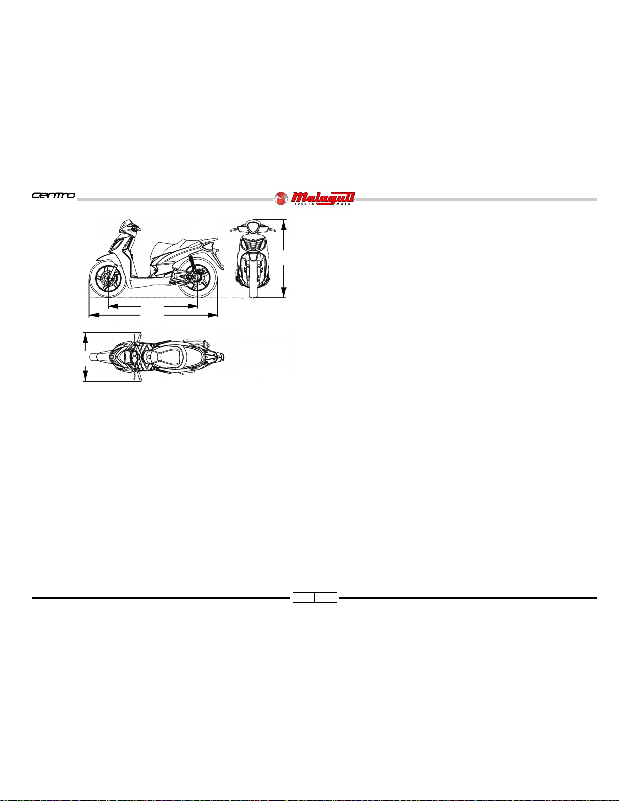
DIMENSIONS
Wheel base (A) m .......................................................................................1,340
Max. length (B) m........................................................................................ 2,000
Max. width (C) m .........................................................................................0,730
Max. height (D) m ......................................................................................1,150
Kerb weight kg ...............................................................................................115
Max. load with rider, passenger and luggage kg ..............................................165
CAPACITY
Engine oil cm3 ............................................................................................. 850*
Transmission oil cm3 ................................................................................... 150*
Fuel tank (total) l .................................................................................... 6* (1,7*)
ENGINE: 2 valve - 4 stroke single cylinder:
Type ......................................................................................... PIAGGIO C432M
n° Cylinders ...................................................................................................... 1
Bore x stroke mm ............................................................................. Ø 39 x 41,8
Capacity cm3 ............................................................................................... 49,9
Compression Ratio ...................................................................................11,7 : 1
Cooling .................................................................................................. forced air
Starting system ........................................................ electrical and/or kickstarter
lubrication system ................................................................................ wet sump
SPARK PLUG
Type ........................................................................... NGK CR8E - NGK CR8EB
TRANSMISSION
Primary drive: automatic transmission by V-belt speed change gear
Final: by gears.
Automatic centrifugal dry clutch.
FUEL SYSTEM
Carburettor KEIHIN CVK
Automatic starter
Fuel: unleaded petrol.
IGNITION
Electronic.
BRAKES
Front brake: disk type Ø 225 mm transmission and hydraulic calipers.
Rear brake: drum Ø 139 mm, mechanical transmission
CHASSIS
Made of steel pipes with a high resistance.
SUSPENSIONS
Front: hydraulically controlled fork Ø 28 mm - stroke 80 mm.
Rear: Swinging engine with hydraulic shock absorber featuring helical spring;
Stroke: 68 mm.
BATTERY
Type 12V, 9Ah, no maintenance.
TIRES
Front: 90/80 - 16 52P (tubeless)
Rear: 100/80 - 16 52P (tubeless)
* Indicative Value
F. 1
A
B
C
D
SPECIFICATIONS
Page 9

8 07/08
50 cc - 4 T
IDENTIFICATION DATA: FRAME N° / ENGINE N°
• The vehicle’s identification number (VIN) (A) is located on the rear side of the chas-
sis, under the helmet compartment.
• Engine identification data are located on the left-hand engine crankcase (B).
Any alteration to the vehicle identification data is pursued by the Law.
F. 3
• When ordering spare parts, also quote the vehicle identification data.
ANTI-TAMPERING PLATE
• An anti-tampering plate, bearing all vehicle identification data required by Directive
97/24/CE, is fitted inside the helmet compartment. If you have the helmet compartment
replaced, make sure the plate is fitted too.
This label must be neither removed nor changed.
F. 4
F. 2
A
B
Page 10

9 07/08
50 cc - 4 T
TYRES
Type: Tubeless (wiithout inner tube)
It is possible to use tyres with load and speed indexes that are higher than
or identical to those indicated.
It is however necessary for speed indexes to be identical for both tyres.
USE ONLY TYRES WITH THE RELEVANT TYPE APPROVAL.
The pressure of tires must be adjusted while the tire is at ambient
temperature.
Pressure differing from that indicated can lead to higher fuel
consumption, irregular wear of the tire, impaired vehicle performance
and riding conditions.
F. 5
Check the tire conditions (before every journey): if they are broken (cracked) or cut,
have them replaced as soon as possible.
• “T.W.I.” marks are provided all around the tire side walls. These correspond to tire
wear indicators, which are situated in the tire’s tread; if there is no difference between
the thickness of these indicators and the tread depth itself, the tire must be replaced.
Minimum tread depth (front and rear) is 2 mm (F. 6).
F. 6
PRESSURE
2.0 2.0 2.1
(29.0) (29.0) (30.5)
2.2 2.3 2.3
(31.9) (33.4) (33.4)
Page 11

10 07/08
50 cc - 4 T
NOTE - Maintenance operations should be performed more frequently if the vehicle is used in rainy weather, in dusty places or on rough
terrain.
Due to their simplicity, checks with no asterisk CAN also be carried out by technicians not authorised by MALAGUTI, but under
their direct responsibility.
Nr. : coupon
: check
: clean
: adjust
: replace
MAINTENANCE TABLE
Page 12
11 07/08
50 cc - 4 T
LUBRICANT TABLE
NOTE - Use only recommended products.
LUBRICANTS
ENGINE OIL (4 STROKE) FORMULA EXCEL SAE 5W40
ENGINE TRANSMISSION OIL T35 - 80W
AIR FILTER LUBRICANT AIR FILTER OIL
RADIATOR FLUID TOP FLUID
BRAKE CIRCUIT FLUID BRAKE FLUID DOT 4
FORK ROD OIL FORK OIL
Page 13
12 07/08
50 cc - 4 T
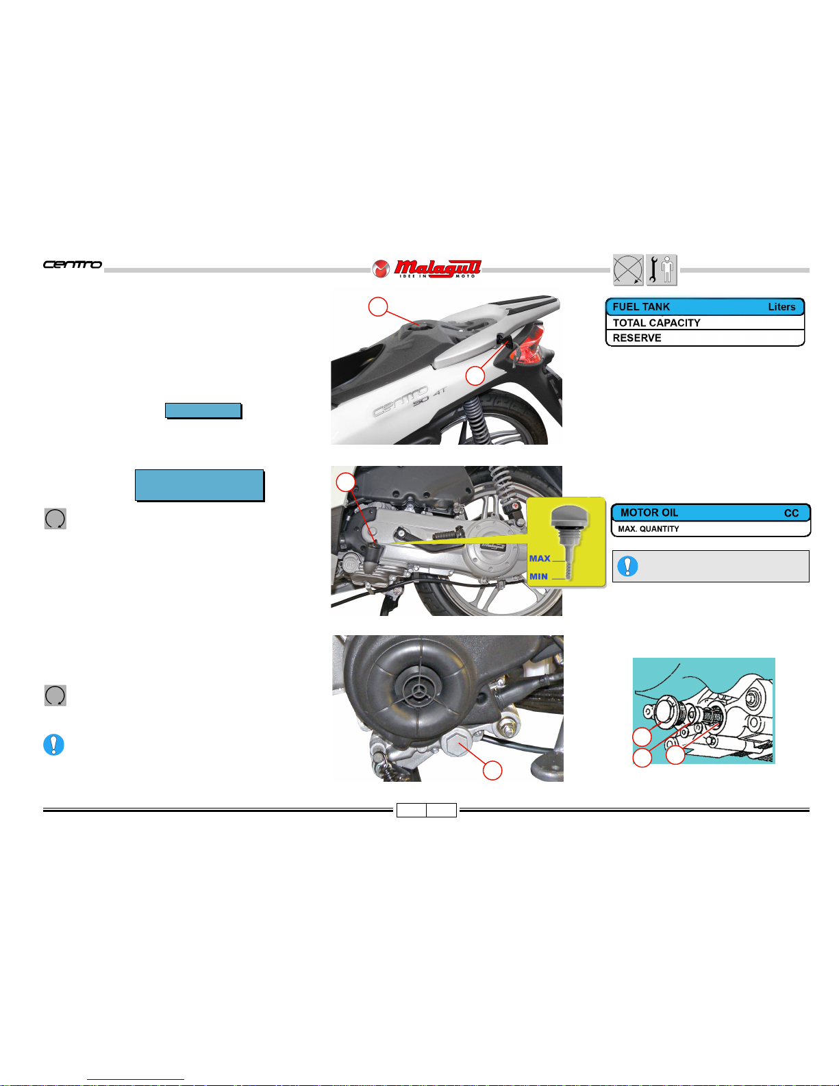
FUEL TANK
• The fuel tank cap (A) is accessible by raising the seat, using
the ignition key (B) and turning it clockwise.
Use unleaded gas.
F. 7
F. 8
• Place an appropriate drain pan under the engine (with the
vehicle on flat ground).
• Pull out the cap/ dipstick (A).
• Unscrew the drain plug (S) and let all the used oil drain out.
• Remove the drain plug (F) and the mesh filter (C).
• Wash the filter (C) with solvent.
• Check the wear conditions of the O-Ring (3) and replace if
necessary.
• Reassembly: O-Ring (B) e the filter (C).
• Screw on and tighten the drain plug (F).
• Top up the engine of oil specified and replace the cap/
dipstick (A).
Start the engine; leave it running for a few minutes,
and check that there are no leaks.
• Turn the engine off and check the oil level.
Dispose of used oil in accordance with current laws
in force.
CHANGE
Warm up the engine for a few minutes and then shut it
off.
• After the first 1,000 Km
• Every 6,000 KM
A
F
B
C
B
A
F. 9/a
Top with the oil
Q8 FORMULA EXCEL SAE 5W 40
F. 9
F
every 3.000 km
CHECK LEVEL
• The engine must be cold and the vehicle on level ground.
• The level is shown on the cap/ dipstick (A), in order to
check level, screw the cap back.
ENGINE OIL
850
6,0
1,7
Page 14
13 07/08
50 cc - 4 T
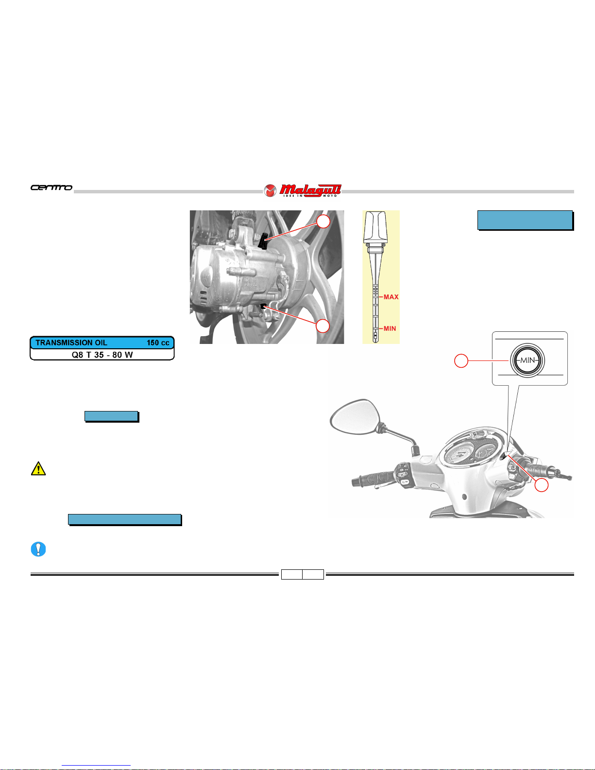
CHECK LEVEL/ TOP UP
• Cold engine
• Vehicle on level ground.
• Place a drip pan under the engine.
• Unscrew the oil dipstick (A), dry it and put it
back.
• Then extract again the dipstick, and check
that the oil level reaches the mark half way
between the “MIN.” and “MAX” marks.
• If necessary, top up with oil specified.
• Screw the oil dipstick (A) back.
TRANSMISSION OIL
CHANGE
If there is any debris or water in the brake fluid, it is essential that it be completely changed and the brake system must be bled. Excessive elasticity in the
brake lever is usually an indication that air is in the system.
CHANGE
• After the first 1,000 Km
• Every 12,000 Km
• Cold engine
• Vehicle on level ground
• Place a drip pan under the engine.
• Unscrew the oil dipstick (A).
• Unscrew the drain screw (B)
• Drain out all the used oil.
• Clean the threads of the drain screw and screw
back on.
• Refill the crankcase with oil specified.
• Screw the oil dipstick (A) back.
CHECK
• Visually check by way of the warning signal (S) located on the front brake reservoir,
with the vehicle on level ground and perfectly straight.
• The fluid level must be 3mm from the lower limit of the warning signal.
FRONT BRAKE FLUID
Do not mix different oil types when topping off.
every 30 days
Every 12,000 Km or 24 months
F. 1 1
S
F. 1 0
B
A
A
Page 15

14 07/08
50 cc - 4 T
BLEED BRAKE SYSTEM
FRONT CALIPER
NOTE - Position the vehicle in a stabile manner and
perfectly on level ground.
• Remove the oil pump reservoir cover (A),
unscrewing the relative screws (V2), in order to be
able to top off the fluid.
• Fill the brake fluid reservoir (B) to the highest level.
• Remove the rubber hood (C) of the bleeder screw
(V) and insert a rubber tube to recover the brake
fluid.
• Pump the right brake lever (D), prime it and bring
the system in pressure.
• Keeping the brake lever pumped, loosen the bleeder
screws (V), to allow air to escape. Then, tighten
the bleeder screw (V)
F. 12 F. 13
V
12 ± 16%
CHECK FRONT BRAKE
PADS AND DISK
• Check the condition of front brake
pads and disc every 2,000 Km.
• Carry out a visual check on the
thickness of the brake pads.
The minimum thickness of the brake
pad friction material must not be less
than 2mm.
• Replace the pads if they are close to the allowed limit, or if they are damaged.
F. 1 4
REPLACING PADS
C
V
B
D
V2A
F. 1 5
NOTE - The procedures for replacing front brake pads can be deduced
from the illustration shown below.
Page 16

15 07/08
50 cc - 4 T
CHECKING THE REAR BRAKE
• Make sure that the idle stroke of the lever is ~ 10 mm.
• Ad just the lever by means of the adjuster (A), if necessary.
F. 1 7
F. 1 6
FORK
CHECK OIL LEVEL IN THE
FORK LEG
• Remove the fork leg.
If a "limit switch" of the fork
is found, or if they produce
abnormal sounds, the oil level
inside the pins must be
checked. Removal of the legs
can be seen in F. 18.
• Insert a ruler or gauge and
check that the oil is at least
75 mm from the upper edge
of the leg.
• If necessary, top up with oil:
FORK OIL
CHANGE FORK OIL
• Place an appropriate drip pan under the slider and remove the screws (V).
• Drain out as much oil as possible.
• Proceed to dismantle the fork legs, as previously described.
• Turn the fork legs upside-down, to let the remaining oil drain out.
Hydraulic oil is corrosive and may cause personal injury.
Do not improperly dispose of used oil in the environment.
• Remount the drain screw (V).
NOTE - When remounting, replace the copper washer located under the screw (V).
• Check the oil level, as previously described.
• Reassemble the fork components and the fork on the motorcycle.
• Carefully pour the "new" oil in the fork.
V
17 ± 15%
Quantity per fork 90 cc.
F. 1 8
V
A
Page 17

16 07/08
50 cc - 4 T
DIGITAL CLOCK
• Reading date and month: press top button once (time will appear automatically after a few seconds).
• Reading seconds: press top button twice; to resume the initial configuration, press the button again.
• Setting month: press the bottom button twice and select the correct number with the top button.
• Setting date: press the bottom button 3 times and select the correct number with the top button.
• Setting time: press the bottom button 4 times and select the correct number with the top button.
• Setting minutes: press the bottom button 5 times and select the correct number with the top button.
Press the bottom button again to return to time display mode. If you have changed your settings, save them by pressing the top button.
INSTRUMENT BOARD
1) Analogue instruments, Speedometer
Current speed in kmh or mph.
2) Odometer
Total distance travelled in kmh.
3) Green turn indicator light
4) Blue high beam indicator light
5) Fuel level indicator
Orange zone: approaching reserve.
Red zone: reserve - Refuel!!
6) Battery level indicator
This indicates the charge level of the battery and correct operation
of the recharging system.
7) Digital clock
F. 1 9
7
6
5
4
3
2
1
To prevent damage, avoid washing instruments with pressurised system.
Page 18

17 07/08
50 cc - 4 T
KEY SWITCH
Ignition inhibited (extractable key)
Preset starting position (non extractable key)
Steering lock insert (Ignition inhibited: extractable key).
In case both of the equipped keys are lost the entire locking kit
must be replaced.
STARTING THE ENGINE
Before pushing the starter button to start the motor, first pull the front or rear brake lever and keep
it pulled.
Do not start the engine in a closed ambient, because the exhaust is highly toxic.
To not damage the injection system, never operate the "START" button if the fuel tank is
empty, or turn the key switch to "ON".
If the engine does not start, release the starter switch, wait a moment, and then press it
again. In order not to drain the battery, do not operate the starter for more than 10 seconds
on each try. Do not rev the engine to its limit when it is cold.
Start the engine with the headlights off.
HANDLEBAR CONTROLS
A
B
3 2 1
5
3
1
2
4
RIGHT HAND CONTROL
1) Counterweight
2) Throttle grip
3) Front brake lever
A) Light switch:
right = OFF
centre = parking and instrument board lights
left = low/high beam lights
B) Electric starter button.
LEFT HAND CONTROL
1) Rear brake lever
2) Counterweight
3) Horn button
4) Turn indicator switch
5) Button for turning off indicator lights
6) Light switch:
high beam
low beam
6
F. 2 0 F. 2 1
Page 19

18 07/08
50 cc - 4 T
LIGHTS
HEADLIGHT
The headlights are quartz lamps (halogen).
• High/Low beam lights (A). Halogen Bulb 12V - 60/55W (H4).
• Tail lights (B). Bulb 12V - 5W (W5W).
Change light bulb
• To reach the headlight bulbs it is necessary to remove the
front handle cover (see page 26).
LIGHT BEAM ADJUSTMENTS
• Place the vehicle in gear, 10 m from a wall.
• Turn on the low beam and keep the vehicle vertical without the kickstand and without people sitting on it.
• With a Philips screwdriver, adjust the headlight adjustment screws (R), keeping in mind that turning clockwise lowers the light beam and vice versa.
• Adjust the beam so that the lower line of the beam is about 95 cm off the ground when projected on a wall.
F. 2 4
C
C
TURN SIGNALS FRONT
• Bulb (C) 12V - 10W (RY 10W).
Light bulb replacement
• To reach the front direction indicators bulbs it is necessary to
remove the front cover and the battery cover (see see page 22).
F. 2 3
R
F. 2 2
B
A
Page 20

19 07/08
50 cc - 4 T
REAR LIGHT UNIT
• Tail lights (P)
Light bulb 12V - 5W (W5W).
• Brake lights (S)
Light bulb 12V - 10W (R10W).
• Turn signals (E) 12V-10W
• Undo the two central
screws securing the
parabolic spring.
F. 2 8
Light bulb replacement
• Unscrew the screws (V2).
F. 2 6
V2
V2
• To access the bulbs,
remove the frame (A) and
the pane of glass (B).
F. 2 7
A B
F. 2 5
E
E
S
S
PP
Page 21

20 07/08
50 cc - 4 T
NUMBER PLATE LIGHT
Light bulb 12V - 5W (W5W)
To check that a light bulb (C ) is properly
functioning, position the light switch,
which is located on the right control panel,
in the center position and turn the key to
the starting position.
Light bulb replacement
• Remove the number plate light (F),
unscrew the screws (V).
• Remove the rubber lamp holder from the
plastic cover.
• Replace the light bulb.
• Reposition the lamp holder and remount
the cover.
When performing the operations
described above, be very careful
not to damage the near by parts
(transmission, cables, gaskets,
etc.).
F. 3 1
F
V
F. 3 0
C
Tail light
• Take out the lamp holder from inside the headlight.
• Replace the light bulb.
• Reposition the rubber lamp holder (pressure) and remount the cover.
Stop light and turn signal light
• Remove the coloured hood that is held by two hooks.
• Replace the light bulb.
• Reposition the coloured hood and remount the cover.
When performing the operations described above, be very careful to not
damage the near by parts (transmission, cables, gaskets, etc.).
• Disconnect the connector
(C).
• Remove the parabolic spring
carefully.
F. 2 9
C
Page 22

21 07/08
50 cc - 4 T
FUSES
The electric wiring includes three fuses that are located in the front case and protect
the main components from any malfunctions.
FUSE REPLACEMENT
Open the case and take out the fuse and replace it with one having equal capacity.
Spare fuses are located inside the compartment (S).
Do not replace fuses with others that have a higher capacity, as it could
seriously damage the electrical system and cause the vehicle to catch fire
if there is a short circuit.
It is important to identify the cause of blown fuses.
NOTE - Use the appropriate grippers (P) when replacing a fuse.
F. 3 2
P
S
S
A
B
C
Page 23

22 07/08
50 cc - 4 T
BATTERY (12V - 9Ah)
The battery compartment is located in the front section of
the vehicle.
FITTING BATTERY (pre-delivery operation)
To fit battery, proceed as follows:
• Take a charged battery.
• Remove the 10A general protection fuse.
• Loosen (V4) and remove the front guard (A).
• Loosen the four screws (V) and remove the cover of battery
case (B).
• Insert the battery (C) and make sure it is correctly seated.
• Connect the battery wiring:
- positive pole (+) RED + RED/BLUE cables
- negative pole (-) to the BLACK cables.
• Wrench down the battery terminals.
• Refit the 10A general protection fuse previously removed.
• Check that the battery and the wiring harness are correctly
installed.
• Refit the cover of battery case and the front guard.
NEVER invert the cable connections.
Do not use the battery without the battery inserted and
connected to wires of the main harness. This could
cause breakdowns and short circuits in the electrical
system and components.
It is advisable to use gloves and protective eyewear,
when the battery must be removed from its housing; for
example, when it needs to be recharged.
F. 33 F. 34
F. 35 F. 36
C
A
V4
V
B
C
Page 24

23 07/08
50 cc - 4 T
Danger of explosion! Do not use open flames (lighters, matchsticks, etc.).
The battery contains highly toxic sulphuric acid. Avoid contact with the eyes, skin, and clothes. Keep the battery
out of reach from children.
If for charging/ maintenance of the battery the special electrical outlet connection is used, open the battery
case to permit proper ventilation.
CHARGE BATTERY
• To carry out this operation, it is advisable to remove the
battery from its housing, unless the special electrical outlet
(A) is used.
• Disconnect cables.
• It is a good rule to recharge using amperage that is equal to
1/10 of the power of the battery charger.
• Remount the battery, paying attention to connect the positive
cable (red/blue) to the + pole and the negative cable to the
- pole.
• Properly tighten the battery clamps.
• It is important that the battery always remains fully charged;
therefore, during the winter months or when the vehicle
remains unused, it should be recharged at least once a
month.
F. 3 8F. 3 7
A
F. 3 9
Page 25

24 07/08
50 cc - 4 T
Spark plugs with a thermal grade that is different than that deduced by the advised symbols may seriously
damage the engine.
Replace all spark plug with cracks on the insulator or corroded electrodes.
SPARK PLUG
REPLACEMENT
Remove the spark plug when the engine is cold.
Type of spark plug to be used: NGK CR8E - NGK CR8EB
• For maintenance, disassemble the central panel under the seat (P), remove the three fastening screws (V) and lift the
internal profile (with the help of a screwdriver) that is held on two lugs in the foot rest board, carefully extract the hood
(C ), with small clockwise and anti clockwise movements; then unscrew the spark plug.
• Examine the condition of the sparkplug. Deposits and colorations of the insulator provide useful information on the
thermal grade, on the carburetion, on the lubrication and on the general condition of the engine. If there is a light
brownish color on the insulator around the central electrodes, it means that it functions properly.
• After removing the sparkplug, proceed to clean thoroughly the electrodes and insulators, using a metallic brush. Adjust
the electrode gap, using a laminar feeler gauge: the gap must be 0,5 ÷ 0,6 mm.
• Remove any residue, using jets of compressed air.
• Grease the sparkplug threads with motor oil and manually rescrew it.
• Tightening the spark plugs:
17,5
every 6,000 km
F. 4 0
F. 4 1
P
C
V
Page 26

25 07/08
50 cc - 4 T
PROCEDURES FOR DISMANTLING AND
REMOVING COMPONENTS
REASSEMBLY NOTE
• Remove the upper cover, sliding
it towards the rear part.
F. 4 2
F. 4 4
F. 4 3
D
V2
REAR VIEW
MIRROR (Left)
• Uncover and loosen the nut (D).
• Unscrew the window holder arm, by
turning it anti-clockwise.
• Remove the protection (A).
UPPER
COVER
• V2.
F. 4 5
REAR VIEW
MIRROR (Right)
(optional)
• First remove the protection
cap (B).
B
A
Page 27

26 07/08
50 cc - 4 T
F. 4 6 F. 4 7
F. 4 8
F. 4 9
V4
V4
V
V
1 ± 10%
V4
1 ± 10%
FRONT HANDLEBAR COVER
•V.
• V4.
• Free and partially extract the
handlebar unit, carefully, as
to not damage the paint of
the under shield or rip the
electrical headlight wires.
• To clear the front handlebar
cover, push the area
indicated in the figure (on
both sides), paying
attention to not damage the
hooking points.
Page 28

27 07/08
50 cc - 4 T
A
B
F. 5 1F. 5 0
FRONT
COVER
• V4.
•W.
F. 5 2 F. 5 3
V4
1 ± 10%
W
1 ± 10%
W
V4
• Disconnect the
lamp holder (A)
• Extract the taillights lamp
holder (B).
• Remove the front handlebar
cover.
Page 29

28 07/08
50 cc - 4 T
F. 5 4
F. 5 5
ACCESS
(after removing the front cover)
A) Antitheft preset connector
B) Key switch connector
C) Battery case cover (pag. 22)
D2
3 ± 20%
SEAT
• D2.
D2
A
C
B
F. 5 7
F. 5 6
V4
V
A
V
V
4
5 ± 20%
•V.
• V4.
HELMET
COMPARTMENT
• Remove the fuel tank plug
and fit an adequate
protection onto the filler (A)
in order to prevent any
outside particle to get into
the tank.
Page 30

29 07/08
50 cc - 4 T
F. 5 8
F. 5 9
F. 6 0
D2
3 ± 20%
• Partially lift the helmet
compartment, as it is
constrained by the seat
locking device cable.
• Remove the locking/opening unit, complete with
the transmission cable.
D2
SEAT BLOCKING DEVICE
• D2.
Page 31

30 07/08
50 cc - 4 T
ACCESS
(after removing the helmet compartment)
A - Fuel tank
B - Fuel level gauge
C - Fuel gauge connector
1) Throttle cable
2) Electric starter, carburator
3) Carburator valve cover
4) Vacuum pipe and fuel valve.
5) Oil fumes expansion pipe
B
C
A
1 2 3 4 5
F. 6 1
F. 6 2
Page 32

31 07/08
50 cc - 4 T
• During operations, screw the tank cap on the union (A),
to avoid that any foreign matter falls inside.
• Remove the adhesive tape (B), release the sheaths
(F) and disconnect the inside connector.
• V4.
• Remove the fuel level sensor (G).
F. 6 3
F. 6 5
FUEL LEVEL SENSOR
Do not smoke or
use open flames,
while operating on the fuel
tank.
• During the operation, screw
the tank cap, to avoid that
any foreign matter falls
inside.
• V4.
FUEL TANK
V4
A
B
G
V4
V4
5 ± 10%
Remove the tank and place it far from heat sources and sparks and/
or open flames.
F. 66/a
V4
• Remove the cover (1).
• Undo the clamp (B) and remove the vacuum valve (C).
B
C
F
F. 6 6
1
NOTE - When reassembling, insert the floater (C) so
that the base remains as it was originally. It is
advisable to mark the correct position before
removal. Check the condition of the gaskets
(D) and replace them if necessary.
F. 6 4
V4 G
C
D
Page 33

32 07/08
50 cc - 4 T
•V3
• Lift carefully the lower part
(using a screwdriver), that is
secured to the footbar by
means of two coupling teeth.
CENTRAL
BAR
2) Voltage regulator
3) CDI unit
4) Start relay
ACCESS
• Spark plugs pipette (1).
F. 6 7
1
V3
F. 6 9
2
3
4
F. 6 8
• Ground end fixing screws
can be reached (M - F. 68),
through the hole (F).
F. 7 0
F
Page 34

33 07/08
50 cc - 4 T
•W.
SIDE STRUTS
• V3.
• V2.
• Remove the side pins and
the front coupling element
(A).
PASSANGER
LEVERS
• Undo the upper screw (V),
holding the self-locking nut
underneath.
F. 7 1
F. 7 2
F. 7 3 F. 7 4
V3
V2
W
V
A
Page 35

34 07/08
50 cc - 4 T
• Release the footbar from the
rear fairing with care, paying
attention not to lose the four
fasteners (A).
Clean and grease the
fulcrum pin (P).
• Unscrew the screws (V),
remove the pillion staff and
recuperate the underlying
spring (M).
D
V
F. 7 5
P
G
M
FOOTBAR
• V4.
• W4.
V4
5 ± 10%
F. 7 7
F. 7 6
A
A
A
V4
W4
Page 36

35 07/08
50 cc - 4 T
V
V
2
43 ± 15%
Do not forget to fit
the bushings (B)
opposite of the
screws (V2).
REAR FAIRING
REAR HANDLE
• V - After removing the
closing cap.
• V2.
A
F. 7 8 F. 7 9
F. 8 1F. 8 0
V
V2
A
V2
B
B
C
V2 V2
V
• Remove the rear handle
including the opening/
locking seat device (A).
REAR LIGHT UNIT
• V2.
• Rear light frame assembly
(B).
• Rear light glass assembly
(C).
• Number plate light support (A).
NUMBER PLATE LIGHT
SUPPORT
•V.
Page 37

36 07/08
50 cc - 4 T
• V2A.
V2A
F. 8 3
F. 8 2
V4
5 ± 10%
F. 8 4
V4
V4
• Carefully take out the rear
light unit.
• Disconnect the wires.
FULL REAR FAIRING
• V4.
Page 38

37 07/08
50 cc - 4 T
•V.
V
5 ± 10%
• Remove the rear fairing
with care.
• Put the fairing in a safe
place, away from
accidental crashes and
heat sources.
ACCESS
RIGHT SIDE
1) Electric starter
resistance connector.
LEFT SIDE
2) Fuel sensor connector
(inside the sheaths).
F. 8 6
F. 8 5
F. 8 8
F. 8 7
V
2
1
Page 39

38 07/08
50 cc - 4 T
• V3.
F. 8 9
F. 9 0
V3
V3
A
• Pay attention not
to damage to the
coupling system
(A).
FRONT PART REAR PART
• V3.
REAR FAIRING BREAKDOWN
V3
Page 40

39 07/08
50 cc - 4 T
V2
5 ± 10%
•W2.
•V.
V
5 ± 10%
V4
2 ± 10%
F. 9 1
V2
F. 9 2
F. 9 3
F. 9 4
A
V
C
B
W2
•V.
V4
V
V4
LEGSHIELD
• V2.
• Bag holder hook (A).
• Open (carefully) the leg
shield, on the left side.
• Remove the fuse holder box.
• Disconnect the connector (C)
of the charge plug.
• Extract the cover (B) of the
key switch.
•V4
Page 41

40 07/08
50 cc - 4 T
• Remove the leg-fender.
NOTE - After removing the leg-fender,
pay attention not to lose the
fasteners (A).
ACCESS
(after the legshield is removed)
1) Front turn signals
2) Key switch
3) Horn
4) Handlebar fixing nuts
5) Steering wheel regulator ferrules
6) Fuse box
F. 9 5
F. 9 7
F. 9 6
3
A
4
5
6
1 2
1
Page 42

41 07/08
50 cc - 4 T
F. 9 8
V2
V
A
F. 9 9
F. 100
F. 101
V
A
V2
10 ± 15%
V
7 ± 10%
V1
B
KEY SWITCH
• Disconnect the connector from the wiring.
• Unscrew the tamperproof screws (V2).
HORN
• Disconnect the "faston" (A).
•V -
FRONT
MUDGUARD
•V
• Clamp (A)
•V1
• Clamp (B)
Page 43

42 07/08
50 cc - 4 T
FRONT WHEEL
• Unscrew the nut (D), holding the wheel pin with a wrench.
FRONT BRAKE DISC
• When removing the front
wheel, check the condition of
the brake disc. In case of
deep scoring or if the thickness is below the minimum
limit of 3.5 mm, remove it
by unscrewing the screws
(V5) and replace it.
V5
11 ± 10%
•V.
• Spacer (A).
• V3.
• Remove the wheel pin (P).
• Take off the wheel.
• Pay attention not to lose the
spacer (A).
Do not use the brake
lever, with the wheel
removed.
• Remove the front mudguard.
F. 102
F. 1 03
F. 104
F. 105
P
A
DV5
V3
3 ± 10%
Apply Loctite threadlocker (Strong type) on the screw threading.
V3
A V
Page 44

43 07/08
50 cc - 4 T
• Spacer (A)
• Odometer transmission (B)
• Washer (R )
• Wheel pin (P)
• Spacer (C)
• Shim (A1)
• Wheel pin (D)
A
20 ± 20%
V2
30 ± 20%
D
53 ± 10%
F. 106
A
A
F. 107
V2
G
V2
C
D
B
A
P
R
A1
SEQUENCE OF FRONT WHEEL REASSEMBLY
FRONT BRAKE CALIPER
• Place an appropriate drain pan under the brake calliper.
• Unscrew the hydraulic fitting (A).
Empty the hydraulic circuit completely, pouring the fluid in a special container for
proper disposal in accordance with specific waste disposal laws.
• V2.
• Remove the calliper.
Hydraulic oil is corrosive and may cause personal injury.
Remove the calliper, taking care that fluid line does not get damaged and
the disc and pads do not get dirty. At the end of removal and replacement
operations, check that there are no losses, dry up any traces of fluid and
bleed the system as indicated in page 14.
During reassembly, change the gaskets (G).
Page 45

44 07/08
50 cc - 4 T
F. 108
V2
V2
• Jumper (B)
• Complete front brake pump.
Brake fluid is corrosive.
• Twistgrip (C)
• Right switch (D)
• Left switch (F)
• Cut the clamps that fasten
cables and pipes.
• Unscrew the nut (G) and
extract the pin (H).
• Remove the handle.
HANDLEBAR
• Front handlebar.
• Rear handlebar (M).
• Disconnect the accelerator
transmission (A).
• Disconnect the dashboard
connectors.
• Disconnect the “Stop”
faston.
• Undo the odometer cable
ring nut.
• Remove (with care) the rear
handlebar cover including
the dashboard.
F. 1 09
A
G
50 ± 20%
M
FRONT SHIELD
• Release the leg-fender
(P. 39).
• Remove the front
mudguard (P. 41).
• Remove the front
wheel (P. 42).
• V2.
• Take out the shield
(with care)
5 ± 10%
V2
F. 111
C D
B
F
C
F. 110
G
H
Page 46

45 07/08
50 cc - 4 T
Top bearings (Ø 3/16") n° 22
Lower bearings (Ø 1/4") n° 19
B
12 ± 10%
A
140 ± 15%
V
30 ± 20%
V
A
B
F. 112
F. 113
B
A
F. 1 14
C
C
A
B
S
S
FORK LEG
• Loosen (V)
• Raise the fork leg a few
millimetres (A).
• Take out the elastic ring (B)
• Slide out the fork leg (A)
downwards.
FORK
NOTE - When removing the fork leg, as well
as the full fork, the following should
be removed beforehand:
- Front wheel (page 42)
- Front mudguard (page 41)
- Front brake calliper (page 43)
(left wheel stem)
For the full fork, also remove the:
- Front shield (page 44)
- Handlebar (page 44)
•To check the oil level and to change oil,
see page 15).
FULL FORK
• Upper ring nut (A)
• Lower ring nut (A)
NOTE - When extracting the fork unit, take care with the bearings (S) spilling out.
• Remove grease the seat of the caps (C). Check the usage conditions and if
necessary replace them.
Grease and remount the fork unit.
Page 47

46 07/08
50 cc - 4 T
F. 115
• Undo the two screws (W)
and remove the gasket (G).
• Remove the muffler.
W
8 ± 15%
F. 117
F. 1 18
D
B
R
V2
• Nut (D).
• Remove the rear wheel.
D
100 ± 20%
F. 1 16
G
V2
C
W
V2
30 ± 20%
MUFFLER
Before operating on
the muffler and the
exhaust pipe, ensure
that the components
are cool.
• V2.
REAR
WHEEL
• Remove beforehand the
muffler
• Undo the adjuster (R).
• Remove the split pin (C)
and the nut cover (B).
Page 48

47 07/08
50 cc - 4 T
INTAKE
SYSTEM
F. 119
F. 122
• Release the clamp (A) and remove the exhaust unit.
• Refer to the picture to reach the air filter (B).
F. 120
F. 121
V VS
V2
C
B
A
V1
V2
• V2.
REAR
MUDGUARD
Right side
•V.
• Vs.
Left side
• V1.
AIR FILTER MAINTENANCE
• Soak the filtering element in a special solvent solution for filters, for a few minutes.
• Squeeze the filter (wearing rubber gloves) until all traces of the solvent are eliminated.
• Apply oil for air filters on the entire surface of the filter, eliminating any extra oil; the result should be a uniformly impregnated filter without excess oil dripping off.
• If the filter element is damaged, replace it with a new original one.
When remounting the air filter unit, check that the seal (C) is correctly inserted in the relative housing.
Page 49

48 07/08
50 cc - 4 T
Support the central
part of the frame.
• Top nut (Ds)
• Lower screw (Vi)
• Remove the upper screw
(Vs).
• Extract the shock absorber.
REMOUNTING THE
SHOCK ABSORBER
• First fit the upper screw (Vs) with the
washers and the nut (Ds).
• Then the lower screw (Vi), with the
washers and the lower nut (Di).
Vs
40 ± 15%
Vi
40 ± 15%
SHOCK
ABSORBER
F. 123
F. 124
DS
Vi
DS
Vi
Di
Vs
ENGINE
• Remove beforehand:
- Rear fairing (page 35)
- Lower fixing screws, shock absorber
- Air filter unit (page 47) (not compulsory)
- Muffler (page 55)
It is essential that all the tube and cable ties are cut from the engine and all
relevant connectors are disconnected.
After remounting the previously removed components, all cables, pipelines and ties should result as they were originally; in concern to this, carefully consult the following pages.
Page 50

49 07/08
50 cc - 4 T
• Disconnect the flywheel
connector (A).
F. 125
F. 1 26
F. 1 28
• Release the hose (D) by undoing the clamp (E).
• Release the camping spring (F).
• Release the rear brake cable (G) from the cable ring supports (H).
• Disconnect the cables
(B - C) of the starter motor.
• Disconnect the oil fume
expansion pipe (I).
• Disconnect the vacuum
pipe (L).
• Release the accelerator
cable (M).
IL
M
CB
A
GE
HH
F. 127
D
F
Page 51

50 07/08
50 cc - 4 T
• Cut the clamp and remove
the connector protection
sheaths (A).
• Disconnect the electric
starter connector (A).
F. 129
F. 1 30
F. 131
F. 1 32
• Disconnect the rear brake
cable (B).
• Disconnect the spark plug
(C).
• Unscreew the nut (D).
Remember to fit the
washer.
C
45 ± 15%
D
A
D
B
Page 52

51 07/08
50 cc - 4 T
• Slide off the pin (P).
Remember to fit the
washer.
F. 133
P
F. 134
FRAME SIZE CHECK
• In case of suspected deformation (even slight) of the frame following an
accident, perform a size check of the frame.
Check that the distance A = 1132 mm ( ± 2mm tolerance)
• If it results to be outside of the tolerance, replace the frame.
It is absolutely forbidden to deform the frame to restore the
original distance (A).
Raise the rear part of the motorcycle before sliding off the engine pin. It is advisable to have a second operator available to help carry out this operation.
Removing the engine from the frame is a task that should be performed with care
and the utmost attention, in order to avoid crushing of the hands, lower limbs and
safeguard the integrity of the engine.
The removal of parts and components that allow the engine to be separated from
the frame includes a certain number of bands being cut. These must be replaced
and positioned as they were originally. For this purpose, consult the illustrations
on the following pages.
Page 53

52 07/08
50 cc - 4 T
F. 135
F. 136
F. 137 F. 138
CABLE POSITIONING, "PIPE SYSTEM" AND ANCHORING TIES.
Page 54

53 07/08
50 cc - 4 T
F. 139 F. 140
Page 55

54 07/08
50 cc - 4 T
F. 141
F. 142
Page 56

55 07/08
50 cc - 4 T
F. 143
Page 57

56 07/08
50 cc - 4 T
F. 144
F. 145
Page 58

57 07/08
50 cc - 4 T
F. 146
Page 59

58 07/08
50 cc - 4 T
F. 148
F. 147
Page 60

59 07/08
50 cc - 4 T
F. 149
F. 150
Page 61

60 07/08
50 cc - 4 T
F. 151
F. 152
Page 62

61 07/08
50 cc - 4 T
F. 153
 Loading...