


Makita MS26C, MS26U Manual
A
|
|
|
|
|
MS-26 U |
MS-26 C |
|
|
|
|
|
GB |
Brush Cutter |
String Trimmer |
|
|
|
|
|
F |
Débroussailleuse |
Taille-bordure |
|
|
|
|
|
D |
Motorsense |
Rasentrimmer |
|
|
|
|
|
I |
Decespugliatore |
Tagliabordi |
|
|
|
|
|
NL |
Bosmaaier |
Graskantmaaier |
|
|
|
|
|
E |
Desbrozadora |
Cortabordes |
|
|
|
|
|
P |
Roçadeira |
Máquina de cortar relva |
|
|
|
|
|
DK |
Buskrydder |
Trådtrimmer |
|
|
|
|
|
GR |
Θαμν κ πτικ |
λ κ πτικ |
|
|
|
|
|
|
|
|
Instruction manual |
|
|
|
Manuel d’instructions |
|
|
|
Betriebsanleitung |
|
|
|
Istruzioni per l’uso |
|
|
|
Gebruiksaanwijzing |
|
|
|
Manual de instrucciones |
|
|
|
Manual de instruηυes |
|
|
|
Brugsanvisning |
|
|
|
Οδηγίες χρήσης |
MS-26 U |
MS-26 C |
|
|

Important:
Read this instruction manual carefully before putting the Brush Cutter/String Trimmer and strictly observe the safety regulations! Store this instruction manual in a safe place for future reference.
Important:
Lire soigneusement ce manuel d’instructions avant d’utiliser la débroussailleuse/taille-bordure et observer strictement les consignes de sécurité ! Conserver ce manuel dans un endroit sûr pour toute référence future.
Wichtig:
Lesen Sie vor Verwendung der Motorsense bzw. des Rasentrimmers diese Bedienungsanleitung aufmerksam durch und halten Sie die Sicherheitsregeln strikt ein! Bewahren Sie diese Bedienungsanleitung zum späteren Nachschlagen an einem sicheren Ort auf.
Importante:
Leggere attentamente il presente manuale d'istruzioni prima di sistemare il decespugliatore/tagliabordi e osservare rigorosamente le norme di sicurezza! Conservare questo manuale d'istruzioni in un posto sicuro per riferimenti futuri.
Belangrijk:
Lees deze gebruiksaanwijzing aandachtig voordat u de bosmaaier/graskantmaaier gebruikt en leef strikt de veiligheidsvoorschriften na. Bewaar deze gebruiksaanwijzing op een veilige plaats zodat u deze later opnieuw kunt raadplegen.
Importante:
Lea este manual de instrucciones con atención antes de utilizar la desbrozadora / cortabordes y cumpla estrictamente la normativa de seguridad. Guarde este manual de instrucciones en un lugar seguro para futuras consultas.
Importante:
Leia cuidadosamente este manual de instruções antes de utilizar a Roçadeira/Máquina de cortar relva e cumpra todas as normas de segurança! Guarde este manual de instruções num local seguro para consultas futuras.
Vigtigt:
Læs denne brugsanvisning omhyggeligt igennem inden brug af buskrydderen/trådtrimmeren og overhold sikkerhedsbestemmelserne til punkt og prikke. Opbevar denne brugsanvisning på et sikkert sted, så du har den til fremtidig brug.
Σημαντικ :
Διαβάστε αυτό το εγχειρίδιο οδηγιών πριν τοποθετήσετε το Θαμνοκοπτικό/Χλοοκοπτικό και τηρήστε με ακρίβεια τους κανονισμούς ασφαλείας! Φυλάξτε αυτό το εγχειρίδιο σε ένα ασφαλές μέρος για μελλοντική αναφορά.
2

Thank you for purchasing this DOLMAR Brush Cutter/String Trimmer. DOLMAR Brush Cutters/String Trimmers are developed as a product of our many years of knowledge, experience, and a detailed development programme.
Please read this booklet thoroughly to ensure you gain the best possible performance and outstanding results that your DOLMAR Brush Cutter/String Trimmer can provide.
English |
|
Table of Contents |
Page |
Symbols ........................................................................ |
3 |
Safety instructions......................................................... |
4 |
Technical data MS-26 U, MS-26 C ............................... |
8 |
Names of parts.............................................................. |
9 |
Mounting the handle ................................................... |
10 |
Mounting the protector ................................................ |
11 |
Mounting the cutter blade/nylon cutting head ............. |
12 |
Fuel/Refuelling ............................................................ |
13 |
Correct handling.......................................................... |
14 |
Important operating points/stopping |
|
the cutter/trimmer........................................................ |
14 |
Resharpening the cutting tool ..................................... |
16 |
Servicing instructions .................................................. |
17 |
Storage ....................................................................... |
19 |
Symbols
You need to note the following symbols when reading the instructions manual.
Read instruction Manual
Take Particular care and Attention
Forbidden
Keep your distance
Flying object hazard
No Smoking
No open flames
Protective gloves must be worn
Kickback
Keep the area of operation clear of all persons and animals
Wear sturdy boots with nonslip soles. Steeltoed safety boots are recommended.
Wear eye and ear protection (for String Trimmer only)
Wear protective helmet, eye and ear protection (for Brush Cutter only)
Do not use metal blades (for String Trimmer only)
Maximum permissible tool speed
Hot surfaces - Burns to fingers or hands
Fuel and oil mixture
Engine-Manual start
Emergency stop
First Aid
Recycling
ON/START
OFF/STOP
3

Safety instructions
General Instructions
–To ensure correct operation, make sure that you read and fully understand this instruction manual to familiarise yourself with how to use the Brush Cutter/ String Trimmer. Using this equipment without understanding how to operate it correctly may result in serious injury to yourself or others.
–Only lend the Brush Cutter/String Trimmer to people who have proved experienced with Brush Cutter/String Trimmers. Always lend them this instruction manual at the same time.
–If this is your first time using an engine powered cutter, consult your dealer for basic instructions.
–Children and young persons aged under 18 years must not be allowed to operate the Brush Cutter/String Trimmer. Persons over the age of 16 years may use the device for training purposes, only whilst under supervision of a qualified trainer.
–Use Brush Cutter/String Trimmers with the utmost care and attention.
–Only operate the Brush Cutter/String Trimmer if you are in good physical condition. Perform all work calmly and carefully. Users must accept responsibility for those around them.
–Never use the Brush Cutter/String Trimmer after consumption of alcohol or medicines, or if you are feeling tired or ill.
Intended use of the equipment
–The Brush Cutter/String Trimmer is only intended for cutting grass, weeds, bush and other such undergrowth, and should not be used for any other purpose such as edging or hedge cutting as this may cause injury.
Personal protective equipment
–Always wear clothing that is both functional and appropriate to your work, i.e. tight-fitting, but not so tight as to cause uncomfortable movement. Do not wear either jewelry or clothing which could become entangled with bushes or shrubs.
–In order to avoid head, eye, hand, or foot injuries, as well as to protect your hearing during operation, the following protective equipment and protective clothing must be used while using the Brush Cutter/String Trimmer.
–Always wear a helmet where there is a risk of falling objects. The protective helmet (1) is to be checked at regular intervals for damage and is to be replaced at the latest after 5 years. Use only approved protective helmets.
–The visor (2) of the helmet (or alternatively goggles) protects the face from flying debris and stones. During operation of the Brush Cutter/String Trimmer, always wear goggles or a visor to prevent eye injuries.
–Wear adequate noise protection equipment to avoid hearing impairment (ear muffs (3), ear plugs etc.).
–Work overalls (4) protect against flying stones and debris. We strongly recommend that you wear work overalls.
–Special gloves (5) made of thick leather are part of the prescribed equipment and must always be worn during operation of the Brush Cutter/String Trimmer.
–When using the Brush Cutter/String Trimmer, always wear sturdy shoes (6) with a non-slip sole. Such shoes protect against injuries and ensure good footing.
Starting the brush cutter
–Make sure that there are no children or other people within a working range of 15 meters (50ft), also pay attention to any animals in the working vicinity.
–Before use, always check that the Brush Cutter/String trimmer is safe for operation:
Check that the cutting tool is secure, that the control lever can be operated easily, and that the control lever lock is functioning correctly.
–Rotation of the cutting tool during idling is prohibited. Check with your dealer if you think the equipment may need adjusting. Check to make sure that the handles are clean and dry, and that the start/stop switch is functioning correctly.
(1)
(2)
(3)
(4)
(5) (6)
Diagram
15 meters
4

–Start the Brush Cutter/String Trimmer only in accordance with the instructions. Do not use any other methods to start the engine!
–Only use the Brush Cutter/String Trimmer and tools for the specified purposes.
–Only start the Brush Cutter/String Trimmer engine after the equipment is fully assembled. Do not operate the equipment until all of the appropriate accessories are attached!
–Before starting, make sure that the cutting tool is not in contact with hard objects such as branches, stones etc. as the cutting tool will rotate when starting.
–Switch off the engine immediately if any type of engine problem occurs.
–Should the cutting tool hit stones or other hard objects, immediately switch off the engine and inspect the cutting tool.
–Inspect the cutting tool at short regular intervals for damage (inspect for hairline cracks using the tapping test).
–Only operate the Brush Cutter/String Trimmer after attaching and adjusting the shoulder strap to the correct length. The shoulder strap must be adjusted to the user's size and fastened to prevent fatigue during operation of the equipment. Never hold the cutter with one hand during operation.
–During operation, always hold the Brush Cutter/String Trimmer with both hands.
Always ensure you are on safe footing.
–Operate the Brush Cutter/String Trimmer in such a manner as to avoid inhalation of the exhaust gases. Never run the engine in an enclosed space such as inside a room (risk of gas poisoning). Carbon monoxide is an odorless gas.
–Always switch off the engine when resting, or if you intend to leave the Brush Cutter/String Trimmer unattended, and place it in a safe location to prevent injury to other people and damage to the equipment.
–Never put the hot Brush Cutter/String Trimmer onto dry grass or onto any other combustible materials.
–The cutting tool must always be equipped with the appropriate guard. Never run the cutter without this guard!
–All protective installations and guards supplied with the equipment must be used during operation.
–Never operate the engine if the exhaust muffler is faulty.
–Shut off the engine during transport.
–During transport over long distances, always use the tool protection equipment included.
–Ensure the Brush Cutter/String Trimmer is positioned safely during transport to avoid fuel leakage.
–When transporting the Brush Cutter/String Trimmer, ensure the fuel tank is completely empty.
–When unloading the Brush Cutter/String Trimmer from a truck or other such vehicle, never drop the engine to the ground, as doing so may severely damage the fuel tank.
–Unless in an emergency, never drop or cast the Brush Cutter/String Trimmer to the ground as doing so may severely damage the Brush Cutter/String Trimmer.
–Always lift the entire equipment from the ground when moving it. Dragging the equipment on its fuel tank is extremely dangerous and may cause fuel to leak, which may cause fire.
Refuelling
–Shut off the engine during refuelling, keep away from open flames and do not smoke during refuelling.
–Ensure mineral oil products do not come into contact with skin. Do not inhale the fuel vapor. Always wear protective gloves during refuelling. Change and clean protective clothing at regular intervals.
–To prevent soil contamination (environmental protection), make sure you do not spill fuel or oil on the ground. If you do spill fuel, clean the Brush Cutter/ String Trimmer immediately.
–Make sure fuel does not come into contact with your clothing. If fuel does come into contact with your clothing, change your clothing immediately to prevent fire.
–Inspect the fuel cap at regular intervals to make sure that it can be securely fastened and does not leak.
–Carefully tighten the fuel tank cap. Once refuelling is complete, move to a location at least 3 meters away from where you refuelled before starting the engine.
–Never refuel in an enclosed space such as inside a room. Doing so may cause an explosion due to the accumulation of fuel vapor at ground level.
–Only transport and store fuel in approved containers. Make sure stored fuel is not accessible to children.
•Resting
•Transport
•Refuelling
•Maintenance
•Tool Replacement
|
|
|
|
|
|
|
|
|
|
|
|
|
|
|
|
|
|
|
|
|
|
|
|
|
|
|
|
|
|
|
|
|
|
|
|
|
|
|
|
|
|
|
|
s |
|
|
|
|
|
|
|
|
|
|
|
|
|
|
|
|
r |
|
|
|
|
|
|
|
e |
|
|
|
|
|
|
|
|
t |
|
|
|
|
|
|
|
e |
|
|
|
|
|
|
|
m |
|
|
|
|
|
|
|
|
3 |
|
|
|
|
|
|
|
|
|
|
|
|
|
|
|
|
|
|
|
|
|
|
5

Method of operation
–Only use the Brush Cutter/String Trimmer in good light and visibility. During the winter season, beware of slippery or wet areas such as icy or snowcovered areas (risk of slipping). Always ensure you are on safe footing.
–Never cut above waist height.
–Never stand on a ladder while using the Brush Cutter/String Trimmer.
–Never climb up into trees to use with the Brush Cutter/String Trimmer.
–Never work on unstable surfaces.
–Remove sand, stones, nails etc. found within the working range.
Foreign objects may damage the cutting tool and can cause dangerous kickbacks.
–Before starting to cut, make sure the cutting tool has reached full working speed.
Kickback
–When operating the brush cutter, uncontrolled kickbacks may occur.
–Kickbacks occur frequently when attempting to cut with the 12 to 2 o'clock section of the blade.
–Never apply the 12 to 2 o'clock section of the brush cutter blade.
–Never apply this section of the brush cutter blade to solid objects, such as bushes or trees etc. that have a diameter greater than 3cm. Doing so will cause the brush cutter to deflect with a large amount of force, which is extremely dangerous and may cause injury.
Kickback prevention
To avoid kickbacks, remember the following:
–Using the 12 to 2 o'clock section of the blade is extremely hazardous, especially when using metal cutting tools.
–Cutting operations using the 11 to 12 o'clock section and 2 to 5 o'clock section of the blade must only be performed by trained and experienced operators, and then only at their own risk.
The optimum cutting section for easy cutting with almost no kickback is between the 8 to 11 o'clock section of the blade.
Cutting Tools
Ensure you use the correct cutting tool for each particular job.
For cutting thick materials such as weed, high grass, bushes, shrubs, underwood, thicket etc. (max. 2 cm dia. thickness). Perform this cutting work by swinging the brush cutter evenly in half-circles from right to left (in a similar way to using a scythe).
Maintenance instructions
–Always check the condition of the cutter, in particular the cutter protective devices and shoulder strap, before commencing work. Particular attention should also be paid to the cutting blades, which must be correctly sharpened.
–Turn off the engine and remove the spark plug connector when replacing or sharpening cutting tools, and also when cleaning the cutter or cutting tool.
Caution:
Kickback
Diagram
Diagram
6

Never straighten or weld damaged cutting tools.
–Operate the Brush Cutter/String Trimmer with as little noise and contamination as possible. In particular, check that the carburetor is set correctly.
–Clean the Brush Cutter/String Trimmer at regular intervals and check that all screws and nuts are well tightened.
–Never service or store the Brush Cutter/String Trimmer in the vicinity of naked flames.
–Always store the Brush Cutter/String Trimmer in locked rooms and with an emptied fuel tank.
Observe the relevant accident prevention instructions issued by the relevant trade associations and insurance companies.
Do not perform any modifications on the Brush Cutter/String Trimmer, as doing so will endanger your safety.
The performance of maintenance or repair work by the user is limited to those activities described in the instruction manual. All other work is to be done by an Authorized Service Agent. Use only genuine spare parts and accessories released and supplied by DOLMAR.
Using non-approved accessories and tools will cause an increased risk of accidents.
DOLMAR will not accept any liability for accidents or damage caused by the use of non-approved cutting tools, fixing devices of cutting tools, or accessories.
First Aid
In case of accident, make sure that a first-aid box is available in the vicinity of the cutting operations. Immediately replace any item taken from the first aid box.
When asking for help, please give the following information:
–Place of the accident
–What happened
–Number of injured persons
–Kind of injuries
–Your name
Packaging
The DOLMAR Brush Cutter/String Trimmer is delivered in two protective cardboard boxes to prevent transport damage. Cardboard is a basic raw material and is therefore reusable or suitable for recycling (waste paper recycling).
EC-DECLARATION OF CONFORMITY
Model; MS-26 U, MS-26 C
We declare under our sole responsibility that this product is in compliance with the following standards of standardized documents, ISO11806, EN55012 in accordance with Council Directives, 89/392/EEC, amended 98/37/EEC, 93/68/EEC, 89/336/EEC, amended 92/31/EEC.
Measured Sound Power: 111.7 dB
Guarantee Sound Power: 114 dB
These sound power levels were measured in accordance with Council Directive, 2000/14/EC.
Conformity assessment procedure: Annex V.
CE2008
Tamiro Kishima |
Rainer Bergfeld |
Managing Director |
Managing Director |
Responsible Manufacturer: |
|
Makita Corporation |
|
3-11-8,Sumiyoshi-cho, Anjo, Aichi, JAPAN |
|
Authorized Representative in Europe: |
|
DOLMAR Gmbh |
|
Jenfelder Str. 38, 22045 Hamburg, Germany |
|
7

Technical data MS-26 U, MS-26 C
Model |
|
MS-26 U |
|
|
MS-26 C |
|
|
|
|
|
|
||
|
U handle |
|
|
Loop handle |
||
|
|
|
|
|
||
|
|
|
|
|
||
Dimensions: length x width x height (without cutting blade) |
mm |
1,770 x 630 x 410 |
|
1,770 x 315 x 235 |
||
|
|
|
|
|
|
|
Mass (without plastic guard and cutting blade) |
kg |
5.0 |
|
|
4.8 |
|
|
|
|
|
|
|
|
Volume (fuel tank) |
L |
|
|
0.6 |
||
|
|
|
|
|
||
Engine displacement |
cm3 |
|
|
25.7 |
||
Maximum engine performance |
kw |
|
0.83 at 8,000 min-1 |
|||
Engine speed at recommended max. spindle speed |
min-1 |
|
|
10,000 |
||
Maximum spindle speed (corresponding) |
min-1 |
|
|
7,400 |
||
Maximum fuel consumption |
kg/h |
|
|
0.431 |
||
|
|
|
|
|
||
Maximum specific fuel consumption |
g/kwh |
|
|
487 |
||
|
|
|
|
|
||
Idling speed |
min-1 |
|
|
3,000 |
||
Clutch engagement speed |
min-1 |
|
|
4,000 |
||
Carburetor |
type |
|
|
WALBRO WYC |
||
|
|
|
|
|
||
Ignition system |
type |
|
|
Solid state ignition |
||
|
|
|
|
|
||
Spark plug |
type |
|
|
NGK BPMR7A |
||
|
|
|
|
|
||
Electrode gap |
mm |
|
|
0.6 - 0.7 |
||
|
|
|
|
|
|
|
Vibration per ISO 228671) |
Right handle (Rear grip) |
m/s2 |
3.8 |
|
|
5.3 |
Left handle (Front grip) |
m/s2 |
3.9 |
|
|
4.3 |
|
|
|
|
||||
Sound pressure level average to ISO 228681) |
db |
|
|
98.2 |
||
Sound power level average to ISO 228681) |
db |
|
|
108.5 |
||
Fuel |
|
|
|
Mixed gas |
||
|
(gasoline: DOLMAR Genuine Two-stroke Engine Oil =50:1) |
|||||
|
|
|
||||
|
|
|
|
|
||
Gear ratio |
|
|
|
14/19 |
||
|
|
|
|
|
|
|
1) The data takes equally into account the idling and racing or wide open throttle speed operating modes.
8

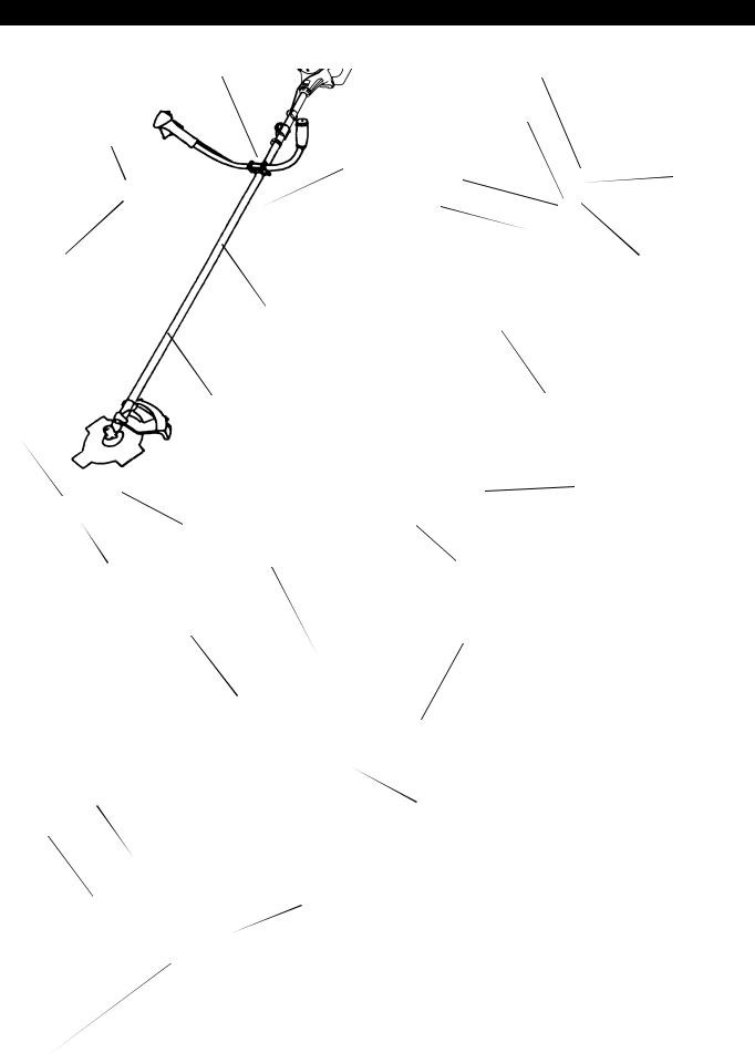
Names of parts
MS-26 U |
|
|
U Handle Type |
(12) |
(12) |
|
(9) |
(4) |
(4) |
|
|
|
|
|
|
(10) |
(8) |
|
(9) |
|
|
(10) |
|
(11) |
|
(11) |
|
(16) |
|
|
|
(13) |
|
|
|
|
(13) |
(15) |
|
|
(15) |
|
|
|
|
|
|
|
|
|
|
|
|
|
|
|
|
|
|
|
(14) |
(14) |
|
|
|
|
|
MS-26 C |
|
(17) |
(3) |
|
|
(18) |
|
Loop Handle Type |
|
|
|
|
|
||||
|
|
|
|
|
|||
(7) |
|
|
|
(19) |
|
|
|
|
|
|
|
|
|
|
|
|
|
|
|
|
|
|
|
|
|
|
|
|
|
|
Names of parts |
|
|
|
|
|
|
|
|
|
|
|
|
|
|
1 |
Fuel Tank |
|
|
|
|
|
|
|
|
|
|
|
|
|
|
2 |
Rewind Starter |
|
|
|
|
|
|
|
|
|
|
|
|
|
|
3 |
Air Cleaner |
|
|
|
|
|
|
|
|
|
|
|
|
|
|
4 |
I-O Switch (on/off) |
|
|
|
|
|
|
|
|
(21) |
|
|
|
|
5 |
Spark Plug |
|
|
|
|
|
|
|
||
|
|
|
|
6 |
Exhaust Muffler |
||
(5) |
|
|
|
|
|
|
|
|
|
(1) |
|
7 |
Clutch Case |
||
|
(22) |
|
|
|
8 |
Rear Grip |
|
|
|
|
|
|
|||
|
|
|
|
|
|
|
|
|
|
|
|
|
9 |
Hanger |
|
|
|
|
|
|
|
||
|
|
|
|
|
|
|
|
|
|
|
|
|
|
10 |
Handle |
|
|
|
|
|
|
|
|
|
|
|
|
|
|
11 |
Control Lever |
|
|
|
|
|
|
|
|
|
|
|
(6) |
|
|
12 |
Control Cable |
|
|
|
|
|
|
|
|
|
|
|
|
|
13 |
Shaft |
|
|
|
|
|
|
|
||
|
|
|
|
|
|
|
|
(20) |
|
|
|
|
14 |
Protector |
|
|
|
|
|
|
|
||
|
|
|
|
15 |
Gear Case |
||
|
|
|
|
|
|
|
|
|
|
|
|
|
|
16 |
Handle Holder |
|
|
|
|
|
|
|
|
|
|
|
|
|
|
17 |
Cutter Blade |
|
|
|
|
|
|
|
|
|
|
|
|
|
|
18 |
Nylon Cutting Head |
|
|
|
|
|
|
|
|
|
|
|
|
|
|
19 |
Fuel Filler Cap |
|
|
|
|
|
|
|
|
|
|
|
|
|
|
20 |
Starter Knob |
(2) |
|
|
|
|
|
|
|
|
|
|
|
21 |
Primer Pump |
||
|
|
|
|
|
|
|
|
|
|
|
|
|
|
22 |
Choke Lever |
|
|
|
|
|
|
|
|
9
Mounting the handle
CAUTION: Before doing any work on the brush cutter, always stop the engine and disconnect the spark plug connector from the spark plug. Always wear protective gloves!
CAUTION: Ensure you have reassembled the brush cutter completely before starting it.
For U Handle models
–Place the handle-fixing metal so that the handle with the control lever is positioned on the right (the right-hand grip side) when viewed from the engine side.
–Fit the groove of the handle-fixing material to the handle end. Temporarily fix the attached metal using the hexagon socket bolt provided.
–Adjust the handle to an easy-to-operate position, and securely tighten the four hexagon socket bolts uniformly on the right and left using an Allen key.
–Fit the control cable (together with the earth cord) to the handle with two clips
(1).
–Make sure the control cable does not loop at the handle bar section.
For Loop Handle models
–Fix the barrier to the left side of the equipment together with the handle to protect the operator.
–Do not adjust position of the loop handle too close to the control grip.
–Keep a distance of at least 250mm between the handle and the grip. (a distance collar is provided for this purpose.)
MS-26 U
(1)
MS-26 U
to Engine
MS-26 C
10
Mounting the protector
To meet the applicable safety standards, you must only use the tool/protector combinations indicated in the table.
Always use genuine DOLMAR cutter blades/nylon cutting head.
–The cutter blade must be well polished, and free of cracks or breakages. If the cutter blade hits against a stone during operation, stop the engine and check the blade immediately.
–Polish or replace the cutter blade every three hours of operation.
–If the nylon cutting head hits against a stone during operation, stop the engine and check the nylon cutting head immediately.
Star Blade |
Eddy Blade |
Protector for metal blades |
PART NO. 6258507600 |
PART NO. 6258507700 |
PART NO. 6258065000 |
|
|
|
CAUTION: The appropriate protectors must always be installed for your own safety and in order to comply with accident-prevention regulations. Operation of the equipment without the guard installed is prohibited.
– Fix the protector (1) to the clamp (3) with two M6 x 30 bolts (2).
–When using the string head, fit the protector (6) into the protector (1), and tighten them with two nuts (5) and two screws (4).
Nylon cutting head |
Protector for cord cutter |
PART NO. 6218016000 |
PART NO. 6258064000 |
![]() (2)
(2)
![]() (3)
(3)
![]() (1)
(1)
![]() (4)
(4)
(1)
(6)
(5)![]()
11
Mounting the cutter blade/nylon cutting head
The cutter blade or nylon cutting head can be replaced easily by first turning the equipment upside down.
–Insert the Allen key through the hole in the gear case and rotate the receiver washer (3) until it is locked with the Allen key.
–Loosen the nut (1) (left-hand thread) with the socket wrench, and remove the nut (1) and clamp washer (2).
With the Allen key still in place
–Mount the cutter blade onto the shaft so that the guide of the receiver washer
(3)fits in the arbor hole in the cutter blade. Install the clamp washer (2) and secure the cutter blade with the nut (1).
[Tightening torque: 13 - 23 N-m]
NOTE: Always wear gloves when handling the cutter blade.
NOTE: The cutter blade-fastening nut (with spring washer) is a consumable part. If there appears any wear or deformation on the spring washer, replace the nut.
NOTE: The clamp washer (2), and nut (1) are not necessary for mounting the nylon cutting head. The nylon head should go on top of the receiver washer (3).
– Screw the nylon cutting head onto the shaft.
– Make sure that the blade rotates counterclockwise.
(1) |
(2) |
(3)
Loosen |
Tighten |
|
Allen key
(3)![]()
Tighten
Loosen
Allen key
Rotation
12
Fuel/Refuelling
Handling fuel
Utmost care is required when handling fuel. Fuel may contain substances similar to solvents. Refuel either in a well ventilated room or outdoors. Do not inhale fuel vapors, and avoid any contact of fuel or oil with your skin.
Mineral oil products degrease your skin. Prolonged skin contact with these products will cause your skin to become extremely dry, which may result in various kinds of skin disease. In addition, allergic reactions may occur.
Eyes can be irritated by contact with oil. If oil comes into your eyes, immediately wash them with clear water. If your eyes are still irritated, see a doctor immediately.
Fuel and oil mixture
The brush cutter engine is a high-efficiency two-stroke engine. It runs on a mixture of fuel and two-stroke engine oil. The engine is designed for unleaded regular fuel with a min. octane value of 91 RON. If for any reason no such fuel is available, you can use fuel with a higher octane value. This will not affect the engine, but it may cause poor operating behaviour.
Similar problems will arise from the use of leaded fuel. To obtain optimum engine operation and to protect your health and the environment, use only unleaded fuel!
To lubricate the engine, add two-stroke engine oil (quality grade: JASO FC or ISO EGD) to the fuel. The engine has been designed to use the specified twostroke engine oil at mixture ratio of 50:1 to protect the environment.
Additionally, long service life accompanied by reliable operation and minimum emissions are guaranteed through the use of this mixture ratio. Reliable functioning of the brush cutter cannot be guaranteed unless this mixture ratio of 50:1 (specified 2-stroke engine oil) is strictly observed.
Correct mixture ratio:
Gasoline: Specified two-stroke engine oil = 50 : 1 or
Gasoline: Other manufacturer’s two-stroke engine oil = 25 : 1 recommended
NOTE: To prepare the fuel-oil mixture, first mix the entire oil quantity with half of the fuel required, then add the remaining fuel. Thoroughly shake the mixture before pouring it into the brush cutter tank. To ensure safe operation, do not add more engine oil than the specified amount. Doing so will only result in a higher production of combustion residues which pollute the environment and clog the exhaust channel in the cylinder as well as the muffler. In addition, the fuel consumption will rise and the performance will decrease.
Refuelling
The engine must be switched off.
–Thoroughly clean the area around the fuel filler cap (2) to prevent dirt from getting into the fuel tank (1).
–Unscrew the fuel filler cap (2) and fill the tank with fuel.
–Tightly screw on the fuel filler cap (2).
–Clean the screw fuel filler cap (2) and tank after refueling.
Storage of Fuel
Fuel cannot be stored for an unlimited period of time.
Purchase only the quantity required for a 4-week operating period. Only use approved fuel storage containers.
Observe the Safety Instructions on page 4.
Gasoline |
|
50:1 |
25:1 |
|
||
|
|
|
|
|
|
|
|
|
+ |
|
|
|
|
|
|
|
|
|
|
|
1,000 cm3 |
(1 liter) |
|
|
20 cm3 |
40 cm3 |
|
5,000 cm3 |
(5 liter) |
|
100 cm3 |
200 cm3 |
||
10,000 cm3 |
(10 liter) |
|
200 cm3 |
400 cm3 |
||
|
|
|
|
|
|
|
|
|
|
|
|
|
|
(1) |
(2) |
|
13
Correct handling
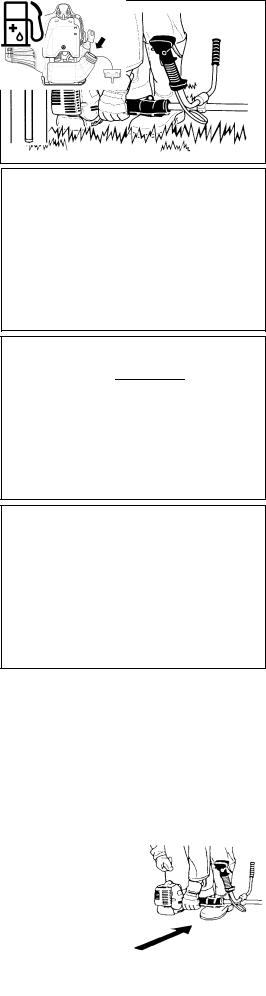
Attachment of shoulder strap
– Adjust the strap length so that the cutter blade is kept parallel with the ground.
Detachment
For MS-26 U
–In case of emergency, to detach the equipment from your body, strongly pull the emergency detachment lever (2) with your finger. This will detach the equipment sill from the body.
Be extremely careful to maintain control of the equipment at this time. Do not allow the equipment to be deflected toward you or anyone in your vicinity.
WARNING: Failure to maintain complete control of the equipment could result in serious injury or DEATH.
For MS-26 C
–In case of emergency, push the notches (1) at both sides, and detach the equipment.
Be extremely careful to maintain control of the equipment at this time. Do not allow the equipment to be deflected toward you or anyone in your vicinity.
WARNING: Failure to maintain complete control of the machine at all could result in serious injury or DEATH.
(2) ![]()
Hanger ![]()
(1) ![]()
Hanger ![]()
Important operating points/stopping the cutter/trimmer
Observe the applicable accident prevention regulations.
Starting
Move at least 3 m away from the area where you refuelled the equipment. Place the brush cutter on a clean piece of ground taking care that the cutting tool does not come into contact with the ground or any other objects.
Cold start |
(4) |
||
|
|||
– Push the I-O switch (1) in the direction shown by the arrow. |
|
||
– |
Grasp the handle (hand pressure activates the safety lock-off lever (2)). |
(3) |
|
– |
Press the throttle lever (3) and hold it down. |
||
|
|||
– Press the lock button (4) and release the control lever, and then release the |
(1) |
||
|
lock button (the lock button holds the throttle lever in the start-up position). |
||
|
|
(2) |
|
MS-26 U
(2)
(1)
(4)
(3)
MS-26 C
14

–First, place the equipment on the ground.
–Gently press the primer pump (5) repeatedly (7-10 times) until fuel comes into the primer pump.
–Close the choke lever (6).
Choke opening:
•Fully closed in cold temperatures or when the engine is cold
•Fully or half open for restart while the engine is still warm
–Firmly hold the clutch case with your left hand, as illustrated.
–Slowly pull the starter grip until you feel resistance, and then continue to pull sharply.
–Do not pull out the starter rope to its full extent, and do not allow the starter handle to retract by itself. Maintain control of the starter rope and ensure it retracts slowly.
–Repeat the starting operation until you hear the engine's initial ignitions.
– Depress the choke lever (6) ( |
) and pull the starter rope again until the |
engine starts. |
|
–As soon as the engine starts, immediately tap and release the throttle, to release the half-throttle lock and allow the engine to idle.
–Run the engine for approximately one minute at a moderate speed before applying full throttle.
(6)
CLOSE
(5)
OPEN
(6)
(5)
NOTE: – If you pull the starter handle repeatedly when the choke lever is in the at “![]() ” position, the engine will not start easily due to excessive fuel intake.
” position, the engine will not start easily due to excessive fuel intake.
–If excessive fuel intake occurs, remove the spark plug and pull the starter handle slowly to remove excess fuel. Also, dry the electrode section of the spark plug.
Caution during operation:
If the throttle lever is opened fully during a no-load operation, the engine revolutions increase over 10,000 min-1. Never operate the engine at a
higher speed than required, and keep the revolutions at an approximate speed of 6,000 - 8,000 min-1. CAUTION: Always reduce the engine revolutions when the equipment is not being used for work.
Operating the equipment at high revolutions when not being used for work will shorten the lifespan of the equipment.
Warm start
–Follow the instructions for cold start above, except without moving the choke lever (choke lever remains in the down position (![]() )).
)).
Stopping
–Release the throttle lever (3) fully, and when the engine rpm has lowered, push the I-O switch (1) to "O" position to stop the engine.
–Be aware that the cutting head may not stop immediately, and always allow it to slow down and stop fully by itself.
(3)(1)
MS-26 U
(1)
(3)
MS-26 C
15
ADJUSTMENT OF LOW-SPEED REVOLUTIONS (IDLING)
The cutter blade or the nylon cutting head should not rotate when the control lever is fully released. If necessary, adjust the idling rpm using the idling adjustment screw.
Checking the Idling speed
–The idling speed should be set to 3,000 min-1.
If necessary, adjust the idling speed using the idling screw (the blade or the nylon cutting head must not turn when the engine is idling).
Tightening the idling screw (1) increases the engine revolutions, whereas loosening the idling screw reduces the engine revolutions.
(1)
Slow High
Resharpening the cutting tool
CAUTION: The cutting tools listed below must only be resharpened by an authorized facility. Manual resharpening will result in imbalances of the cutting tool, which will cause vibrations and damage to the equipment.
– cutter blade (star blade (4 teeth), eddy blade (8 teeth))
A professional resharpening and balancing service is provided by Authorized Service Agents.
NOTE: To increase the service life of the cutter blade (star blade, eddy blade) the blade may be turned over to allow both cutting edges to wear.
NYLON CUTTING HEAD
The nylon cutting head is a dual string trimmer head capable of both automatic and bump & feed mechanisms.
The nylon cutting head will automatically feed out the proper length of nylon cord by the changes in centrifugal force caused by increasing or decreasing rpms. However, to cut soft grass more efficiently, bump the nylon cutting head against the ground to feed out extra cord as shown in operation section.
Operation
–Increase the nylon cutting head speed to approx. 6,000 min-1.
Nylon cord will not feed out correctly at lower speeds (under 4,800 min-1).
–The most effective cutting area is shown by the shaded area in the diagram to the right.
If the nylon cord does not feed out automatically, follow the instructions below:
1.Release the throttle lever so that the engine idles, and then squeeze the throttle lever fully. Repeat this procedure until the nylon cord feeds out to the proper length.
2.If the nylon cord is too short to feed out automatically using the procedure above, bump the knob of the nylon cutting head against the ground to feed out the nylon cord.
3.If the nylon cord does not feed out using procedure 2, rewind/replace the nylon cord by following the procedures described under “Replacing the nylon cord”.
Most effective cutting area
Idle speed |
Full speed |
Knob
Replacing the nylon cord
–Stop the engine.
–Press the housing latches inward to lift off the cover, then remove the spool.
|
Cover |
|
Latches |
Press |
Press |
|
16
–Hook the center of new nylon cord into the notch in the center of the spool, with one end of the cord extending about 80mm (3-1/8") more than the other. Then wind both ends firmly around the spool in the direction of the head rotation (left-hand direction indicated by LH and right-hand direction by RH on the side of the spool).
–Wind all but about 100mm (3-15/16") of the cords around the spool, leaving the ends temporarily hooked through the notch on the side of the spool.
–Mount the spool in the housing so that the grooves and protrusions on the spool match up with those in the housing. Mount the spool so that the writing on the spool is visible from above. Next, unhook the ends of the cords from their temporary position, and feed the cords through the eyelets so that they protrude from the housing.
–Align the protrusion on the underside of the cover with the slots of the eyelets. Then push cover firmly onto the housing to secure it.
Spool |
80mm (3-1/8") |
For left hand rotation
Spool
100mm (3-15/16")
Notches
Eyelets
Cover
Protrusion
Slot of eyelet
Servicing instructions
Servicing instructions
CAUTION: Before performing any type of maintenance work on the Brush cutter, always switch off the motor and detach the plug cap from the spark plug (see “checking the spark plug”).
Always wear protective gloves.
CAUTION: Never remove the recoil starter yourself. Doing so may cause an accident. This procedure should only be performed by an Authorized Service Agent.
To ensure a long service life and to avoid any damage to the equipment, perform the following maintenance operations regularly.
Daily inspection and maintenance
–Before operation, check the equipment for loose screws or missing parts. Pay particular attention to the tightness of the cutter blade or nylon cutting head.
–Before operation, always check to make sure that the cooling air passage and cylinder fins are not clogged. Clean them if necessary.
–Perform the following maintenance operations daily after use:
•Clean the Brush cutter externally and inspect it for damage.
•Clean the air filter. When working under extremely dusty conditions, clean the filter several times a day.
•Check the blade or the nylon cutting head for damage and make sure it is firmly mounted.
•Check that there is sufficient difference between the idling and operating speeds to ensure the cutting tool is at a standstill while the engine is idling (if necessary, reduce the idling speed).
If the cutting tool continues to rotate during engine idling, consult your nearest Authorized Service Agent.
–Check that the I-O switch, the lock-off lever, the control lever, and the lock button are all functioning correctly.
17
Cleaning the air cleaner (filter) |
|
|
(4) |
||
– Unscrew screw (1). |
||
|
||
– Turn the choke lever (4) to the fully closed side, and keep the carburetor away |
|
|
from any dust or dirt. |
(1) |
|
– Remove the air cleaner cover (3). |
||
|
||
– Remove the sponge element (2), wash it in lukewarm water and dry it |
|
|
completely. |
|
|
– After cleaning, put back the air cleaner cover (3) and fasten it with screw (1). |
|
|
NOTE: If there is excessive dust or dirt adhering to the air cleaner, clean it every |
(2) |
|
day. A clogged air cleaner may make it difficult or impossible to start the |
(3) |
|
engine, or may increase the engine rotational speed. |
|
|
|
Checking the spark plug
–Only use the supplied universal wrench to remove or to install the spark plug.
–The gap between the two electrodes of the spark plug should be 0.6-0.7mm (0.024”-0.028”). If the gap is too wide or too narrow, adjust it. If the spark plug is clogged with carton or dirty, clean it thoroughly or replace it.
CAUTION: Never touch the spark plug connector while the engine is running (danger of high voltage electric shock).
0.6mm-0.7mm (0.024”-0.028”)
Supply of grease to gear case |
|
|
Grease hole |
||
– Supply grease (Shell Alvania 3 or equivalent) to the gear case through the |
||
|
||
grease hole every 30 hours. (Genuine DOLMAR grease may be purchased |
|
|
from your DOLMAR dealer.) |
|
|
|
|
Suction head in the fuel tank
–The fuel filler (5) of the suction head is used to supply the fuel required by the carburetor.
– Visually inspect the fuel filter periodically. To inspect the filter, open the tank |
(5) |
cap, use a wire hook and pull out the suction head through the tank opening. |
|
Replace the filter if it has hardened, become particularly dirty, or clogged. |
|
– Insufficient fuel supply may result in the maximum permissible speed being |
|
exceeded. Therefore, the fuel filter must be replaced at least quarterly to |
|
ensure satisfactory fuel supply to the carburetor. |
|
Any other maintenance or adjustment work that is not described in this manual must only be performed by Authorized Service Agents.
18
Storage
–When storing the equipment for a long period of time, drain all the fuel from the fuel tank and carburetor. To do this, simple drain all of the fuel from the fuel tank. Dispose of the drained fuel in accordance with local applicable laws.
–Remove the spark plug and add a few drops of oil into the spark plug hole. Then, pull the starter gently so that oil coats the inside of the engine, then tighten the spark plug.
– Clean any dirt or dust from the cutter blade and outside of the engine, and |
|
|
|
|
Drain fuel |
||||
|
Humidity |
|||
wipe them with a oil-immersed cloth. Store the equipment in a dry place. |
|
|
|
|
|
|
|
Maintenance schedule
General |
Engine assembly, screws and nuts |
Visual inspection for damage and tightness |
|
Check for general condition and security |
|
|
|
|
|
|
|
After each refuelling |
Control lever |
Functional check |
|
I-O switch |
Functional check |
|
|
|
Daily |
Air filter |
To be cleaned |
|
Cooling air duct |
To be cleaned |
|
Cutting tool |
Check for damage and sharpness |
|
Idling speed |
Inspection (cutting tool must not move) |
|
|
|
Weekly |
Spark plug |
Inspection, replace if necessary |
|
Muffler |
Inspect, and clean the opening if necessary |
|
|
|
Quarterly |
Suction head |
To be replaced |
|
Fuel tank |
To be cleaned |
|
|
|
Shutting down procedure |
Fuel tank |
Empty fuel tank |
|
Carburetor |
Operate until engine runs out of fuel |
|
|
|
Troubleshooting
Fault |
System |
Observation |
Cause |
|
|
|
|
Engine doesn't start, or is |
Ignition system |
Ignition spark O.K. |
Fault in fuel supply or compression system, mechanical |
difficult to start |
|
|
defect |
|
|
No ignition spark |
I-O switch operated, wiring fault or short circuit, spark |
|
|
|
plug or connector defective, ignition module faulty |
|
Fuel supply |
Fuel tank filled |
Incorrect choke position, carburetor defective, fuel |
|
|
|
supply line bent or blocked, fuel dirty. |
|
Compression |
No compression when |
Cylinder bottom gasket defective, crankshaft seals |
|
|
pulled over |
damaged, cylinder or piston rings defective or improper |
|
|
|
sealing of spark plug |
|
Mechanical fault |
Starter not engaging |
Broken starter spring, broken parts inside the engine |
Warm start problems |
|
Tank filled. Ignition |
Carburetor contaminated, must be cleaned |
|
|
spark O.K. |
|
Engine starts but dies |
Fuel supply |
Tank filled |
Incorrect idling adjustment, carburetor contaminated |
|
|
|
Fuel tank vent defective, fuel supply line interrupted, |
|
|
|
cable or I-O switch faulty |
Insufficient performance |
Several systems |
Engine idling poor |
Air filter contaminated, carburetor contaminated, muffler |
|
may simultaneously |
|
clogged, exhaust duct in the cylinder clogged |
|
be affected |
|
|
|
|
|
|
19

Merci pour votre achat de cette débroussailleuse/taille-bordure de DOLMAR. Les débroussailleuses/taille-bordures DOLMAR sont des produits développés après de nombreuses années d'apprentissage et d'expérience et d'un programme de développement détaillé.
Veuillez lire ce manuel complètement afin de vous assurer d'obtenir la meilleure des performances possibles et des résultats remarquables que peut vous procurer votre débroussailleuse/taille-bordure DOLMAR.
|
Français |
Table des matières |
Page |
Symboles .................................................................... |
20 |
Instructions de sécurité ............................................... |
21 |
Données techniques MS-26 U, MS-26 C.................... |
25 |
Noms des pièces......................................................... |
26 |
Montage de la poignée ............................................... |
27 |
Montage du dispositif de protection ............................ |
28 |
Montage du couteau/tête à fil en nylon ....................... |
29 |
Carburant/Ravitaillement............................................. |
30 |
Manutention correcte .................................................. |
31 |
Points de fonctionnement importants /arrêt de |
|
la débroussailleuse/taille-bordure ............................... |
31 |
Réaffûtage du dispositif de coupe............................... |
33 |
Instructions d'entretien ................................................ |
34 |
Entreposage................................................................ |
36 |
Symboles
Vous avez besoin de prendre note des symboles suivants lors de la lecture du manuel d'instructions.
Lire le manuel d'instructions
Usez d'attention et de soins tout particulier
Interdit
Restez à distance
Danger d'objets volants
Ne fumez pas
Pas de flammes nues
Portez des gants de protection
Rebond
Eloignez les personnes et les animaux du lieu de travail
Portez des bottes de sécurité avec des semelles antidérapantes. Les bottes de sécurité à doigts de pieds métalliques sont recommandées.
Portez des lunettes de protection et des protègeoreilles
(que pour le taille-bordure)
Portez un casque protecteur, des lunettes de protection et des protège-oreilles
(que pour la débroussailleuse)
N’utilisez pas de lames métalliques (que pour le taille-bordure)
Vitesse d'outil maximum autorisé
Surfaces brûlantes - Brûlures aux doigts ou aux mains
Mélange d'huile et d'essence
Démarrage manuel du moteur
Arrêt d'urgence
Premier secours
Recyclage
SOUS TENSION/DEMARRAGE
HORS TENSION/ARRET
20
Instructions de sécurité
Instructions générales
–Il est vivement recommandé à toute personne désirant utiliser correctement l'outil de lire et de comprendre en entier le présent manuel d'instructions afin de se familiariser avec l'utilisation de la débroussailleuse/taille-bordure.
L'utilisation de cet équipement sans une bonne connaissance de son fonctionnement peut entraîner des blessures graves non seulement à vousmême mais aussi aux autres.
–Ne prêtez votre débroussailleuse/taille-bordure qu'à des gens qui ont une expérience éprouvée de ces débroussailleuses/taille-bordures. Joignez toujours le présent manuel en cas de prêt
–Si c'est la première fois que vous utilisez une débroussailleuse/taille-bordure à moteur, consultez votre revendeur pour les instructions de base.
–Il est interdit aux enfants et à toute personne en dessous de 18 ans d’utiliser la débroussailleuse/taille-bordure Les personnes de plus de 16 ans peuvent l'utiliser à des fins de formation, mais uniquement sous la supervision d'un formateur agréé.
–Utilisez les débroussailleuses/taille-bordures avec le plus grand soin et attention.
–N'utilisez la débroussailleuse/taille-bordure que si vous êtes en bonne condition physique. Effectuez tout le travail avec calme et prudence. Vous êtes responsable de ceux qui se trouvent autour de vous.
–N'utilisez jamais la débroussailleuse/taille-bordure après avoir consommé de l'alcool ou pris des médicaments, ou si vous vous sentez fatigué ou malade.
Utilisation prévue de l'équipement
–L'usage de la débroussailleuse/taille-bordure est prévu pour couper de l’herbe; taillis et autres petits arbustes et, ne doit jamais être utilisée pour d'autres fins telles que le délignage ou tailler des haies car cela peut causer des blessures.
Dispositifs de protection individuelle
–Portez toujours des vêtements qui sont à la fois fonctionnel et approprié au travail, c'est-à-dire bien ajusté mais pas trop serré afin de ne pas causer de mouvement inconfortable. Ne portez pas de bijoux ou de vêtements qui pourraient s'emmêler dans les taillis ou les petits arbustes.
–L'équipement de protection suivant ainsi que les vêtements de protection doivent être utilisés tandis que vous utilisez la débroussailleuse/taille-bordure afin d'éviter des blessures au pied, à la main, aux yeux et à la tête ainsi que pour protéger votre ouïe durant l'utilisation.
–Portez toujours un casque où il y a un risque que des objets puissent tomber Le casque de protection (1) doit être vérifié à des intervalles réguliers pour d'éventuels dommages et doit être remplacé au plus tard d'ici les 5 ans. N'utilisez que des casques de protection agréés.
–La visière (2) du casque (ou alternativement les lunettes) protège le visage des débris et des pierres qui volent. Durant l'utilisation de la débroussailleuse/ taille-bordure, portez toujours des lunettes ou une visière afin d'empêcher toute blessure aux yeux .
–Portez un équipement de protection antibruit adéquate afin d'éviter tout infirmité (coquilles antibruit (3), bouchons d'oreille etc.).
–Des vêtements de travail (4) protègent contre les débris et les pierres qui volent.
Nous recommandons fortement que vous portiez vos vêtements de travail.
–Des gants spéciaux (5) en cuir épais font partie de l'équipement prescrit et doivent toujours être portés durant l'utilisation de la débroussailleuse/taillebordure.
–Quand vous utilisez la débroussailleuse/taille-bordure, portez toujours des chaussures robustes (6) avec une semelle anti-dérapante. De telles chaussures protègent contre les blessures et assurent une bonne assise.
Démarrage de la débroussailleuse
–Eloignez les personnes et les enfants du lieu de travail à une distance minimum de 15 mètres et aussi faites attention aux animaux qui pourraient se trouver à proximité.
–Avant utilisation,vérifiez toujours que la débroussailleuse/taille-bordure puisse être utilisée en toute sécurité :
Vérifiez que le dispositif de coupe est sûr, que le levier de manœuvre peut être facilement utilisé, et que le verrou du levier de manœuvre fonctionne bien.
–La rotation du dispositif de coupe au repos est interdite. Vérifiez avec votre revendeur si vous pensez que l'équipement peut avoir besoin d'un réglage. Vérifiez que les poignées sont propres et sèches et que l'interrupteur de marche/arrêt fonctionne correctement.
(1)
(2)
(3)
(4)
(5) (6)
Diagramme
15 mètres
21
–Ne démarrez la débroussailleuse/taille-bordure qu'en conformité avec les instructions. N'utilisez pas d'autres méthodes pour démarrer le moteur !
–N'utilisez la débroussailleuse/taille-bordure et les outils que pour des besoins spécifiés.
–Ne démarrez la débroussailleuse/taille-bordure qu'après que l'équipement ait été entièrement assemblé. N'utilisez l'équipement qu'après avoir fixé les accessoires appropriés !
–Avant de démarrer assurez-vous que l'outil de coupe n'est pas en contact avec des objets durs tels que des branches, pierres etc. et qu'il tournera au démarrage.
–Eteignez de suite le moteur s'il y a un problème de moteur qui se produit
–Si l'outil de coupe frappe des pierres ou d'autres objets durs, éteignez de suite le moteur et examinez l'outil de coupe.
–Examinez le dispositif de coupe à intervalles réguliers courts pour voir s'il n'a pas subi de dommages (Examinez pour des fissures capillaires en utilisant le test de tapping).
–N'utilisez la débroussailleuse/taille-bordure qu'après avoir mis et réglé la sangle du harnais à la longueur correcte. Il faut régler la sangle du harnais à la taille de l'utilisateur et l'attacher afin d'empêcher la fatigue durant l'utilisation de l'équipement. Ne tenez jamais la débroussailleuse d'une seule main durant l'utilisation.
–Durant l'utilisation, tenez toujours la débroussailleuse/taille-bordure avec les deux mains.
Assurez-vous toujours que vous avez une bonne assise.
–Utilisez la débroussailleuse/taille-bordure de façon à éviter l'inhalation des gaz d'échappement. Ne faites jamais tourner le moteur dans un espace fermé tel que l'intérieur d'une pièce (risque d'empoisonnement par les gaz). Le monoxyde de carbone est un gaz sans odeur.
–Eteignez toujours le moteur au repos, ou si vous avez l'intention de laisser la débroussailleuse/taille-bordure sans surveillance, et mettez-la dans un endroit sûr afin d'empêcher de blesser d'autres personnes et d'endommager l'équipement.
–Ne mettez jamais la débroussailleuse/taille-bordure chaude sur de l'herbe sèche ou sur d'autres matériaux combustibles.
–Il faut toujours que le dispositif de coupe soit équipé de sa protection appropriée.
N'utilisez jamais la débroussailleuse sans cette protection !
–Il faut utiliser toutes les installations protectives et les protections fournies avec l'équipement durant l'utilisation.
–Ne faites jamais fonctionner le moteur si le tuyau d'échappement est défectueux.
–Eteignez le moteur durant le transport.
–Durant le transport sur de longues distances, utilisez toujours l'équipement de protection de l'outil inclus.
–Assurez-vous que la débroussailleuse/taille-bordure est sécurisée durant le transport pour éviter des fuites de carburant.
–Quand vous transportez la débroussailleuse/taille-bordure, assurez-vous que le réservoir de carburant est complètement vide.
–Quand vous déchargez la débroussailleuse/taille-bordure d'un camion ou d'un autre véhicule analogue, ne laissez jamais tomber le moteur sur le sol, ce qui pourrait endommager gravement le réservoir de carburant.
–A moins d'une urgence, ne laissez jamais tomber ou couler la débroussailleuse/taille-bordure sur le sol ce qui pourrait l'endommager gravement.
–Soulevez toujours l'ensemble de l'équipement à partir du sol lorsque vous la déplacez. Traînez l'équipement sur son réservoir de carburant est extrêmement dangereux et peut résulter en des fuites qui peuvent causer un incendie.
Ravitaillement
–Eteignez le moteur lors du ravitaillement, éloignez-le des flammes nues et ne fumez pas.
–Assurez-vous que les produits d'huile minérale n'entrent pas en contact avec la peau. N'inhalez pas les vapeurs de carburant. Portez toujours des gants de protection durant le ravitaillement. Changez et nettoyez les vêtements de protection à intervalles réguliers.
–Afin de prévenir toute contamination de la terre (protection environnementale), assurez-vous de ne pas renverser de carburant ou d'huile sur le sol. Si vous renversez du carburant nettoyez la débroussailleuse/taille-bordure immédiatement.
–Assurez-vous que le carburant n'entre pas en contact avec vos vêtements. Si le carburant entre en contact avec vos vêtements changez-les immédiatement afin d'empêcher tout incendie.
–Vérifiez le bouchon du réservoir à intervalles réguliers pour vous assurer qu'il est installé en toute sécurité et ne fuit pas.
•Au repos
•Transport
•Ravitaillement
•Maintenance
•Remplacement d'outil
|
|
|
|
|
|
|
|
|
|
|
|
|
|
|
|
|
|
|
|
|
|
|
|
|
|
|
|
|
|
|
|
|
|
|
|
|
|
|
|
|
|
|
|
s |
|
|
|
|
|
|
|
|
|
|
|
|
|
|
|
|
e |
|
|
|
|
|
|
|
r |
|
|
|
|
|
|
|
|
t |
|
|
|
|
|
|
|
è |
|
|
|
|
|
|
|
m |
|
|
|
|
|
|
|
|
3 |
|
|
|
|
|
|
|
|
|
|
|
|
|
|
|
|
|
|
|
|
|
|
22

–Serrez soigneusement le bouchon du réservoir de carburant. Une fois que le ravitaillement est terminé, déplacez-le à un endroit éloigné d'au moins de
3 mètres d'où vous l'avez rempli avant de démarrer le moteur.
–Ne remplissez jamais dans un espace fermé tel que l'intérieur d'une pièce. Ce faisant cela peut causer une explosion suite à l'accumulation des vapeurs de carburant au niveau du sol.
–Transportez et stockez uniquement dans des conteneurs agréés. Assurezvous que les enfants n'accèdent pas au carburant.
Mode d'emploi
–N'utilisez la débroussailleuse/taille-bordure qu'avec une bonne visibilité et un bon éclairage. Durant la saison d'hiver, faites attention aux zones glissantes ou mouillées telles que des zones verglacées ou recouvertes de neige (risque de glisser). Assurez-vous toujours que vous êtes bien sur une bonne assise.
–Ne coupez jamais à une hauteur supérieure aux épaules.
–Ne vous tenez jamais sur une échelle lorsque vous utilisez la débroussailleuse/taille-bordure.
–Ne grimpez jamais dans les arbres lorsque vous utilisez la débroussailleuse/ taille-bordure.
–Ne travaillez jamais sur des surfaces instables.
–Enlevez le sable, les pierres, les clous etc. trouvés à l'intérieur du périmètre de travail.
Des objets étrangers peuvent endommager l'outil de coupe et peuvent causer des rebonds dangereux.
–Avant de commencer à couper, assurez-vous que le dispositif de coupe a atteint son régime de croisière.
Rebond
–Quand vous utilisez la débroussailleuse, des rebonds incontrôlés peuvent se produire.
–Des rebonds se produire fréquemment quand vous essayez de couper avec la section de l'heure de 12 à 2 de la lame.
–N'appliquez jamais la section de l'heure de 12 à 2 de la lame de la débroussailleuse.
–N'appliquez jamais cette section de la lame de la débroussailleuse à des objets solides, tels que des arbustes ou des arbres etc. qui ont un diamètre de plus de 3 cm. Ce faisant cela entraînera la débroussailleuse à dévier avec une grande force, ce qui est extrêmement dangereux et peut causer des blessures.
Prévention des rebonds
Pour éviter des rebonds, souvenez-vous ce qui suit :
–L'utilisation de la section de l'heure de 12 à 2 de la lame est extrêmement dangereux, surtout lors de l'utilisation d'outils de coupe du métal.
–Les opérations de coupe utilisant les sections de 11 à 12 et de 2 à 5 de l'heure de la lame de la débroussailleuse ne doivent être effectués que par des opérateurs formés et expérimentés, et puis qu'à leur propre risque.
La section de coupe optimale pour une coupe facile avec presque aucun rebond est entre la section d'horloge 8 à 11 de la lame.
Dispositifs de coupe
Assurez-vous d'utiliser le dispositif de coupe correct pour chaque travail particulier.
Pour couper des matériels épais tels que de mauvaises herbes, de l'herbe haute, des taillis, des petits arbustes, du sous-bois, du fourré etc. (épaisseur max. diamètre de 2 cm). Le fauchage doit être effectué avec des mouvements de droite à gauche de la débroussailleuse en demi-cercles égaux. (de la même façon que vous utilisez une faux).
Instructions d’entretien
–Avant de commencer le travail vérifiez toujours la condition du couteau, en particulier ses dispositifs de protection et le harnais. Il faut examiner avec une attention toute particulière les couteaux, qui doivent être bien aiguisés.
–Il faut mettre sous tension le moteur et enlever le connecteur de bougies lorsque vous remplacez ou aiguisez les dispositifs de coupe, et aussi quand vous nettoyez le couteau et le dispositif de coupe.
Attention :
Rebond
Diagramme
Diagramme
23

Ne jamais redresser ou souder des dispositifs de coupes endommagés.
–Utilisez la débroussailleuse/taille-bordure avec aussi peu de bruit et de contamination que possible. En particulier,vérifiez que le carburateur est fixé correctement.
–Nettoyez la débroussailleuse/taille-bordure à des intervalles réguliers et vérifiez que toutes les vis ainsi que les écrous sont bien serrés.
–Ne jamais entretenir ou stocker la débroussailleuse/taille-bordure à proximité de flammes.
–Toujours rangez la débroussailleuse/taille-bordure dans des pièces fermées, avec le réservoir de carburant complètement vide.
Observez les instructions de prévention d'accident pertinentes publiées par les associations commerciales et les compagnies d'assurance .
N'effectuez aucune modification sur la débroussailleuse/taille-bordure , car ce faisant vous risquez de compromettre votre sécurité.
L'exécution de l'entretien ou de réparations par l'utilisateur est limitée aux activités décrites dans le mode d'emploi. Tout autre travail doit être fait par un agent d'entretien agréé. N'utilisez des pièces de rechange et des accessoires d'origine fournis par DOLMAR.
L'utilisation d'accessoires et d'outils non agréés peut résulter en une augmentation des risques d'accidents.
DOLMAR n'acceptera aucune responsabilité pour des accidents ou des dommages causés par l'utilisation de dispositifs de coupe, d'appareils de montage de dispositifs de coupe ou d'accessoires.
Premier secours
En cas d'accident, assurez-vous qu'une mallette de premier secours se trouve à proximité des opérations de coupe. Remplacez immédiatement tout article pris dans la mallette de premier secours.
Lorsque vous demandez de l'aide, veuillez donner les renseignements suivants :
–Lieu de l'accident
–Que s'est-il passé ?
–Nombre de personnes blessées
–Les sortes de blessures
–Votre nom
Emballage
La débroussailleuse/taille-bordure DOLMAR est livrée dans deux boîtes en carton de protection pour empêcher tout dommage lors du transport. La boîte en carton est un matériel brut de base et est par conséquent réutilisable ou convenable pour le recyclage (recyclage des déchets de papiers).
DECLARATION DE CONFORMITE CE
Modèles; MS-26 U, MS-26 C
Nous déclarons, sous notre entière responsabilité, que ce produit répond aux normes suivantes de documents normalisés ISO11806, EN55012 conformément aux Directives du Conseil, 89/392/EEC, amendé 98/37/EEC, 93/68/EEC, 89/336/EEC, amendé 92/31/EEC
Puissance sonore mesurée : 111,7 dB
Puissance sonore garantie : 114 dB
Ces niveaux de puissance sonore ont été mesurés conformément à la Directive du Conseil, 2000/14/EC.
Procédure d'évaluation de la conformité : Annexe V.
CE2008
Tamiro Kishima |
Rainer Bergfeld |
Directeur général |
Directeur général |
Fabricant responsable :
Makita Corporation
3-11-8, Sumiyoshi-cho, Anjo, Aichi, JAPON Représentant agréé en Europe :
DOLMAR Gmbh
Jenfelder Str. 38, 22045 Hamburg,Germany
24

Données techniques MS-26 U, MS-26 C
|
Modèle |
|
MS-26 U |
|
MS-26 C |
|
|
|
|
|
|
|
|
Poignée en U |
|
Poignée en boucle |
|
|
|
|
|
||
|
|
|
|
|
|
Dimensions : longueur x largeur x hauteur (sans la lame de |
mm |
1 770 x 630 x 410 |
|
1 770 x 315 x 235 |
|
coupe) |
|
|
|||
|
|
|
|
|
|
|
|
|
|
|
|
Masse (sans la protection plastique et la lame de coupe) |
kg |
5,0 |
|
4,8 |
|
|
|
|
|
|
|
Volume (réservoir de carburant) |
L |
|
0,6 |
||
|
|
|
|
|
|
Déplacement du moteur |
|
cm3 |
|
25,7 |
|
Performance du moteur maximum |
kw |
0,83 à 8 000 min-1 |
|||
Vitesse du moteur à la vitesse de l'axe rmax. recommandée |
min-1 |
|
10 000 |
||
|
|
|
|
||
Vitesse de l'axe maximum (correspondant) |
min-1 |
|
7 400 |
||
|
|
|
|
||
Consommation de carburant maximum |
kg/h |
|
0,431 |
||
|
|
|
|
||
Consommation de carburant spécifique maximum |
g/kWh |
|
487 |
||
|
|
|
|
|
|
Vitesse à vide |
|
min-1 |
|
3 000 |
|
|
|
|
|
||
Vitesse d'engagement de l'engrenage |
min-1 |
|
4 000 |
||
|
|
|
|
|
|
Carburateur |
|
type |
|
WALBRO WYC |
|
|
|
|
|
||
Système d'allumage |
|
type |
Allumage à semi-conducteur |
||
|
|
|
|
|
|
Bougie d’allumage |
|
type |
|
NGK BPMR7A |
|
|
|
|
|
|
|
Ecart d'électrode |
|
mm |
|
0,6 - 0,7 |
|
|
|
|
|
|
|
Vibration selon la norme |
Poignée droite (Prise arrière) |
m/s2 |
3,8 |
|
5,3 |
|
|
|
|
|
|
ISO 228671) |
Poignée gauche (Prise avant) |
m/s2 |
3,9 |
|
4,3 |
|
|
||||
Moyenne du niveau de pression acoustique selon la norme |
dB |
|
98,2 |
||
ISO 228681) |
|
|
|||
|
|
|
|
|
|
Moyenne du niveau de puissance sonore selon la norme |
dB |
|
108,5 |
||
ISO 228681) |
|
|
|||
|
|
|
|
|
|
Carburant |
|
|
Gaz mélangé (essence : Huile moteur deux temps de marque |
||
|
|
|
DOLMAR = 50:1) |
||
|
|
|
|
||
|
|
|
|
|
|
Rapport de vitesse |
|
|
|
14/19 |
|
|
|
|
|
|
|
1) Les données prennent également en compte le ralenti et l'accélération ou des modes de fonctionnement d'accélération des gaz très ouverts.
25
Noms des pièces
MS-26 U
Type de poignée en U (12)
(9)
(4)
(11)
(13)
(15)
(14)
(17)
(7)
(21)
(5)
(22)
(20)
(2)
|
(12) |
|
(4) |
(10) |
(8) |
(9) |
|
(10) |
|
|
(11) |
(16)
|
(13) |
|
|
(15) |
|
|
(14) |
|
|
MS-26 C |
|
(3) |
Type de poignée en delta |
|
(18) |
||
|
|
|
(19) |
|
|
|
|
|
|
|
|
|
|
|
Noms des pièces |
|
|
|
|
|
|
|
|
1 |
Réservoir de carburant |
|
|
|
|
|
|
|
|
2 |
Démarreur à rappel |
|
|
|
|
|
|
|
|
3 |
Filtre à air |
|
|
|
|
|
|
|
|
4 |
Interrupteur E-S (marche/arrêt) |
|
|
|
|
|
|
|
|
5 |
Bougie d’allumage : |
|
|
|
|
|
|
|
|
6 |
Silencieux d'échappement |
|
|
|
|
|
|
(1) |
|
7 |
Carter d'embrayage |
|
|
|
|
|
|
|
8 |
Prise arrière |
|
|
|
|
||
|
|
|
|
|
|
|
|
9 |
Crochet de suspension |
|
|
|
|
|
|
|
|
10 |
Poignée |
|
|
|
|
|
|
|
|
11 |
Levier de contrôle |
|
|
|
|
|
(6) |
|
|
12 |
Câble de contrôle |
|
|
|
|
|
|
|
13 |
Arbre |
|
|
|
|
||
|
|
|
|
|
|
|
|
14 |
Protecteur |
|
|
|
|
|
|
|
|
15 |
boîte d'engrenage |
|
|
|
|
|
|
|
|
16 |
Support de poignée |
|
|
|
|
|
|
|
|
17 |
Couteau |
|
|
|
|
|
|
|
|
18 |
Tête à fil en nylon |
|
|
|
|
|
|
|
|
19 |
Bouchon de réservoir de carburant |
|
|
|
|
|
|
|
|
20 |
Bouton de démarrage |
|
|
|
|
|
|
|
|
21 |
Poire d'amorçage |
|
|
|
|
|
|
|
|
22 |
Levier de l’étrangleur |
|
|
|
|
|
26
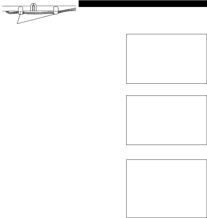
Montage de la poignée
ATTENTION : Avant de faire un travail quelconque sur le taille-bordure, il faut toujours arrêter le moteur et débrancher le connecteur des bougies. Portez toujours des gants de protection !
ATTENTION : Assurez-vous que vous avez réassembler complètement le taille-bordure avant de le démarrer.
Pour les modèles de poignée en U
–Positionnez le métal de fixation de poignée de sorte que la poignée avec le levier de manœuvre est positionné sur la droite (le côté de la prise droite) vue du côté du moteur.
–Montez la rainure du matériel de fixation de poignée au bout de la poignée. Temporairement fixez le métal attaché en utilisant le boulon à tête creuse hexagonale fourni.
–Réglez la poignée à une position facile à opérer, et serrez fermement les quatre boulons à tête creuse hexagonale de manière uniforme à droite et à gauche en utilisant la clé Allen.
–Montez le câble de contrôle (ensemble avec le fil de mise à la terre) sur la poignée avec deux attaches (1).
–Assurez-vous que le câble de contrôle ne s'enroule pas à la section de la barre de la poignée.
Pour les modèles de poignée en U
–Montez la barrière sur le côté gauche de l'équipement ensemble avec la poignée pour protéger l'utilisateur.
–Ne réglez pas trop près la position de la poignée à guidon de la prise de manœuvre.
–Gardez une distance d'au moins de 250 mm entre la poignée et la prise. (un collier de distance est fourni pour cette fin.)
MS-26 U
(1)
MS-26 U
vers le moteur
MS-26 C
27

Montage du dispositif de protection
Pour satisfaire les normes de sécurité en vigueur, vous ne devez utiliser que les combinaisons outil/dispositif de protection indiquées dans le tableau.
Utilisez toujours des couteaux/têtes à fil de nylon d'origine DOLMAR.
–Le couteau doit être bien aiguisé, et sans fissures ou cassures. Si le couteau heurte une pierre durant l'utilisation, arrêtez le moteur et vérifiez le couteau immédiatement.
–Aiguiser ou remplacez le couteau toutes les trois heures de fonctionnement.
–Si la tête à fil de nylon heurte une pierre durant l'utilisation, arrêtez le moteur et vérifiez la tête à fil de nylon immédiatement.
Couteau en étoile |
Couteau en tourbillon |
Dispositif de protection pour |
|
|
les lames métalliques |
PIECE No. 6258507600 |
PIECE No. 6258507700 |
PIECE No. 6258065000 |
|
|
|
ATTENTION : Il faut toujours installer les dispositifs de protection appropriés pour votre propre sécurité et afin de vous conformer aux règlements relatifs aux préventions des accidents. L'utilisation de l'équipement sans que le carter ne soit installé est interdite.
– Installez le protecteur (1) à la bride (3) avec deux vis M6 x 30.
–Lorsque vous utilisez la tête à fil, montez le protecteur (6) dans le dispositif de protection (1) et serrez-les avec deux écrous (5) et deux vis (4).
Tête à fils de nylon |
Dispositif de protection pour |
|
le coupe-fil |
PIECE No. 6218016000 |
PIECE No. 6258064000 |
 (2)
(2)
 (3)
(3)
 (1)
(1)
 (4)
(4)
(1)
(6)
(5) 
28

Montage du couteau/tête à fil en nylon
Le couteau ou la tête à fil en nylon peuvent être remplacés facilement tout d'abord en tournant l'équipement à l'envers.
–Insérez la clé Allen à travers le trou dans la boîte d'engrenage et tournez la rondelle de réception (3) jusqu'à ce qu'elle soit verrouillée avec la clé Allen.
–Desserrez l'écrou (1) (filetage gauche) avec la clé à douille, et enlevez l'écrou
(1) et la rondelle de serrage (2).
Avec la clé Allen encore en position
–Montez le couteau sur l'arbre de sorte que le guide de la rondelle de réception
(3) s'ajuste dans l'orifice de l'arbre dans le couteau. Installez la rondelle de serrage (2) et fixez le couteau avec l'écrou (1).
[Couple de serrage : 13 - 23 N-m]
NOTE : Portez toujours des gants quand vous maniez le couteau
NOTE : L'écrou de fixation du couteau (avec la rondelle à ressort) est une pièce à changer périodiquement. S'il apparaît de l'usure ou des déformations sur la rondelle élastique (à ressort), remplacez l'écrou.
NOTE : La rondelle de serrage (2) et l'écrou (1) ne sont pas nécessaires pour le montage de la tête à fil en nylon. La tête à fil en nylon devrait aller sur le haut de la rondelle de réception (3).
– Vissez la tête à fil en nylon sur l'arbre
–Assurez-vous que le couteau tourne dans le sens contraire des aiguilles d'une montre
(1) |
(2) |
(3)
Desserrer |
Serrer |
|
Clé Allen.
(3)
Serrer
Desserrer
Clé Allen.
Rotation
29

Carburant/Ravitaillement
Manutention du carburant
Le plus grand soin est requis lorsque vous manipulez du carburant. Le carburant peut contenir des substances similaires aux solvants Refaite le plein soit dans une pièce bien ventilée ou à l’extérieur. Ne respirez pas les vapeurs de carburant, et évitez tout contact du carburant ou de l’huile avec votre peau. Les produits d’huile minérale dégraissent la peau. Un contact prolongé de la peau avec ces produits résultera en une peau devenant extrêmement sèche, ce qui peut entraîner différentes maladies de la peau. De plus, des réactions allergiques peuvent se produire.
Les yeux peuvent être irrités par le contact avec l’huile. Si vous avez de l’huile dans les yeux, lavez-les immédiatement avec de l’eau claire. Si vos yeux sont encore irrités voyez immédiatement un docteur.
Mélange d’huile et de carburant
Le moteur de la débroussailleuse est un moteur deux temps efficace. Il fonctionne avec un mélange de carburant et d’huile moteur deux temps. Le moteur est conçu pour du carburant ordinaire sans plomb avec un indice d’octane minimum de 91 RON. Si pour une raison quelconque un tel carburant n’est pas disponible, vous pouvez utiliser du carburant avec un indice d’octane plus élevé. Cela ne pourra pas affecter le moteur mais peut résulter en un mauvais fonctionnement.
Des problèmes similaires se produiront si vous utilisez du carburant à plomb. Pour obtenir un fonctionnement de moteur optimum et protéger votre santé et l’environnement, n’utilisez que du carburant sans plomb !
Pour lubrifier le moteur, ajoutez de l’huile moteur deux temps (teneur en qualité : JASO FC ou ISO EGD) au carburant. Le moteur a été conçu pour utiliser de l’huile moteur deux temps à un taux de mélange de 50 : 1 afin de protéger l’environnement.
En plus, une vie d’entretien longue accompagnée par un fonctionnement fiable et des émissions minimum sont garanties à travers l’utilisation de ce taux de mélange. Amoins que vous n’observiez strictementce mélange de 50 :1 (huile moteur deux temps spécifiée) un fonctionnement fiable de la débroussailleuse ne peut pas être garanti.
Correct mixture ratio:
Essence Huile moteur deux temps spécifiée = 50 : 1 ou
Essence Huile moteur deux temps des autres fabricants = 25 : 1 recommandé
NOTE : Pour préparer le mélange d'huile-essence, d'abord mélangez la quantité d'huile avec la moitié de l'essence requise, puis ajoutez le reste de l'essence. Secouez bien le mélange avant de le verser dans le réservoir de la débroussailleuse. Afin d'assurer une utilisation en toute sécurité, n'ajoutez pas plus d'huile-essence que le montant spécifié. Ce faisant il en résultera une production plus élevée de résidus de combustion qui polluent l'environnement et bouchent le canal d'échappement dans le cylindre ainsi que dans le pot d'échappement. En plus la consommation d'essence va augmenter et la performance va diminuer.
Ravitaillement
Le moteur doit être mis hors tension
–Nettoyez avec soin autour du bouchon de remplissage du réservoir (2) afin d’éviter que des impuretés ne pénètrent dans le réservoir (1).
–Dévissez le bouchon de remplissage du réservoir (2) et remplissez le réservoir avec le mélange.
–Vissez fermement le bouchon de remplissage du réservoir (2).
–Nettoyez le bouchon de remplissage du réservoir à vis (2) et le réservoir après le ravitaillement.
Stockage du mélange
Le mélange ne peut pas être conservé pendant une durée illimitée.
N'achetez que la quantité requise pour une période de 4 semaines d'utilisation. Ne conservez que dans des conteneurs pour le stockage de carburant homologués.
Observez les instructions de sécurité à la page 21.
Essence |
|
50:1 |
25:1 |
|
|||
|
|
|
|
|
|
|
|
|
|
|
+ |
|
|
|
|
|
|
|
|
|
|
|
|
1 000 cm3 (1 litre) |
|
|
20 cm3 |
40 cm3 |
|||
5 000 cm3 |
(5 litres) |
|
100 cm3 |
200 cm3 |
|||
10 000 cm3 |
(10 litres) |
|
200 cm3 |
400 cm3 |
|||
|
|
|
|
|
|
|
|
|
|
|
|
|
|
|
|
(1) |
(2) |
|
30
 Loading...