

Page 1
T
ECHNICAL INFORMATION
Models No.
Description
EM4350UH, EM4350LH
EM4351UH
Petrol Brushcutter
CONCEPT AND MAIN APPLICATIONS
These models are 43.0cm³ 4-stroke petrol brushcutters developed
in compliance with well-known exhaust emission regulations.
Their main features are:
• Powerful 4-stroke engine for working in larger open area, and
for easily cutting through thick weeds and longer grass
• Newly designed throttle assembly with wide-grip throttle trigger
• Universal guard for both metal blade and nylon cutting head
• Toolless quick fastening handle holder for easy handling and
angle adjustment of handle(for EM4350UH, EM4351UH only)
• Floating structure with four rubber buffers absorbs vibration
transmitted from engine to bike handle. (for EM4351UH only)
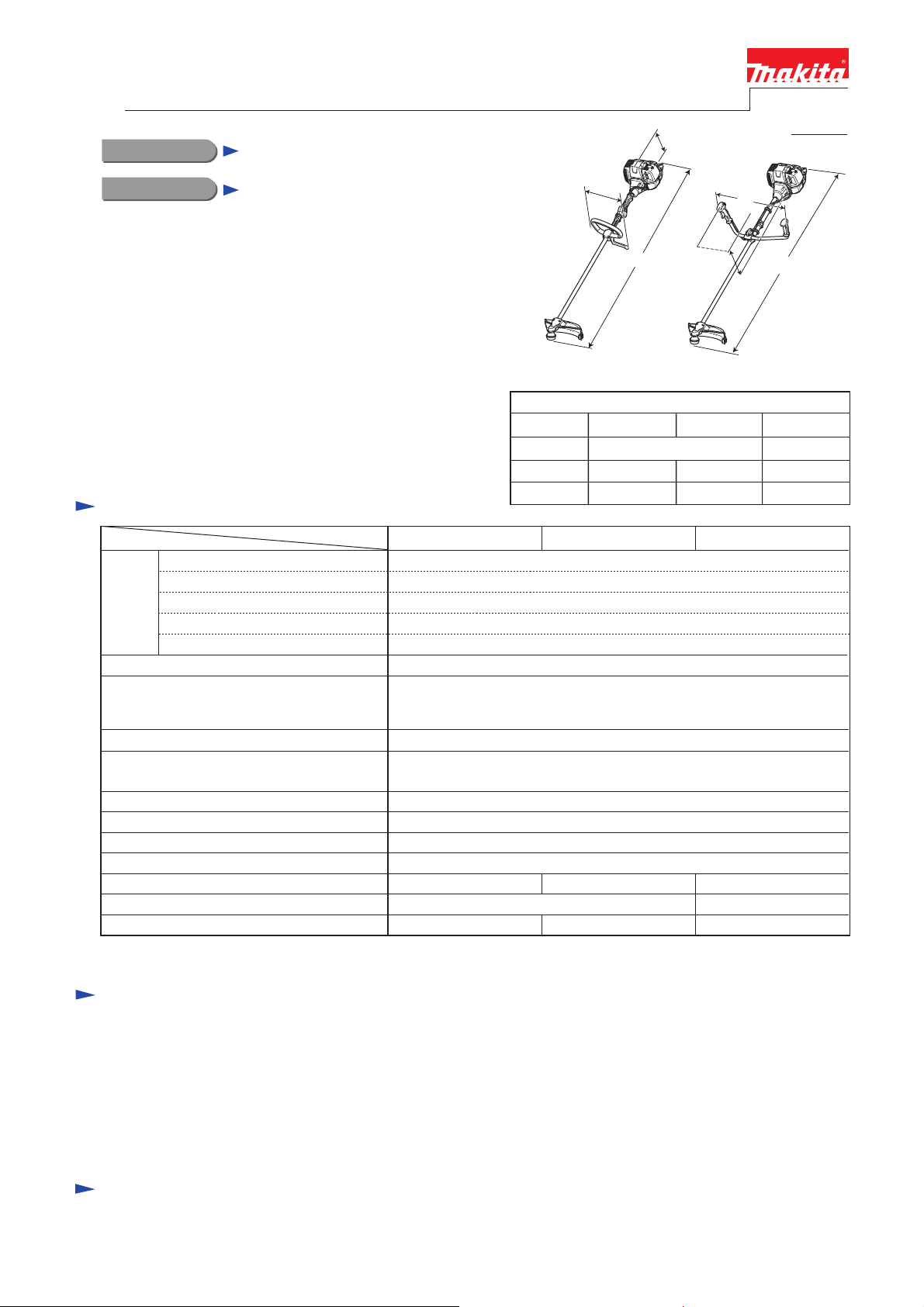
Specification
EM4350LH
Length (L)
Width (W)
Height (H)
PRODUCT
H
W
L
EM4350UH
EM4351UH
Dimensions: mm (")
EM4350UH EM4350LH EM4351UH
1,812 (71-1/2)
635 (25) 339 (13-3/8) 618 (24-1/4)
460 (18-1/8) 528 (20-3/4)250 (9-7/8)
W
H
P 1/ 2
L
The drawing
above is
EM4350UH.
1,812 (71-1/2)
2
Specifications
Type
Displacement: cm³ (cu.in.)
Engine
Max. spindle speed at no load: min.ˉ¹ = rpm
Engine oil
Carburetor
Engine start assist
Primer pump
Clutch
Anti-vibration system
Net weight*1: kg (lbs) 7.9 (17.3)
*1 Dry weight, without universal guard, cutting tool and shoulder harness
Fuel
Max. output: kW (PS)
Max. torque: N.m
Model
in the Class SF or higher of API Classification
(Automotive 4-stroke engine oil)
(by automatic mechanical decompression valve)
Bike handle
Conventional low-vibration structure
8.3 (18.2)
EM4350LH
4-stroke
43.0 (2.6)
Straight unleaded gasoline
1.50 (2.1) at 7,500 rpm
2.1 at 5,500 rpm
7,200
SAE10W-30 oil
Diaphragm
Yes
Yes
Yes
0.62 (21.0)Fuel tank capacity: L (US oz)
M10x1.25, Left-handedSpindle thread size
Loop handleHandle style
EM4351UHEM4350UH
Bike handle
Floating structure
8.6 (18.9)
Standard equipment
Blade or Nylon cutting head ..................... 1
Universal guard (=Protector) .................... 1
Blade cover ............................................... 1 (for the model with blade)
Double shoulder straps with waist pad ..... 1 (for EM4350UH)
Double shoulder straps with waist pad
for Loop handle model...... 1 (for EM4350LH)
Double shoulder straps with waist belt ..... 1 (for EM4351UH)
Note: The standard equipment for the tool shown above may vary by country.
Tool set (Hex wrench 4, Hex wrench 5,
Socket wrench 16-17,
Socket driver 16-10) .................. 1
Accessory bag ............................................ 1
Oil bottle without oil or
Oil bottle containing 100mL engine oil ..... 1
Optional accessories
255mm Triple blade, 300mmTriple blade, 255mm Star blade, 200mm Chisel blade, 225mm Chisel blade,
Nylon cutting heads (UltraAuto 6), Protector, Protector extension, Protector 200 set, Protector 225 set,
Double shoulder straps, Oil bottle
Page 2

P 2/ 22
Repair
CAUTION: Repair the machine in accordance with “Instruction manual” or “Safety instructions”.
[1] NECESSARY REPAIRING TOOLS
DescriptionCode No. Use for
---
---
---
1R219
Retaining ring pliers ST-2 for External ring1R004
Retaining ring pliers RT-2N for Internal ring1R005 removing/ installing Cotter by using 1R389
Retaining ring pliers RT-2E for Internal ring1R006 removing/ installing Retaining rings
Bearing setting pipe 20-12.21R028
Bearing setting pipe 28-20.21R031
Air density tester1R127 diagnosing Carburetor
Round bar for arbor 20-1001R247 removing Clutch drum complete from Clutch case
Round bar for arbor 8-501R282
Round bar for arbor 12-501R286 press-fitting Clutch drum complete into Clutch case
Retaining ring S and R pliers1R291 removing/ installing Retaining rings
Flywheel puller1R364 removing Flywheel
Feeler gauge set1R366 adjusting Ignition coil, Spark plug
Cotter removal attachment1R389 removing/ installing Cotter by using 1R005
10mm Hex socket bit
14mm Hex socket bit
Wire brush
Torque wrench shaft 7-23N.m
Torque wrench shaft 2-6N.m1R254
removing/ installing Retaining rings
press-fitting Cutter shaft set into Ball bearing 6000DDU
removing Spiral bevel gear 14 from Ball bearing 609ZZ
press-fitting Clutch drum into Ball bearing 6004LLU/6003LLU
removing Ball bearing 6000DDU from Cutter shaft completeBearing setting plate 10.21R033
removing Ball bearingsGear extractor (Large)1R045
removing Spiral bevel gear 14 from Ball bearing 6000ZZ and
6000
removing Piston pin
removing/ installing Flywheel
removing/ installing Clutch
cleaning Spark plug
tightening Bolts to specified torque
[2] HANDLING OF GASKET
Once Gasket is removed:
(1) Clean up the mating surface where the gasket was installed to maintain its sealing performance.
(2) Replace it with a new one.
[3] LUBRICANT / ADHESIVE APPLICATION
(1) Apply a little amount of Makita grease N No. 2 to Spiral spring in Recoil starter and the spline ends of Shaft in
Shaft pipe complete.
(2) When the inside of Gear case is cleaned, supply 11g of Makita grease N No. 2 from the grease inlet.
(3) Apply 4g of Makita grease N No. 1 to the entire portion of Shaft in Shaft pipe complete.
(4) Once Engine is disassembled, remove oil/grease from the mating surface of Cylinder and Crankcase complete,
then apply ThreeBond 1215/1216 to the mating surface for the reassembly.
[4] DISASSEMBLY/ASSEMBLY
[4]-1. Warning
Follow the instructions described below in advance before repairing:
• Wear gloves.
• Remove the cutting tool from the unit, and if it is a saw blade, attach the blade cover to the blade.
• When the engine is hot from use, cool down the engine enough or you can get burned.
• Remove remaining fuel from Fuel tank and Carburetor completely. [FLAMMABLE MATERIAL KEEP FIRE AWAY]
• Remove Spark plug cap from Spark plug.
• Repair the engine on a stable workbench and in a clean workplace kept as free of dust and debris as possible.
• In order to avoid wrong reassembly, draw or write down where and how the parts are assembled, and what are the parts.
It is also recommended to have boxes ready to keep disassembled parts by group.
• Handle the disassembled parts carefully. Clean and wash them properly.
• If some bolts and screws are too tight, use an impact driver.
• Tighten the bolts and the screws to the specified torque as shown in "[4]-15. Tightening torque specifications".
• Each time after you mounted a main part of the engine such as the piston, check if it moves smoothly
without abnormal noise by manually turning the crankshaft.
• After completion of reassembly, check for loose parts or abnormal noise and vibration
by manually turning the crankshaft.
Page 3
P 3/ 22
Repair
[4] DISASSEMBLY/ASSEMBLY
[4]-2. Engine and Shaft
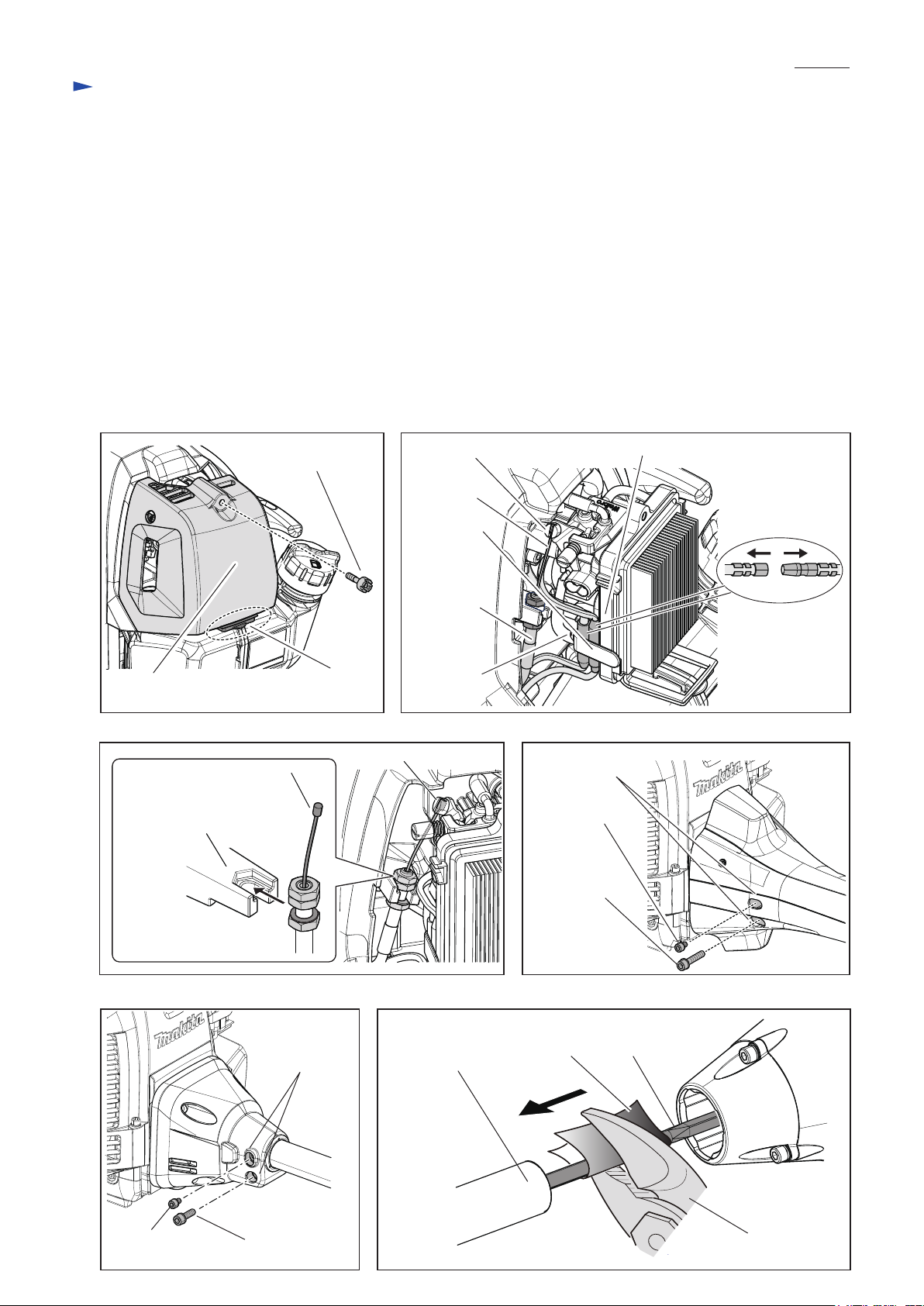
(1) Press down the tab of Cleaner plate assembly gently and separate Cleaner cover assembly from Cleaner plate assembly
by loosening M5x20 Hex socket head bolt. (Fig. 1)
(2) Loosen 5x16 Tapping screw and loosen Clamp that holds Bullet terminals near Cleaner plate assembly. (Fig. 2)
(3) Disconnect Bullet terminals of Earth wire and Primary wire of Ignition coil from the wires of Stop switch. (Fig. 2)
(4) Remove Control cable from Swivel of Carburetor; loosen the three nuts on Control cable to release the tension
between Swivel and Cable bracket of Insulator, then remove the stopper on Inner cable end from Swivel. (Fig. 3)
(5) For EM4351UH: Remove M5x8 Hex socket head bolt and M6x30 Hex socket head bolt in the holes of Pipe housing.
(Fig. 4)
For EM4350UH and EM4350LH: Remove M5x8 Hex socket head bolt and M6x30 Hex socket head bolt from
the threaded holes of Clutch case. (Fig. 5)
(6) Grab Shaft pipe complete by hand, then pull it off from Clutch case.
If Shaft sticks in Clutch case, use water pump pliers or the like to pull it off.
Note: Be sure to wrap Shaft with a rag or the like to protect it from water pump pliers. (Fig. 6)
Fig. 1
Fig. 2
M5x20 Hex socket
head bolt
Inner cable
Clamp
Control cable
Cleaner cover
assembly
Fig. 3 Fig. 4
Stopper on Inner cable end
Cable bracket of Insulator
Nut on Control cable end
(3 pcs.)
Cleaner plate assembly
Tab of
Swivel of Carburetor
5x16
Tapping
screw
Holes of
Pipe housing
M5x8
Hex socket
head bolt
M6x20
Hex socket
head bolt
Cleaner plate assemblySwivel of Carburetor
Bullet terminals
Fig. 5 Fig. 6
M5x8 Hex socket
head bolt
Threaded holes
of Clutch case
M6x20 Hex
socket head bolt
Shaft pipe complete
ShaftRag
Water pump
pliers
Page 4
P 4/ 22
Repair
[4] DISASSEMBLY/ASSEMBLY
[4]-2. Engine and Shaft (cont.)
ASSEMBLING
Assemble by reversing the disassembly procedure.
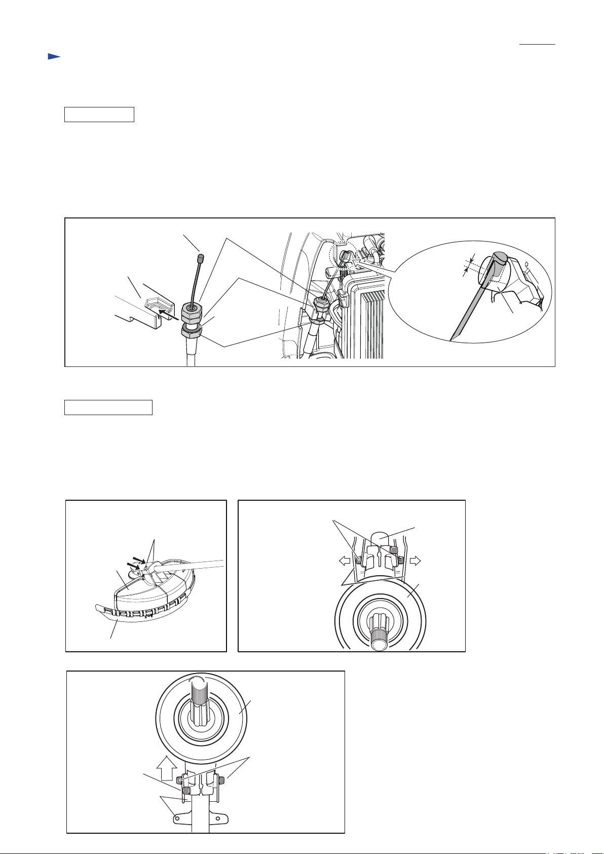
(1) Put Cable bracket between Flat washer 6 and middle Nut, and tighten them by turning lower nut, upper nut and
the middle nut. (Fig. 7)
(2) Put Stopper on Inner cable end into Swivel, then adjust the above nuts so that 3mm to 4mm of play is left inside of
Swivel under condition that Throttle lever is not pulled. (Fig. 7)
Note: Adjust the tension of Inner cable to prevent the stopper from being removed . (Fig. 7)
Fig. 7
Stopper on Inner cable end
Cable bracket of Insulator
complete
Nut (upper)
Nut (middle)
Flat washer 6
Nut (lower)
Play: 3mm to 4mm
Swivel
[4]-3. Shaft pipe complete
DISASSEMBLING
(1) Loosen two M6x30 Hex. socket head bolt (2pcs.) and remove Protector with Protector extension attached. (Fig. 8)
(2) Enlarge the space between the side wall of Protector cover and M5x14 Hex socket head bolt, and remove Protector cover
from Shaft pipe complete. (Fig. 9)
(3) Remove two M5x14 Hex socket head bolts then remove Protector clamp.
(4) Loosen M6x30 Hex socket head bolt then remove Gear case assembly. (Fig. 10)
Fig. 8
M6x30 Hex. socket
head bolt (2 pcs.)
Fig. 9
M5x14 Hex socket head bolt (2 pcs.)
Shaft pipe
complete
Protector
Protector extension
Fig. 10
M6x30 Hex
socket head bolt
Protector clamp
The side wall of
Protector cover
Gear case assembly
M5x14 Hex socket
head bolt (2 pcs.)
Gear case
assembly
Page 5
P 5/ 22
Repair
[4] DISASSEMBLY/ASSEMBLY
[4]-3. Shaft pipe complete (cont.)
DISASSEMBLING
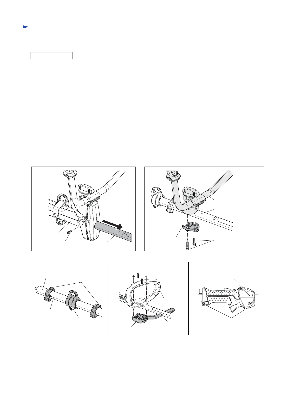
For 4351UH:
(5A) Loosen M5x18 Hex socket head bolt and remove Shaft pipe complete from Pipe housing. (Fig. 11)
(6A) Pull out Shaft from Shaft pipe complete.
For 4350UH:
(5B) Remove two M6x25 Hex socket head bolts and Pipe clamp, then separate Bike handle section from Shaft pipe
complete. (Fig. 12)
(6B) Remove the following parts from Shaft pipe complete.
• Wire clamp (2 pcs.) • Hanger set • Shaft (Fig. 13)
For 4350LH:
(5C) Remove four M5x30 Hex socket head screws, then remove Handle clamp 28 and then remove Loop handle 28.
(Fig. 14)
(6C) Loosen two M5x14 Hex socket head bolts, then separate Lever case set from Pipe shaft complete. (Fig. 15)
(7C) Remove the following parts from Pipe shaft complete.
• Hanger set • Spacer • Shaft
Fig. 11
Pipe housing
M5x18 Hex socket head bolt
Fig. 13 Fig. 14 Fig. 15
Shaft
Wire clamp (2 pcs.)
Shaft pipe
Fig. 12
Pipe clamp
M5x30 Hex socket
head screw (4 pcs.)
Loop handle 28
Bike handle section
Shaft pipe complete
M6x25 Hex
socket head bolt
Control lever assembly
Shaft pipe
complete
Hanger set
Handle clamp 28
Shaft pipe
complete
M5x14 Hex socket
head bolt (2 pcs.)
Page 6
Repair
[4] DISASSEMBLY/ASSEMBLY
[4]-3. Shaft pipe complete (cont.)
ASSEMBLING
For 4351UH:
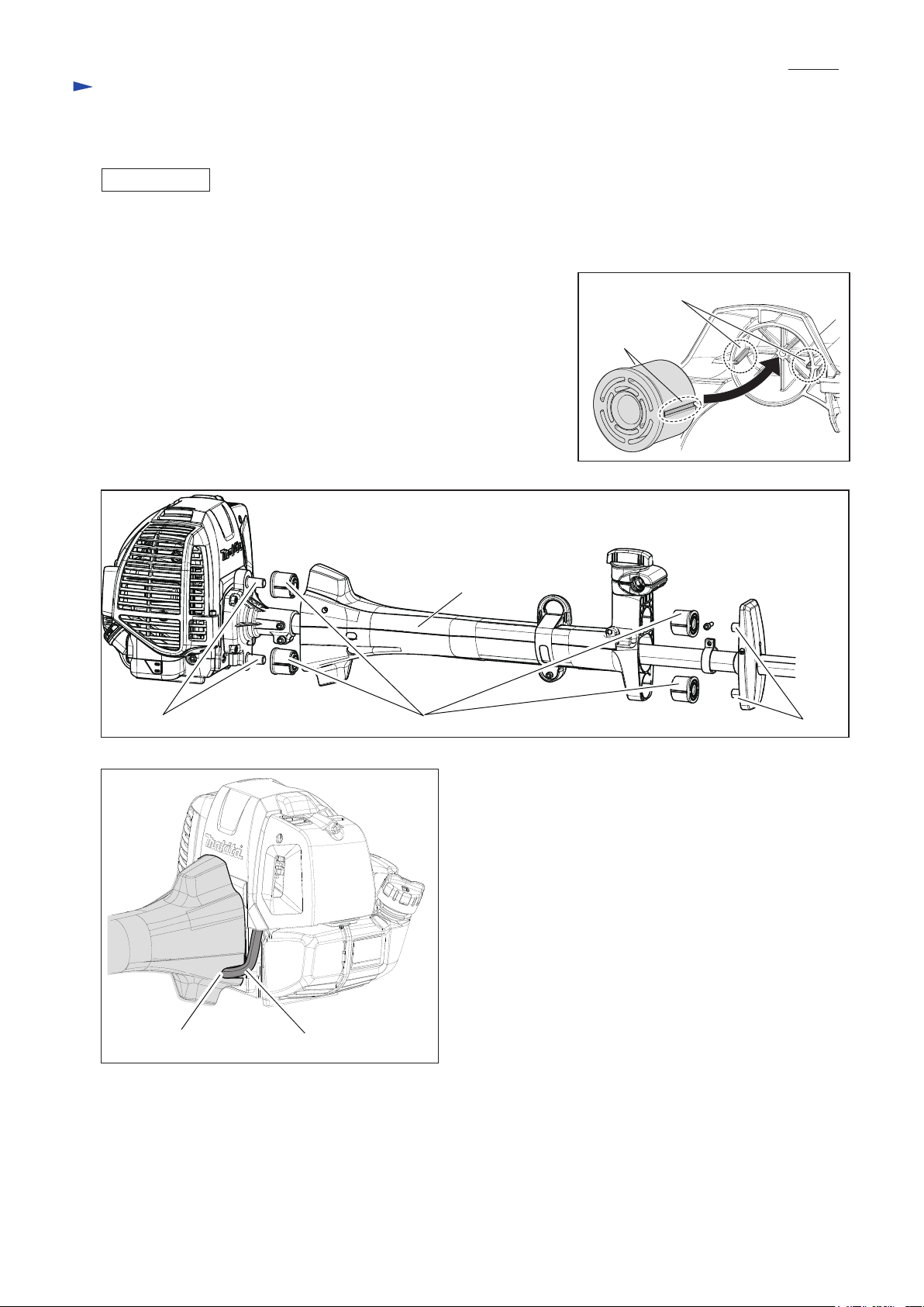
(1A) Insert Buffer rubber into Pipe housing so as to align the two grooves
with the two ribs (Fig. 16) Set the four Buffer rubbers in place of
Pipe housing. (Fig. 17)
(2A) Insert two projections of Clutch case into Buffer rubbers.
Insert two projections of Housing holder into the other Buffer rubbers,
then tighten M5x18 Hex socket head bolt while holding Housing
holder by hand. (Fig. 17)
Note: Make sure that Corrugate tube is put in the groove of Pipe housing.
(Fig. 18)
(3A) Assemble by reversing the disassembly procedure.
For 4350UH and 4350LH:
Assemble by reversing the disassembly procedure.
Fig. 17
P 6/ 22
Fig. 16
Ribs of Pipe housing
Grooves of
Buffer rubber
Projections of Clutch case
Fig. 18
Pipe housing
Buffer rubber (4 pcs.) Housing holder
Groove of Pipe housing
Corrugate tube
Page 7
P 7/ 22
Repair
[4] DISASSEMBLY/ASSEMBLY
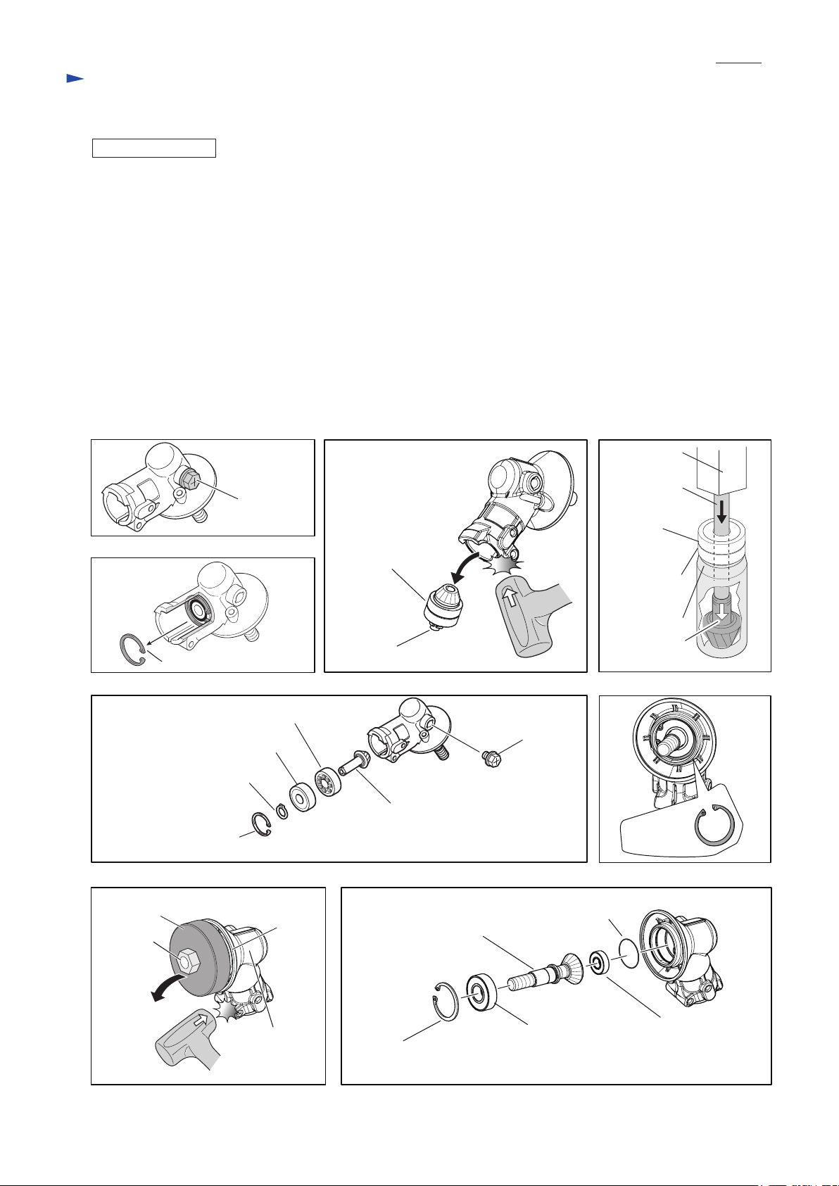
[4]-4. Gear case assembly
DISASSEMBLING
(1) According to the clause of [4]-3, Remove Gear case assembly. (Refer to Figs. 8, 9 and 10)
(2) Remove M8x10 + Hex bolt from the grease inlet of Gear case assembly. (Fig. 19)
(3) Remove Retaining ring R-26 with 1R006. (Fig. 20)
(4) Remove an assembled part of Spiral bevel gear 13*, Ball bearing 6000ZZ, Ball bearing 6000 and Retaining ring S-10
by tapping Gear case assembly with Plastic hammer. (Fig. 21)
Note: If the assembled part cannot be removed, use a heat gun or hair dryer to warm Gear case assembly.
(5) Remove Retaining ring S-10 with 1R291. (Fig. 21)
(6) Receive Ball bearing 6000 with 1R031, then press down the shaft end of Spiral bevel gear 13 using 1R282 with
Arbor press. (Fig. 22) Refer to Fig. 23 for the components.
(7) Remove Retaining ring R-32 with 1R291. (Fig. 24)
(8) Preset Receive washer and 1R033 with M10-17 Hex nut to Cutter shaft complete* as drawn in Fig. 25, and give
the impacts using the plastic hammer. An assembled part of Cutter shaft complete* and Ball bearing 6201LLU is
removed. Refer to Fig. 26 for the components.
(9) Remove Ball bearing 6201LLU with 1R045.
*Neither Spiral bevel gear 13 or Cutter shaft set is supplied individually. It is supplied as a set “Cutter shaft set”.
Fig. 19
Fig. 21 Fig. 22
Arbor press
M8x10
+ Hex bolt
Fig. 20
Retaining ring R-26
Fig. 23
Ball bearing 6000
Ball bearing 6000ZZ
Retaining ring S-10
Retaining ring R-26
It was removed by the previous step (3).
Fig. 25 Fig. 26
Assembled part
Retaining ring S-10
1R282
Ball bearing
6000ZZ
Ball bearing
6000
1R031
Spiral bevel
gear 13*
Fig. 24
M8x10
+ Hex bolt
Spiral bevel gear 13*
Retaining
ring R-32
M10-17
Hex nut
1R033
Receive
washer
Gear case
assembly
Cutter shaft complete*
Ball bearing 6201LLU
Retaining ring R-32
It was removed by the previous step (7).
O ring 32
Ball bearing 629ZZ
Page 8

Repair
P 8/ 22
[4] DISASSEMBLY/ASSEMBLY
Fig. 27
[4]-4. Gear case assembly (cont.)
ASSEMBLING
Assemble by reversing the disassembly procedure.
Note:
• Make sure that O ring 32 is put into the inner groove of
Gear case assembly in advance.
• When mounting Cutter shaft complete into Gear case
assembly, press-fit them together using arbor press and
1R028 as shown in Fig. 27.
The components of
Cutter shaft complete
Gear case assembly
1R028
Ball bearing
6000DDU
[4]-5. Clutch shoe
DISASSEMBLING
Warning: Remove Spark plug cap from Spark plug to prevent accidental engine starting.
Note: Clutch can be easily removed with a cordless impact driver without locking Piston, because it is locked in a position
due to the compressed air resistance in Cylinder.
Therefore, do not remove Spark plug, or the air in Cylinder cannot be compressed.
(1) Remove two Clutch shoes and Tension springs 5 by loosening each M8 Shoulder hex bolt counterclockwise. (Fig. 28)
(2) Remove Clutch base by turning the hex portion counterclockwise. (Fig. 29)
Fig. 28 Fig. 29
Clutch shoe (2 pcs.)
Hex portion of
Clutch base
M8 Shoulder hex bolt
(2 pcs.)
Tension spring 5 (2 pcs.)
ASSEMBLING
(1) Set Clutch base in place by turning the hex portion clockwise.
(2) Set two Clutch shoes and Tension springs 5 in place by tightening each M8 Shoulder hex bolt clockwise; first by hand,
then with a cordless impact driver*
*This is because the M8 Shoulder hex bolt is a shoulder bolt. Therefore, tighten by hand until the shoulder of the shaft portion contacts the upper end
surface of Clutch shoe, then tighten fully with a cordless impact driver. (Fig. 30)
Note:
• Face the arrow marks on Clutch shoes toward the upper side. (Fig. 31)
• Put Clutch shoe between Wave washer 10 and Flat washer 8, then tighten M8 Shoulder hex bolt.
Refer to Figs. 30 and 31.
Fig. 30 Fig. 31
M8 Shoulder hex bolt
Wave washer 10
shaft portion
shoulder
Clutch shoe
Flat washer 8
Clutch base
Clutch base
Flat washer 8
(2 pcs.)
Wave washer 10 (2 pcs.)
M8 Shoulder hex bolt (2 pcs.)
Arrow marks on
Clutch shoes
(2 pcs.)
Page 9

Repair
[4] DISASSEMBLY/ASSEMBLY
[4]-6. Clutch drum
DISASSEMBLING
For 4351UH: Refer to Parts breakdown in Fig. 35.
(1A) Remove four M6x20 Hex socket head bolts, then separate Clutch case from Engine. (Fig. 33)
(2A) Remove Retaining ring (INT) R-42 in Clutch case with 1R006. (Fig. 33)
(3A) Put 1R247 on Clutch drum in Clutch case, press down Clutch drum using Arbor press. (Fig. 34)
Note: If it is difficult to remove Clutch drum from Clutch case, warm Clutch case with a heat gun.
(4A) Remove Retaining ring (EXT) WR-20 from Clutch drum with 1R004.
(5A) Remove Ball bearing 6004LLU from Clutch drum with 1R045.
Fig. 35Fig. 34Fig. 32
Engine
Clutch case
M6x20 Hex
socket head screw
(4 pcs.)
Fig. 33
Arbor
press
1R247
Clutch
case
P 9/ 22
Clutch case
Retaining ring
(EXT) WR-20
Inside view of
Clutch case
For 4350UH and 4350LH: Refer to Parts breakdown in Fig. 39.
(1B) Remove four M6x20 Hex socket head bolts, then separate Clutch case from Engine. (Fig. 36)
(2B) Remove three M5x20 Hex socket head bolts, then separate Pipe retainer from Clutch case. (Fig. 36)
(3B) Remove Retaining ring R-35 in Clutch case with 1R006. (Fig. 37)
(3B) Put 1R247 on Clutch drum in Clutch case, press down Clutch drum using Arbor press. (Fig. 38)
Note: If it is difficult to remove Clutch drum from Clutch case, warm Clutch case with a heat gun.
(4B) Remove Retaining ring S-17 from Clutch drum with 1R004.
(5B) Remove Ball bearing 6003LLU from Clutch drum with 1R045.
M6x20 Hex socket head
screw (4 pcs.)
M5x20 Hex
socket head
screw (3 pcs.)
Clutch drum
Holes for
access to
Retaining ring
(INT) WR-42
Clutch case
Clutch drum
Arbor
press
1R247
Ball bearing
6004LLU
Retaining ring
(INT) WR-42
Clutch drum
Fig. 39Fig. 38Fig. 36
Clutch
case
Clutch case
Fig. 37
Inside view of
Clutch case
Holes for
access to
Retaining ring R-35
Pipe retainer Clutch case
Clutch drum
Clutch case
Spacer
Retaining ring
S-17
Ball bearing
6003LLU
Clutch drum
Retaining ring
R-35
Clutch drum
Page 10

P 10/ 22
Repair
[4] DISASSEMBLY/ASSEMBLY
[4]-6. Clutch drum (cont.)
ASSEMBLING
For 4351UH:
(1) Press-fit Ball bearing 6004LLU to Clutch drum with 1R031 in Fig. 40.
Note: Put Retaining ring (INT) R-42 between Ball bearing 6004LLU and Clutch drum in advance.
(2) Set Retaining ring (EXT) WR-20 in the groove on Clutch drum.
(3) Put Clutch case on the table of Arbor press horizontally without tilt, and press-fit Clutch drum into Clutch case with
1R286. (Fig. 41)
(4) Set Retaining ring (INT) R-42 to the inner groove of Clutch case.
(5) Assemble by reversing the disassembly procedure.
Fig. 40
Arbor press
Clutch drum
Fig. 41
1R286
Retaining ring (INT)
R-42
Ball bearing 6004LLU
1R031
For 4350LH and 4350UH:
(1) Press-fit Ball bearing 6003LLU to Clutch drum with 1R031 in Fig. 42.
Note: Put Retaining ring R-35 between Ball bearing 6003LLU and Clutch drum in advance.
(2) Set Retaining ring S-17 in the groove on Clutch drum.
(3) Put Clutch case on the table of Arbor press horizontally without tilt, and press-fit Spacer and Clutch drum into
Clutch case with 1R286. (Fig. 43)
(4) Set Retaining ring R-35 to the inner groove of Clutch case.
(5) Assemble by reversing the disassembly procedure.
Arbor press
Clutch drum
Clutch case
Fig. 43Fig. 42
1R286
Retaining ring R-35
Ball bearing 6003LLU
1R031
Clutch case
Spacer
(Refer to Fig. 39 of
the previous page.)
Page 11

P 11/ 22
Repair
[4] DISASSEMBLY/ASSEMBLY
[4]-7. Ignition system
CHECKING PLUG CAP
(1) Remove Plug cap from Spark plug, then check the continuity between Plug cap spring and the ground (earth) terminal
of Ignition coil with a circuit tester. If there is normal continuity, the resistance value will be 2.0kΩ±0.5kΩ. (Fig. 44)
(2) If there is no or intermittent continuity, check the continuity between Ignition cable and Plug cap spring by following
the procedure described below.
1. Apply spray lubricant in Plug cap, then pull out Plug cap spring together with Ignition cable from Plug cap using
small pliers. (Fig. 45)
2. Check if Plug cap spring is properly connected to Ignition cable. If not, connect them properly.
Also check Plug cap for any crack. If Plug cap is cracked, replace it with a new one.
3. Insert Plug cap spring in the center of Ignition cable. Then using small pliers, put them back into Plug cap while
taking care not to disconnect Plug cap spring from Ignition cable.
4. Make sure that Plug cap spring is firmly connected to Ignition cable by doing the same as you did in step (1) with
a circuit tester.
Note: Poor continuity between Plug spring cap and Ignition cable will result in no or weak spark.
Fig. 44
Plug cap
Plug cap spring
Fig. 45
Small pliers
Plug cap spring
Ignition coil
Circuit tester
Primary wire of
Ignition coil
CHECKING SPARK PLUG
WARNING !!
• When a spark is produced, high-voltage current is delivered from Ignition coil to Spark plug.
It is, therefore, very dangerous to pull Recoil starter knob with your hand on Ignition cable.
Be sure to keep your hands off from Ignition cable when checking for spark.
• Fuel is extremely flammable and fuel vapors are explosive.
Therefore, clean up spilled fuel before starting to check for spark.
Also, be careful not to do the check near Carburetor.
(1) Remove Plug cap from Spark plug, then Spark plug from Cylinder with the supplied socket wrench.
Note: If the electrodes of Spark plug are wet, wipe them with a rag then dry them with an air blower.
(2) Using a wire brush, carefully clean up carbon deposits (if any) from the electrodes and the ceramic insulator
around the center electrode.
(3) Adjust the electrode gap to 0.7 to 0.8mm by carefully bending the side electrode.
Use Feeler gauge set (1R366) to check the gap width:
between the center electrode and the side electrode, insert 0.8mm leaf
of Feeler gauge set. (Fig. 45)
(4) Install another Spark plug into spark plug hole to prevent air/fuel
mixture from leaking outside of engine.
(5) Connect the removed Spark plug with Plug cap, then ground the threads
of Spark plug to a proper metal part of the engine.
(6) With Stop switch on, pull Recoil starter knob gently and check for spark.
Note: • It is hard to see the spark in a bright location. Therefore, be sure to
do the check in a shady but well-ventilated place.
• Sparks do not happen at without exceeding 500 rpm.
(7) If spark is not produced, replace Spark plug with a new one,
then check for spark by following the procedure (1) to (6) once again.
Fig. 46
side electrode
Electrode gap
must be
0.7 to 0.8mm.
center electrode
Page 12

Repair
[4] DISASSEMBLY/ASSEMBLY
[4]-7. Ignition system (cont.)
REMOVING IGNITION COIL
(1) Before removing Ignition coil, separate Cylinder cover
from Engine, and pull out Primary wire from Ignition coil
in advance. (Fig. 47)
(2) Remove two M4x20 Hex socket head bolts and Ignition coil
from Engine. (Fig. 47)
Note: Be careful to the torque to loosen the bolts because
adhesive is applied on the threads under our quality
control.
Once removing their bolts, do not fail to apply adhesive
to the threads.
Fig. 47
Female terminal of
Primary wire
P 12/ 22
M4x20 Hex socket
head bolt (2 pcs.)
Ignition coil
Spacer (2 pcs.)
MOUNTING IGNITION COIL
(1) Insert 0.3mm leaf of 1R366 between Ignition coil and
the magnet of Flywheel. (Fig. 48)
Ignition coil will be attracted to the magnet through 1R366.
Then, without removing 1R366, fasten Ignition coil to
Engine with two M4x20 Socket head bolts. (Fig. 47)
(2) Remove 1R366. Then make sure that Flywheel does not
touch Ignition coil by turning it by hand.
Fig. 48
[4]-8. Flywheel
Warning: Remove Spark plug cap from Spark plug to prevent accidental
engine starting.
Note: Flywheel can be easily removed with a cordless impact driver without
using any locking tool, because Piston is locked in a position due to
the compressed air resistance in Cylinder.
Therefore, do not remove Spark plug, or the air in Cylinder cannot be
compressed.
DISASSEMBLING
(1) Turn M8 Collared Hex nut in the center of Flywheel counterclockwise
using a cordless impact driver. (Fig. 49)
(2) Mount 1R364 on Flywheel, then screw two M5 bolts of 1R364 into
Flywheel as drawn in Fig. 50.
Flywheel can now be removed from Crankshaft complete by turning
the center bolt of 1R364 clockwise using a screwdriver or the like.
Important: Screw two M5 bolts evenly.
Ignition coil
0.3mm thick leaf
of 1R366
Flywheel
Fig. 49
M8 Collared
Hex nut
Fig. 50
ASSEMBLING
(1) Wipe off grease and oil from Crankshaft complete.
(2) Aligning the key way of Crankshaft complete with Woodruff key 3 on
Flywheel, install Flywheel onto Crankshaft complete. (Fig. 51)
(3) Screw M8 Collared Hex nut to Crankshaft complete by turning it clockwise
by hand.
(4) Tighten M8 Collared Hex nut firmly using an impact driver.
1R364
M5 bolt
of 1R364
(2 pcs.)
Fig. 51
Keyway in
the hole of
Flywheel
Woodruff key 3 on
Crankshaft complete
Page 13

Repair
[4] DISASSEMBLY/ASSEMBLY
[4]-9. Recoil starter
DISASSEMBLING
(1) Remove Starter cover assembly by loosening
four M5x20 Hex socket head bolts. (Fig. 52)
(2) Pull Starter rope out of Starter cover assembly
approximately one winding long.
Then hook Starter rope on the U-shaped notch of
Reel, and then turn Reel clockwise until Spiral
spring is unwound. (Fig. 53)
Note: Be careful with Reel because it will turn very
fast.
(3) Remove Reel from Starter cover by loosening
5x10 Tapping screw.
Note: Be careful with Spiral spring that can suddenly
pop out of Starter cover.
(4) Unite the knot of Starter rope to remove the rope
from Reel.
ASSEMBLING
Fig. 52 Fig. 53
Starter cover assembly
M5x20 Hex socket
head bolt
(4 pcs.)
Reverse side of
Starter cover assembly
U-shaped
notch of Reel
P 13/ 22
Starter rope
(1) If Spiral spring has popped out of Reel, put it back in place; hook the outer end of Spiral spring onto the spring hook
of Reel first, then by winding Spiral spring counterclockwise towards the center of Reel. (Fig. 54)
(2) Apply a little amount of Makita grease N No.2 to the whole surface of Spiral spring.
(3) Put a new Starter rope through Starter cover.
Then tie one end to Starter knob and the other to Reel by making
a knot. (Fig. 55)
(4) Make sure that the inner end of Spiral spring is positioned close to
the shaft portion of Starter cover for the step (6). Then put Reel in
Starter cover.
(5) Wind Starter rope around Reel two or three times.
(6) While turning Reel counterclockwise, mount it in Starter cover.
The inner end of Spiral spring will be engaged with the spring hook
of Shaft portion in Starter cover by the counterclockwise rotation of
Reel. (Figs. 54 and 55)
Note: You do not need force to mount Reel in place.
(7) Fasten Reel to the shaft portion of Starter cover with
M6x20 Set screw. (Fig. 56)
Note: Reel is not properly set in place if the rotation of
Reel is slow after the screw is fastened.
In this case, repeat steps (5) and (6) until normal
rotation of Reel is obtained.
(7) Hook Starter rope on the U-shaped notch of Reel.
Then, while pulling Starter rope, turn Reel counter clockwise. (Fig. 57)
Release Starter rope from the U-shaped notch and
Starter rope will be wound around Reel due to the
rotational force of Spiral spring. Repeat this operation
until the slack is completely removed from Starter rope.
Fig. 56 Fig. 57
Reel
M6x20 Set screw
Fig. 55
Spring hook of Shaft portion
in Starter cover
Starter rope
Fig. 54
Reel viewed from Starter cover side
Reel
Inner end of
Spiral spring
Outer end of
Spiral spring
Spring hook
of Reel
Starter rope
about
10mm
about
10mm
Starter cover
Starter rope
U-shaped notch of Reel
Page 14

Repair
[4] DISASSEMBLY/ASSEMBLY
[4]-10. Carburetor section
P 14/ 22
DISASSEMBLING
(1) Press down the tab of Cleaner plate assembly gently and separate
Air cleaner cover from Cleaner plate assembly by loosening
M5x20 Hex socket button head screw. (Fig. 1 of [4]-2.)
(2) Remove Air cleaner element. (Fig. 58)
(3) Remove two M5x60 Hex socket head bolts that fasten
Carburetor assembly and Cleaner plate assembly to Insulator
complete. (Fig. 59)
Note: Remove the bolts completely, or Carburetor cannot be
removed from Insulator complete.
(4) Remove three tubes from Carburetor assembly, then separate
Carburetor assembly from Engine.
DISASSEMBLING/ CLEANING CARBURETOR
(1) Remove four Pan head screws, then separate Metering cover, Metering diaphragm and Metering diaphragm gasket
from Carburetor. (Fig. 60)
Note: If Metering diaphragm gasket is sticking on the adjacent part, remove it with care because it is easily broken.
(2) Check Metering diaphragm for shrinkage, hardening or breakage due to aged deterioration. If any, replace it with
a new one.
(3) The inner parts of Pump body assembly can be removed by separating the pan head screw designated in Fig. 61.
(4) Before mounting the inner parts of Pump body assembly in place, make sure that the tip of Inlet needle is neither
worn nor deformed. (Fig. 62)
Note: The inner parts are not available individually. If you need any of the inner parts, order Pump body assembly.
(5) When mounting Control lever, make sure that the upper end of Spring is firmly held in place under the projection of
Control lever. (Fig. 63)
(6) Remove the pan head screw of Pump cover. (Fig. 64)
(7) Make sure that Inlet screen is not clogged, then set it back in place. (Fig. 65)
(8) Spray Carburetor cleaner in all the fuel lines of Carburetor, then after several minutes, wash out dirt and debris with
clean gasoline.
Fig. 60 Fig. 61
Fig. 58 Fig. 59
Air cleaner element M5x60 Hex socket
head bolt (2 pcs.)
Pan head screw (4 pcs.)
Carburetor
Fig. 62
with good tip with worn tip
An Inlet needle with
worn tip can cause
a pressure leak.
Fig. 64
Pan head screwPump cover
Inner parts of Pump body assembly
Pan head screw Pin
Inlet needle
Control lever
Fig. 63
Correct assembling
of the inner parts of
Pump body assembly
Metering diaphragm
Control lever
Spring
Inlet needle
Fig. 65
Inlet screen
Spring
Pump body assembly
Wrong examples
Debris in valve seat can
cause a pressure leak.
Control lever is not parallel
to Pump body assembly.
The upper end of Spring
is out of place.
Carburetor body
Page 15

P 15/ 22
Repair
[4] DISASSEMBLY/ASSEMBLY
[4]-10. Carburetor section (cont.)
ASSEMBLING CARBURETOR
Assemble by reversing the disassembly procedure.
Note: Make sure that the assembling direction of each part is correct.
VACUUM LEAK TEST OF CARBURETOR
Connect 1R127 with the fuel inlet of Carburetor, then increase the testing
pressure up to 0.05Mpa. The pressure will stay the same about 10 seconds
if there is no vacuum leak. (Fig. 66)
MOUNTING CARBURETOR
(1) Fasten the following parts to Cylinder block assembly with two M5x60 Pan head screws. (Fig. 67)
Carburetor gasket (2 pcs: small and large) , Carburetor, Cleaner plate assembly, Insulator complete
(2) Connect three Tubes to Carburetor as drawn in Fig. 68.
Then connect Tube 5-160 and Pipe to Cleaner plate assembly as drawn in Fig. 69.
(3) Mount Air cleaner element onto Cleaner plate assembly.
(4) Mount Air cleaner cover complete onto Air cleaner plate, then secure with M5x20 Hex socket head bolt. (Fig. 1 of [4]-2.)
Note: Be sure to fit the tab of Cleaner plate assembly into the slot of Cleaner cover assembly.
Fig. 67
Carburetor
Carburetor
gasket (small)
Carburetor gasket (large)
behind Carburetor
Fig. 68
Tube 3-120 (blue)
between Primer pump
and Carburetor
Tube 3-35 between Carburetor
and Insulator complete
Fig. 66
Carburetor
1R127
Tube 3-250 (black)*
between Carburetor
and Fuel tank
*The component of
Tube complete
Cleaner plate
assembly
M5x70 Pan head
screw (2 pcs.)
Fig. 69
Tube 5-160 and Pipe are connected as follows:
Cylinder
block
assembly
Rocker cover outer
Carburetor
gasket (large)
Carburetor
gasket (small)
Primer pump
Fuel tank
CarburetorInsulator complete
Clamp on Insulator completeClamp on
Tube 5-160 (black) for Rocker cover outer
and Cleaner plate assembly
(Corrugate tube)
(Spiral tube 6-100 to
protect Tube 3-120)
Cleaner plate assembly
Tube 5-160
(black)
Cleaner plate
assembly
Pipe
Pipe for Cleaner plate assembly and the nipple of Cylinder block assembly
Page 16

Repair
[4] DISASSEMBLY/ ASSEMBLY
[4]-11.
Stop switch section
P 16/ 22
CHECKING STOP SWITCH
Check the continuity between the bullet terminals on the two lead wires
extending from Control lever with a circuit tester. (Fig. 70)
If Stop switch functions properly, there will be no continuity with
the switch ON and there will be continuity with the switch OFF.
Fig. 70
[4]-12. Fuel tube section
FUEL TUBE ROUTING
Set Tube complete* in place as shown in Fig. 71.
• Connect Tube 3-260 to Carburetor and Gasoline filter with Hose clamp.
• Connect Tube 3-150 to the long pipe of Primer pump.
• Connect Tube 3-120 to the short pipe of Primer pump.
Also refer to Fig. 72.
(3) Put Coil spring 8 and Clamp on Tube 3-150. (Fig. 71)
(4) Route Tube 3-150 as drawn in Fig. 72.
Route Tube 3-120 between Tube 3-150 and Cleaner plate assembly. (Fig. 73)
Fig. 71
Holders of
Cleaner plate assembly
Tube 3-260 (black)
Breather (to intake air into Tank)
Gasoline filter
(to Carburetor)
Hose clamp
Tube 3-260
(black)
Tube complete
Breather
long pipe of
Primer pump
Clamp
Coil
spring 8
Tube 3-150 (blue)
Fuel tank
Fig. 72 Fig. 73
Nipple of Carburetor
Tube 3-120
(blue)
Spiral tube
6-100
(to intake air into Tank)
Tube 3-260
(black)
Tube 3-150
(blue)
Fuel tank
Tube
3-150
(blue)
Tube 3-120
(blue)
Grommet
short pipe of Primer pump
to connect Tube 3-120
(Refer to Figs. 68 and 69.)
Tube 3-150 (blue)
Spiral tube 6-80
Pipe
Breather
Page 17

P 17/ 22
Repair
[4] DISASSEMBLY/ASSEMBLY
[4]-13. Engine block
DISASSEMBLING
(1) It is highly recommended to drain the oil system of Engine block before starting disassembling
because the oil remaining there will drip out to delay your operation.
(2) From the engine section, remove the following parts):
Ignition coil, Flywheel complete, Rocker cover inner, Rocker cover outer, Rocker arm assembly (2 pcs),
Rod 2.5 (2 pcs), Cam lifter (2 pcs), Cam gear assembly, Insulator complete, Cleaner plate assembly, Carburetor,
Spark plug, Exhaust muffler.
(3) Remove the assembly of Cylinder head and Cylinder block. (Fig. 74)
(4) Remove Clip (2 pcs. in total) from each end of Piston pin with a pointed tool such as an awl as shown in Fig. 75.
Note: • Be careful with Clip because it can pop out unexpectedly during removal operation.
• Do not use removed Clip. Be sure to replace it with new one.
(5) Remove Piston pin with 1R171 or the like as shown in Fig. 76.
(6) Remove Piston from Crankshaft complete, then separate Top ring, Second ring and Oil ring from Piston.
Note: Mark on one of Top or Second ring to distinguish the original position for reassembling.
Fig. 74
Cylinder head
Cylinder block
Crank case
Piston
Crank shaft
complete
Fig. 75
Fig. 76
Piston pin
Awl
Piston
Clip
1R171
Page 18

P 18/ 22
Repair
[4] DISASSEMBLY/ASSEMBLY
[4]-13. Engine block (cont.)
ASSEMBLING
(1) Connect Piston with Crank shaft complete by inserting Piston pin into place; there is no front/back to Piston.
Note: Be sure to apply a little amount of Makita grease N No.2 to Needle roller bearing.
(2) Secure Piston pin by mounting Clip onto each end of Piston pin. Any setting direction is allowed.
(3) Install Oil ring in the grooves of Piston; Side rail first, Spacer next, then the other Side rail.
Important: Be sure to fit the three rings with the ring gaps at 120 degrees to one another as shown in the left of Fig. 77.
(4) Install Second ring first then Top ring in the groove of Piston.
Important 1: Be sure to fit the two rings with the ring gaps at 180 degrees to each other as shown in the right of Fig. 77.
Important 2: Second ring has a taper face and must be installed with the large diameter facing Oil ring. (Fig. 78)
Distinguishing between Top ring and Second ring & Discriminating the larger diameter of Second ring:
If both of the two rings are new and unused,
• You can distinguish from their appearances; there is a T marking on the right upper end of Second ring as shown in
Fig. 75 while not on the upper end of Top ring.
• You can face the large diameter of Second ring by placing Second ring with the T marking on your right and
with the ring gap near you as shown in Fig. 79.
If both of the two rings are used and the T marking of Second ring is rubbed off, carefully press the side face of
the two rings to the inner wall surface of Cylinder. You will be able to distinguish the two rings or to discriminate
the large diameter of Second ring through the differences in contact feelings that the different side faces make.
Fig. 77
Oil ring
ring gap
Side rail
Spacer
Side rail
ring gap
ring gap
Fig. 78 Fig. 79
Second ring
Top ring, with barrel face
Second ring, with taper face
Side rail
Spacer Oil ring
Side rail
ring gap
Top ring
Second ring
ring gap
Note: Makita genuine second ring
has T marking on the right
upper end if it is not worn out.
Face the T marking toward
upward for assembly.
T
T marking
(5) Apply 4-cycle engine oil to the following portions:
Oil ring, Needle roller bearing that holds Piston pin,
Needle roller bearing of Crank shaft complete.
(6) Remove oil/grease from the mating surface of
Cylinder block and Crank case.
Then apply ThreeBond 1215/ 1216 carefully to
the mating surface of Crank case as shown in Fig. 80.
Note: Do not apply the adhesive to the area
designated by the enlarged view.
Apply 4-cycle engine oil to the sliding surface of
Piston section and Cylinder block assembly, and then
while compressing Piston rings, mount Cylinder block
onto Crank case.
(7) Tighten eight M6x25 Hex socket head bolts in
a crisscross pattern.
Fig. 80
Crank case viewed
from the upper side
Gray colored portions:
where the adhesive should
be applied
Do not apply the adhesive
to the designated area.
Page 19

Repair
[4] DISASSEMBLY/ASSEMBLY
[4]-13. Engine block (cont.)
DISASSEMBLING
(8) Adjust Valve clearance as follows:
1. Align the marks on the following parts:
• Ignition coil and Flywheel complete (Fig. 81)
• Cam gear assembly and Cylinder block (Fig. 82)
2. Set two Cam lifters and two Rods 2.5 in place, then assemble two Rocker arm
assemblies to them.
Note: The ends of two Rods 2.5 have to be fit into the holes on Rocker arm assemblies
and Cam lifters. (Fig. 83)
3. Assemble Cam gear cover gasket and Cam gear cover to Cylinder block assembly by
tightening four M5x16 Hex socket head bolts firmly.
4. Revolve Flywheel assembly two turns clockwise (Fig. 84) and align the marks on
Flywheel complete and Ignition coil to move Piston to the upper dead point. (Fig. 81)
Fig. 81
Fig. 82
P 19/ 22
Fig. 83
Hole on
Rocker arm
assembly
Rod 2.5
Mark on Ignition coil
Mark on Flywheel
5. Tighten Hex nuts of Rocker arm assemblies, then loosen Adjusting screws of Rocker arm assembly.
Insert 0.08mm thick leaf of 1R366 into the clearance between Rocker arm and Valve section (Re: Fig. 85), then
adjust the valve clearance.
6. After checking the feeler gauge can be passed through the clearance and the clearance itself is not more than
0.12mm, tighten Hex nuts of Rocker arm assembly securely, and then remove the gauge from the clearance.
Note: While making two Rocker arms close to the center (Fig. 86), adjust the valve clearance with Hex nuts pushing
down by hand slightly (Fig. 87) and check the valve clearance.
After setting Spark plug in place and turning Flywheel left and right to 45
checking
Fig. 84
of the valve clearance.
Fig. 85 Fig. 86
0.08 mm thick leaf
of 1R366
Mark on
Cam gear assembly
Mark on
Cylinder block
Hex bit
Hole on
Cam lifter
° two or tree times (Fig. 88), retry
Rocker arm (2 pcs.)
1R170
M5 Hex nut (2 pcs.)
Adjusting screw (2 pcs.)
Fig. 87 Fig. 88
Rocker arm
Valve section
Push down Hex nut of
Rocker arm
Rod 2.5
Refer to Fig. 81 for
the cross section.
Page 20

P 20/ 22
Repair
[4] DISASSEMBLY/ASSEMBLY
[4]-13. Engine block (cont.)
ASSEMBLING
Assemble by reversing the disassembly procedure.
[4]-14. Valve section
DISASSEMBLING
(1) Remove two Rocker arm assemblies and Pin 5 from Cylinder block assembly. (Fig. 89)
(2) Push a rag into Cylinder block assembly from the bottom side so as not to fall off Intake valve and Exhaust valve.
The rag works as protection of the inside of Cylinder block assembly.
(3) Remove Cotters, Retainers and Compression springs 11 from Intake valve and Exhaust valve with 1R389 and 1R005.
(Figs. 90 and 91)
Fig. 89
Fig. 91
Rocker arm assembly
(2 pcs.)
Pin 5
Fig. 90
Cotter
(4 pcs.)
1R389
1R005
Cotter (4 pcs.)
Retainer (2 pcs.)
Compression spring 11 (2 pcs.)
Exhaust
valve
Intake
valve
Page 21

P 21/ 22
Repair
[4] DISASSEMBLY/ASSEMBLY
[4]-14. Valve section (cont.)
ASSEMBLING
(1) Apply 0.05cc of 4-cycle engine oil to Exhaust valve and Intake valve as drawn in Fig. 92, then insert them into
the holes in Cylinder block assembly. (Fig. 93)
(2) Push a rag into Cylinder block assembly so as not to fall off Intake valve and Exhaust valve.
(3) Assemble Retainers, Cotters and Compression spring 11 to Cylinder block assembly as drawn in Figs. 91 and 90,
then while pushing Compression springs 11, pass the valve tops through the holes of Retainers, (Figs. 94 and 95)
Then assemble Retainers, cotters and valves each other.
Note: If it is difficult to assemble them, use 1R389 with 1R005.
(4) Set Pin 5 and two Rocker arm assemblies in place of Cylinder block assembly. (Fig. 89)
Fig. 92 Fig. 93
10mm up to
15mm
Cotters
Intake valve
10mm up to
15mm
4-cycle engine oil
Holes in Cylinder
block assembly
Fig. 95Fig. 94
Exhaust valve
Rag to prevent Valves from falling
Page 22

Repair
[4] DISASSEMBLY/ASSEMBLY
[4]-15. Tightening torque specifications
P 22/ 22
Application
(for fastening A and B)
Fastener
A B
Cylinder block Crank case M6x25 Hex socket head bolt (8 pcs.) 11.0
Crank case Retainer plate
Crank case Oil case
Flywheel Crank shaft
RatchetFlywheel
Ignition coil
Cam gear cover
Rocker arm adjusting screw M5 Hex nut
Rocker cover outer Cylinder block
Clutch shoe Clutch base
Muffler Cylinder block
Engine base
Spark plug
Insulator complete
Starter cover assembly M5x20 Hex socket head bolt (4 pcs.) 5.0
Cylinder block
Crank caseClutch base
Cylinder block, Crank case
Cylinder block
Cylinder block
M5x12 Hex socket button head bolt (2 pcs.) 4.0
M5x18 Hex socket head bolt 6.0
M5x18 Hex socket head bolt (4 pcs.) 6.0
M8 Collared hex nut 16.0
M4x20 Hex socket head bolt (2 pcs.) 4.0
M5x16 Hex socket head bolt
M5 Hex nut (2 pcs.)
M5x18 Hex socket head bolt (4 pcs.) 6.0
M8 Hex portion of Clutch base
M8 Shoulder hex bolt (2 pcs.) 10.0
M6x20 Hex socket head bolt
M6x20 Hex socket head bolt (4 pcs.)
Spark plug (M10-pitch 1.0)
M5x20 Hex socket head bolt (2 pcs.)
Tightening torque
(N.m)
6.0
6.0
16.0
11.0
11.0
12.0
6.0
Muffler plate
Cleaner cover assembly Cleaner plate assembly M5x20 Hex socket head bolt 0.5
Cylinder cover Engine base M5x20 Hex socket head bolt (4 pcs.) 2.5
Cylinder cover Starter cover assembly M5x20 Hex socket head bolt 2.5
Gear case assembly Shaft pipe complete
Control cable
Pipe bracket
EM4351UH
Housing holder Shaft pipe complete M5x18 Hex socket head bolt 5.0
EM4350UH
Pipe clamp Pipe holder M6x25Hex socket head bolt 6.0
EM4350LH
Control lever assembly Shaft pipe complete M5x14 Hex socket head bolt 2.5
Crank case
Insulator M6 Nut 1.5
Shaft pipe complete M5x18 Hex socket head bolt 5.0
Cleaner plate M6x30 Hex socket head bolt 9.0
M5x18 Hex socket head bolt (3 pcs.) 5.0
M5x18 Hex socket head bolt
M5x14 Hex socket head bolt (2 pcs.) 5.0
M6x30 Hex socket head bolt 13.0
5.0Oil pipe Oil case
4.0Cleaner plate assembly Insulator M5x60 Hex socket head bolt
 Loading...