

English / Français / Spanish
C
Brush Cutter
Débroussailleuse
Desbrozadora
MAKITA CA Statement
EM4250CA
MAKITA non CA Statement
EM4250
ISTRUZIONI D’USO
MANUAL DE INSTRUCCIONES
String Trimmer
Taille-bordures
Cortabordes
MAKITA CA Statement
EM4251CA
MAKITA non CA Statement
EM4251
INSTRUCTION MANUAL
MANUEL D’INSTRUCTIONS
MANUAL DE INSTRUCCIONES
EM4250/EM4250CA
Important:
Read this instruction manual carefully before putting the Brush Cutter/String Trimmer into operation and strictly observe the safety
regulations!
Preserve instruction manual carefully!
Recommandation importante:
Lire soigneusement ce manuel d’instructions avant de mettre la débroussailleuse / taille-bordures en service et observer
rigoureusement les consignes de sécurité!
Conserver soigneusement ce manuel d’instructions.
Importante:
Leer cuidadosamente este manual de instrucciones antes de poner en marcha la máquina y observar estrictamente las normas de
seguridad.
Conservar este manual de instrucciones con cuidado.
EM4251/EM4251CA
English
Thank you very much for purchasing the MAKITA Brush Cutter/String trimmer.
We are pleased to recommend to you the MAKITA Brush Cutter/String trimmer
which is the result of a long development programme and many years of
knowledge and experience.
Please read this booklet which refers in detail to the various points that will
demonstrate its outstanding performance. This will assist you to obtain the
best possible result from your MAKITA Brush Cutter/String trimmer.
SYMBOLS
You will note the following symbols when reading the instructions manual.
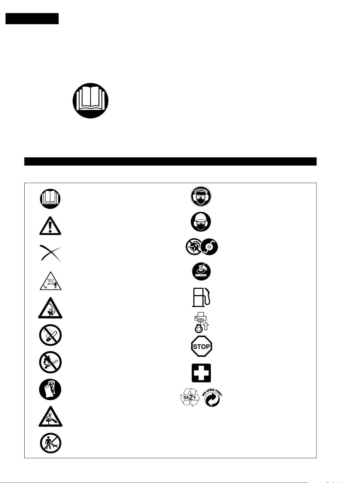
Read instruction Manual
Table of Contents Page
Symbols ...................................................................... 2
Safety instructions ..................................................... 3
Technical data ............................................................ 7
Designation of parts ................................................... 8
Mounting of handle ..................................................... 9
Mounting of protector ............................................... 10
Mounting of cutter blade or nylon cutting head ......... 11
Before start of operation .......................................... 12
Correct handling of machine ..................................... 14
Points in operation and how to stop ......................... 14
Resharpening the cutting tool ................................... 16
Servicing instructions ............................................... 18
Storage ..................................................................... 21
Wear eye and ear protection
(for String trimmer only)
Take Particular care and Attention
Forbidden
Keep distance
Flying object hazard
No Smoking
No open flame
Wear protective helmet, eye and ear
protection (for Brush Cutter only)
Do not use metal blades
(for String trimmer only)
Top permissible tool speed
Fuel (Gasoline)
Engine-Manual start
Emergency stop
First Aid
Protective gloves must be worn
Kickback
Keep the area of operation clear of all
persons and pets
Recycling
ON/START
I
O
2
OFF/STOP
SAFETY INSTRUCTIONS
General Instructions
– To ensure correct operation, user has to read this instruction manual to make
himself familiar with the handling of the Brush Cutter/String trimmer. Users
insufficiently informed will risk danger to themselves as well as others due to
improper handling.
– It is recommended only to lend the Brush Cutter/String trimmer to people who
have proven to be experienced with Brush Cutter/String trimmers.
Always hand over the instruction manual.
– First users should ask the dealer for basic instructions to familiarize oneself
with the handling of an engine powered cutter.
– Children and young persons aged under 18 years must not be allowed to
operate the Brush Cutter/String trimmer. Persons over the age of 16 years
may however use the device for the purpose of being trained only whilst
under supervision of a qualified trainer.
– Use Brush Cutter/String trimmers with the utmost care and attention.
– Operate the Brush Cutter/String trimmer only if you are in good physical
condition. Perform all work calmly and carefully. The user has to accept
liability for others.
– Never use the Brush Cutter/String trimmer after consumption of alcohol or
drugs, or if feeling tired or ill.
Intended use of the machine
– The Brush Cutter/String trimmer is only intended for cutter grass, weeds,
Bushes, undergrowth it should not be used for any other purpose such as
Edging or hedge cutting as this may cause injury.
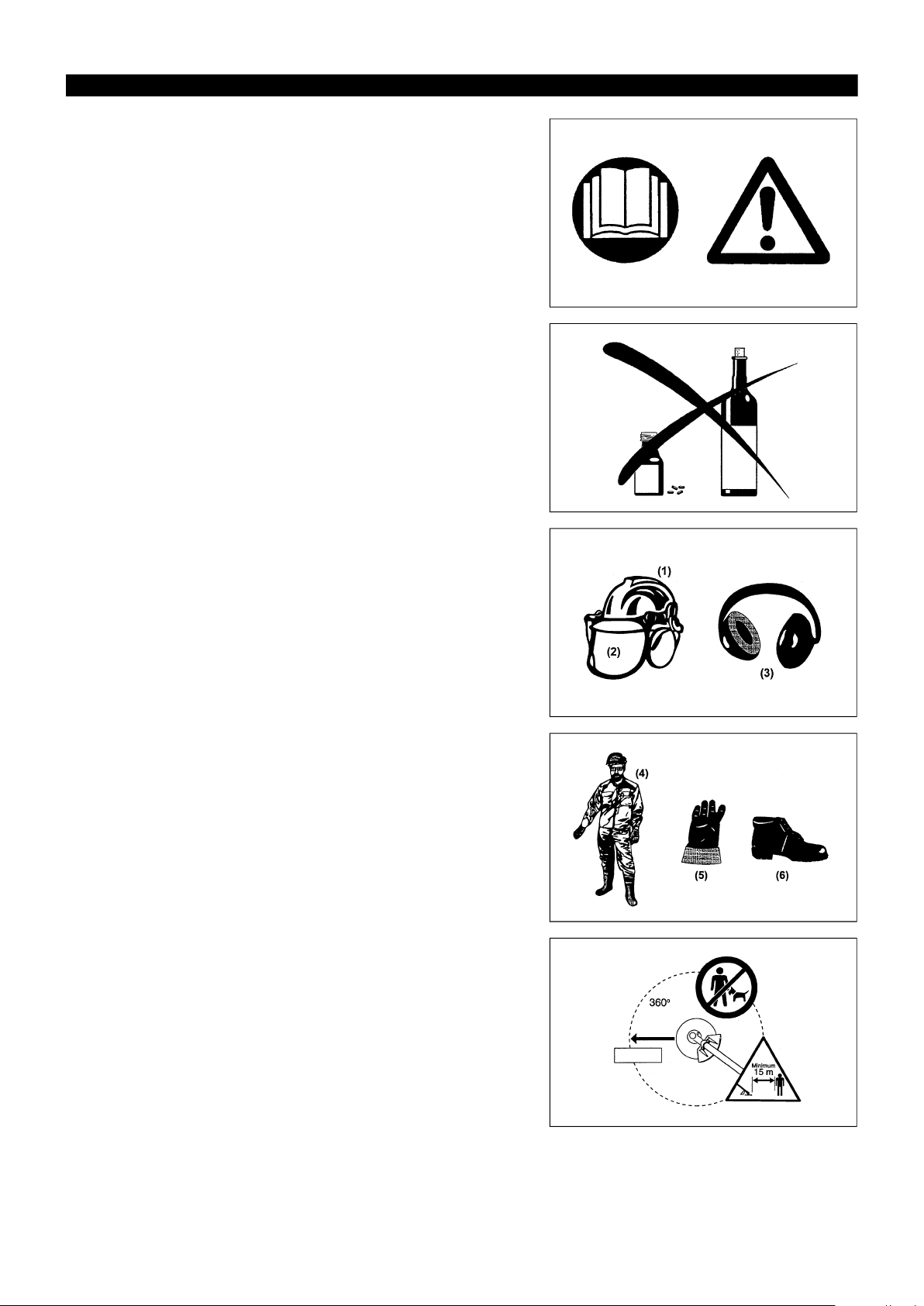
Personal protective equipment
– The clothing worn should be functional and appropriate, i.e. it should be tight-
fitting but not cause hindrance. Do not wear either jewelry or clothing which
could become entangled with bushes or shrubs.
– In order to avoid either head-, eye-, hand-or foot injuries as well as to protect
your hearing the following protective equipment and protective clothing must
be used during operation of the Brush Cutter/String trimmer.
– Always wear a helmet where there is a risk of falling objects. The protec-
tive helmet (1) is to be checked at regular intervals for damage and is to be
replaced at the latest after 5 years. Use only approved protective helmets.
– The visor (2) of the helmet (or alternatively goggles) protects the face from
flying debris and stones. During operation of the Brush Cutter/String trimmer
always wear goggles, or a visor to prevent eye injuries.
– Wear adequate noise protection equipment to avoid hearing impairment (ear
muffs (3), ear plugs etc.).
– The work overalls (4) protect against flying stones and debris.
We strongly recommend that the user wears work overalls.
– Special gloves (5) made of thick leather are part of the prescribed equipment
and must always be worn during operation of the Brush Cutter/String
trimmer.
– When using the Brush Cutter/String trimmer, always wear sturdy shoes (6)
with a non-slip sole. This protects against injuries and ensures a good
footing.
Starting up the brush cutter
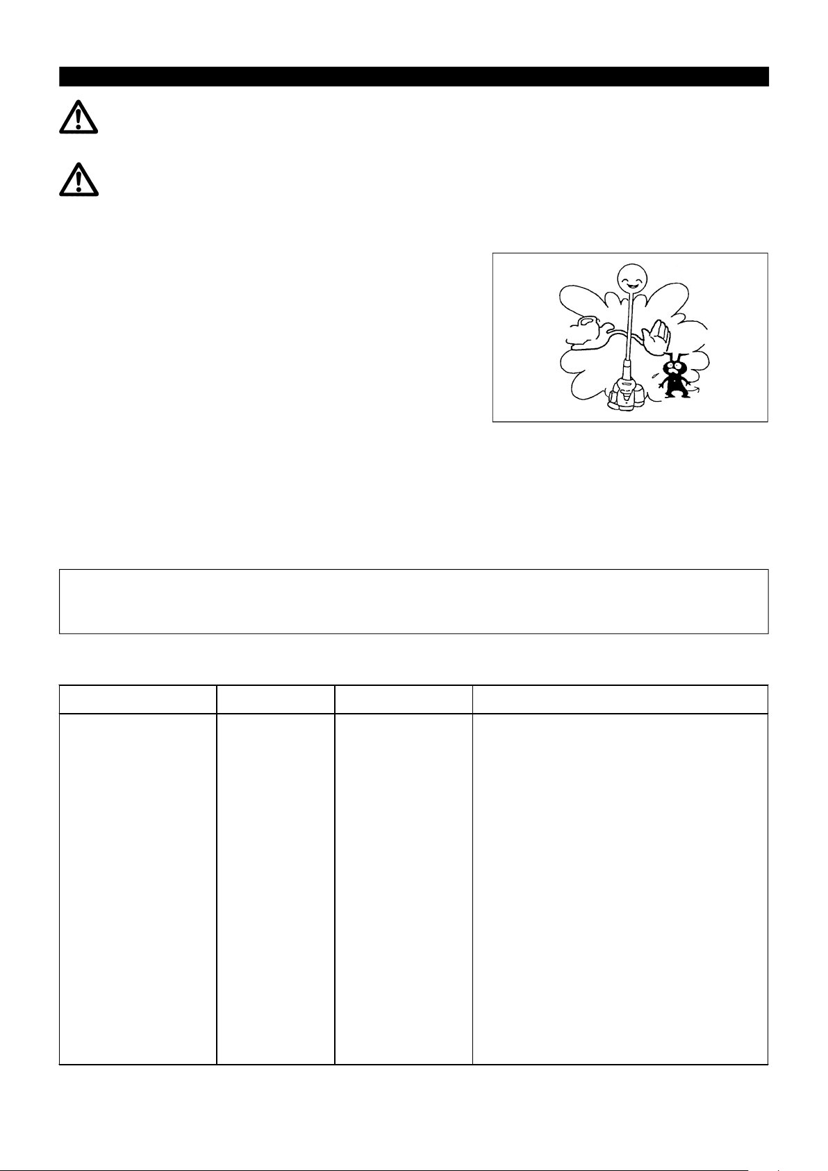
– Please make sure that there are no children or other people within a working
range of 15 meters (49ft), also pay attention to any animals in the working
vicinity.
– Before use always check that the Brush Cutter/String trimmer is safe for
operation:
Check the security of the cutting tool, the control lever for easy action and
check for proper functioning of the control lever lock.
– Rotation of the cutting tool during idling speed is not allowed. Check with
your dealer for adjustment if in doubt. Check for clean and dry handles and
test the function of the start/stop switch.
Diagrammatic figure
15Meter
3
Start the Brush Cutter/String trimmer only in accordance with the instructions.
Do not use any other methods for starting the engine!
– Use the Brush Cutter/String trimmer and the tools only for such applications
as specified.
– Only start the Brush Cutter/String trimmer engine, after the entire assembly is
done. Operation of the device is only permitted after all the appropriate
accessories are attached!
– Before starting make sure that the cutting tool has no contact with hard
objects such as branches, stones etc. as the cutting tool will revolve when
starting.
– The engine is to be switched off immediately in case of any engine problems.
– Should the cutting tool hit stones or other hard objects, immediately switch off
the engine and inspect the cutting tool.
– Inspect the cutting tool at short regular intervals for damage (detection of
hairline cracks by means of tapping-noise test).
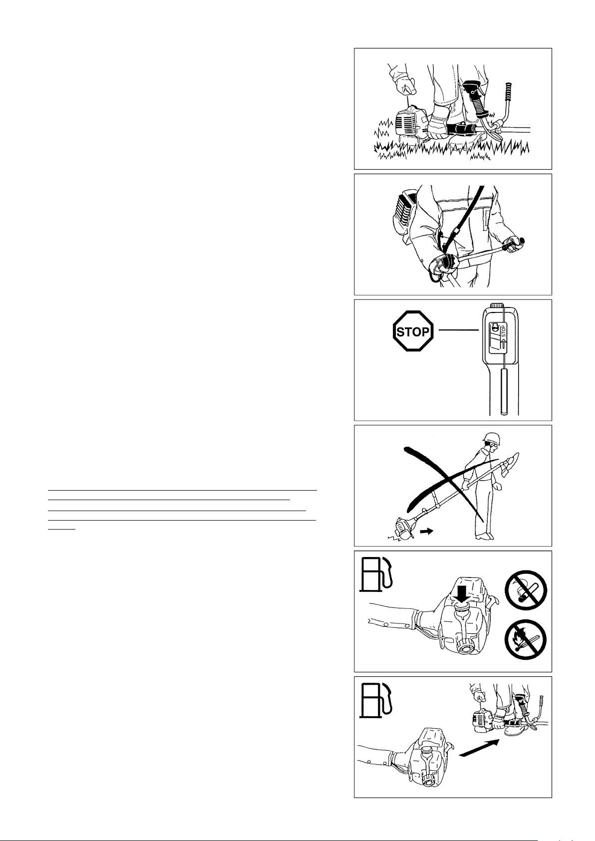
– Operate the Brush Cutter/String trimmer only with the shoulder strap
attached which is to be suitably adjusted before putting the Brush Cutter/
String trimmer into operation. It is essential to adjust the shoulder strap
according to the user’s size to prevent fatigue occurring during use. Never
hold the cutter with one hand during use.
– During operation always hold the Brush Cutter/String trimmer with both
hands.
Always ensure a safe footing.
– Operate the Brush Cutter/String trimmer in such a manner as to avoid
inhalation of the exhaust gases. Never run the engine in enclosed rooms
(risk of gas poisoning). Carbon monoxide is an odorless gas.
– Switch off the engine when resting and when leaving the Brush Cutter/
String trimmer unattended, and place it in a safe location to prevent danger to
others or damage to the machine.
– Never put the hot Brush Cutter/String trimmer onto dry grass or onto any
combustible materials.
– The cutting tool has to be equipped with it’s appropriate guard.
Never run the cutter without this guard!
– All protective installations and guards supplied with the machine must be
used during operation.
– Never operate the engine with faulty exhaust muffler.
– Shut off the engine during transport.
– During transport over long distances the tool protection included with the
equipment must always be used.
– Ensure safe position of the Brush Cutter/String trimmer during car transpor-
tation to avoid fuel leakage.
– When transporting the Brush Cutter/String trimmer, ensure that the fuel tank
is completely empty.
– When unloading the Brush Cutter/String trimmer from the truck, never drop
the Engine to the ground or this may severely damage the fuel tank.
– Except in case of emergency, never drop or cast the Brush Cutter/String
trimmer to the ground or this may severely damage the Brush Cutter/String
trimmer.
– Remember to lift the entire equipment from the ground when moving the
equipment. Dragging the fuel tank is highly dangerous and will cause
damage and leakage of fuel, possibly causing fire.
• Resting
• Transport
• Refuelling
• Maintenance
• Tool Replacement
Refuelling
– Shut off the engine during refuelling, keep away from open flames and do
not smoke.
– Avoid skin contact with mineral oil products. Do not inhale fuel vapor.
Always wear protective gloves during refuelling. Change and clean
protective clothing at regular intervals.
– Take care not to spill either fuel or oil in order to prevent soil contamination
(environmental protection). Clean the Brush Cutter/String trimmer immedi-
ately after fuel has been spilt.
– Avoid any fuel contact with your clothing. Change your clothing instantly if
fuel has been spilt on it (to prevent clothing catching fire).
– Inspect the fuel cap at regular intervals making sure that it can be securely
fastened and does not leak.
– Carefully tighten the fuel tank cap. Change location to start the engine (at
least 3 meters away from the place of refuelling).
– Never refuel in closed rooms. Fuel vapors accumulate at ground lever (risk of
explosions).
– Only transport and store fuel in approved containers. Make sure the fuel
stored is not accessible to children.
4
s
r
e
t
e
m
3
Method of operation
– Only use the Brush cutter/String trimmer in good light and visibility. During the
winter season beware of slippery or wet areas, ice and snow (risk of
slipping). Always ensure a safe footing.
– Never cut above waist height.
– Never stand on a ladder and run the Brush cutter/String trimmer.
– Never climb up into trees to perform cutting operation with the Brush cutter/
String trimmer.
– Never work on unstable surfaces.
– Remove sand, stones, nails etc. found within the working range.
Foreign particles may damage the cutting tool and can cause dangerous
kick-backs.
– Before commencing cutting, the cutting tool must have reached full working
speed.
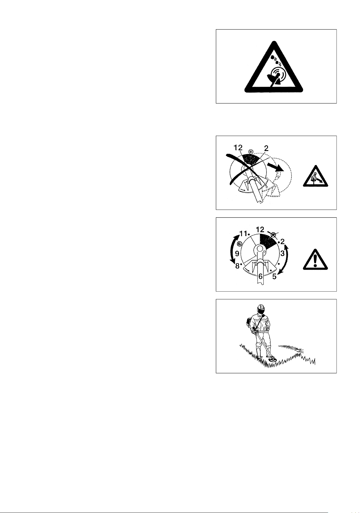
Kickback
– When operating the brush cutter, uncontrolled kickback may occur.
– This is particularly the case when attempting to cut within a blade segment
between 12 and 2 o’clock.
– Never apply the brush cutter within a segment between 12 and 2 o’clock.
– Never apply this segment of the brush cutter blade to solids, such as
bushes and trees, etc., having a diameter in excess of 3 cm or the brush
cutter will be deflected at great force with the risk of injuries.
Kickback prevention
To avoid kickbacks, observe the following:
– Operation within a blade segment between 12 and 2 o’clock presents
positive hazards, especially when using metal cutting tools.
– Cutting operations within a blade segment between 11 and 12 o’clock, and
between 2 and 5 o’clock, must only be performed by trained and experi-
enced operators, and then only at their own risk.
Easy cutting with almost no kickback is possible within a blade segment
between 8 and 11 o’clock.
Cutting Tools
Employ only the correct cutting tool for the job in hand.
Caution:
Kickback
Diagrammatic
flgure
Diagrammatic
flgure
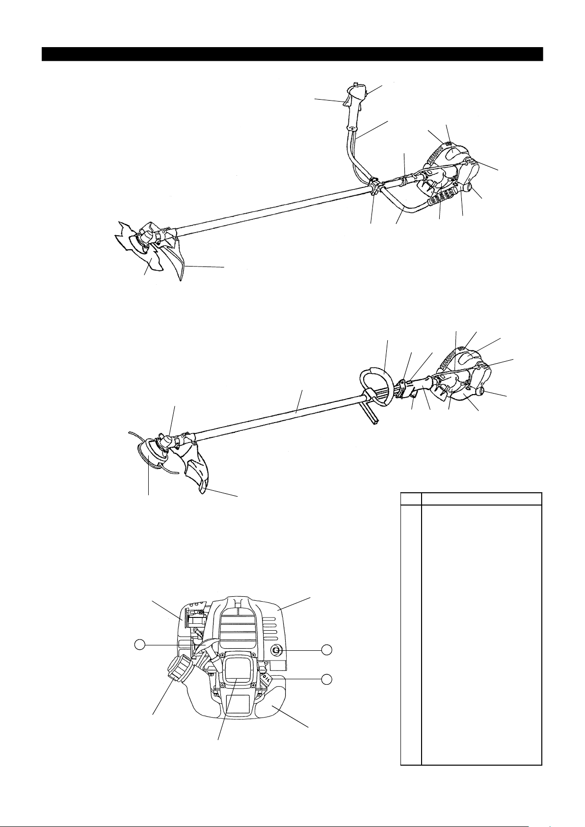
EM4250/EM4250CA, EM4251/EM4251CA with cutter blade (Star Blade (4
teeth), Eddy Blade (8 teeth)), Nylon cutting head
For cutting thick materials, such as weed, high grass, bushes, shrubs,
underwood, thicket etc. (max. 2 cm dia. thickness). Perform this cutting work
by swinging the brush cutter evenly in half-circles from right to left (similar to
using a scythe).
Maintenance instructions
– The condition of the cutter, in particular of the cutting tool of the protective
devices and also of the shoulder strap must be checked before commencing
work. Particular attention is to be paid to the cutting blades which must be
correctly sharpened.
– Turn off the engine and remove spark plug connector when replacing or
sharpening cutting tools, and also when cleaning the cutter or cutting tool.
5

Never straighten or weld damaged cutting tools.
– Operate the Brush cutter/String trimmer with as little noise and contamination
as possible. In particular check the correct setting of the carburetor.
– Clean the Brush cutter/String trimmer at regular intervals and check that all
screws and nuts are well tightened.
– Never service or store the Brush cutter/String trimmer in the vicinity of naked
flames.
– Always store the Brush cutter/String trimmer in locked rooms and with an
emptied fuel tank.
Observe the relevant accident prevention instructions issued by the relevant
trade associations and by the insurance companies.
Do not perform any modifications on the Brush cutter/String trimmer as this
will endanger your safety.
The performance of maintenance or repair work by the user is limited to those
activities as described in the instruction manual. All other work is to be done
by an Authorized Service Agent. Use only genuine spare parts and
accessories released and supplied by MAKITA.
Use of non-approved accessories and tools means increased risk of
accidents.
MAKITA will not accept any liability for accidents or damage caused by the
use of non-approved cutting tools and fixing devices of cutting tools, or
accessories.
First Aid
In case of accident make sure that a first-aid box is available in the vicinity of
the cutting operations. Immediately replace any item taken from the first aid
box.
When asking for help, please give the following information:
– Place of accident
– What happened
– Number of injured persons
– Kind of injuries
– Your name
Packaging
The MAKITA Brush cutter/String trimmer will be delivered in two protective
cardboard boxes to prevent transport damage. Cardboard is a basic raw
material and is therefore consequently reusable or suitable for recycling
(waste paper recycling).
6

TECHNICAL DATA EM4250, EM4251
Model
EM4251/EM4251CA EM4250/EM4250CA
Loop handle U handle
Dimensions : length x width x height (without cutting blade) mm
Mass (without plastic guard and cutting blade) kg
Volume (fuel tank) L
Volume (oil tank) L
Engine displacement cc
Maximum engine performance HP
Engine speed at recommended max. spindle speed /min
Maximum spindle speed (corresponding) /min
Maximum fuel consumption kg/h
Maximum specific fuel consumption g/HPh
Idling speed /min
Clutch engagement speed /min
Carburetor type
1760x330x265 1760x600x405
5.2 5.4
0.5
0.08
24.5
0.885 at 7000 /min
8500
6500
0.33
304
3000
3750
WALBRO WYL
Ignition system type
Spark plug type
Electrode gap mm
Idling m/s
Right handle
Vibration per
(Rear grip)
ISO 7916
1)
Left handle
(Front grip)
Sound pressure level average to ISO 7917
Sound power level average to ISO 10884
Racing or W.O.T m/s
Idling m/s
Racing or W.O.T m/s
1)
1)
Fuel
Engine Oil
Gear ratio
dB
dB
Solid state ignition
NGK CMR6A
0.7 - 0.8
2
2
2
2
2.59 4.72
6.27 4.7
3.26 3.83
7.24 7.56
87.7 87.7
97.7 97.7
Automobile gasoline
SAE 10W-30 oil of API Ciassification,
Class SF or higher (4-stroke engine for automobile)
14/19
7
DESIGNATION OF PARTS
ԛ
Ԣ
EM4250/EM4250CA
Brush Cutter
Ԩ
EM4251/EM4251CA
String trimmer
Ԧ
ԥ
Ԥ
ԧ
ԡ
ԣ
ԡ
Ԡ
Ԡ
Ԣ
ԝ
ԟ
ԛ
Ԟ
Ԝ
Ԟ
ԣ
Ԙ
ԝ
Ԙ
Ԛ
ԫ
Ԝ
Ԛ
ԫ
ԩ
Ԛ
ԫ
ԙ
ԥ
ԝ
Ԙ
GB DESIGNATION OF PARTS
1 Fuel Tank
2 Rewind Starter
3 Air Cleaner
4 I-O Switch (on/off)
5 Spark Plug
6 Exhaust Muffler
7 Clutch Case
8 Rear Grip
9 Hanger
10 Handle
11 Control Lever
12 Control Cable
13 Shaft
14 Protector
15 Gear Case/Head Case
16 Handle Holder
17 Cutter Blade
18 Nylon Cutting Head
20 Fuel Filler Cap
21 Starter Knob
24 Exhaust Pipe
25 Oil Gauge
8
MOUNTING OF HANDLE
CAUTION: Before doing any work on the brush cutter, always stop the
engine and pull the spark plug connector off the spark plug.
Always wear protective gloves!
CAUTION: Start the brush cutter only after having assembled it completely.
For machines with U Handle models
– Insert the handle bar into the handle holder, making sure that the boss in the
handle holder fits into the hole in the handle.
– After the handle bar is in place, tighten the four bolts (M5 x 25).
NOTE: Be sue the bolts are tight, but do not overtighten.
– Fit the control cable (together with the earth cord) to the handle with two
clips (3).
– Avoid any tendency of the control cable to loop at the handle bar.
e
n
i
g
n
e
o
t
(3)
For machines with Loop Handle models
– Fix a barrier to the left side of the machine together with the handle for
operator's protection.
– Do not adjust position of the loop handle too close to the control grip. Keep
not less than 25cm distance between the handle and the grip.
(a distance collar is provided for this purpose.)
to engine
9
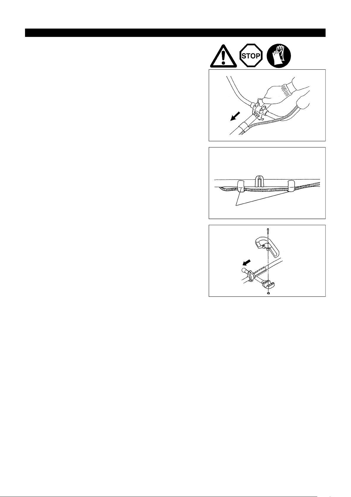
MOUNTING OF PROTECTOR
To meet the applicable safety provisions, only the tool/
protector combinations as indicated in the table must
be used.
Be sure to use genuine MAKITA cutter blades
or nylon cutting head.
– The cutter blade must be well polished, free of
cracks or breakage. If the cutter blade hits against a
stone during operation, stop the engine and check
the blade immediately.
– Polish or replace the cutter blade every three hours
of operation.
– If the nylon cutting head hits against a stone during
operation, stop the engine and check the nylon
cutting head immediately.
Star Blade
PART NO. 6208501400
EM 4250/EM4250CA
Protector for metal blades
PART NO. 6258028002 PART NO. 6258061001
Protector for metal blades
(Use of protector for metal
blade/cord cutter)
CAUTION : The appropriate protector must always be
installed, for your own safety and in order
to comply with accident-prevention
regulations.
Operation of the equipment without the
guard being in place is not permitted.
Nylon cutting head
For EM4250/EM4250CA
– The outside diameter of the cutter blade must be
230mm (9-1/16"). Never use any blades surpassing
230mm (9-1/16") in outside diameter.
PART NO. 6218014001
For EM4250/EM4250CA, EM4251/EM4251CA
– Install the clamp (3) on the shaft so that the projection of the clamp (3) is
inserted into the opening between the gear case (1) and the shaft.
Secure the protector (4) with the installation bolts M6 x 30 (2) and screw
M5 x 8 (5).
EM 4251/EM4251CA
Protector for cord cutter
PART NO. 6218008003 PART NO. 6258060001
Protector for cord cutter
(Use of protector for metal
blade/cord cutter)
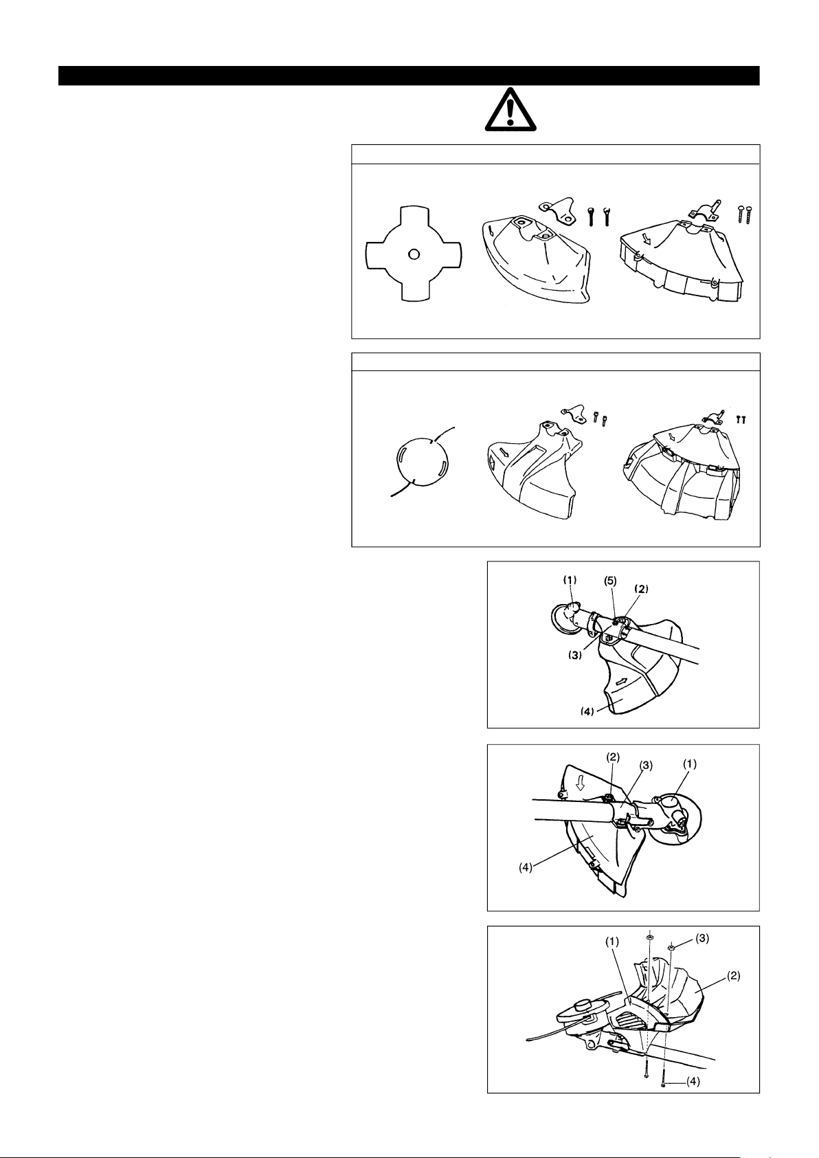
Use of protector for metal blade / cord cutter.
– In use of the metal blade, fasten the protector (4) to the clamp (3) with two
bolts M6 x 30 (2).
NOTE : Tighten the right and left bolts evenly so that the gap between the
clamp (3) and the protector (4) will be constant.
Otherwise, the protector sometimes may not function as specified.
– In use of the cord cutter, insert the protector (2) into the protector (1), and
fasten them with two screw (4) and two nuts (3).
10
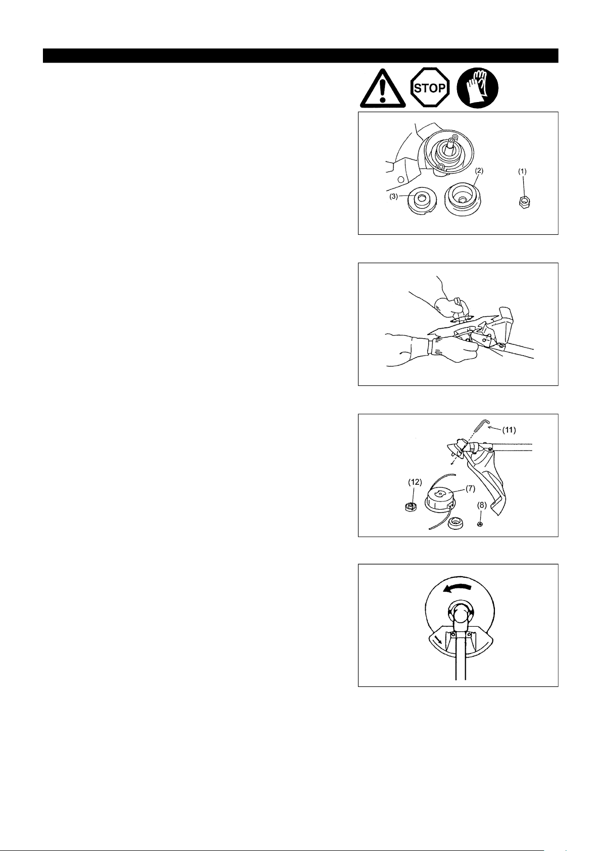
MOUNTING OF CUTTER BLADE OR NYLON CUTTER HEAD
Turn the machine upside down, and you can replace the cutter blade easily.
For EM4250/EM4250CA, EM4251/EM4251CA
– Insert the hex wrench through the hole in the gear case and rotate the
receiver washer (3) until it is locked with the hex wrench.
– Loosen the nut (1) (left-hand thread) with the socket wrench and remove
the nut (1), and clamp washer (2).
For EM4250/EM4250CA with the hex wrench still in place.
– Mount the cutter blade onto the shaft so that the guide of the receiver
washer (3) fits in the arbor hole in the cutter blade. Install the clamp washer
(2) and secure the cutter blade with the nut (1).
[Tightening torque: 13 - 23 N-m]
NOTE: Always wear gloves when handling the cutter blade.
NOTE: The cutter blade-fastening nut (with spring washer) is a consumable
part. If there appears any wear or deformation on the spring washer,
replace the nut.
Hex wrench
Mounting of nylon cutting head
For EM4251/EM4251CA
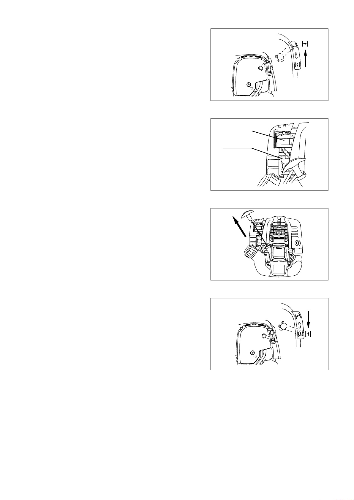
– To install the nylon cutting head (7), remove the tightening nut (8).
– Insert the socket-head wrench (11) through the hole in the gear case and
tum the support washer until it will be locked with its notch (12) (or the shaft
will be locked).
– Then screw the nylon cutting head onto the shaft by turning it counter-
clockwise.
– Remove the socket-head wrench.
– Make sure that the blade is the left way up.
Rotation
11
BEFORE START OF OPERATION
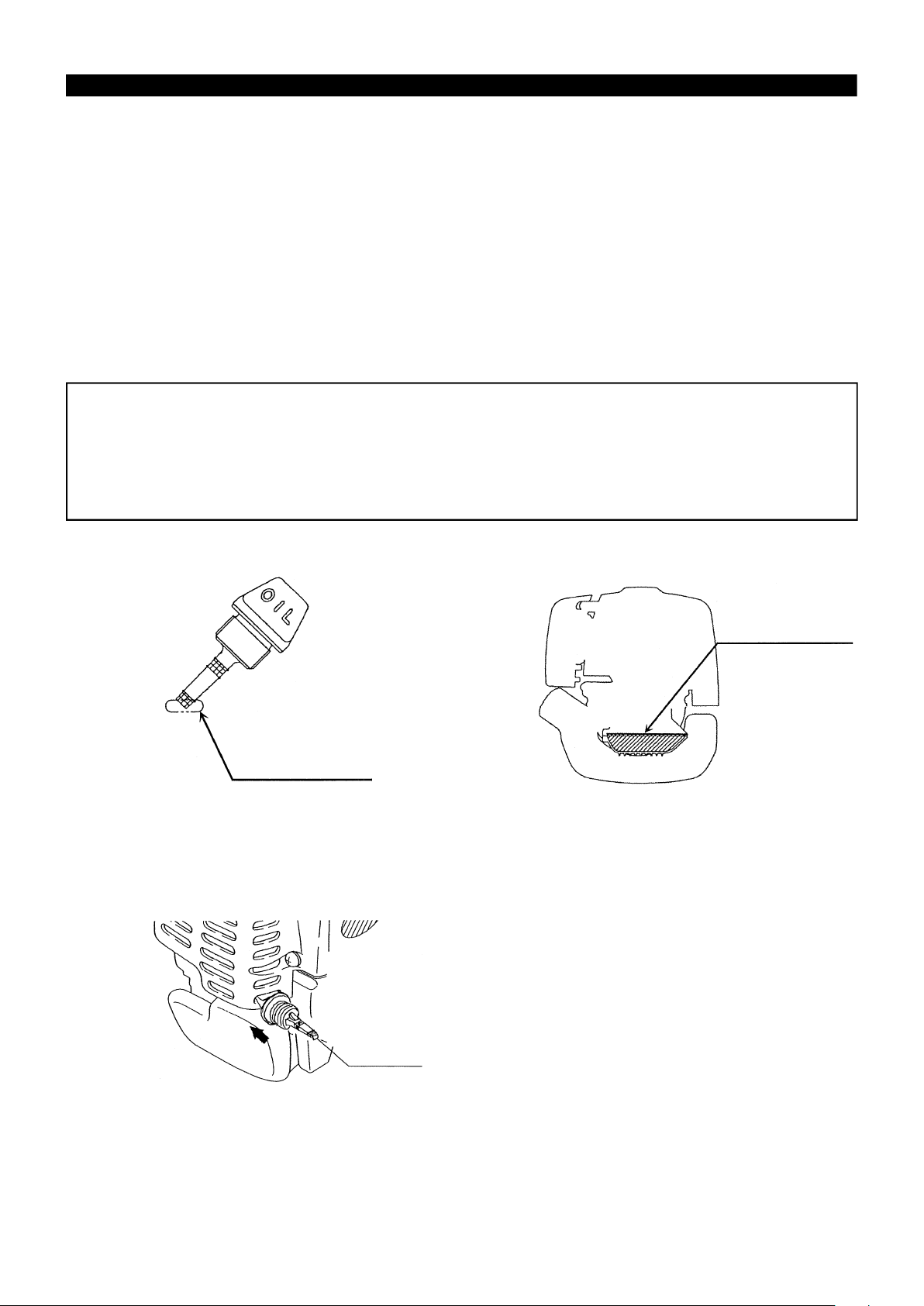
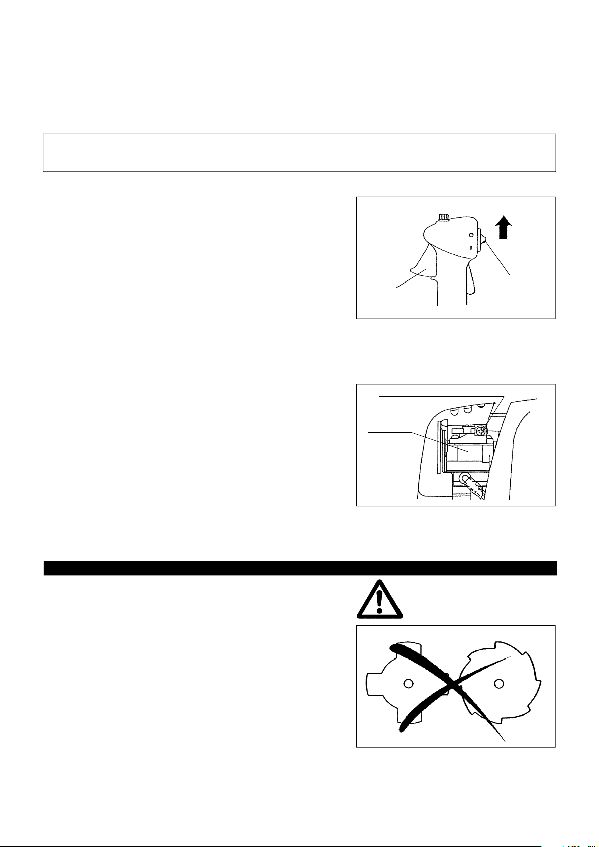
Inspection and Refill of Engine Oil
– Perform the following procedure, with the engine cooled down.
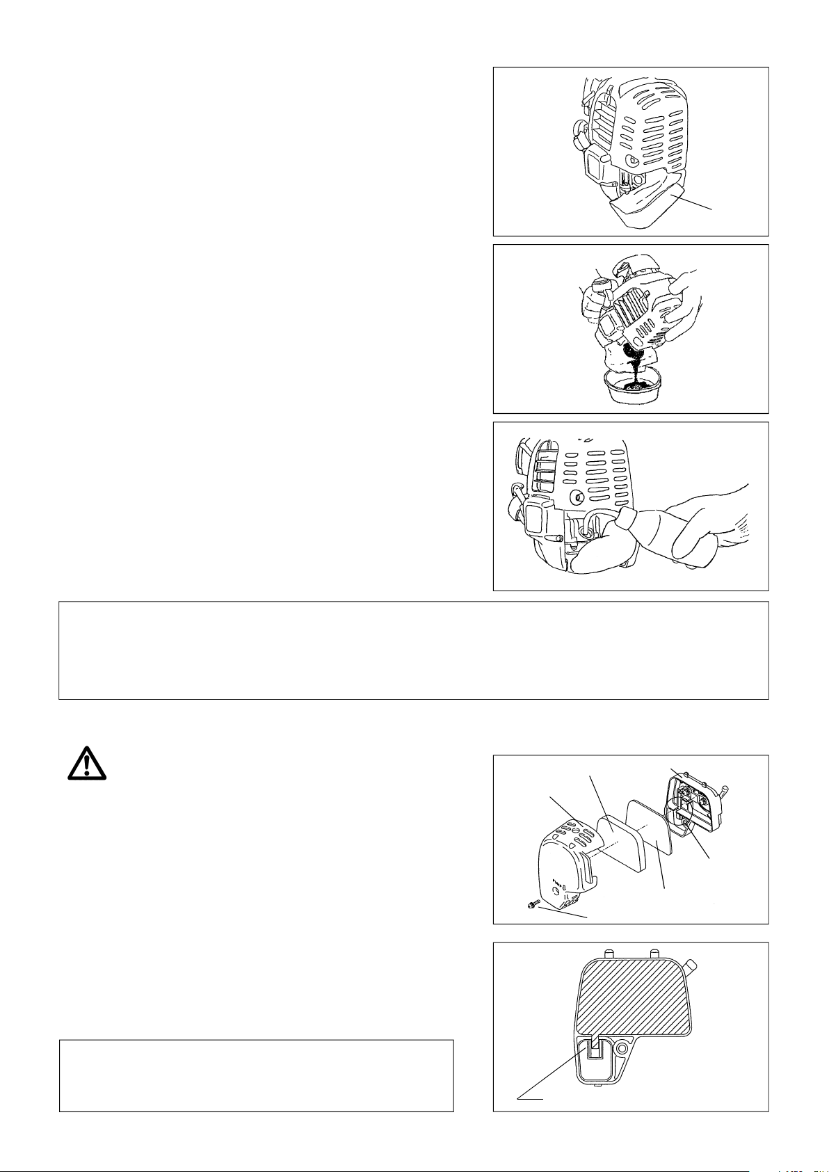
– While keeping the engine level, remove the oil gauge, and confirm that the oil is filled within the upper and lower limit marks.
When the oil is in short in such a way that the oil gauge touches the oil only by its tip, in particular with the oil gauge remaining inserted in
the crankcase without screwing-in (Fig. 1), refill new oil near the port (Fig. 2).
– For reference, the oil refill time is about 10h (10 times or 10 tanks of oil refill).
– If the oil changes in color or mixes with dirt, replace it with new one. (For the interval and method of replacement, refer to P 18)
Recommended oil: SAE 10W-30 oil of API Classification, Class SF or higher (4-stroke engine for automobile)
Oil volume: Approx. 0.08L
Note: If the engine is not kept upright, oil may go into around the engine, and may be refilled excessively.
If the oil is filled above the limit, the oil may be contaminated or may catch fire with white.
Point 1 in Replacement of Oil “Oil Gauge”
– Remove dust or dirt near the oil refill port, and detach the oil gauge.
– Keep the detached oil gauge free of sand or dust. Otherwise, any sand or dust adhering to the oil gauge may cause irregular oil
circulation or wear on the engine parts, which will result in troubles.
– As an example to keep the oil gauge clean, it is recommended to insert the oil gauge on its knob side into the engine cover, as
shown in Fig.3.
If oil adheres around
this tip, refill new oil.
Fig.1
Upper limit
(Edge of oil refill port)
Fig.2
Oil gauge
Fig.3
12
(1) Keep the engine level, and detach the oil gauge.
(2) Fill oil up to the edge of the oil refill port. (Refer to Fig.2 of the preceding
page).
Feed oil with the lubricant refill container.
(3) Securely tighten the oil gauge. Insufficient tightening may cause oil
leakage.
Point 2 in Replacement of Oil: “If oil spills out”
– If oil spills out between the fuel tank and engine main unit, the oil is sucked into through the cooling air intake port, which will
contaminate the engine. Be sure to wipe out spilt oil before start of operation.
REFUELING
Handling of Fuel
It is necessary to handle fuel with utmost care. Fuel may contain substances similar to solvents. Refueling must be performed in a sufficiently
ventilated room or in the open air. Never inhale fuel vapor, and keep fuel away from you. If you touch fuel repeatedly or for a long time, the
skin becomes dry, which may cause skin disease or allergy. If fuel enters into the eye, clean the eye with fresh water. If your eye remains
still irritated, consult your doctor.
Storage Period of Fuel
Fuel should be used up within a period of 4 weeks, even if it is kept in a special container in a well-ventilated shade.
If a special container is not used or if the container is not covered, fuel may deteriorate in one day.
STORAGE OF MACHINE AND REFILL TANK
– Keep the machine and tank at a cool place free from direct sunshine.
– Never keep the fuel in the cabin or trunk.
Fuel
The engine is a four-stroke engine. Be sure to use an automobile gasoline (regular gasoline or premium gasoline).
Points for Fuel
– Never use a gasoline mixture which contains engine oil. Otherwise, it will cause excessive carbon accumulation or mechanical
troubles.
– Use of deteriorated oil will cause irregular startup.
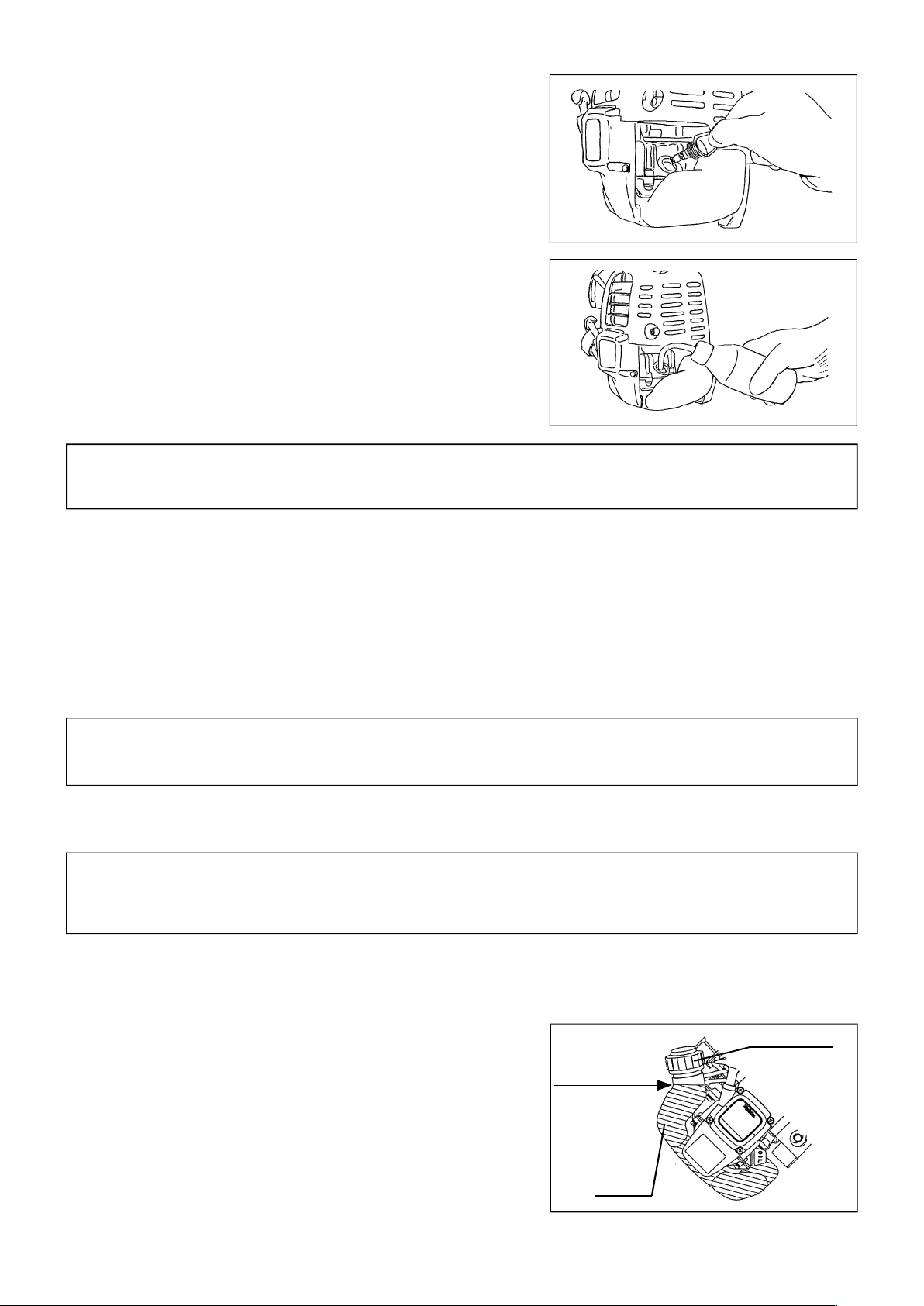
Refueling
WARNING: INFLAMMABLES STRICTLY PROHIBITED
Gasoline used: Automobile gasoline (unleaded gasoline)
– Loosen the tank cap a little so that there will be no difference in atmospheric
pressure.
– Detach the tank cap, and refuel, discharging air by tilting the fuel tank so that
the refuel port will be oriented upward. (Never refill fuel full to the oil refill
port.)
– Wipe well the periphery of the tank cap to prevent foreign matter from
entering into the fuel tank.
– After refueling, securely tighten the tank cap.
٨
If there is any flaw or damage on the tank cap, replace it.
٨
The tank cap is consumable, and therefore should be renewed every two to
three years.
13
Fuel tank cap
Fuel upper limit
Fuel tank
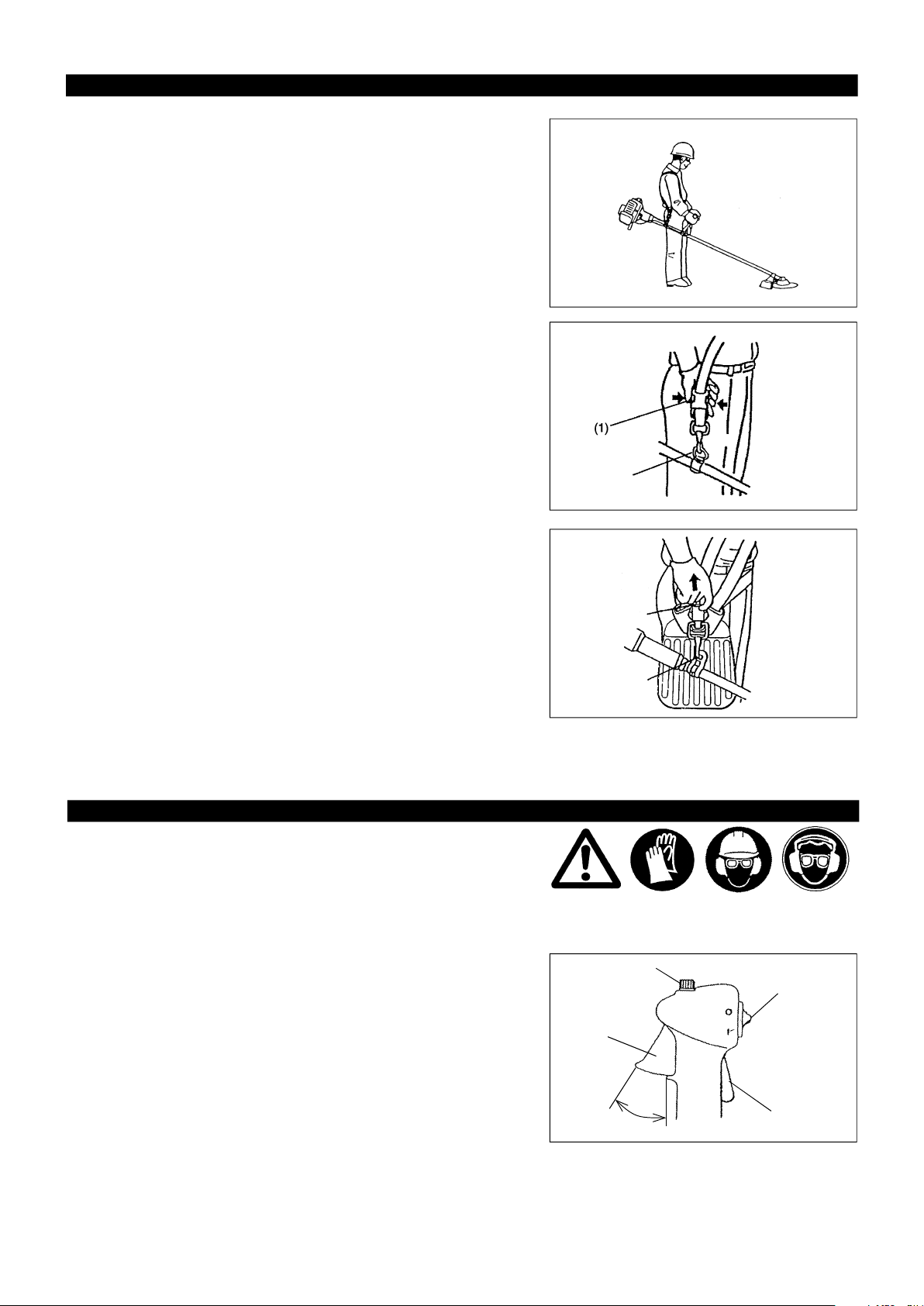
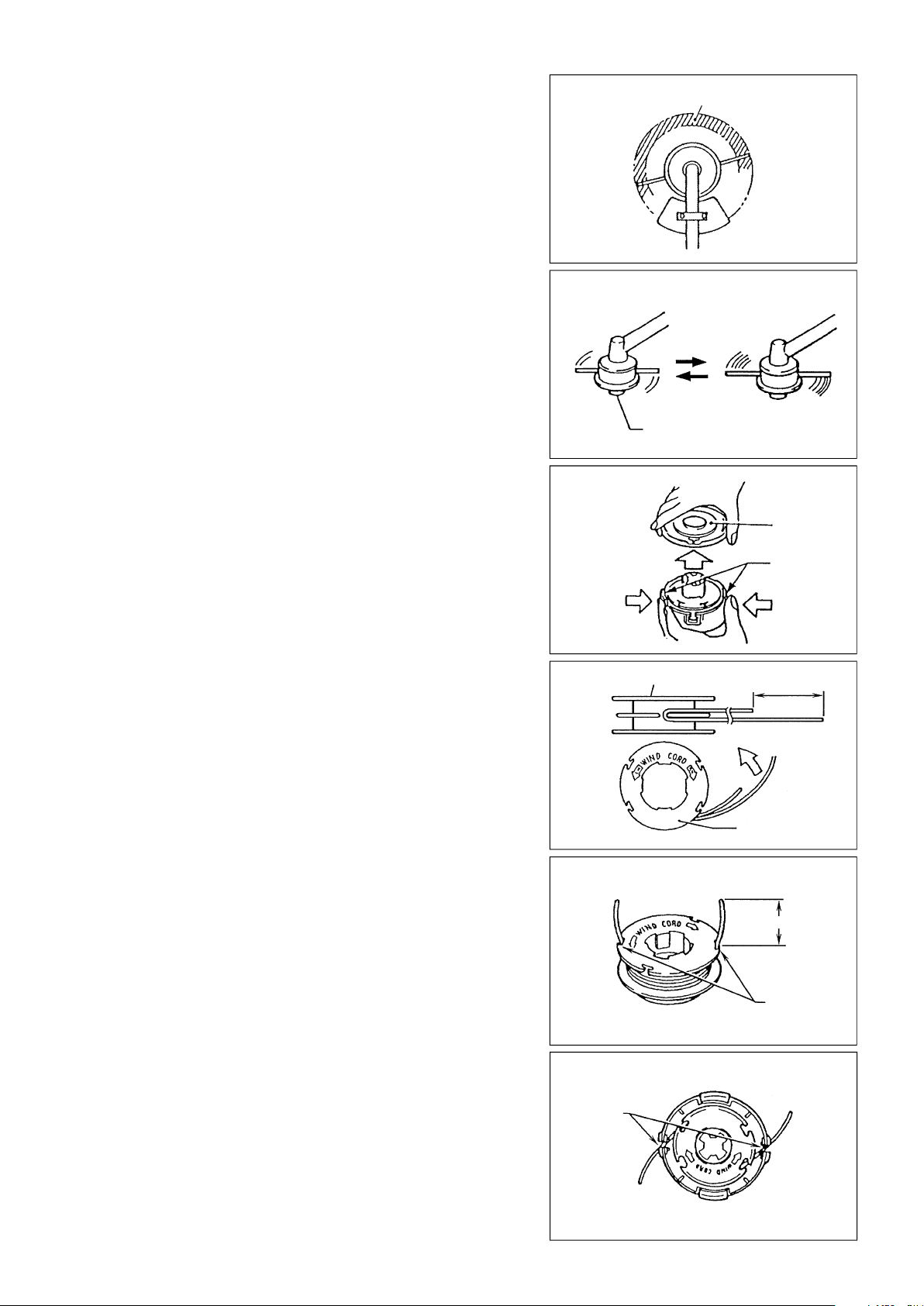
CORRECT HANDLING OF MACHINE
Attachment of shoulder strap
– Adjust the strap length so that the cutter blade will be kept parallel with the
ground.
Detachment
– In an emergency, push the notches (1) at both sides, and you can detach
the machine from you.
Be extremely careful to maintain control of the machine at this time. Do not
allow the machine to be deflected toward you or anyone in the work vicinity.
WARNING: Failure to maintain complete control of the machine at all could
result in serious bodily injury or DEATH.
For EM4250/EM4250CA
– In case of emergency, remove the emergency detachment lever (2) by
pulling strongly with a finger. The machine sill detach from body.
Be extremely careful to maintain control of the machine at this time. Do not
allow the machine to be deflected toward you or anyone in the work
vicinity.
WARNING: Failure to maintain complete control of the machine at all could
result in serious bodily injury or DEATH.
Hanger
(2)
Hanger
POINTS IN OPERATION AND HOW TO STOP
Observe the applicable accident prevention regulations!
STARTING
Move at least 3m away from the place of refuelling. Place the brush cutter on a clean piece of ground taking care that the cutting tool does
not come into contact with the ground or any other objects.
A:Cold start
1) Set this machine on a flat space.
Throttle control dial
Throttle lever (6)
Low speed
I-O switch (1)
OPERATION
Lock-off lever
High speed
14
For machine with U Handle or Loop Handle
1) Set the I-O switch (1) to OPERATION.
2) Choke lever
Close the choke lever.
Choke opening:
– Full closing in cold or when the engine is cold.
– Full or half opening in restart just after stop of operation.
3) Primer pump
Continue to push the primer pump until fuel enters into the primer pump. (In
general, fuel enters into the primer pump by 7 to 10 pushes.)
If the primer pump is pushed excessively, an excess of gasoline returns to
the fuel tank.
CLOSE
Carburetor
Primer Pump
4) Recoil starter
– Pull the start knob gently until it is hard to pull (compression point).
Then, return the start knob, and pull it strongly.
– Never pull the rope to the full. Once the start knob is pulled, never
release your hand immediately. Hold the start knob until it returns to its
original point.
5) Choke lever
When the engine starts, open the choke lever.
– Open the choke lever progressively while checking the engine
operation. Be sure to open the choke lever to the full in the end.
– In cold or when the engine is cooled down, never open the choke lever
suddenly. Otherwise, the engine may stop.
6) Warm-up operation
Continue warm-up operation for 2 to 3 minutes.
OPEN
Note: – If the starter handle is pulled repeatedly when the choke lever remains at “START” position, the engine will not start easily due to
excessive fuel intake.
– In case of excessive fuel intake, remove the spark plug and pull the starter handle slowly to remove excess fuel. Also, dry the
electrode section of the spark plug.
Caution during operation:
If the throttle lever is opened fully in a no-load operation, the engine rotation is increased to 10,000/min or more. Never operate the engine at
a higher speed than required and at an approximate speed of 6,000 - 8,500/min.
15
B: Startup after warm-up operation
1) Push the primer pump repeatedly.
2) Keep the throttle lever at the idling position.
3) Pull the recoil starter strongly.
4) If it is difficult to start the engine, open the throttle by about 1/3.
Pay attention to the cutter blade which may rotate.
Attention in Operation
When the engine is operated upside down, white smoke may come out from the muffler.
STOPPING
1) Release the throttle lever (6) fully, and when the engine rpm has lowered,
set the I-O switch to STOP the engine will now stop.
2) Be aware that the cutting head may not stop immediately and allow it to
slow down fully.
Throttle lever (6)
ADJUSTMENT OF LOW-SPEED ROTATION (IDLING)
When it is necessary to adjust the low-speed rotation (idling), perform it by the carburetor adjusting screw.
CHECKUP OF LOW-SPEED ROTATION
– Set the low-speed rotation to 3000/min.
If it is necessary to change the rotation speed, regulate the adjusting screw
(illustrated on the left), with Phillips screwdriver.
– Turn the adjusting screw to the right, and the engine rotation will increase.
Turn the adjusting screw to the left, and the engine rotation will drop.
– The carburetor is generally adjusted before shipment. If it is necessary to
readjust it, please contact Authorized Service Agent.
Adjusting screw
Carburetor
STOP
I-O switch (1)
RESHARPENING THE CUTTING TOOL
CAUTION : The cutting tools mentioned below must only be resharpened by
– cutter blade (star blade (4 teeth), eddy blade (8 teeth))
An expert resharpening and balancing service is provided by Authorized
Service Agents.
NOTE : To increase the service life of the cutter blade (star blade, eddy blade)
an authorized facility. Manual resharpening will result in imbalances of the cutting tool causing vibrations and damage to the
equipment.
it may be turned over once, until both cutting edges have become
blunt.
16
NYLON CUTTING HEAD
The nylon cutting head is a dual string trimmer head capable of both automatic
and bump & feed mechanisms.
The nylon cutting head will automatically feed out the proper length of nylon
cord by the changes in centrifugal force caused by increasing or decreasing
rpms. However, to cut soft grass more efficiently, bump the nylon cutting
head against the ground to feed out extra cord as indicated under operation
section.
Operation
– Increase the nylon cutting head speed to approx. 6,000/min.
Low speed (under 4,800/min) is not suitable, the nylon cord will not feed out
properly at low speed.
– The most effective cutting area is shown by the shaded area.
If the nylon cord does not feed out automatically proceed as follows:
1. Release the throttle lever to run the engine idle and then squeeze the
throttle lever fully. Repeat this procedure until the nylon cord feeds out to
the proper length.
2. If the nylon cord is too short to feed out automatically with the above
procedure, bump the knob of the nylon cutting head against the ground to
feed out the nylon cord.
3. If the nylon cord does not feed out with procedure 2, rewind/replace the
nylon cord by following the procedures described under “Replacing the
nylon cord”.
Replacing the nylon cord
– First, stop the engine.
– Press on the housing latches inward to lift off the cover, then remove the
spool.
Most effective cutting area
Idle speed
Knob
Full speed
Cover
Latches
– Hook the center of new nylon cord into the notch in the center of the spool,
with one end of the cord extending about 80mm (3-1/8") more than the other.
Then wind both ends firmly around the spool in the direction of the head
rotation (left-hand direction indicated by LH and right-hand direction by RH
on the side of the spool).
– Wind all but about 100mm (3-15/16") of the cords, leaving the ends tempo-
rarily hooked through a notch on the side of the spool.
Press
Spool
Press
80mm(3-1/8”)
For left hand rotation
Spool
100mm(3-15/16”)
Notches
– Mount the spool in the housing so that the grooves and protrusions on the
spool match up with those in the housing. Keep the side with letters on the
spool visible on the top. Now, unhook the ends of the cord from their
temporary position and feed the cords through the eyelets to come out of the
housing.
17
Eyelets
– Align the protrusion on the underside of the cover with the slots of the
eyelets.
Then push cover firmly onto the housing to secure it.
SERVICING INSTRUCTIONS
Cover
Protrusion
Slot of eyelet
CAUTION : Before doing any work on the Brush cutter/Grass trimmer, always stop the engine and pull the plug cap off the spark plug (see
To ensure a long service life and to avoid any damage to the equipment, the following servicing operations should be performed at regular
intervals.
“checking the spark plug”).
Always wear protective gloves!
Daily checkup and maintenance
– Before operation, check the machine for loose screws or missing parts. Pay particular attention to the tightness of the cutter blade or
nylon cutting head.
– Before operation, always check for clogging of the cooling air passage and the cylinder fins.
Clean them if necessary.
– Perform the following work daily after use:
• Clean the Brush cutter/Grass trimmer externally and inspect for damage.
• Clean the air filter. When working under extremely dusty conditions, clean the filter the severall times a day.
• Check the blade or the nylon cutting head for damage and make sure it is firmly mounted.
• Check that there is sufficient difference between idling and engagement speed to ensure that the cutting tool is at a standstill while the
engine is idling (if necessary reduce idling speed).
If under idling conditions the tool should still continue to run, consult your nearest Authorized Service Agent.
– Check the functioning of the I-O switch, the lock-off lever, the control lever, and the look button.
REPLACEMENT OF ENGINE OIL
Deteriorated engine oil will shorten the life of the sliding and rotating parts to a great extent. Be sure to check the period and quantity of
replacement.
ATTENTION : In general, the engine main unit and engine oil still remain hot just after the engine is stopped. In replacement of oil,
Note: If the oil filled above the limit, it may be contaminated or may catch fire with white smoke.
Interval of replacement : Initially, every 20 operating hours, and subsequently every 50 operating hours
Recommended oil : SAE10W-30 oil of API Classification SF Class or higher (4-stroke engine oil for automobile)
confirm that the engine main unit and engine oil are sufficiently cooled down. Otherwise, there may remain a risk of
scald.
In replacement, perform the following procedure.
1) Confirm that the tank cap is tightened securely.
2) Detach the oil gauge.
Keep the oil gauge free from dust or dirt.
Fuel tank cap
Oil gauge
18
3) Place waste or paper near the oil refill port.
4) Detach the oil gauge, and drain oil, tilting the main unit toward the oil refill
port.
Drain oil in a container.
5) Keep the engine level, and feed new oil up to the edge of the oil refill port.
In refill, use a lubricant refill container.
6) After refill, securely tighten the oil gauge. Insufficient tightening of the oil
gauge will lead to oil leakage.
Waste or paper
POINTS ON OIL
– Never discard replaced engine oil in garbage, earth or sewage ditch. Disposal of oil is regulated by law. In disposal, always follow
the relevant laws and regulations. For any points remaining unknown, contact Authorized Service Agent.
– Oil will deteriorate even when it is kept unused. Perform inspection and replacement at regular intervals (replace with new oil
every 6 months).
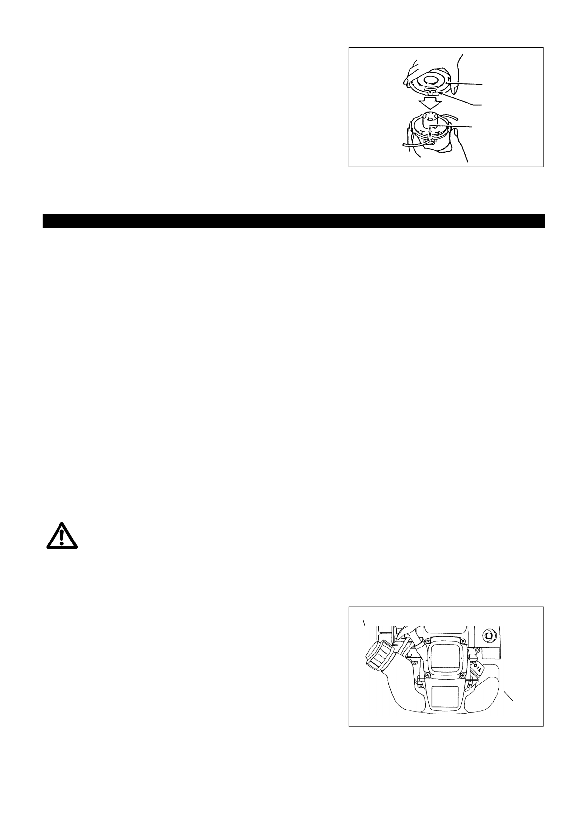
CLEANING OF AIR CLEANER
DANGER: INFLAM MABLES STRICTLY PROHIBITED
Interval of Cleaning and Inspection: Daily (every 10 operating hours)
– Turn the choke lever to the full close side, and keep the carburetor off from
dust or dirt.
– Remove the air cleaner cover-fixing bolts.
– Pull the cover lower side and detach the air cleaner cover.
– If oil adheres to the element (sponge), squeeze it firmly.
– For heavy contamination:
1) Remove the element (sponge), immerse it in warm water or in water-diluted
neutral detergent, and dry it completely.
2) Clean the element (felt) with gasoline, and dry it completely.
– Before attaching the element, be sure to dry it completely. Insufficient drying
of the element may lead to difficult startup.
– Wipe out with waste cloth, oil adhering around the air cleaner cover and plate
breather.
– Immediately after cleaning is finished, attach the cleaner cover and tighten it
with fixing bolts. (In remounting, first place the upper claw, and then the lower
claw.)
Element (sponge)
Air cleaner cover
Fixing bolt
Plate
Breather Part
Element (felt)
Points in Handling Air Cleaner Element
– Clean the element several times a day, if excessive dust adheres to it.
– If operation continues with the element remaining not cleared of oil, oil in
the air cleaner may fall outside, resulting in oil contamination.
19
Pick this part and remove the element (felt).
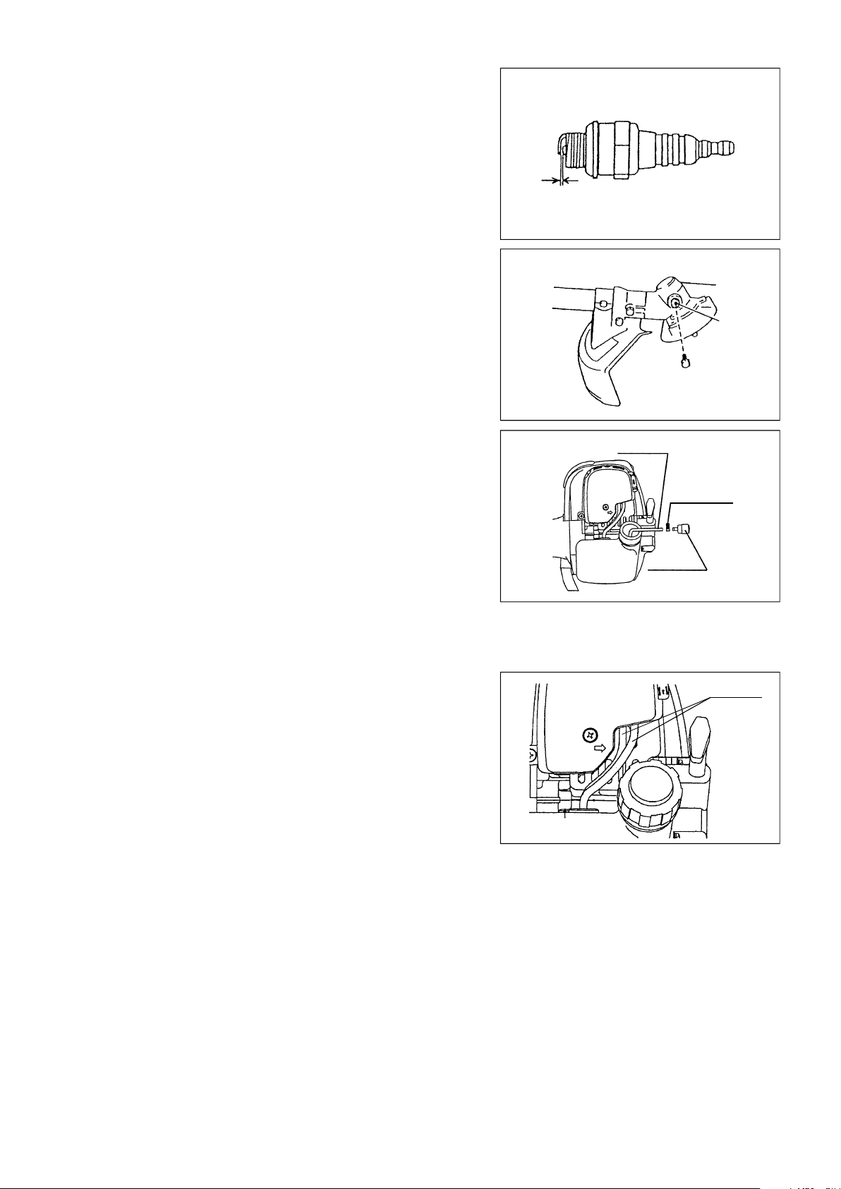
CHECKING THE SPARK PLUG
– Only use the supplied universal wrench to remove or to install the spark
plug.
– The gap between the two electrodes of the spark plug should be 0.7-0.8mm
(0.028”-0.032”). If the gap is too wide or too narrow, adjust it. If the spark
plug is clogged with carton or fouled, clean it thoroubhly or replace it.
CAUTION : Never touch the spark plug connector while the engine is running
(danger of high voltage electric shock).
SUPPLY OF GREASE TO GEAR CASE
– Supply grease (Shell Alvania 2 or equivalent) to the gear case through the
grease hole every 30 hours. (Genuine MAKITA grease may be purchased
from your MAKITA dealer.)
CLEANING OF FUEL FILTER
WARNING: INFLAMMABLES STRICTLY PROHIBITED
Interval of Cleaning and Inspection: Monthly (every 50 operating hours)
Suction head in the fuel tank
– The fuel filler (1) of the suction head is used to filler the fuel required by the
carburetor.
– A periodical visual inspection of the fuel filter is to be conducted. For that
purpose open the tank cap, use a wire hook and pull out the suction head
through the tank opening. Filters found to have hardened, been polluted or
clogged up are to be replaced.
– Insufficient fuel supply can result in the admissible maximum speed being
exceeded. It is therefore important to replace the fuel filter at least quarterly
to ensure satisfactory fuel supply to the carburetor.
0.7mm-0.8mm
(0.028”-0.032”)
Fuel pipe
House clamp
Fuel
filter(1)
Gear case
Grease hole
REPLACEMENT OF FUEL PIPE
Fuel pipe
CAUTION: INFLAMMABLES STRICTLY PROHIBITED
Interval of Cleaning and Inspection: Daily (every 10 operating hours)
Replacement: Annually (every 200 operating hours)
Replace the fuel pipe every year, regardless of operating frequency. Fuel
leakage may lead to fire.
If any leakage is detected during inspection, replace the oil pipe immediately.
INSPECTION OF BOLTS, NUTS AND SCREWS
– Retighten loose bolts, nuts, etc.
– Check for fuel and oil leakage.
– Replace damaged parts with new ones for safety operation.
CLEANING OF PARTS
– Keep the engine always clean.
– Keep the cylinder fins free of dust or dirt. Dust or dirt adhering to the fins will
cause seizure.
REPLACEMENT OF GASKETS AND PACKINGS
In reassembling after the engine is dismounted, be sure to replace the gaskets and packings with new ones.
Any maintenance of adjustment work that is not included and described in this manual is only to be performed by Authorized Service Agents.
20
STORAGE
WARNING: When draining the fuel, be sure to stop the engine and confirm that the engine cools
down.
Just after stopping the engine, it may still hot with possibility of burns, inflammability and fire.
ATTENTION: When the machine is kept out of operation for a long time, drain up all fuel from the
fuel tank and carburetor, and keep it at a dry and clean place.
– Drain up fuel from the fuel tank and carburetor according to the following
procedure:
1) Remove the fuel tank cap, and drain fuel completely.
If there is any foreign matter remaining in the fuel tank, remove it
completely.
2) Pull out the fuel filter from the refill port using a wire.
3) Push the primer pump until fuel is drained from there, and drain fuel
coming into the fuel tank.
4) Reset the filter to the fuel tank, and securely tighten the fuel tank cap.
5) Then, continue to operate the engine until it stops.
– Remove the spark plug, and drip several drops of engine oil through the
spark plug hole.
– Gently pull the starter handle so that engine oil will spread over the engine,
and attach the spark plug.
– Attach the cover to the cutter blade.
– During storage, keep the rod horizontal or keep the machine upright with the
blade edge oriented upward. (In this case, pay full attention to prevent the
machine from falling.)
Never store the machine with the cutter blade edge oriented downward.
Lubricating oil may spill out.
– Keep the drained fuel in a special container in a well-ventilated shade.
Drain fuel
Humidity
Attention after long-time storage
– Before startup after long-time shutdown, be sure to replace oil (refer to P 18). Oil will deteriorate while the machine is kept out of
operation.
Fault location
Fault System Observation Cause
Engine not starting or with
difficulty
No ignition spark
Fuel supply Fuel tank filled
Compression
Mechanical fault Starter not engaging Broken starter spring, broken parts inside of the engine
Warm start problems
Engine starts but dies Fuel supply Tank filled Incorrect idling adjustment, carburetor contaminated
Ignition system Ignition spark O.K.
No compression when
pulled over
Tank filled ignition spark
existing
Fault in fuel supply or compression system, mechanical
defect
STOP-switch operated, wiring fault or short circuit, spark
plug or connector defective, ignition module faulty
Incorrect choke position, carburetor defective, fuel supply
line bent or blocked, fuel dirty.
Cylinder bottom gasket defective, crankshaft seals
damaged, cylinder or piston rings defective or improper
sealing of spark plug
Carburetor contaminated, have it cleaned
Fuel tank vent defective, fuel supply line interrupted,
cable or STOP-switch faulty
Insufficient performance
Several systems
may simultaneously
be affected
Engine idling poor
21
Air filter contaminated, carburetor contaminated, muffler
clogged, exhaust duct in the cylinder clogged

Operating time
Item
Engine oil
Tightening parts
(bolt, nut)
Before
operation
After
lubrication
Daily
(10h)
30h 50h 200h
Shutdown
/rest
Corres-
ponding P
Inspect/clean ٤ 12
*1
Replace ٤
18
Inspect ٤ 20
Fuel tank
Drain fuel ٤
*3
21
Throttle lever Check function ٤ 14
Stop switch Check function ٤ 14
Cutting blade Inspect ٤ ٤ 10
Low-speed rotation Inspect/adjust ٤ 16
Air cleaner Clean ٤ 19
Ignition plug Inspect ٤ 20
Cooling air duct Clean/inspect ٤ 20
Inspect ٤ 20
Clean/inspect ٤
Fuel pipe
Replace ٧
Gear-case grease Refill
20
٤
*2
Fuel filter Clean/replace ٤ 20
Clearance between air intake
valve and air discharge valve
Adjust ٧
*2
Engine overhaul ٧*2
Carburetor Drain fuel ٤*3 21
*1 Perform initial replacement after 20h operation.
*2 For the 200 operating hour inspection, request Authorized Service Agent or a machine shop.
*3 After emptying the fuel tank, continue to run the engine and drain fuel in the carburetor.
22

TROUBLESHOOTING
Before making a request for repairs, check a trouble for yourself. If any abnormality is found, control your machine according to the
description of this manual. Never tamper or dismount any part contrary to the description. For repairs, contact Authorized Service Agent or
local dealership.
State of abnormality Probable cause (malfunction) Remedy
Failure to operate primer pump Push 7 to 10 times.
Low pulling speed of starter rope Pull strongly.
Lack of fuel Feed fuel.
Clogged fuel filter Clean
Broken fuel tube Straighten fuel tube
Engine does not start
Engine stops soon
Engine speed does not increase
Cutter blade does not rotate
Stop engine immediately㩷
Deteriorated fuel
Excessive suction of fuel
Detached plug cap Attach securely
Contaminated spark plug Clean
Abnormal clearance of spark plug Adjust clearance
Other abnormality of spark plug Replace
Abnormal carburetor Make request for inspection and maintenance.
Starter rope cannot be pulled Make request for inspection and maintenance
Abnormal drive system Make request for inspection and maintenance
Insufficient warm-up Perform warm-up operation
Choke lever is set to “CLOSE” although engine
is warmed up
Clogged fuel filter Clean
Contaminated or clogged air cleaner Clean
Abnormal carburetor Make request for inspection and maintenance
Abnormal drive system Make request for inspection and maintenance
Loosened cutter blade-tightening nut Tighten securely
Twigs caught by cutter blade or
dispersion-preventing cover
Abnormal drive system Make request for inspection and maintenance.
Deteriorated fuel makes starting more difficult.
Replace with new one. (Recommended
replacement: 1 month)
Set throttle lever from medium speed to high
speed, and pull starter handle until engine
starts. Once engine starts, cutter blade
starts rotating. Pay full attention to cutter
blade.
If engine will not start still, remove spark plug,
make electrode dry, and reassemble them as
they originally are. Then, start as specified.
Set to “OPEN”
Remove foreign matter
Main unit vibrates abnormally.
Stop engine immediately㩷
Cutter blade does not stop immediately.
Stop engine immediately㩷
Engine does not stop.
Run engine at idling, and set choke
lever to CLOSE.
When the engine does not start after warm-up operation:
If there is no abnormality found for the check items, open the throttle by about 1/3 and start the engine.
㩷
Broken, bent or worn cutter blade Replace cutter blade
Loosened cutter blade-tightening nut Tighten securely
Shifted convex part of cutter blade and cutter
blade support fitting
Abnormal drive system Make request for inspection and maintenance
High idling rotation Adjust
Detached throttle wire Attach securely
Abnormal drive system Make request for inspection and maintenance
Detached connector Attach securely
Abnormal electric system Make request for inspection and maintenance.
Attach securely
23

EMISSION COMPLIANCE PERIOD
For handheld engine : The Emissions
Compliance Period referred to on the Emissions
Compliance label indicates the number of operating hours for which the engine
has been shown to meet Federal emission requirements.
Category C=50 hours, B=125 hours, and A=300 hours.
AIR INDEX
An Air Index Information hang tag was supplied to this engine in accordance with the
emission regulations of the California Air Resources Board.
The bar graph on the hang tag shows the emissions performance of this engine.
The bar graph can be used to compare the emissions performance with other available
engine. The lower the Air Index, the less pollution.
The following durability description is to provide you with information relating to the
emission durability period of the engine.
Descriptive Term Applicable to Emissions Durability Period
Moderate − 50hours (0-65 cc)
Intermediate − 125hours (0-65cc)
Extended − 300hours (0-65cc)
Notice : The Air Index Information hang tag must remain on the engine or on the
equipment until it is sold to the ultimate purchaser. Remove the hang tag
before operating the engine.
24

CALIFORNIA EMISSIONS CONTROL WARRANTY STATEMENT
YOUR WARRANTY RIGHTS AND OBLIGATIONS
The California Air Resources Board and Makita USA, Inc are pleased to explain the emissions
control system’s warranty on your 2007 and later small off-road engine. In California, new
equipment that use small off-engines must be designed, built, and equipped to meet the State’s
stringent anti-smog standards. Makita USA, Inc must warrant the emissions control system on
your small off-road engine for the period listed below provided there has been no abuse, neglect
or improper maintenance of your equipment.
Your emissions control system may include parts such as: carburetors or fuel injection system,
ignition system, catalytic converters, fuel tanks, valves, filters, clamps, connectors, and other
associated components. Also, included may be hoses, belts, connectors, sensors, and other
emission-related assemblies.
Where a warrantable condition exists, Makita USA, Inc will repair your small off-road engine at
no cost to yo u including diagnosis, parts and labor.
MANUFACTURER’S WARRANTY COVERAGE:
This emissions control system is warranted for two years. If any emissions-related part on your
equipment is defective, the part will be repaired or replaced by Makita USA, Inc .
OWNER’S WARRANTY RESPONSIBILITIES:
§ As the small off-road engine owner, you are responsible for performance of the required
maintenance listed in your owner’s manual. Makita USA, Inc recommends that you retain all
receipts covering maintenance on your small off-road engine, but Makita USA, Inc cannot
deny warranty solely for the lack of receipts or your failure to ensure the performance of all
scheduled maintenance.
§ As the small off-road engine owner, you should however be aware that Makita USA, Inc may
deny you warranty coverage if your small off-road engine or a part has failed due to abuse,
neglect, or improper maintenance or unapproved modifications.
§ You are responsible for presenting your small off-road engine to a Makita Factory Service
Center as soon as the problem exists. The warranty repairs should be completed in a
reasonable amount of time, not to exceed 30 days. If you have a question regarding your
warranty coverage, you should contact :
* For the nearest Makita service center, please visit www.makitatools.com
* For technical support or questions regarding operation of our tools and accessories
call: 1-800-4- MAKITA
* Makita USA Inc. Corporate Office: 14930 Northam St. La Mirada, CA 90638-5753
DEFECTS WARRANTY REQUIREMENTS:
(a) The warranty period begins on the date the engine or equipment is delivered to an ultimate
purchaser.
(b) General Emissions Warranty Coverage. Makita USA, Inc must warrant to the ultimate
purchaser and each subsequent owner that the engine or equipment is:
(1) Designed, built, and equipped so as to conform with all applicable regulations adopted
by the Air Resources Board; and
(2) Free from defects in materials and workmanship that causes the failure of a warranted
part for a period of two years.
(c) The warranty on emissions-related parts will be interpreted as follows:
25

(1) Any warranted part that is not scheduled for replacement as required maintenance in
the written instructions required by subsection (d) must be warranted for the warranty
period defined in Subsection (b)(2). If any such part fails during the period of
warranty coverage, it must be repaired or replaced by the manufacturer according to
Subsection (4) below. Any such part repaired or replaced under the warranty must
be warranted for the remaining warranty period.
(2) Any warranted part that is scheduled only for regular inspection in the written
instructions required by subsection (d) must be warranted for the warranty period
defined in Subsection (b)(2). A statement in such written instructions to the effect of
“repair or replace as necessary” will not reduce the period of warranty coverage. Any
such part repaired or replaced under warranty must be warranted for the remaining
warranty period.
(3) Any warranted part that is scheduled for replacement as required maintenance in the
written instructions required by subsection (d) must be warranted for the period of time
prior to the first scheduled replacement point for that part. If the part fails prior to the
first scheduled replacement, the part must be repaired or replaced by the engine
manufacturer according to Subsection (4) below. Any such part repaired or replaced
under warranty must be warranted for the remainder of the period prior to the first
scheduled replacement point for the part.
(4) Repair or replacement of any warranted part under the warranty must be performed at
no charge to the owner at a warranty station.
(5) Notwithstanding the provisions of Subsection (4) above, warranty services or repairs
must be provided at all manufacturer distribution centers that are franchised to service
the subject engines.
(6) The owner must not be charged for diagnostic labor that leads to the determination
that a w arranted part is in fact defective, provided that such diagnostic work is
performed at a warranty station.
(7) The manufacturer is liable for damages to other engine components proximately
caused by a failure under warranty of any warranted part.
(8) Throughout the emissions warranty period defined in Subsection (b)(2), the
manufacturer must maintain a supply of warranted parts sufficient to meet the
expected demand for such parts.
(9) Any replacement part may be used in the performance of any warranty maintenance
or repairs and must be provided without charge to the owner. Such use will not
reduce the warranty obligations of the manufacturer.
(10) Add-on or modified parts that are not exempted by the Air Resources Board may not
be used. The use of any non-exempted add-on or modified parts will be grounds for
disallowing a warranty claim. The manufacturer will not be liable to warrant failures
of warranted parts caused by the use of a non-exempted add- on or modified part.
(11) The manufacturer issuing the warranty shall provide any documents that describe that
manufacturer's warranty procedures or policies within five working days of request by
the Air Resources Board.
(d) Emission Warranty Parts List.
(1) Fuel Metering System
(i) Carburetor and internal parts
(ii) Fuel Filter
(iii) Fuel Tank.
(2) Air Induction System
(i) Air cleaner plate (including choke system)
(ii) Air cleaner cover
(iii) Air cleaner element
26

(3) Ignition System
(i) Spark Plugs.
(ii) Magneto or electronic ignition system.
(iii) Spark advance/retard system.
(4) Miscellaneous Items Used in Above Systems
(i) Hoses, Sealing gaskets, belts, connectors, and assemblies.
Makita USA, Inc will furnish with each new engine written instructions for the maintenance and
use of the engine by the owner.
(e) MAINTENANCE STATEMENTS
It is your responsibility to have all scheduled inspection an d maintenance services performed
at the times recommended in the 2007 and later Owner's Manual and to retain proof that
inspection and maintenance services are performed at the times when recommended. Makita
USA, Inc will not deny a warranty claim solely because you have no record of maintenance;
however, Makita USA, Inc may deny a warranty claim if your failure to perform required
maintenance resulted in the failure of warranted part. The proof, which you maintain, should
be given to each subsequent owner of the engine. You are responsible for performing the
scheduled maintenance described below based on the procedures specified in the 2007 and
later Owner's Manual. The scheduled maintenance below is based on the normal
engine- operating schedule.
PROCEDURE INTERVAL
1) Clean engine and check bolts and nuts.
:Every 8 hours(daily)
Retighten if necessary.
2) Check and refill engine oil (4stroke
:Every 8 hours(refill daily up to upper limit)
engine only)
3) Change engine oil (4stroke engine only) :Initial 20 hours an d every 50 hours
afterward
4) Check clogging of cooling air passage
:Every 8 hours (daily)
and cylinder fins. Remove and clean if
necessary.
5) Clean air cleaner. :Every 8 hours (daily)
6) Check spark plug. Clean and adjust if
:Every 8 hours (daily)
necessary.
7) Check muffler exhaust outlet(or port).
:Every 50 hours (monthly)
Clean if necessary.
8) Check fuel filter. If clogged, replace with
:Every 50 hours (monthly)
new one.
9) Adjust valve clearance, if applicable
:Every 200 hours (yearly)
(4stroke engine only).
10) Replace fuel lines. :Every 200 hours (yearly)
11) Clean and inspect the complete engine.
:Every 200 hours
Replace any damaged or worn out parts.
12) Replace packings and gaskets with new
:Every reassembling
ones.
27

FEDERAL EMISSION COMPONENT DEFECT WARRANTY
EMISSION COMPONENT DEFECT WARRANTY COVERAGE - This emission warranty is applicable in all
States, except the State of California
Makita U.S.A., Inc., (herein "Makita") warrant to the initial retail purchaser and each subsequent owner,
that this utility equipment engine (herein "engine") was designed, built, and equipped to conform at the time
of initial sale to all applicable regulations of the U.S. Environmental Protection Agency (EPA), and that the
engine is free of defects in materials and workmanship which would cause this engine to fall to conform with
EPA regulations during its warranty period.
For the components listed under PARTS COVERED, the dealer or service center authorized by Makita will,
at no cost to you, make the necessary diagnosis, repair, or replacement necessary to ensure that the engine
complies with applicable U.S. EPA regulations.
EMISSION COMPONENT DEFECT WARRANTY PERIOD
The warranty period for this engine begins on the date of sale to the initial purchaser and continues for a
period of 2 years.
PARTS COVERED
Listed below are the parts covered by the Emission Component Defect Warranty. Some of the parts listed
below may require scheduled maintenance and are warranted up to the first scheduled replacement point for
that part.
1) Fuel Metering System
(i) Carburetor and internal parts
(ii) Fuel filter, if applicable
(iii) Throttle stopper, if applicable
(iv) Choke System, if applicable
2) Air Indu ction System
(i) Air cleaner plate
(ii) Air cleaner case
3) Ignition System
(i) Spark plug
(ii) Flywheel Magneto
(iii) Ignition Coil
4) Miscellaneous Items Used in Above Systems
(i) Fuel hoses, clamps and sealing gaskets
(iii) Air cleaner element
5) Emission-related components for evaporative emission
(i) Fuel Tank
(ii) Fuel Cap
(iii) Fuel line
(iv) Fuel line fitting
(v) Clamps
28

OBTAINING WARRANTY SERVICE
To obtain warranty service, take your engine to the nearest MAKITA Factory Service Center authorized
by MAKITA. Bring your sales receipts indicating date of purchase for this engine. The dealer or service
center authorized by Makita will perform the necessary repairs or adjustments within a reasonable amount
of time and furnish you with a copy of the repair order. All parts and accessories replaced under this
warranty become the property of Makita.
WHAT IS NOT COVERED
* Conditions resulting from tampering, misuse, improper adjustment (unless they were made by the dealer or
service center authorized by Makita during a warranty repair), alteration, accident, failure to use the
recommended fuel and oil, or not performing required maintenance services.
* The replacement parts used for required maintenance services.
* Consequential damages such as loss of time, inconvenience, loss of use of the engine of equipment, etc.
* Diagnosis and inspection charges that do not result in warranty-eligible service being performed.
* Any non-authorized replacement part, or malfunction of authorized parts due to use of non-authorized
parts.
OWNER'S WARRANTY RESPONSIBILITIES
As the engine owner, you are responsible for the performance of the required maintenance listed in your
owner's manual, Makita recommends that you retain all receipt s covering maintenance on your engine, but
Makita can not deny warranty solely for the lack of receipts or for your failure to ensure the performance of
all scheduled maintenance.
As the engine owner, you should however be aware that the Makita may deny your warranty coverage if
your engine or a part has failed due to abuse, neglect, improper maintenance or unapproved modifications.
You are responsible for presenting your engine to the nearest dealer or service center authorized by
Makita when a problem exists.
If you have any questions regarding your warranty rights and responsibilities, you should contact the
Followings:
* For the nearest Makita service center, please visit www.makitatools.com
* For technical support or questions regarding operation of our tools and accessories call: 1-800-4-MAKITA
* Makita USA Inc. Corporate Office: 14930 Northam St. La Mirada, CA 90638 -5753
(For Canada)
*For the authorized service center nearest you please refer to the local yellow pages directory under “tools”,
or contact our customer service department Tel 1-800-263-3734(Canada only), or visit our web site
www.makita.ca
*Makita Canada Inc. Head Office & Plant: 1950 Forbes Street, Whitby, ON L1N7B7
.
29

THINGS YOU SHOULD KNOW ABOUT THE EMISSION CONTROL SYSTEM WARRANTY
MAINTENANCE AND REPAIRS
You are responsible for the proper use and maintenance of the engine. You should keep all receipts and
maintenance records covering the performance of regular maintenance in the event questions arise. These
receipts and maintenance records should be transferred to each subsequent owner of the engine. Makita
reserves the rights to deny warranty coverage if the engine has not been properly maintained. Warranty
claims will not be denied, however, solely because of the lack of required maintenance or failure to keep
maintenance records.
MAINTENANCE, REPLACEMENT OR REPAIR OF EMISSION CONTROL DEVICES AND
SYSTEMS MAY BE PERFORMED BY ANY REPAIR ESTABLISHMENT OR INDIVIDUAL;
HOWEVER, WARRANTY REPAIRS MUST BE PERFORMED BY A DEALER OR SERVICE
CENTER AUTHORIZED BY Makita. THE USE OF PARTS THAT ARE NOT EQUIVALENT IN
PERFORMANCE AND DURABILITY TO AUTHORIZED PARTS MAY IMPAIR THE
EFFECTIVENESS OF THE EMISSION CONTROL SYSTEM AND MAY HAVE A BEARING ON
THE OUTCOME OF A WARRANTY CLAIM.
If other than the parts authorized by Makita are used for maintenance replacements or for the repair of
components affecting emission control, you should assure yourself that such parts are warranted by their
manufacturer to be equivalent to the parts authorized by Makita in their performance and durability.
HOW TO MAKE A CLAIM
All repairs qualifying under this limited warranty must be performed by a service dealer authorized by
MAKITA . In the event that any emission-related part is found to be defective during the warranty period, you
shall notify MAKITA at the following contacts and you will be advised of the appropriate warranty
service dealer or service providers where the warrant y repair can be performed.
* For the nearest Makita service center, please visit www.makitatools.com
* For technical support or questions regarding operation of our tools and accessories call: 1-800-4-MAKITA
* Makita USA Inc. Corporate Office: 14930 Northam St. La Mirada, CA 90638 -5753
(For Canada)
*For the authorized service center nearest you please refer to the local yellow pages directory under “tools”,
or contact our customer service department Tel 1-800-263-3734(Canada only), or visit our web site
www.makita.ca
*Makita Canada Inc. Head Office & Plant: 1950 Forbes Street, Whitby, ON L1N7B7.
30

Français
Nous vous remercions d’avoir fait l’acquisition de la débroussailleuse / taillebordures MAKITA. Nous sommes heureux de pouvoir vous conseiller la
débroussailleuse / taille-bordures MAKITA qui représente le résultat d’un long
programme de développement et de plusieurs années de recherche et
d’expérience.
Veuillez lire cette brochure qui fait référence en détail aux différents points
témoignant de l’efficacité exceptionnelle de votre débroussaileuse MAKITA.
SYMBOLES
Vous rencontrerez les symboles suivants en parcourant le manuel d'instructions.
Lire le manuel d’instructions
Table des matières Page
Symboles .................................................................. 31
Consignes de sécurité .............................................. 32
Caractéristiques techniques ..................................... 36
Nomenclature des pièces ......................................... 37
Montage de la poignée .............................................. 38
Montage du dispositif de protection .......................... 39
Montage de la lame de coupe ou de la tête
de coupe à fil ............................................................ 40
Avant mise en marche .............................................. 41
Manipulation correct de la machine .......................... 43
Consignes de mise en marche et arrêt de la machine43
Réaffûtage de l'outil de coupe .................................. 45
Instructions relatives aux réparations ...................... 47
Remisage .................................................................. 50
Porter des protections visuelles et
auditives(pour la taille bordures
d’herbe)
Etre particuliérement soigneux et
attentif
Interdit
Maintenir ses distances
Risque de projections d’objets
Interdit de fumer
Pas de flamme une
Porter un casque de protection, des
protections visuelles et auditives(pour
la debroussailleuse uniquement)
Ne pas utiliser de lames métalliques
(Pour la taille bordures uniquement)
Vitesse maximale carburant et d’huile
Carburant (Essence)
Démarrage manuel de la machine
Arrêt d’urgence
Premier secours
Porter des gants de protection
Rejet
Maintenir toute personne et tout
animai domestique à l’écart de la zone
de travail
31
I
O
Recyclage
On/Démarrage
Off/Arrêt

CONSIGNES DE SÉCURITÉ
Instructions générales
– Pour utiliser la machine correctement, I’utilisateur doit lire ce manuel
d’instructions afin de se familiariser avec la manipulation de la
débroussailleuse / taille-bordures. Les utilisateurs disposant d’informations
insuffisantes risquent de mettre leur propre vie comme celle de tiers en
danger en manipulant la machine de façon incorrecte.
– Il est conseillé de prêter la débroussailleuse / taille-bordures uniquement à
des personnes ayant fait leurs preuves dans la manipulation de
débroussailleuse / taille-bordures.
Toujours leur remettre le manuel d’instructions.
– Les premiers utilisateurs devraient demander au concessionnaire de leur
dispenser les instructions de base afin de se familiariser à la manipulation de
débroussailleuse / taille-bordures thermique.
– Les enfants et les jeunes gens de moins de 18 ans ne sont pas autorisés à
utiliser la débroussailleuse / taille-bordures. Cependant, les jeunes gens
âgés de plus de 16 ans peuvent utiliser la machine pour s'entraîner, mais
uniquement sous la surveillance d'un formateur qualifié.
– Utiliser les débroussailleuse / taille-bordures avec le plus de soin et
d'attention possibles.
– Utilisez la débroussailleuse / taille-bordures uniquement si vous être en
bonne condition physique.
Procédez aux travaux avec calme et attention. L’utilisateur est responsible
vis à vis des autres personnes.
– Ne jamais utiliser la débroussailleuse / taille-bordures après absorption
d'alcool ou de médicaments ou si l'on se sent fatigué ou souffrant.
Utilisation spéciale de la machine
– La débroussailleuse / taille-bordures est seulement pour couper l’herbes,
broussailles et en sous-bois. Ne jamais employer la machine pour les
usages comprenant tailles de bordure et de haies que pouvaient causer des
blessures.
Équipement personnel de protection
– Les habits doivent être fonctionnels et adaptés, c'est-à-dire qu'ils doivent être
serrés sans toutefois entraver les mouvements. Ne pas porter de bijoux ou
d'habits qui pourraient s'accrocher dans les buissons ou les broussailles.
– Porter l'équipement et les habits de protection lors de l'utilisation de la
débroussailleuse / taille-bordures afin d'éviter les blessures au niveau de la
tête, des yeux, des mains ou des pieds.
– Toujours porter un casque dans les endroits o'les chutes d'objets sont
possibles. Vérifier à intervalles réguliers si le casque de protection (1) n'est
pas endommagé et le remplacer au plus tard aprés 5 ans. Utiliser
uniquement des casques de protection réglementaires.
– La visière (2) du casque (ou les lunettes) protège le visage des débris et des
pierres projetées. Toujours porter des lunettes ou une visière pour éviter les
blessures au niveau des yeux lors de l'utilisation de la débroussailleuse /
taille-bordures.
– Porter un équipement de protection contre le bruit approprié pour éviter une
détérioration de l'ouïe (serre-tête (3), protège-tympans etc.).
– La combinaison de travail (4) protège contre les projections de débris et de
pierres. Nous conseillons vivement à l'utilisateur d’en porter une.
– Des gants spéciaux (5) en cuir épais font partie de l'équipement prescrit et
doivent être portés en permanence lors de l'utilisation de la débroussailleuse
/ taille-bordures.
– Lors de l'utilisation de la débroussailleuse / taille-bordures, toujours porter
des chaussures de sécurité (6) munies d'une semelle antidérapante. Elles
assurentt une protection contre les blessures et un bon équilibre.
Démarrage de la débroussailleuse
– Veuillez vous assurer de l'absence d'enfants ou d'autres personnes dans un
rayon de 15 mètres ainsi que d'animaux à proximité de la zone de travail.
– Avant d'utiliser la machine, toujours vérifier que la débroussailleuse /
taille-bordures peut fonctionner en toute sécurité.
Vérifier si l'outil de coupe est en bon état, si le levier de commande peut être
actionné facilement et si le verrou du levier de commande fonctionne
correctement.
En cas de doute, consulter son revendeur pour les réglages. Au ralenti la
tête de coupe ne doit pas tourner. Vérifier si les poignées sont propres et
sèches et tester le fonctionnement de l’interrupteur de marche/arrêt.
Diagrammatic figure
15mètres
32

– Mettre la débroussailleuse / taille-bordures en marche en appliquant
strictement les instructions.
Ne pas utiliser d’autres méthodes pour mettre la machine en marche!
– Utiliser la débroussailleuse / taille-bordures et les outils uniquement pour les
applications conseillées.
– Lancer le moteur de la débroussailleuse / taille-bordures uniquement une fois
le montage intégralement réalisé. Il est interdit d'utiliser la machine avant
que les accessoires appropriés ne soient montés
– Avant de mettre la machine en marche, s'assurer que l'outil de coupe n'est
pas en contact avec des objets durs tels que des branches ou des pierres car
la lame de coupe tournera au démarrage.
– Couper immédiatement le moteur en cas ou problémes.
– Si la lame de coupe devait heurter des pierres ou d'autres objets durs, couper
immédiatement le moteur et inspecter la lame de coupe.
– Vérifier à intervalles réguliers que l'outil de coupe n'est pas endommagé
(détection de fêlures en sonnant l'outil).
– Utiliser la débroussailleuse / taille-bordures uniquement lorsque le harnais est
fixé sur l'épaule; ce harnais doit être ajusté correctement avant de mettre la
machine en marche. Le harnais doit être ajusté en fonction de la taille de
l'utilisateur afin d'éviter qu'il ne se fatigue. Ne jamais tenir la
débroussailleuse / taille-bordures avec une seule main lors du
fonctionnement.
– Toujours tenir la débroussailleuse / taille-bordures avec les deux mains lors
du fonctionnement.
Toujours garantir une bonne stabilité.
– Utiliser la débroussailleuse / taille-bordures de manière á éviter l'inhalation de
gaz d'échappement. Ne jamais utiliser la machine dans des espaces clos
(risque d'intoxication au gaz). Le monoxyde de carbone est un gaz inodore.
– Coupez le moteur lors des pauses et lorsque vous laissez la débroussailleuse
/ taille-bordures sans surveillance et la placer dans un lieu sûr afin d'éviter de
mettre la vie de tiers en danger ou d'endommager la machine.
– Ne jamais placer la débroussailleuse / taille-bordures encore chaude sur de
l'herbe sèche ou sur tout autre matériau combustible.
– L'outil de coupe doit être équipé de la protection appropriée. Ne jamais
utiliser la débroussailleuse / taille-bordures sans cette protection!
– Utiliser tous les dispositifs de protection fournis avec la machine.
– Ne jamais lancer la moteur si le pot d'échappement est défectueux.
– Couper le moteur lors du transport.
– Toujours utiliser la protection de l'outil incluse dans l'équipement pour le
transport sur de longues distances.
– S'assurer du positionnement correct de la débroussailleuse / taille-bordures
afin d'éviter des fuites d'huile.
– Vérifier que le réservoir de carburant est complètement vide lors du transport
de la débroussailleuse / taille-bordures.
– Lors du déchargement de la débroussailluse/ taille-bordures ne jamais la
laissez tomber sur le sol pour éviter des dommage important sur le réservoir
d’essence.
– Sauf cas d’urgence, ne jamais laisser tomber ou lancer le débroussailleuse /
taille-bordures sur le sol, cela endommagera débroussailleuse /
taille-bordures.
– Ne jamais trainer l’appareil pour le déplacer. Toujours le déplacer en le
soulevant par le bas. Si l’appareil traîne sur le sol le réservoir à combustible
peut être endommagé, le combustible risque de se renverser et provoquer un
début d’incendie.
㩷
Ravitaillement
– Couper le moteur durant le ravitaillement, se tenir à l'écart des flammes et ne
pas fumer.
– Éviter les contacts cutanés avec des produits à base d'huile minérale. Ne
pas respirer des vapeurs de carburant. Toujours porter des gants de
protection lors du ravitaillement. Changer et nettoyer les habits de protection
à intervalles réguliers.
– Prendre garde à ne pas renverser du carburant ou de l'huile afin d'éviter de
polluer le sol (protection de l'environnement). Nettoyer immédiatement la
débroussailleuse / taille-bordures après débordement de carburant.
– Évitez tout contact entre le carburant et les habits. Si du carburant a été
renversé sur vos habits, changez-en imm'ediatement pour éviter que les
habits ne prennent feu.
– Inspecter le bouchon du réservoir à intervallles réguliers en vérifiant s’il est
serré correctement et qu’il n'y a pas de fuite.
– Serrer soigneusement le bouchon du réservoir du carburant. Changer
d'endroit pour lancer le moteur (au moins à trois mètres de l'emplacement de
ravitaillement).
– Ne jamais procéder au ravitaillement dans des espaces clos. Les vapeurs
de carbutant s'accumulent au niveau du sol (risque d'explosions).
– Transporter et stocker le carburant uniquement dans des containers
réglementaires. S'assurer que le carburant stocké n'est pas accessible aux
enfants.
• Repos
• Transport
• Ravitaillement
• Maintenance
• Changement d’outils
3 mètres
33

Méthode d'utilisation
– Utiliser la débroussailleuse / taille-bordures uniguement lorsque les conditions
de luminosité et de visibilité sont bonnes. En hiver, être conscient des
risques engendrés par le verglas, les zones humides, la glace et la neige
(dérapage). Toujours garantir une bonnes stabilité.
– Ne jamais couper au-dessus de la hauteur de la taille.
– Ne jamais se tenir sur une échelle en manipulant la débroussailleuse /
taille-bordures.
– Ne jamais grimper dans les arbres pour procéder à des travaux de coupe
avec la débroussailleuse / taille-bordures.
– Ne jamais travailler sur des surfaces instables.
– Retirer le sable, les pierres, les clous etc. trouvés à l'intérieur du rayon
d'action. Les particules étrangères risquent d'endommager la lame de coupe
et peuvent engendrer des projection dangereuse.
– Attendre que la lame ait atteint sa pleine vitesse de travail avant de
commencer à couper.
㩷
Effet de retour
– Un retour incontrôlé peut se produire lors de l'utilisation de la
débroussailleuse.
– Ce phénomène se produit en particulier lors de coupes effectuées dans
l'angle de lame compris entre midi et 2 h.
– Ne jamais utiliser la débroussailleuse dans I'angle de la lame compris entre
midi et 2 h
– Ne jamais utiliser un tel angle de la lame pour la coupe de matériaux solides
tels buissons, arbres etc. dont le diamètre est supérieur à 3 cm car la
débroussailleuse scrait alors déviée avec une force importante et pourrait
ainsi provoquer des blessures.
Attention:Retour
Représentation
schématique
㩷
㩷
Prévention contre l’effet de retour
Observer les points suivants pour éviter l’effet de retour:
– Le mode de fonctionnement "Angle de lame entre midi et 2 h" présente
certaines risques, en particulier lors de l'utilisation d'outils de coupe
métalliques.
– Seuls des utilisateurs formés et expérimentés peuvent procéder à des travaux
de coupe avec des angles de lame compris entre 11 et midi ou 2 et 5 h, et ce
uniquement à leurs propres risques. Une coupe facile et quasiment exempte
de retour peut s’effectuer à un angle compris entre 8 et 11 h.
㩷
㩷
Outils de coupe
Utiliser uniquement les outils de coupe corrects pour procéder aux fravaux.
Lame de coupe en métal:
Lame de coupe (lame Star à 4 dents, lame Eddy à 8 dents), Tête de coupe à fil
Pour couper les matériaux épais, comme les mauvaises herbes, hautes herbes,
buissons, l arbustes, sous-bois, fourrés, etc. (diamètre maximal de 2 cm). Pour
ce genre de travaux, déplacer la débroussailleuse en demi-cercles réguliers, de
droite à gauche (comme avec une faux).
Instructions de maintenance
– L'état de la débroussailleuse / taille-bordures et en particulier l’outil de coupe,
des appareils de protection ainsi que de la courroie de maintien doivent être
vérifié avant le début des travaux. Attacher particulièrement de l'attention
aux lames de coupe qui doivent être affûtées correctement.
– Couper le moteur et retirer le connecteur de la bougie d'allumage lors de
mantage ou de l'affûtage des outils de coupe et également lors du nettoyage
de la débroussailleuse / taille-bordures ou de l'outil de coupe.
Représentation
schématique
34

Ne jamais redresser ou souder des outils de coupe endommages.
– Utiliser la débroussailleuse / taille-bordures à un niveau sonore et polluant
aussi faible que possible. Contrôler en particulier si le carburateur est monté
correctement.
– Nettoyer la débroussailleuse / taille-bordures à des intervalles réguliers et
vérifier que l'ensemble des vis et des écrous soient bien serrés
– Ne jamais réparer ou remiser la débroussailleuse / taille-bordures à proximité
de flammes.
– Toujours remiser la débroussailleuse / taille-bordures dans des pièces
fermées à clé et en veillant à ce que le réservoir de carburant soit vide.
Respecter les instructions de prévention contre les accidents établies par les
associations commerciales et les compagnies d'assurance habilitées.
Ne procéder à aucune modification sur la débroussailleuse / taille-bordures car
elles pourraient mettre votre vie en danger.
L'efficacité des travaux de maintenance et des réparations se limite aux opérations
décrites dans le manuel d'instructions.
Tout autre opération doit être effectuée par un agent habilité du service après-
vente.
Utiliser uniquement des piéces détachées et des accessoires d'origine
commercialisés et fournis par MAKITA.
L'utilisation d'accessoires et d'outils non autorisés peut accroître le risque
d'accidents.
MAKITA décline toute responsabilité pour des accidents ou des dommages
survenus à la suite de l'utilisation d'outils de coupe, d'appareils de fixation pour
outils de coupe et d'accessoires non autorisés.
Premier secours
Vérifier qu'une boîte de premier secours est toujours disponible à proximité du
lieu de travail. Remplacer immédiatement tout article prélevé dans la boîte de
premier secours.
Si vous demandez du secours, veuillez indiquer les informations
suivantes:
– Lieu de l'accident
– Ce qui se passe
– Le nombre de personnes blessées
– Le type de blessures
– Votre nom
Emballage
La débroussailleuse / taille-bordures MAKITA est livrée dans deux cartons
de protection afin d’éviter des endommagements au cours du transport.
Le carton est une matière première réutilisable ou recyclable (recyclage des
vieux papiers).
35

CARACTERISTIQUES TECHNIQUES EM4250/EM4250CA, EM4251/EM4251CA
EM4251/EM4251CA EM4250/EM4250CA
Modèle
Poignée Simple Poignée en U
Dimensions: longueur x largeur x hauteur
(sans lame de coupe) mm
1760x330x265 1760x600x405
Masse (sans protection en plastique et lame de coupe) kg 5.2 5.4
Volume (réservoir de carburant) L 0.5
Volume (réservoir d’huile) L 0.08
Oylindrée du moteur cc 24.5
Puissance maximale du moteur HP 0.885/7000 /min
Vitesse du moteur à la vitesse max. autorisée pour l'arbre /min 8500
Vitesse d'arbre maximale (correspondante) /min 6500
Consommation maxi de carburant kg/h 0.33
Consommation spécifique maxi de carburant g/HPh 304
Vitesse de rotation au ralenti /min 3000
Vitesse d'embrayage /min 3750
Carburateur type WALBRO WYL
Système d'injection type Type Allumage électronique
Bougie d'allumage type NGK CMR6A
Jeu électrodes mm 0.7 – 0.8
Ralenti m/s
Emballement ou régime maxi m/s
Ralenti m/s
Emballement ou régime maxi m/s
Vibration
selon
ISO 7916
Poignée droite
(prise arrière)
1)
Poignée gauche
(prise avant)
Moyenne du niveau de pression acoustique selon ISO 7917
Moyenne du niveau de puissance sonore selon ISO 10884
1)
1)
2
2
2
2
2.59 4.72
6.27 4.7
3.26 3.83
7.24 7.56
dB 87.7 87.7
dB 97.7 97.7
Carburant Essence pour moteur
Huile pour moteur
SAE 10W- 30 huile de la classification API, classe SF ou supérieure
(moteur à quatre temps pour automobile)
Rapport d'engrenage 14/19
36

NOMENCLATURE DES PIÈCES
ԛ
Ԣ
EM4250/EM4250CA
Débroussailleuses
ԥ
Ԩ
EM4251/EM4251CA
Taille-borduress
Ԧ
Ԥ
ԧ
ԡ
ԣ
ԡ
Ԡ
Ԡ
Ԣ
ԝ
ԟ
ԛ
Ԟ
Ԝ
Ԟ
ԣ
Ԙ
ԝ
Ԙ
Ԛ
ԫ
Ԝ
Ԛ
ԫ
F Nomenclature des pièces
1 Réservoir de carburant
Poulie d'enroulement du câble
2
de démarrage
3 Filtre à air
4 Interrupteur I-O (marche/arrêt)
5 Bougie d'allumage
6 Pot d'échappement
7 Carter d'embrayage
8 Prise arrière
9 Anneau d'accrochage
10 Poignée
11 Levier de commande
12 Câble de commande
13 Arbre
14 Dispositif de protection
Carter de boîte de
15
vitesse/Carter de tête
16 Support de la poignée
17 Lame de coupe
18 Tête de coupe à fil
Bouchon de réservoir
20
carburant
21 Levier d'étranglement
24 Pot d’échappement
25 Jauge d’huile
ԩ
Ԛ
ԫ
ԥ
ԝ
Ԙ
ԙ
37

MONTAGE DE LA POIGNÉE
ATTENTION: Toujours couper le moteur et retirer le connecteur de la bougie
d'allumage avant de procéder à tout travail au niveau de la
débroussailleuse / taille-bordures.
Toujours porter des gants de protection!
ATTENTION: Mettre la débroussailleuse / taille-bordures en marche
uniquement après l'avoir assemblée complètement.
Pour les modèles à polgnée en U
– Insérer la barre de la poignée dans le support de la poignée en s'assurant
que la bosse présente sur le support s'enclenche dans le trou de la poignée.
– Une fois la barre de la poignée mise en place, serrer les quatre boulons (M5
x 25).
REMARQUE:S'assurer que les boulons sont serrés mais ne pas les serrer de
manière excessive.
– Fixer le câble des gaz (avec le câble de terre) à la poignée à l’aide d’un deux
clip (3).
– Prendre les mesures nécessaires pour empêcher que le câble de commande
s’enroule autour de la barre de la poignée.
Moteur
(3)
Machines à poignée simple
– Fixer une barrière sur le côté gauche de la débroussailleuse avec la poignée
pour la securité de l’utilisateur.
– Ne pas approcher la poignée simple à la poignée de commande.
Maintenir la position entre la poignée simple et la poignée à plus de 25 cm.
(Un collier d’écartement est prévu à effet.)
Au moteur
38

MONTAGE DU DISPOSITIF DE PROTECTION
Utiliser uniquement les combinaisons outil/dispositif de
protection mentionnées dans le tableau pour respecter
les prescriptions de sécurité demandées.
Utiliser seulement une lame de coupe ou une
tête de coupe à fil MAKITA.
– La lame de coupe doit être bien plie, exempte de
fissures ou de cassures. Si la lame de coupe heurte
une pierre au cours du fonctionnement, couper le
moteur et vérifier immédiatement la lame.
– Affûter ou remplacer la lame de coupe toutes les
trois heures de fonctionnement.
– Si la tête de coupe à fil heurte une pierre au cours du
fonctionnement, couper le moteur et vérifier
immédiatement la lame.
ATTENTION : Le dispositif de protection approprié doit
toujours être monté pour garantir votre propre
sécurité et pour répondre aux lois relatives à
la prévention contre les accidents. Il est interdit
d'utiliser l'équipement si la protection n'est pas
en place.
Pour EM4250/EM4250CA
– Le diamètre extérieur de la lame de coupe doit être
de 230mm (9-1/16"). Ne jamais utiliser des lames
dépassant 230mm (9-1/16") de diamètre extérieur.
Lame Star
PART NO. 6208501400
Tête de coupe à fil
PART NO. 6218014001
EM4250/EM4250CA
Dispositif de protection
pour lames métalliques
PART NO. 6258028002 PART NO. 6258061001
Dispositif de protection pour
lames métalliques
(Utilisation du protecteur pour lame
métallique/lame à fil)
EM4251/EM4251CA
Dipositif de protection pour
Tête de coupe à fil
PART NO. 6218008003 PART NO. 6258060001
Dipositif de protection pour
Tête de coupe à fil
(Utilisation du protecteur pour lame
métallique/lame à fil)
Pour EM4250/EM4250CA, EM4251/EM4251CA
– Monter le collier de serrage (3) sur l'arbre de sorte que son embase soit
inséré dans l'ouverture entre le carter de la boîte de vitesse (1) et l'arbre.
Bloquer le dispositif de protection (4) au moyen des boulons de fixation M6 x 30
(2) et vis M5 x 8 (5).
Utilisation du protecteur pour lame métallique/lame à fil
– Lors d’utilisation de la lame métallique, fixer le protecteur (4) au collier de
serrage (3) avec deux boulons de fixation M6x30 (2).
Nota : Serrer également les boulons droit et gauche de façon à ce que l’interstice
entre la collier de serrage (3) et le protecteur (4) soit constant.
Autrement, le protecteur parfois ne peut pas fonctionner comme spécifie.
– Lors d’utilisation de la tête de coupe à fil, insérer le protecteur (2) dans le
protecteur (1) et les serrer avec deux vis (4) et deux écrous (3).
39

MONTAGE DE LA LAME DE COUPE OU DE LA TÉTE DE COUPE À FIL
Retourner la machine afin de pouvoir placer facilement la lame de coupe ou la tête de coupe.
Pour EM4250/EM4250CA, EM4251/EM4251CA
– Insérer la clé hexagonale dans le trou du carter de la boîte de vitesse et faire
effectuer une rotation à la rondelle d'accouplement (3) jusqu'à ce qu'elle soit
verrouillée au moyen de la clé hexagonale.
– Desserrer l'écrou (filetage à gauche) au moyen de la clé à tube puis
resserrer l'écrou (1) et la rondelle de serrage (2).
Pour EM4250/EM4250CA avec clé hexgonale étant toujours en
place.
– Monter la lame sur l’axe en respectant l’indexage avec la rondelle(3). Monter
la rondelle de serrage (2) et bloquer la lame de coupe au moyen de l'écrous
(1).
(Couple de serrage: 13-23 N-m)
REMATQUE: Toujours porter des gants lors de la manipulation de la lame de
coupe.
REMATQUE: L’écrou de serrage de la lame de coupe (avec rondelle à ressort)
est une pièce consommable. S’il y a aucune usure ou
déformation sur la rondelle à ressort, remplacer la rondelle.
Montage du dispositif de coupe à fil
– Pour monter le dispositif de coupe à fil (7), retirer l’écrou (8).
– Insérer la clé à douile (11) dans l’orifice du réducteur et tourner le disque
d’arrêt jusqu’à ce qu’il soit verrouillé avec son encoche (12) (ou que l’arbre
soit verrouillé)
– Puis, visser le dispositif de coupe à fil sur l’arbre en le tournant dans le sens
inverse des aiguilles d’une montre.
– Retirer la clé à douille.
– S'assurer que le côté droit de la lame est bien tourné vers le haut.
Clé hexagonale
Rotation
40

AVANT MISE EN MARCHE
CONTROLE ET RAVITAILLEMENT DE L’HUILE MOTEUR
– Faire la méthode suivante aprčs avoir vérifié que le moteur refroidit.
– Maintenir le moteur en position et en lever, la jauge d’huile afin de vérifier que le niveau est situe entre les repčres inférieur et supérieur.
Lorsque l’huile devient insuffisante en telle maničre que la jauge la touche seulement par son extrémité, en particulier lorsque la jauge reste
insérée dans le carter sans vissage (Fig. 1), ravitailler en huile nouvelle (Fig.2).
– Le niveau d’huile doit ętre fait tous les 10 heures. (10 fois ou 10 réservoirs de ravitaillement en huile)
– Si l’huile est trop usage, il faut la remplacer. (Pour l’intervalle et la méthode de remplacement, se référer ŕ la page 47.)
Huile recommandée: SAE 10W-30 oil of API Classification, Class SF or higher (4-stroke engine for automobile)
Vol u m e d’huile: Env. 0.08L
Nota: Si le moteur n’est pas debout, l’huile peut se déplacer aux alentours du moteur, et elle peut être ravitaillée excessivement.
Si l’huile est furnie au-dessus de la limite, l’huile peut être contaminée ou elle peut prendre feu, emettant une fumée blache.
Remplacement de l’huile “Jauge d’huile”
– Enlever les poussières et les impuretés à proximité de l’orifice de ravitaillement, et déposer la jauge d’huile.
– Tenir la jauge loin du sable et de poussière. Toute impureté adhérant à la jauge pourrait provoquer un problème de fonctionnement
moteur.
– A titre d’exemple, pour maintenir la jauge nette, il est recommandé d’insérer la jauge d’huile sur le côté poignée dans le couvercle de
moteur, comme l’indique Fig. 3.
Si l’huile adhčre autour de
ce bout, ravitailler en huile.
Fig.1
Jauge d’huile
Limite supérieure
(Extrémité de l’orifice de
ravitaillement en huile)
Fig.2
Fig.3
41

(1) Tenir moteur de niveau, et déposer la jauge d’huile.
(2) Mettre de l’ huile jusqu’au bout de l’orifice de ravitaillement. (Se référer à la
figure de la page précédante.)
Mettre de l’huile a l’aide récipient de ravitaillement en lubrifiant.
(3) Serrrer fermement la jauge d’huile. Un serrage insuffisant causera une
fuite d’huile.
L’essentiel 2 lors de remplacement de l’huile: “Si de l’huile se renverse”
– Si de l’huile se renverse entre le réservoir à carburant et le groupe moteur, l’huile est aspirée en dedans par l’orifice d’entrée
d’air refroidissant, ce qui salira le moteur. Ne jamais oublier d’essuyer l’huile renversée avant commencement de la marche.
RAVITAILLEMENT
Manipulation du carburant
Il est nécessaire de manipuler le carburant avec un soin particulier. Le carburant peut contenir des matières similaires aux solvants. Le
ravitaillement doit être fait dans une chambre bien ventilée ou en plein air. Ne jamais aspirer de la vapeur de carburant, et s’éloigner du carburant.
Un contact prolongé ou régulier avec de l’essence pout provoquer un dessèchement de la peau ainsi que des maladies et des réactions
allergiques. En cas de contact avec les yeux il faut rincer avec de l’eau. Si l’oeil reste irrité consulter un médecin.
Durée de stockage du carburant
Le carburant doit être utilisé totalement dans un délai de quatre semaines, même s’il est contenu dans un récipient spécial et stocké à l’ombre
bien aérée.
Si le carburant n’est pas stocké dans un récipient spécial ou si le récipient n’est pas couvert, le carburant se détériore dans un jour.
ENTREPÔSAGE DE L’APPARE IL ET DU RÉSERVOIR DE RAVITALLEMENT
–Garder l’appareil et le réservoir à un endroit sans être exposé aux rayons du soleil.
– Ne jamais garder le carburant dans une cabine ou sur le camion.
Carburant
Le moteur est à quatre temps. Utiliser de l’essénce sans plomb 98 (essence régulier ou essence de première qualité).
Les essentiels pour le carburant
– Ne jamais utiliser de mélange d’essence contenant de l’huile à moteur.
– Une huile détériorée causera un démarrage irrégulier.
Ravitaillement
Avertissement : produit inflammable
Essence utilisée : Essenc.e sans plomb 98
– Desserrer un peu le bouchon de réservoir de telle qu’il n’ait pas de
différence en pression atmosphérique.
– Desserer le bouchon du réservoir et orienter l’orifice du réservoir vers l’eau
pour éviter les poches d’air. Attention de ne pas fair de plein du carburant
dans le réservoir d’huile.
– Essuyer complètement les alentours du bouchon de réservoir afin de
prévenir l’entrée de matières étrangères dans le réservoir à carburant.
– Après ravitaillement, serrer fermement le bouchon de réservoir.
٨ޓ
S'il y a aucune fissure sur le couvercle du réservoir, le remplacer.
٨ޓ
Le couvercle du réservoir est une pièce consomptible. Par conséquent,
elle doit etre remplace tous les deux a trois ans.
42
Limite supérieure
du carburant
Réservoir à
carburant
Bouchon de
réservoir à
carburant

MANIPULATION CORRECTE DE LA MACHINE
Fixation du harnais:
– Ajuster la longueur du harnais de sorte que la lame du coupe ou la tête de
coupe reste parallèle au sol.
Retrait
– En cas d'urgence, poussez les entailles (1) sur les deux côtés, et vous
pouvez détacher la machine de vous.
Etre extrêmement prudent pour garder le contrôle de la machine lors de cette
opération. Ne pas laisser la machine dévier dans votre direction ou vers
toute autre personne se trouvant à proximité de la zone de travail.
AVERTISSEMENT:La non-observation de cette précaution peut se traduire par
Pour EM4250/EM4250CA
– En cas d’urgence, passer votre doigt sur le levier de séparation d’ugrence
(2) et tirer fortement vers le haut, afin de séparer l’appareil de sa
bandoulière.
Etre extrêmement prudent pour garder le contrôle de la machine lors de cette
opération. Ne pas laisser la machine dévier dans votre direction ou vers
toute autre personne se trouvant à proximité de la zone de travail.
AVERTISSEMENT:La non-observation de cette précaution peut se traduire par
de blessures corporelles graves ou la MORT.
de blessures corporelles graves ou la MORT.
Attache du
harnais
(2)
Attache du harnais
CONSIGNES DE MISE EN MARCHE ET ARRÊT DE LA MACHINE
Respecter les lois applicables en matière de prévention contre les accidents!
Démarrage
Déplacer la machine à trois mètres au moins du lieu de ravitaillement. Placer la débroussailleuse / taille-bordures sur une zone propre en
veillant à ce que l'outil de coupe n'entre pas en contact avec le sol ou tout autre objet.
A:Démarrage à froid
1) Positionner cette machine sur un lieu plat.
43
Cadran de commande
d’accélérateur
Levier
d’accélérateur (6)
Petite
vitesse
Grande vitesse
Interrupteur I-O (1)
MARCHE
Levier de
déblocage

Pour les machines à poignée en U ou en Boucle
1) Mettre l’interrupteur I-O (1) sur la position “OPERATION”.
2) Fermer le levier de réglage.
Ouvrir le levier de réglage :
– Fermer le levier starter lors d’un démarrage à froid.
– Ouverture de levier starter pour un démarrage à chaud.
3) Pompe d’amorçage
Continuer à pousser la pompe d’amorçage jusqu’à ce que le carburant
entre dans la pompe d’amorçaga. (En générale, le carburant entre dans la
pompe d’amorçage par 7 à 10 poussees.)
Si la pompe d’amorçage est poussée excessivement, un excès de
l’essence retourne au réservoir à carburant.
4) Poulie d’enroulement du câble de démarrage
– Tirer la poignée de démarrage jusqu’à ce qu’il soit difficile de tirer (point
de compression). Puis, laisser revenir la poignée de démarrage, et la
tirer fortement.
– Ne jamais tirer le câble pleinement. Une fois que la poignée de
démarrage est tirée, ne jamais lâcher prise du câble tout à coup. Saisir
la poignée de démarrage jusqu’à ce qu’elle retourne au point original.
FERMER
Carburateur
Pompe d’amorçage
5) Levier de starter
Lorsque le moteur démarre, ouvrir le levier de starter.
– Ouvrir le levier de starter pas à pas, en vérifiant la marche du moteur.
Ne pas manquer d’ouvrir le levier de réglage pleinement à la fin.
– Au froid ou lorsque le moteur reste froid ne pas ouvrir le levier de
réglage subitement. Autrement, le moteur s’arrêtera.
OUVRIR
6) Montée en température
Effectuer la montée en température pendant deux ou trois minutes.
Attention:– Si vous actionnez trop longtemps sur le starter alors que la manette de démarrage est en position “START”, vous risquez de
noyer le moteur par une arrivée trop importante de carburant, rendant le démarrage de l’apparell difficile.
– Si le moteur est noyé, dévissez la bougie, puis tirez largement plusieurs fois sur le levier du starter, et retirez le carburant en trop.
Ou bien, séchez l’électrode de la bougle.
Consignes de sécurité lors du fonctionnement:
Si le lever d’étranglement est complètement ouvert lors d'un fonctionnement sans charge, le régime du moteur augmente jusqu'à 10000 /min
ou plus. Ne jamais utiliser le moteur à une vitessee supérieure à la vitesse requise et respecter une vitesse approximative de 6000 – 8500 /
min.
44

B: Démarrage après réchauffage
1) Pousser la pompe d’amorçage à plusieurs reprises.
2) Tenir le levier d’accélérateur au ralenti.
3) Tirer le câble de démarrage fortement.
4) S’il est difficile de démarrer le moteur, ouvrir le levier d’accélérateur par un tier. Il faut alors faire attention à la lame de coupe, qui peut
tourner soudainement.
Attention lors du fonctionnement
Lorsque le moteur fonctionne à l’envers (échappement en dessous du réservoir), il peut arriver qu’une fumée blanche s’échappe.
Arrêt
1) Relâcher complètement le levier d’accélérateur (6) et mettre l’interrupteur
I-O sur la position “STOP” lorsque le régime du moteur s’est abaissé: le
moteur s’arrêtera.
2) Faire attention à ce que la tête de coupe ne puisse pas s’arrêter toute de
suite, faire réduire doucement la vitesse jusqu’au ralenti.
Levier
d’accélérateur (6)
REGLAGE DE LA MARCHE A PETITE VITESSE (AU RALENTI)
Lorsqu’il est nécessaire de faire un réglage à petite vitesse (au ralenti), manipuler la vis régulatrice du carburateur.
VERIFICATION DE LA ROTATION A PETITE VITESSE
– Régler à 3000 /min la rotation à petite vitesse.
S’il est nécessaire de changer la vitesse de rotation, ajuster la vis régulatrice
(illustrée à gauche) avec tournevis cruciforme.
– Tourner la vis régulatrice à droite. La rotation du moteur augmentera.
– Tourner la vis régulatrice à gauche. La rotation du moteur diminuera.
– Le carburateur est réglé en générale avant expédition. S’il est nécessaire de
le régler de nouveau, s’adresser à l’agent du service après-vente habilité.
Vis régulatrice
Carburateur
ARRÊT
Interrupteur I-O (1)
RÉAFFÛTAGE DE L'OUTIL DE COUPE
ATTENTION : Les outils de coupe mentionnés ci-dessous doivent être
– Lame de coupe (lame Star (4 dents), lame Eddy (8 dents)).
Un service de réaffûtage et d'equilibrage est délivré par un agent du service
après-vente habilité.
REMARQUE: Pour augmenter la longévité de la lame de coupe (lame Star, lame
réaffûtés uniquement par un service habilité. Le réaffûtage
manuel se traduirait par des déseéquilibres de l'outil de coupe
qui entraîneraient des vibrations et endommageraient la machine.
Eddy), on peut la retourner une fois jusqu'à ce que les deux
arêtes de coupe soient émoussées.
45

Tête de coupe à fil en nylon
La tête de coupe à fil en nylon est une tête à doubie fil capable d'assurer
automatiquement les opérations de sélection de longueur de fil.
La tête de coupe à fil en nylon délivre automatiquement la longueur appropriée
de fil en fonction des variations de la force entrifuge génerées par
l'augmentation ou la diminution du régime. De plus, il est possible, en cognant
la tête de coupe à fil en nylon contre le sol de fournir une longueur de fil
supplémentaire comme indique dans la partie Fonctionnement afin de couper
l'herbe molle de manière plus efficace.
Fonctionnement
– Augmenter la vitesse de la tête de coupe à fil en nylon jusqu'à env. 6000
/min.
La vitesse faible (4800 /min) n'est pas appropriée car le fil ne peut pas sortir
correctement.
– Le domaine de coupe le plus efficace est visualisé par la zone hachurée.
Si le fil ne se déroule pas automatiquement procéder de la manière
suivante:
1. Relâcher le levier de commande pour faire fonctionner le moteur en marche
à vide puis abaisser complètement le levier de commande. Répéter cette
procédure jusqu'à ce que le fil en nylon se déroule à la longueur correcte.
2. Sil le fil en nylon est trop court pour se dérouler automatiquement selon la
procédure ci-dessus, cogner le bouton de la tête de cordon contre le sol
afin de dérouler le fil en nylon.
3. Si le fil en nylon ne se déroule pas selon la procédure 2, rembobiner/
remplacer le fil en nylon en suivant les procédures décrites sous la
rubrique Remplacement du file en nylon".
Remplacement du fil en nylon
– Commencer par couper le moteur.
– Appuyer sur les loquets du carter vers l'intérieur pour soulever le couvercle;
retirer ensuite la bobine.
Zone de coupe la plus efficace
Vitesse de marche à vide
Bouton
Appuyer
Pleine vitesse
Couvercle
Loquets
Appuyer
– Accrocher le centre du nouveau fil en nylon dans l'encoche située au centre
de la bobine, une des extrémités du fil étant plus longue de 80 mm (3-1/8")
que l'autre.
Enrouler alors solidement les deux extrémités autour de la bobine dans le
sens de rotation de la têta (sens gauche indiqué par Gll et sens droit par Dll
sur le côté de la bobine).
– Enrouler les câbles en laissant une longueu de 100 mm (3-15/16"), les
extrémités restant temporairement accrochées à travers une encoche sur le
côté de la bobine.
– Monter la bobine dans le carter de sorte que les cannelures et les saillies de
la bobine s'adaptent à celles du carter. Maintenir le côté annoté de sorte qu'il
soit visible vers le haut. Décrocher alors les extrémités du câble de leur
position temporaire et les faire passer à travers les oeillets pour sortir du
carter.
Oeillets
Bobine
80mm(3-1/8”)
Rotation vers la
gauche
Bobine
100mm(3-15/16”)
Encoches
46

– Aligner la saillie de la partie inférieure du couvercle sur les rainures des
oeillets.
Pousser alors avec force le couvercle sur le carter afin de le bloquer.
INSTRUCTIONS RELATIVES AUX RÉPARATIONS
Couvercle
Saillie
Rainure de
I'ocillet
ATTENTION: Toujours couper le moteur et retirer le capuchon de la bougie d'allumage avant de procéder à tout travail sur la débroussailleuse
Toujours porter des gants de protection!
Procéder aux réparations suivantes à intervalles réguliers pour assurer une longévité importante et pour éviter tout endommagement de
l'équipement.
/ taille-bordures (voir “Contrôle de la bougie d'allumage").
Contrôle et opérations de maintenance réguliers
– Vérifier si les vis sont serrées et si l'ensemble des pièces est en place avant d'utiliser la machine. Prêter particulièrement attention à la
fixation de la lame de coupe ou de la tête de coupe.
– Toujours vérifier si le canal et les ailettes de refroidissement du cylindre sont débouchés avant d'utiliser la machine.
Les nettoyer si nécessaire.
– Procéder quotidiennement aux opérations suivantes après utilisation:
• Nettoyer l'extérieur de la débroussailleuse / taille-bordures et vérifier si elle est endommagée.
• Nettoyer le filtre à air. Nettoyer le filtre plusieurs fois par jour si les conditions de travail sont extrêmement poussiéreuses.
• Vérifier si la lame ou la tête de coupe est endommagée et s’assurer qu’elle est montée solidement.
• Vérifier que la différence entre la vitesse de ralenti et la vitesse de conduite est suffisante afin de s’assurer que la lame de coupe est au
repos forsque le moteur fonctionne ralenti (réduire la vitesse de ralenti si nécessaire).
Si l’outil devait continuer à fonctionner dans des conditions de ralenti, consulter l’agent du service après-vente habilité le plus proche.
– Vérifier le fonctionnement de l'interrupteur I-O, le levier de déverrouillage, le levier de commande et le bouton de verrouillage.
REMPLACEMENT DE L’HUILE A MOTEUR
Une huile à moteur détériorée peut diminuer la longévité considérablement. Ne pas manquer de vérifier la période et la quantité de
remplacement.
ATTENTION : En générale, le bloc moteur et l’huile à moteur restent chauds immédiatement après que le moteur s’arrête. Lors de
Nota: Si l’huil est fournie au-dessus de la limite, ell peut être contaminée ou prendre feu.
Interval of replacement : Initalement, toutes les 20 heures de marche, et successivement toutes les 50 heures de marche.
Huile recommandée : SAE10W-30 de la classification API, Classe SF ou supérieure (moteur à quatre temps pour automobile)
remplacement d’huile, confirmer que le bloc moteur et l’huile à moteur sont refroidis pleinement. Autrement, il y a un
risque de brûlure.
Lors de remplacement, faire les procédés suivants :
1) Confirmer que le bouchon de réservoir est serré complètement.
2) Déposer la jauge d’huile.
Tenir la jauge d’huile propre de toutes poussières ou particules.
Bouchon de réservoir à carburant
Jauge d’huile
47

3) Mettre un chiffon ou papier aux alentours de l’orifice de ravitaillement.
4) Déposer la jauge d’huile, et évacuer l’huile en inclinant le bloc vers l’orifice
de ravitaillement.
Evacuer l’huile dans un récipient.
5) Tenir le moteur plat, remplir en huile fraîche jusqu’à l’extrémité de l’orifice
de ravitaillement.
Lors de ravitaillement, utiliser un récipient de ravitaillement à lubrifiant.
6) Après ravitaillement, serrer la jauge d’huile fermement. Un serrage
insuffisant de la jauge d’huile peut provoquer une fuite d’huile.
Chiffon ou papier
ESSENTIELS POUR L’HUILE
– Ne jamais déposer de l’huile à moteur usagée dans des ordures, dans la terre, ou dans un egout. La depot de l’huile utilisée est
réglementée par la loi. Lors de la disposition, il faut observer les lois et règlements concernés. Pour aucuns points restant inconnu,
s’adresser à l’agent du service après-vente habilité.
– L’huile se détériore même si elle est stockée intacte. Faire le contrôle et le remplacement à des intervalles réguliers (renouveler
l’huile tous les six mois.)
NETTOYAGE DU FILTRE A AIR
DANGER : DEFENSE DE FAIRE DU FEU
Intervalle de nettoyage et de contrôle :
Quotidien (toutes les 10 heures de marche)
– Faire tourner le levier de réglage pleinement vers le côté fermeture, et tenir
le carburateur net de poussières ou d’impuretés.
– Déposer les boulons de fixation du couvercle de filtre à air.
– Tirer le côté inférieur du couvercle et déposer le couvercle du filtre à air.
– Si l’huile adhère à l’élément (éponge), le tordre fermement.
– Pour les contaminations fortes :
1) Enlever l’élément (éponge), l’immerger dans l’eau tiède ou dans un
détergent, et le sécher complètement.
2) Nettoyer l’élément (feutre) avec essence, et le sécher complètement.
– Avant de poser l’élément, prendre garde à le sécher complètement. Le
séchage insuffisant peut provoquer un démarrage dificile.
– Essuyer avec une toile toute l’huile adhérente aux alentours du filtre d’air et
du reniflard de toile.
– Immédiatement après que le nettoyage est fini, reposer le couvercle du filtre,
et le serrer avec boulons de fixation. (Lors de remontage, d’abord mettre le
cliquet supérieur et puis le cliquet inférieur.)
Couvercle du
Elément (éponge)
filtre à air
Bloc boulons de fixation
Plaque
Elément
Bloc reniflard
Points à garder lors de maniement de l’élément du filtre d’air
– Nettoyer l’élément à plusieurs reprises par jour, s’il y a des poussières
excessives y adhérentes.
– Si le fonctionnent continue sans enlever l’huile complètement de l’élément,
l’huile restant dans l’air peut tomber dehors, ce qui pouvait provoquer une
contamination d’huile.
48
Pincer cette partie et enlever
l’élément (feutre).

CONTÔLE DE LA BOUGIE D'ALLUMAGE
– Utiliser uniquement la clé universelle fournie pour retirer ou monter la bougie
d'allumage.
– L'espacement entre les deux électrodes de la bougie d'allumage devrait être
de 0,7 - 0,8mm (0,028" - 0,032"). Si l'espacement est trop large ou trop
étroit, le régler. Si la bougie d'allumage est bouchée avec de la calamine ou
encrassée, la nettoyer soigneusement ou la remplacer.
ATTENTION:Ne jamais toucher le connecteur de la bougie d'allumage lorsque le
moteur tourne (risque d'électrocution haute tension).
GRAISSAGE DU CARTER D’ENGRENAGE
– Alimenter le carter d’engrenage en graisse (Shell Alvania 2 ou équivalent) à
travers le trou de graissage toutes les 30 heures. (Se procurer de l’huile
MAKITA d’origine auprès de son agent MAKITA.)
NETTOYAGE DU FILTRE A CARBURANT
Avertissement : Produit inflammable
Intervalle de nettoyage et contrôle : Mensuel (toutes les 50 heures de marche)
Tête d'aspiration dans le réservoir de carburant
– Le filtre à carburant (1) de la tête d'aspiration est utilisé pour filtrer le
carburant requis par le carburateur.
– Procéder à une inspection visuelle périodique du filtrer à carburant. Ouvrir le
bouchon du réservoir à cet effet, utiliser un crochet et retirer la tête
d'aspiration à travers l'ouverture du réservoir. Remplacer les filtres durcis,
pollués ou bouchés.
– Une alimentation en carburant insuffsante peut empêcher le moteur
d'atteindre sa vitesse de fonctionnement optimale. Il est dons important de
remplacer le filtre à carburant au moins tous les 4 mois afin d'assurer une
alimentation en carburant satisfaisante du carburateur.
0.7mm-0.8mm
(0.028”-0.032”)
Carter d’engrenage
Trou de
graissage
Tuyau à carburant
Collier de flexible
Filtre à carburant (1)
REMPLACEMENT DU TUYAU A CARBURANT
Tuyau à carburant
Attention : Produit inflammable
Intervalle de nettoyage et contrôle :Quotidien (toutes les 10 heures
de marche)
Remplacement : Annuel (toutes les 200 heures de marche)
Remplacer le durite chaque année, quelque soit la fréquence de marche. Une
fuite d’heuil peut provoquer un incendie.
S’il y a une fuite découverte pendant contrôle, remplacer le tuyau à huile sans
délai.
CONTROLE DES BOULONS, ECROUS ET VIS
–Resserrer les boulons, écrous, etc relâché.
– Vérifier la fuite de carburant et d’huile.
– Renouveller les pièces endommagées. Les poussières et ordures adhérant aux aubes peuvent causer un grippage.
NETTOYAGE DES PIECES
– Tenir le moteur toujours net.
– Tenir les ailettes de cylindre propres de toutes poussières et particules. Ce la peut provoquer un échauffement et un grippage du moteur.
REMPLACEMENT DES JOINTS ET GARNITURES
Lors de remontage après le moteur est démonté, ne pas manquer de renouveler les joints et garnitures.
Toutes maintenances ou reglages non decrits dans ces instructions doivent etre réalisées par un agent du S.A.V. habilité.
49

REMISAGE
AVERTISSEMENT:Lors de décharger le carburant, prendre garde à arrêter le moteur et confirmer que
le moteur se refroidit.
Justement après arrêt du moteur, il peut rester chaud, pouvant provoquer des brûlures, ignition et incendie.
ATTENTION: Lorsque l'appareil est tenu hors de fonctionnement pendant une longue période,
décharger tout le carburant à partir du réservoir de carburant et du carburateur, et
les garder à un endroit sec et net.
– Décharger tout le carburant à partir du réservoir du carburant et du
carburateur d’après le procédé suivant
1) Enlever le bouchon du réservoir de carburant, et décharger le carburant
complètement. S’il y a plusieurs matières étrangères restant dans le
réservoir de carburant, les enlever complètement.
2) Tirer le filtre de carburant de l’orifice de ravitaillement avec un fil métallique.
3) Tirer la pompe d’amorçage jusqu’à ce que le carburant soit déchargé
d’ici, et décharger le carburant venant du réservoir de carburant.
4) Remettre le filtre dans le réservoir de carburant, et serrer fermement le
bouchon du réservoir de carburant.
5) Puis, continuer à faire fonctionner le moteur jusqu’à ce qu’il s’arrête.
– Enlever la bougie d’allumage, faire tomber plusieurs gouttes de l’huile pour
moteur au travers du trou de la bougie d’allumage.
– Tirer doucement la poignée de démarrage de façon que l’huile pour moteur
s’étende totalement sur le moteur, et monter la bougie d’allumage.
– Poser le couvercle sur la lame de coupe.
– Pendant entreposage, tenir la tige horizontale ou tenir l’appareil debout, gardant
la lame de coupe orientée en haut. (Dans ce cas, faire attention à protéger
l’appareil contre sa chute.) Ne jamais entreposer l’appareil en tenant le bout de
la lame de coupe orientée en bas. L’huile lubrifiante peut se répandre.
–Garder le carburant déchargé dans un récipient spécial à l’ombre bien
aérée.
Attention après entreposage de longue durée
Avant démarrage au bout arrêt de longue durée, prendre garde à remplacer l’huile (se référer à page 47) L’huile peut se détériorer pendant
que l’appareil se met hors marche.
Désinfecter
Humidité
Localisation des défauts
Défaut Système Observation Cause
Pas de démarrage du moteur
ou démarrage difficile
Compression
Défaut mécanique Câble non enclenché
Problèmes en démarrage à
chaud
Le moteur démarre mais est
immédiatement noyé
Système d'allumage
Alimentation en
carburant
Alimentation en
carburant
Étincelle d'allumage
présente
Pas d'étincelle
d'allumage
Réservoir de carburant
rempli
Pas de compression au
tirage
Réservoir rempli
Étincelle d'allumage
présente
Réservoir rempli
Défaut dans l'alimentation en carburant ou dans le
système de compression. Défaut mécanique
Interrupteur d'arrêt actionné, défaut du fil ou court-circuit,
bougie d'allumage ou connecteur défectueux, module
d'allumage défectueux
Position incorrecte de l'étrangleur, carburateur défectueux,
tête d'aspiration sale, tuyau d'alimentation en carburant
plié ou encrassé
Joint d'étanchéité du fond du cylindre défectueux,
soudures du carter endommagées, piston ou segments
défectueux ou fuite par la fixation de la bougie d'allumage
Ressort du câble cassé, pièces cassées à l'intérieur du
moteur
Carburateur sale, le nettoyer
Réglage de marche à vide incorrect, tête d'aspiration ou
carburateur sale
Orifice du réservoir de carburant bouché.
Tuyau d'alimentation en carburant plié, câble ou
interrupteur STOP défectueux
Performances insuffisantes
㩷
Plusieurs circuits sont
peut-être affectés
simultanément.
Régime de marche à vide
médiocre
50
Filtre à air sale, carburateur sale, conduit d’échappement
du cylindre bouché

Durée de marche
Article
Huile à moteur
Avant
marche
Après
lubrification
Quotidien
(10h)
30h 50h 200h Arrêt/repos
correspondant
P
Vérifier/Nettoyer 䂾 41
*1
Remplacer 䂾
47
Pièces à serrer
(boulons, écrous)
Vérifier 䂾 49
Nettoyer/Vérifier 䂾 㵪
Réservoir à carburant
Levier d’étranglement
Interrupteur d’arrêt
Evacuer le
carburant
Vérifier les
fonctions
Vérifier les
fonctions
䂾
*3
50
䂾 43
䂾 43
Lame de coupe Vérifier 䂾 䂾 39
Rotation à petite vitesse Vérifier/Ajuster 䂾 45
Filtre à air Nettoyer 䂾 48
Bougie d’allumage Vérifier 䂾 49
Conduite d’air de
refroidissement
Nettoyer/Vérifier 䂾 49
Vérifier 䂾 49
Tuyau à carburant
Remplacer 䃁
*2
㵪
Graisse à carter Remplir 䂾 49
Filtre à carburant
Espace entre soupape
d’entrée d’air et soupape
Nettoyer/
Remplacer
䂾 49
Ajuster 䃁
*2
㵪
de déchargement d’air
Révision générale du
moteur
Carburateur
䃁
Evacuer le
carburant
䂾*3 50
*2
㵪
*1 Faire le remplacement premier après 20h de marche.
*2 Pour le contrôle de 200 heures de marche, s’adresser à l’agent du service après-vente habilité ou à un atelier des réparations.
*3 Après vidage du réservoir à carburant, continuer à faire fonctionner le moteur et évacuer le carburant dans le carburateur.
51

A
A
A
DEPANNAGE
Avant de faire une demande de réparations, vérifier un incovénient par soi-même. S’il y a aucune anomalie, régler votre machine suivant la
description de ce manuel. Ne jamais manipuler ou déposer aucune partie contrairement à la description. Pour les réparations, s’adresser à
l’agent du service après-vente habilité.
Etat d’anomalie Cause probable (fonctionnement irrégulier) Remède
Panne de la pompe d’amorçage Poussser 7 à 10 fois
Petite vitesse de tirage du câble de démarreur Tirer fortement
Manque de carburant Remplir
Colmatage du filtre à carburant Nettoyer
Tuyau à carburant plie Redresser le tuyau à carburant
Un carburant détérioré laisse le démarrage
plus difficile. Renouveler. (Remplacement
recommandé: 1 mois)
Ajuster la rotation du levier d’étranglement de
vitesse moyenne à la haute, et tirer la poignée
de démarreur jusqu’à ce que le moteur
démarre. Une fois que le moteur démarre,
la lame de coupe commence à tourner.
Faire attention surtout à la lame de coupe.
Si le moteur ne démarre pas, déposer la
bougie d’allumage, dessécher l’électrode, et
les remonter comme ils sont d’abord. Puis,
démarrer suivant les instructions.
Remplacer
Faire une demande de contrôle et de
maintenance.
Faire une demande de contrôle et de
maintenance
Mettre sur “OPEN”
Faire une demande de contrôle et de
maintenance
Faire une demande de contrôle et de
maintenance
Enlever les matières étrangères
Faire une commande de contrôle et de
maintenance
Resserrer fermement
Reposer fermement
Faire une commande de contrôle et de
maintenance
Faire une commande de contrôle et de
maintenance
Faire une commande de contrôle et de
maintenance
Le moteur ne démarre pas
Le moteur s’arrête toute de suite.
Le moteur ne s’augmente pas
La lame de coupe ne tourne pas
rrêter le moteur toute de suite㩷
Le bloc principal vibre anormalement.
rrêter le moteur toute de suite㩷
La lame n’arrête pas toute de suite
rrêter le moteur toute de suite㩷
Le moteur n’arrête pas
Faire marcher le moteur au ralenti, et
mettre le levier de réglage sur
“CLOSE”
㩷
Carburant détérioré
Aspiration excessive du carburant
Bouchon déposée Reposer fermement
Bougie d’allumage tachée Nettoyer
Espace anormal de la bougie d’allumage Ajuster l’espace
D’après types d’anomalie de la bougie
d’allumage
Carburateur anormal
Systeme de commande anormal
Réchauffage insuffisant Faire le réchauffage
Le levier de réglage est mis sur “CLOSE”
même si le moteur est réchauffé.
Colmatage du filtre à carburant Nettoyer
Filtre à air sale ou colmate Nettoyer
Carburateur anormal
Système de commande anormal
Ecrou lâche de serrage de la lame de coupe Serrer fermement
Rameaux accrochés par lame de coupe ou
couvercle preventif de dispersion
Système de commande anormal
Lame de coupe rompue, pliée ou usée Remplacer la lame de coupe
Desserrement de l’ecrou de serrement de la
lame de coupe
Deplacement de la partie convexe de la lame
de coupe et du raccord supportant de la lame
de coupe
Système de commande anormal
Grande vitesse de rotation au ralenti Ajuster
Fil d’étranglement déposé Reposer fermement
Système de commande anormal
Connecteur déposé Reposer fermement
Système électrique anormal
Lorsque le moteur ne démarre pas après réchauffage :
S’il n’y a pas aucune anomalie pour les points de vérification, ouvrir le levier d’étranglement par un tier, et démarrer le moteur.
52

Spanish
Muchas gracias por comprar la Desbrozadora/Cortabordes MAKITA. Nos
complace recomendarle el uso de la Desbrozadora/Cortabordes MAKITA que es
el resultado de un extenso programa de investigación desarrollado tras años de
estudio y experiencia㪅
Por favor lean el folleto que hace referencia con detalle a los diversos puntos
que demuestran su excelente funcionamiento. Esto le ayudará a obtener el
mejor resultado posible de su Desbrozadora/Cortabordes MAKITA.
SIMBOLOS
Ud. Encontrará los siguientes símbolos en la lectura del manual de instrucciones.
Lea el manual de instrucciones.
Lista de contenidos Página
Símbolos ................................................................... 53
Instrucciones de seguridad ...................................... 54
Datos Técnicos ........................................................ 58
Denominación de partes ........................................... 59
Montaje del manillar .................................................. 60
Montaje del protector ................................................ 61
Montaje de la hoja de corte o cabezal de
corte de nylon ............. 62
Antes de empezar el trabajo .................................... 63
Uso correcto de la máquina ...................................... 65
Puntos relacionados con el manejo y la parada ....... 65
Afilar la herramienta de corte ................................... 67
Instrucciones de Servicio ......................................... 69
Almacenamiento ....................................................... 72
Utilizar protector para ojos y oidos
(sólo para cortabordes).
Tome precauciones y atenciónes
especiales.
Prohibido.
Mantener distancia de seguridad.
Peligro: Brozas bjeto volante.
No fumar.
No acercar llamas.
Utilizar casco protector, protección
para ojos y oidos (sólo para
desbrozadora).
No utilizar cuchillas metálicas (sólo para
cortabordes).
Máxima velocidad de trabajo
permitida.
Combustible (Gasolina)
Encendido manual del motor.
Paro de emergencia.
Primeros auxilios.
Deben utilizarse guantes
protectores.
Contragolpe.
Mantener el área de operación libre
de personas y animales.
53
I
O
Reciclable.
ON/encendido
Off/Apagado

INSTRUCCIONES DE SEGURIDAD
Instrucciones generales
– Para asegurar un funcionamiento correcto, el usuario debe leer este manual
de instrucciones para hacerse familiar con el funcionamiento de la
Desbrozadora/Cortabordes. Los usuarios que no se informen
suficientemente causarán riesgo para ellos mismos y otras personas debido
a un funcionamiento inadecuado.
– Se recomienda prestar la Desbrozadora/Cortabordes únicamente a gente
que demuestren experiencia en el uso de Desbrozadora/Cortabordes.
Siempre entregar el manual de instrucciones.
– Los que utilizan la máquina por vez primera deben preguntar al vendedor las
instrucciones básicas para familiarizarse con el manejo de un cortador
motorizado.
– No se debe permitir el uso de la Desbrozadora/Cortabordes a niños y
personas menores de 18 años. Las personas mayores de 16 años pueden,
sin embargo, utilizar la máquina para aprendizaje únicamente, bajo
spervisión de un monitor cualificado.
– Utilizar la máquina con el mácimo cuidado y atención.
– Manejar la Desbrozadora/Cortabordes sólo si se encuentra en buena
condición físicia.
Realizar el trabajo con calma y cuidadosamente. El usuario debe aceptar su
responsabilidad con otras personas.
– Nunca utilizar la Desbrozadora/Cortabordes después del consumo de
alcohol o drogas o cuando se siente cansado o enfermo.
Uso intentado de la máquina
– La Desbrozadora/Cortabordes es intentada únicamente para cortar hierba,
maleza, o arbustos. No se debe usar para cualquier otro propósito tales
como canteado o cortado de seto ya que ésto podría causar daños.
Equipo Personal de Protección
– La ropa utilizada debe ser funcionaly y adecuada. Por ejemplo, debe quedar
ajustada, sin causar estorbo. No llevar joyas o ropa que puede quedar
atrapada con matorrales o arbustos.
– Para evitar heridas en cabeza, ojos, manos, o pies, asi como para proteger
su oído, siguiente equipo y ropa de protección debe usarse durante el uso
de la Desbrozadora/Cortabordes.
– Siempre llevar un casco usando se trabaja en el bosque. El casco protector
(1) debe comprobarse a intervalos regulares y debe sustituirse como mínimo
cada 5 años. Sólo utilizar cascos protectores aprobados.
– El visor (2) del casco (o gafas como alternativa) protégé la cara de astillas y
piedras volantes. Durante el uso de la Desbrozadora/Cortabordes siempre
llevar gafas o un visor para prevenir heridas en los ojos.
– Llevar un equipo protector del ruido adecuado para evitar daños en el oido
(protectores de oídos (3), tapones de oídos etc.).
– Los monos de trabajos (4) protegen contra piedras y astillas volantes.
Recomendamos marcadamente que el usuario lleve monos de trabajo.
– Guantes especiales (5) tabricados de cuero grueso son parte del equipo
obligatorio y deben llevarse siempre durante el uso de la Desbrozadora/
Cortabordes.
– Cuando se utilice la Desbrozadora/Cortabordes. Siempre debe llevarse
calzado robusto (6) con suela antideslizante. Esto protégé contra heridas y
asegura un caminar seguro.
Puesta en Marcha de la Desbrozadora/Cortabordes
– Asegurarse que no hay niños o otras personas en un área de trabajo de 15
metros; también prestar atención a los animales cercanos al lugar de trabajo.
– Antes del uso, siempre comprobar que la Desbrozadora/Cortabordes está
preparado para un funcionamiento seguro.
Comprobar la seguridad de la herramienta de corte y de la palanca de
control, para un trabajo fácil, y comprobar el funcionamiento adecuado del
suguro de la palanca de control. La herramienta de corte no debe girar
cuando el motor marche en vació.
Comprobar que los manillares están limpios y secos y la función del
interruptor de encendido/apagado.
Diagrama de representación
15 metros
54

– Poner en marcha la Desbrozadora/Cortabordes sólo de acuerdo con las
instrucciones. No utilizar otro procedimiento para poner en marcha el motor.
– Utilizar la Desbrozadora/Cortabordes sólo para las aplicaciones que se
especifican.
– Poner en marcha el motor únicamente cuando se ha realizado el ensamblaje
completo. Sólo se permite el funcionamiento de la máquina después de
colocar todos los accesorios adecuados.
– Antes de la puesta en marcha asegurarse que la herramienta de corte no
está en contacto con objetos duros, tales como ramas, piedras, ...
– El motor debe apagarse inmediatamente si hay problemas de motor.
– Si la herramienta de corte tropieza con una piedra o objeto duro, debe
apagarse la máquina inmediatamente e inspeccionar la herramienta de corte.
– Inspeccionar la herramienta de corte a intervalos cortos de tiempo
(detección de grietas finas mediante el test de ruido de enroscado).
– Utilizar la máquina sólo con la correa para hombro que se incluye, que debe
ajustarse adecuadamente antes de que la máquina esté en marcha. Es
esencial que se ajuste la correa de acuerdo con la talla del usuario para
evitar la fatiga que se produce durante el uso. Nunca sujetar la máquina con
una mano durante el luso.
– Durante el uso siempre sujetar la Desbrozadora/Cortabordes con ambas
manos. Siempre procurar una posición segura.
– Utilizar la máquina de forma que se evite la inhalación de los gases de
escape. Nunca poner en marcha el motor en habitaciones cerradas (riesgo
de envenenamiento por gas). El monóxido de carbono es un gas inodoro.
– Apagar el motor cuando se descansa y cuando se deja la máquina sin
atender, y colocarla en lugar seguro para prevenir el peligro para otras
personas o el daño para la máquina.
– Nunca deje la máquina caliente sobre hierba seca o materiales combustibles.
– Las herramientas de corte deben estar siempre equipadas con un protector
adecuado. Nunca manejar la máquina sin este protector.
– Todos los accesorios y equipos de seguridad proporcionados con la
máquina deben utilizarse durante el uso.
– Nunca trabajar con el silenciador de escape averiado.
– Apagar el motor durante el transporte.
– Durante transportes de larga distancia debe utilizarse la protección del
equipo que se incluye con la máquina.
– Procurar una posición segura de la Desbrozadora/Cortabordes durante el
transporte por coche para evitar pérdidas de combustible.
– Cuando se almacena la Desbrozadora/Cortabordes , asegurarse que el
tanque de combustible está completamente vacío.
– Cuando se almacene por un largo período de tiempo la Desbrozadora/
Cortabordes, nunca deje caer el Motor a la tierra, si no, ésto podría dañar
severamente el tanque de combustible.
– Salvo en el caso de emergencia, nunca deje caer o tirar la Desbrozadora/
Cortabordes a la tierra, si no, ésto podrá dañar severamente la
Desbrozadora/Cortabordes.
– Aparte completamente la unidad de la máquina del suelo sin falta cuando se
traslada.
Si se traslada restregando el tanque de combustible al suelo, hay un gran
peligro de que se rompa el tanque provocando fuga del combustible, y eso
pueda causar incendio.
• Descanso
• Transporte
• Reabastecimiento
• Mantenimiento
• Cambio de Herramienta
Reabastecimiento
– Apagar el motor durante el reabastecimiento, mantenerse lejos de llamas y
no fumar.
– Evitar el contacto de la piel con combustibles minerales. No inhalar vapores
de combustibles. Siempre llevar guantes protectores durante el
reabastecimiento. Cambiar y limpiar la ropa protectora a intervalos
regulares.
– Tomar la precaución de no derramar el combustible o aceite para evitar la
contaminación del suelo (protección del medio ambiente). Lavar la
Desbrozadora/Cortabordes inmediatamente si se ha derramado combustible.
– Evitar el contacto del combustible con su ropa. Cambiar la ropa al instante si
se ha derramado combustible sobre ella (peligro de muerte).
– Inspeccionar el tapón del combustible a intervalos regulares, asegurando
que puede cerrar el depósito completamente.
– Apretar con cuidado el tornillo de cierre del tanque de combustible. Cambiar
de lugar para encender el motor (por lo menos a 3 metros del lugar de
reabastecimiento).
– Nunca llenar el depósito en habitaciones cerradas. Los vapores de
combustible se acumulan a nivel del suelo (riesgo de explosiones).
– Sólo transportar y almacenar combustible en contenedores aprobados.
Asegurarse que el combustible almacenado permanece fuera del alcance de
niños.
55
s
o
r
t
e
m
3

Método de trabajo
– Sólo utilizar la Desbrozadora/Cortabordes en buenas condiciones de luz y
visibilidad.
Durante el invierno, tomar precauciones en áreas resbaladizas o mojadas,
hielo o nieve (riesgo de calda). Procurar siempre una posición segura.
– Nunca cortar por encima del hombro.
– Nunca subirse a una escalera y usar la Desbrozadora/Cortabordes.
– Nunca subirse a un árbol para trabajar con la Desbrozadora/Cortabordes.
– Nunca trabajar en terrenos inestables.
– Eliminar la arena, piedras, clavos etc. en el área de trabajo. Las particulas
extrañas pueden dañar la herramienta de corte y pueden causar peligrosos
contragolpes.
– Antes de empezar a trabajar, la herramienta de corte debe haber alcanzado
la velocidad de trabajo.
Contragolpe
– Cuando se trabaje con la Desbrozadora, puede ocurrir el contragolpe
inesperado.
– Se puede dar el caso particularmente cuando se trabaje en un segmento de
la hoja de corte entre las 12 y las 2 del reloj.
– Nunca aplicar este segmento de la hoja a cuerpos sólidos tales como
arbustos o árboles etc. con un diámetro mayor de 3 cms.
– La Desbrozadora será rechazada con violencia, con el consiguiente riesgo
de heridas.
– Nunca utilizar la Desbrozadora dentro del segmento entre las 12 y 2 del reloj.
Prevención del Contragolpe (culatazo)
Para evitar el contragolpe(culatazo), observar lo siguiente:
– El trabajo con el segmento de cuchilla entre las 12 y las 2 del reloj presenta
importantes peligros, especialmente cuando se utilizan hojas de corte
metálicas.
– La operación de corte con el segmento de cuchilla entre las 11 y las 12 del
reloj y entre las 2 y las 5 sólo debe ser realizada por operadores
experimentados, y sólo bajo su propio riesgo.
– El corte fácil y casi sin contragolpe es posible con el segmento de cuchilla
entre las 8 y las 11 del reloj.
Herramientas de Corte
Emplear únicamente la herramienta de corte correcta para el trabajo en
cuestión.
Peligro:
Contragolpe
Diagrama de
representación
Diagrama de
representación
Cabezal de Nylon:
Diseñado exclusivamente para cortar a lo largo de muros, vallas, borde del
césped, árboles, postes etc. Para realizar el trabajo mediante el balanceo del
aparato en semicirculos de izquierda a derecha.
Cuchilla de Corte (Cuchilla Estrella (4 dientes), Cuchilla Eddy (8
dientes)):
Para el corte de materiales gruesos, tales como mala hierba, césped alto,
matorrales, arbustos, bajo bosque, espesuras, etc. (máx diámetro 2 cms).
Realizar el trabajo de corte balanceando el aparato uniformemente en
semicirculos de derecha a izquierda (similar al uso de una guadaña).
Instrucciones de mantenimiento
– Las condiciones del aparato, en particular de la herramienta de corte, de las
piezas protectoras, y de la correa deben ser comprobadas antes de
empezar el trabajo. Se debe prestar especial atención a las hojas de corte
que deden estar correctamente afiladas.
– Apagar el motor y quitar el conector de la bujía cuando se sustituya o afile la
herramienta de corte o cuando se limpie el aparato o la cuchilla.
56

Nunca rectificar o soldar las herramientas de corte dañadas:
– Trabajar con la Desbrozadora/Cortabordes con el minimo ruido y
contaminaclón posible.
En particular , comprobar la colocación correcta del carburador.
– Limpiar la Desbrozadora/Cortabordes a intervalos regulares y comprobar
que todas las tuercas y tornillos están bien sujetados.
– Nunca hacer mantenimiento ni almacenar la Desbrozadora/Cortabordes en la
proximidad de llamas.
– Siempre almacenar la Desbrozadora/Cortabordes en habitaciones cerradas
y con el tanque de combustible vacio.
Observar las instrucciones de prevención de accidentes que dictan los
sindicatos y asociaciones oficialas y las compañias de seguros. No realizar
modificaciones en la Desbrozadora/Cortabordes ya que pondrán en peligro su
seguridad.
La realización del trabajo de mantenimiento o reparación por el usuario estará
limitada a las actividades que se describen en el manual de instrucciones.
Cualquier otro trabajo debe ser realizado por el Agente de Servicio
Autorizado. Utilizar únicamente partes de recambio y accessorios genuinos
suministrados por MAKITA.
El uso de accessorios y herramientas que no están aprobados significa un
incremento en el riesgo de accidentes. MAKITA no aceptará ninguna
responsabilidad por accidentes o daños causados por el uso de herramientas
de corte y de sujeción, o accesorios, no aprobados.
Primeros Auxilios
Para el caso de accidente asegúrese que un botiquin de primeros auxilios
está disponible cerca del lugar de trabajo. Reponer inmediatamente cualquier
producto que se utilice del botiquin.
Cuando se pida ayuda, se debe proporcionar la siguiente
información.
– Lugar del accidente.
– Qué ha ocurrido.
– Número de personas heridas.
– Clase de heridas.
– Su nombre.
Embalaje
La Desbrozadora/Cortabordes MAKITA se entrega en dos cajas de cartón
para prevenir daños durante el fransporte.
El cartón es una materia prima básica y es por lo tanto reutilizable o válido
para el reciclaje (reciclaje de papel usado).
57

DATOS TÉCNICOS EM4250/EM4250CA, EM4251/EM4251CA
EM4251/EM4251CA EM4250/EM4250CA
Modelo
Manillar en bucle Manillar en U
Dimensiones: largo x ancho x alto (sin hoja corte) mm
Masa (sin protector de plástico ni hoja de corte) kg
Volumen (tanque de combustible) cm
Volumen (tanque de aceite) cm
Desplazamiento del motor cm
Máximo rendimiento del motor kw
Velocidad del motor al máximo de revoluciones recomendada min
Máximo de revoluciones (correspondiente) min
Consumo máximo de combustible kg/h
Consumo máximo de combustible especificado g/kwh
Velocidad en vacio min
Velocidad de acoplamiento del embrague min
Carburador tipo
1760x330x265 1760x600x405
5.2 5.4
3
3
3
-1
-1
500
80
24.5
0.66/7000 min
8500
6500
-1
0.33
408
-1
-1
3000
3750
WALBRO WYL
Sistema de encendido tipo
Bujias tipo
Separación del electrodo mm
En Vacío m/s
Manillar Derecho
Vibración
(mango trasero)
En Carrera o W.O.T. m/s
según
ISO 7916
1)
Manilar lzquierdo
(mango delante)
Nivel promedio de Presión de Ruido según ISO 7917
Nivel Promedio de Potencia del Ruido según ISO 10884
En Vacío m/s
En Carrera o W.O.T. m/s
1)
1)
db(A)
db(A)
Combustible
Aceite del motor
Relación de Engranajes
Incendido en estado sólido
NGK CMR6A
0.7 - 0.8
2
2
2
2
2.59 4.72
6.27 4.7
3.26 3.83
7.24 7.56
87.7 87.7
97.7 97.7
Gasolina para automóviles
SAE 10W-30 de clasificación API, clase SF o superior
(para motores de 4 tiempos de automóviles)
14/19
58

DENOMINACIÓN DE PARTES
ԛ
Ԣ
EM4250/EM4250CA
Desbrozadora
Ԩ
EM4251/EM4251CA
Cortabor des
Ԧ
ԥ
Ԥ
ԧ
ԡ
ԣ
ԡ
Ԡ
Ԡ
Ԣ
ԝ
ԟ
ԛ
Ԟ
Ԝ
Ԟ
ԣ
Ԙ
ԝ
Ԙ
Ԛ
ԫ
Ԝ
Ԛ
ԫ
ԩ
Ԛ
ԫ
ԙ
ԥ
ԝ
Ԙ
E
DENOMINACION DE PARTES
1 Tanque de Combustible
2 Arranque
3 Filtro de Aire
4 I-O Interruptor
5 Bujia
6 Silenciador de Salida
7 Caja del Embrague
8 Mango Trasero
9 Colgador
10 Manillar
11 Palanca de Control
12 Cable de Control
13 Brazo
14 Protector
15 Caja de Engranajes/Cabezal
16 Agarre del Manillar
17 Cuchilla de Corte
18 Cabezal de Nylon
20
Tapón para llenado de combustible
21 Pomo de Arranque
24 Tubo de Escape
25 Bayoneta de nivel de aceite
59

MONTAJE DEL MANILLAR
PRECAUCIÓN : Antes de realizar cualquier trabajo con la Desbrozadora/
Cortabordes, apagar el motor y separar el conector de la bujía.
Siempre llevar quantes!
PRECAUCIÓN : Arrancar la Desbrozadora/Cortabordes sólo después de
haberlo montado completamente.
Para máquinas con manillar en U:
– Insertar la barra del manillar en el soporte del manillar, asegurando que el
lomo del soporte encaja bien con el agujero del manillar.
– Cuando la barra del manillar esté en su lugar, apretar los 4 tornillos (M5 x
25).
NOTA : Asegurarse que los tornillos quedan apretados, pero no demasiado.
– Fije el cable de control (junto con el cable de puesta a tierra) en el manubrio
empleando una dos presilla (3).
– Evitar cualquier tendencia del cable de control a formar un lazo encima de la
barra del manillar.
r
o
t
o
M
(3)
Para máquinas con manillar cerrado
– Fije una barrera en el lado izquierdo de la desbrozadora junto con el mango
para que el operador mantenga la protección.
– Mantenga por lo menos una distancia de 25cm entre el mango y la
empuñadura. (El color diferente está provisto para esa finalidad.)
al motor
60

MONTAJE DEL PROTECTOR
Para satistacer las normas de seguridad aplicables,
únicamente deben utilizarse las combinaciones
herramienta/protector que se indican en la tabla.
Asegúrese que se utilizan hojas de corte o
cabezales de Nylon MAKITA.
– La hoja de corte debe estar bien pulida, sin grietas o
daños.
– Si la hoja golpea una piedra durante el uso, parar el
motor y comprobar el estado de la hoja
inmediatamente.
– Si cuchilla de corte golpea contra una piedra durante
el uso, pare el motor y verifique el cabezal de la
cortadora de nylon inmediatamente.
PRECAUCIÓN : Un protector adecuado debe ser
instalado siempre, para su propia seguridad y para
cumplir con las normas de prevención de accidentes.
No. se permite la utilización del equipo sin el protector
en su lugar.
Para EM4250/EM4250CA
– El diámetro exterior de la cuchilla debe ser 230mm (9-
1/16"). No utilizar nunca cuchillas que excedan
230mm de diámetro exterior.
Cuchilla Estrella
No Parte 6208501400
Cabezal de Nylon
EM 4250/EM4250CA
Protector para
cuchillas Metálicas
o
N
Parte 6258028002 No Parte 6258061001
Protector para
cuchillas Metálicas
(uso de protector para hojas
metalicas/cortador)
EM 4251/EM4251CA
Protector para cabezal
Protector para cabezal
(uso de protector para hojas
metalicas/cortador)
No Parte 6218014001
Para EM4250/EM4250CA, EM4251/EM4251CA
– Instalar la abrazadera (3) en la barra de forma que la
proyección de la abrazadera (3) se inserte en la
apertura entre la caja de engranajes (1) y la barra.
Fijar el protector (4) con los tornillos para instalación
M6 x 30 (2) y tornillo M5 x 8(5).
USO DE PROTECTOR PARA HOJAS METALICAS/CORTADOR DE
CUERDA
–Cuando se usa la hoja metálica, fije el protector (4) a la abrazadera (3)
mediante dos pernos M6 x 30(2).
Nota: Fija los pernos derecho y izquierdo igualmente de modo que sea constante
el intersticio entre la abrazadera (3) y el protector (4). En el caso contrario,
el protector no funcionará a veces según los instrucciones
o
N
Parte 6218008003 No Parte 6258060001
–Cuando se usa el cortador de cuerda, inserte el prpotector(2) en el protec-
tor (1) y fíjelos con dos tornillos(4) y dos tuercas(3).
61

MONTAJE DE LA HOJA DE CORTE O CABEZAL DE CORTE DE NYLON
Poner la máquina al revés para sustituir la hoja de corte con facilidad.
Para EM4250/EM4250CA, EM4251/EM4251CA
– Insertar la llave hex en el agujero de la caja de engranajes y girar la arandela
del receptor (3) hasta que quede fijada en la llave o el eje quede cerrado.
– Aflojar la tuerca (1) (rosca a mano izquierda) con la llave de cubo y quitar la
tuerca (1) y la arandela de abrazadera (2).
Para EM4250/EM4250CA con la llave hexagonal todavía puesuta.
– Montar la cuchilla sobre el eje de forma que la guia de la arandela del
receptor (3) se encaje en el agujero de la cuchilla. Instalar la arandela de
abrazadera (2) y fijar la cuchilla con la tuerca (1).
[Momento de tensión: 13 - 23 N-m]
NOTA : Utilizar siempre guantes cuando se manipule la hoja de corte.
NOTA : La tuerca fijadora de la hoja de corte (con arandela de resorte) es una
pieza consumible. Cuando cualquier desgaste o deformacíon
aparezca en la arandela de resorte, reemplace la tuerca.
Llave hex
Montaje de la cabeza de corte de nylon
Para el EM4251
– Para instalar la cabeza de corte de nylon (7), cuite la tuerca de apriete (8).
– Introduzca la llave de vaso hexagonal (11) a través del agujero de la caja de
engranajes y gire la arandela de soporte hasta que quede bloqueada en su
ranura (12) (o hasta que el eje quede bloqueado).
– Luego atomille la cabezal de corte de nylon en el eje, girandola hacia la
izqulerda.
– Quite la llave de vaso hexagonal.
–Asegúrese de que la hoja de corte esté colocada con la parte derecha hacia
arriba.
Rotación
62

ANTES DE EMPEZAR EL TRABAJO
INSPECCIÓN Y REABASTECIMIENTO DE ACEITE DE MOTOR
– Haga lo siguiente con el motor frío.
– Manteniendo el motor nivelado, saque la bayoneta de nivel de aceite y confirme que el nivel del aceite está entre las marcas de límite
inferior y superior.
Cuando hay poco aceite, de modo que la bayoneta de nivel solamente toca el aceite con su punta, y especialmente cuando la bayoneta
está insertada en el carter sin enroscar (Fig. 1), eche aceite por el orificio de reabastecimiento (Fig. 2).
– Para su referencia, debe reabastecerse aceite cada 10 horas (10 veces ó 10 tanques de aceite de reabastecimiento).
– Si ha cambiado el color del aceite o tiene impurezas, cámbielo. (Consulte la página 69 referente al intervalo y al método de
reabastecimiento.)
Aceite recomendado : Aceite SAE 10W-30 de clasificación API, clase SF o superior (para motores de automóviles de 4 tiempos)
Volumen de aceite : 0.08 L aproximadamente.
Nota : Si el motor no es puesto derecho, el aceite puede entrar en todo el motor con reabastecimiento excesivo.
Si el aceite esta reabastecido más del límite, el aceite puede ensuciarse o prender fuego con humo blanco.
Punto 1 de reabastecimiento de aceite: bayoneta de aceite
– Elimine el polvo y la suciedad de los alrededores del orificio de reabastecimiento y saque la bayoneta de nivel de aceite.
– No ensucie la bayoneta de nivel con arena o polvo. Si lo hace, la arena y el polvo que se han adherido a la bayoneta de nivel
causarán una circulación irregular del aceite y se desgastarán las piezas del motor, lo que causará problemas de funcionamiento.
– Una manera de conservar la bayoneta limpia es insertarla por su asa en la cubierta del motor (Fig. 3).
Eche aceite limpio si el
nivel aceite sólo llega
a la punta.
Fig.1
Límite superior (borde
del orificio de
reabastecimiento)
Fig.2
Bayoneta de
nivel de
aceite
Fig.3
63

(1) Coloque el motor en posición nivelada y saque la bayoneta de nivel de
aceite.
(2) Eche aceite hasta el borde del orificio de reabastecimiento. (Consulte la
Fig. 2 de la página anterior.)
Suministre el aceite usando la botella de reabastecimiento de lubricante.
(3) Apriete firmemente la bayoneta de nivel. Un apriete insuficiente puede
provocar fugas de aceite.
Punto 2 de reabastecimiento de aceite: Cuando se derrame aceite
– Si el aceite se derrama entre el tanque de combustible y la unidad principal del motor, el aceite será aspirado por el orificio de
admisión de aire de refrigeración, y contaminará el motor. Asegúrese de limpiar el aceite que se haya derramado antes de utilizar
esta máquina.
REABASTECIMIENTO DE COMBUSTIBLE
Manipulación del combustible
Es necesario manipular el combustible con mucho cuidado. El combustible puede contener substancias similares a disolventes. El
reabastecimiento del combustible debe hacerse en una sala bien ventilada o al aire libre. Nunca inhale el valor de combustible y no permita
que le salpique combustible. Si toca repetidamente el combustible o durante un largo período de tiempo, se le secará la piel y puede producir
enfermedades de la piel o alergia. Cuando entre aceite en los ojos, lávese los ojos con agua fresca. Consulte con un médico si se le irritan
los ojos.
Período de almacenamiento del combustible
El combustible debe utilizarse dentro de un período de 4 semanas, incluso cuando se almacene en un recipiente especial en un área
sombreada y bien ventilada.
Cuando no se utilice un recipiente especial o si éste no está cubierto, el combustible puede deteriorarse en un día.
ALMACENAJE DE LA MÁQUINA Y DEL TANQUE DE REABASTECIMIENTO
– Conservar la máquina y el tanque en lugar fresco libre de luz directa.
– Nunca conservar el conbutible en la cabina o el baúl.
Combustible
El motor es de cuatro tiempos. Asegúrese de utilizar gasolina normal o especial para automóviles.
Puntos relacionados con el combustible
– Nunca use gasolina mezclada con aceite de motor. Si lo hace se producirá una excesiva acumulación de carbonilla u ocurrirán
problemas mecánicos.
– El uso de un combustible deteriorado puede producir irregularidades en el arranque.
Reabastecimiento
AVISO: LOS ARTÍCULOS INFLAMABLES ESTÁN ESTRICTAMENTE PROHIBIDOS
Gasolina utilizada: Gasolina para automóviles
– Afloje el tapón del tanque un poco de manera que no haya diferencia con la
presión atmosférica.
– Quite el tapón del tanque y eche combustible al tiempo que descarga el aire
inclinando el tanque de combustible, de manera que el orificio de
reabastecimiento quede orientado hacia arriba. (Nunca eche combustible
hasta que su nivel llegue al orificio de reabastecimiento.)
– Apriete firmemente el tapón del tanque después del reabastecimiento.
Límite superior
del combustible
Ta pón del tanque
de combustible
٨
Si hay algun defecto o daño en el tapón del tanque, sustituirlo.
٨
El tapón del tanque, que es una pieza de consumo, debe ser renovado
cada los dos años.
Tanque de
combustible
64

USO CORRECTO DE LA MÁQUINA
Colocalón de la correa para el hombro.
– Ajustar la longitud de la correa de forma que la hoja de corte quede paralela
al suelo.
Separación
–En caso de emergencia, empuje las muescas (1) en ambos lados, y usted
puede separar la máquina de usted.
Tomar precauciones extremas para mantener el control de la máquina. No
permitir que la máquina se desvie hacia usted o alguien situado cerca.
ADVERTENCIA:Un fallo en mantener el completo control de la máquina puede
causar heridas corporales muy draves o la muerte.
Para EM4250
–En caso de emergencia, separe la máquina de su cuerpo tirando de la
palanca para separación de emergencia (2) hacia arriba con mucha fuerza
pasando sus dedos por ella.
Tomar precauciones extremas para mantener el control de la máquina. No
permitir que la máquina se desvie hacia Ud. o alguien situado cerca.
ADVERTENCIA:Un tallo en mantener el completo control de la máquina puede
causar heridas corporales muy draves o la muerte.
Colgador
(2)
Colgador
PUNTOS RELACIONADOS CON EL MANEJO Y LA PARADA
!Observar las normas de prevención de accidentes aplicables¡
ARRANQUE
Situarse a una distancia mínima de 3 metros del lugar de reabastecimiento. Colocar la Desbrozadora/Cortabordes en una zona de terreno
limpio, tomando cuidado de que la herramienta de corte no entre en contacto con el suelo o cualquier otro objeto.
A: Arranque en frio:
1) Coloque la máquina sobre una superficie plana.
Cuadrante de control
del acelerador
Palanca del
acelerador (6)
Baja
velocidad
Alta velocidad
Interruptor I-O (1)
FUNCIONAMIENTO
Planca de
desbloqueo
65

Máquina con manillar U ó cerrado
1) Coloque el interruptor I-O (1) en la posición OPERATION.
2) Palanca de embrague
Cierre la palanca del starter.
Apertura del starter:
– Cerrada al máximo cuando hace frío o el motor está frío.
– Abierta al máximo o en posición intermedia al arrancar después de
haber usado la máquina.
CIERRE
3) Bomba cebadora
Continúe empujando la bomba cebadora hasta que entre combustible en la
misma. (En general, el combustible entra en la bomba cebadora después
de empujar 7 a 10 veces.)
4) Tirador de arranque
– Tire suavemente del asa de arranque hasta que se sienta una
resistencia (punto de compresión). Luego, retorne el tirador de
arranque y tire con fuerza.
– Nunca tire hasta el límite del cordón. Cuando se tire del tirador de
arranque, no la suelte inmediatamente. Sujete el tirador de arranque
hasta que vuelva a su posición original.
Carburador
Bomba cebadora
5) Palanca de estrangulación
Abra la palanca de estrangulación después de que el motor haya
arrancado.
– Abra la palanca de estrangulación progresivamente al tiempo que
comprueba el funcionamiento del motor. Asegúrese de abrir la palanca
de estrangulación plenamente al final.
– En tiempo frío o cuando el motor está frío, nunca abra súbitamente la
palanca de estrangulación. De hacerlo, el motor puede pararse.
6) Calentamiento
Deje que el motor se caliente durante 2 ó 3 minutos.
Note: – Si tira repetidamente del tirador de arranque cuando la palanca del estrangulador del aire se encuentra en la posición “START”,
notará como la puesta en marcha de la máquina se hace con dificultad, debido a que está entrando demasiado combustible.
– En caso de entrada excesiva de combustible, desmonte la bujía de encendido y elimine el combustible sobrante. Así mismo, seque el
electrodo de la bujía de encendido.
ABRA
Precauciones durante la operación:
Si la palanca de la mariposa de gases se abre completamente en operación sin carga, la rotación del motor se elevará a 10.000 min-1 o más.
Nunca utilice el motor a una velocidad más alta que la requerida y mantenerse a una velocidad aproximada de 6000-8000 /min.
66

B: Arrancar después de la operación de calentamiento
1) Presione la bomba cebadora repetidamente.
2) Mantenga la palanca de control en la posición de marcha en vacío.
3) Tire del tirador con fuerza.
4) Si fuera difícil arrancar el motor, abra el acelerador 1/3 aproximadamente. Preste atención a la cuchilla de corte, porque puede girar.
Cuidado
Si el motor se maneja al revés, puede salir humo blanco por el escape.
Paro
1) Soltar la palanca de conrol completamente y cuando las revoluciones del
motor desciendan, Coloque el interruptor I-O en la posición STOP. El motor
paradá.
2) Tome nota de que el cabezal de corte no parará inmediatamente sino que
lo hará de forma lenta y progresiva.
Palanca del
acelerador (6)
AJUSTE DEL GIRO A BAJA VELOCIDAD (RALENTÍ)
Cuando sea necesario ajustar el giro a baja velocidad (ralentí), use el tornillo de ajuste del carburador.
COMPROBACIÓN DEL GIRO A BAJA VELOCIDAD
– Ajuste el giro a baja velocidad a 3.000 min-1.
Si fuera necesario cambiar la velocidad de giro, regule el tornillo de ajuste
(en la figura de la derecha) usando un destornillador Philips.
– Gire el tornillo de ajuste a la derecha para aumentar la velocidad del motor.
Gírelo a la izquierda para disminuir la velocidad.
– El carburador está ajustado antes del envío. Si fuera necesario reajustarlo,
póngase en contacto con un Agente de Servicio Autorizado.
Tornillo de ajuste
Carburador
PARADA
Interruptor I-O (1)
AFILAR LA HERRAMIENTA DE CORTE
PRECAUCIÓN : Las discos de corte sólo deben ser afiladas con un equipo
– Cuchilla (Estrella (4 dientes), Eddy (8 dientes)).
Un afilado y equilibrado experto será proporcionado por el Agente de
Servicios Autorizado.
NOTA : Para prolongar la vida de la cuchilla, puede girarse una vez, hasta que
autorizado. La operación de afilado manual provocará
desequilibrios de la herramienta causando vibraciones y
daños al equipo.
ambos filos se despunten.
67

CABEZAL DE N YLON
El cabezal de Nylon es un cabezal dual de cuerda que puede trabajar
automáticamente y con mecanismo de tope y avance.
El cabezal se alimentará automáticamente con la longitud adecuada de cuerda
según los cambios de fuerza centrifuga causado por un aumento o
disminución de las revoluciones. Sin embargo, para cortar el césped blando
de forma eficiente, hacer topar el cabezal con el suelo para extraer cuerda
adicional como se indica en la siguiente sección de operaciones.
Utilización
– Aumentar la velocidad del cabezal de Nylon hasta unas 6000 /min. La
velocidad baja (por debajo de 4800 /min) no será útil, la cuerda de Nylon no
será extraída suficientemente a baja velocidad.
– El área más efectiva de corte se indica de forma sombreada.
Si la cuerda de Nylon no se alimenta automáticamente, hacer lo siguiente.
1. Soltar la palanca de la mariposa de gases para hacer marchar el motor en
vacio y apretar completamente la palanca de la mariposa de gases.
Repetir hasta que la cuerda de Nylon salga hasta la longitud adecuada.
2. Si la cuerda de Nylon es demasiado corta para alimentarse
automáticamente según lo explicado anteriormente (punto 1), golpear el
botón del cabezal contra el suelo ligeramente para alimentar la cuerda de
Nylon.
3. Si la cuerda de Nylon no sale con lo explicado en el punto 2, sustituir la
cuerda de Nylon según el procedimiento que se explica a continuación en
“ sustitución de la cuerda de Nylon”.
Sustitución del cabezal de Nylon
– Primero, parar el motor.
– Apretar los pestillos de la caja hacia el interior para levantar la tapa; quitar el
carrete.
Area de corte más efectiva
Velocidad en vacío
Botón
Velocidad de servicio
Ta pa
Pestillos
– Enganchar el centro de la nueva cuerda de Nylon en la muesca del centro
del carrete, dejando que uno de los extremos de la cuerda mida unos 80mm
(3-1/8") más que el otro.
Enrollar ambos extremos firmemente alrededor del carrete en la dirección de
rotación del cabezal (a mano izquierda indicado con LH y a mano derecha
indicado con RH en el lateral del carrete).
– Enrollar la totalidad excepto unos 100mm (3-15/16") de la cuerda, dejando
los extremos temporalmente enganchados a través de una de las muescas
del carrete.
Apretar
Carrete
Apretar
80mm(3-1/8”)
Rotación a la
izquierda
Carrete
100mm(3-15/16”)
Muescas
– Montar el carrete en la caja de forma que los surcos y protuberancias del
carrete encajen con los de la caja. Mantener el lado del carrete con letras
visible (arriba). Después desenganchar los extremos de la cuerda de su
posición y alimentar la cuerda a través de los orificios hacia el exterior.
68
Orificios

– Posicionar los salientes del interior de la tapa sobre las ranuras de los
orificios. Presionar la tapa firmemente sobre la caja para asegurarla.
INSTRUCCIONES DE SERVICIO
Ta pa
Salientes
Ranura del orificio
PRECAUCIÓN : Antes de realizar cualquier trabajo con la Desbrozadora/Cortabordes, siempre apagar el motor y sacar la tapa de la bujia (ver
Para asegurar una larga vida y evitar cualquier daño al equipo, las siguientes instrucciones de servicio deben realizarse a intervalos
regulares:
“comprobación de la bujia”).
Siempre usar guantes protectores.
Comprobación y mantenimiento diarios
– Antes de trabajar, comprobar que no hay tornillos sueltos o que faltan piezas. Particularmente, revisar que la cuchilla o cabezal de Nylon
están bien sujetas.
– Antes de trabajar, siempre comprobar que el paso de aire refrigerante y las aletas de los cilindros no están obturadas.
Limpiarlos si es necesario.
– Realizar el siguiente trabajo diariamente después del uso:
• Limpiar la Desbrozadora/Cortabordes externamente y revisar si hay daños.
• Limpiar el filtro de aire. Cuando se trabaje en condiciones de mucho polvo, limpiar el filtro varias veces al día.
• Comprobar que la cuchilla o el cabezal de Nylon no están dañados y comprobar que estén bien montados.
• Comprobar que hay una diferencia suficiente entre la velocidad en vacío y de funcionamiento para asegurar que la herramienta de corte
permanece quieta cuando el motor marcha en vacío. Si es necesario reducir la velocidad en vacío.
Si en velocidad inferior a la marcha en vacío la cuchilla sigue girando, consulte con su Agente de Servicio Autorizado.
– Comprobar el funcionamiento del interruptor I-O la palanca de cierre, la palanca de la mariposa de gases y el botón de cierre.
CAMBIO DEL ACEITE DEL MOTOR
El aceite del motor que se ha deteriorado acortará sustancialmente la duración de las piezas deslizantes y giratorias. Asegúrese de
comprobar el período de recambio y la calidad del aceite.
ATENCIÓN : En general, el motor y el aceite siguen calientes después de pararse el motor. Cuando cambie el aceite, confirme
que el motor y el aceite se han enfriado. Si no lo hace puede quemarse.
Nota : Si el aceite es suministrado más del limite, puede ensuciarse o puede prender fuego con humo blanco.
Intervalo de recambio: Inicialmente, cada 20 horas de funcionamiento y posteriormente cada 50 horas de funcionamiento.
Aceite recomendado: Aceite SAE 10W-30 de clasificación API, clase SF o superior (para motores de automóviles de 4 tiempos)
Haga lo siguiente durante el recambio del aceite.
1) Confirme que el tapón del tanque está apretado firmemente.
2) Saque la bayoneta de nivel.
No manche la bayoneta con suciedad o polvo.
Ta pón del tanque de combustible
Bayoneta de nivel de aceite
69

3) Coloque un trapo o papel cerca del orificio de reabastecimiento del aceite.
4) Saque la bayoneta de nivel y drene el aceite inclinando la unidad principal
hacia el orificio de reabastecimiento de aceite.
Drene el aceite en un recipiente.
5) Coloque el motor en posición nivelado y eche el aceite nuevo hasta que su
nivel llegue al borde del orificio de reabastecimiento. Durante esta
operación, utilice una botella de reabastecimiento de lubricante.
6) Después de echar el aceite, apriete firmemente la bayoneta de nivel. Un
apriete insuficiente de la bayoneta puede causar fugas de aceite.
Trapo o papel
PUNTOS RELACIONADOS CON EL ACEITE
– Nunca tire el aceite de motor usado a la basura, sobre la tierra o a un canal de aguas residuales. El desecho del aceite del motor está
regulado por la ley. Siga siempre las leyes y regulaciones pertinentes cuando lo deseche. Para una información más detallada,
póngase en contacto con un Agente de Servicio Autorizado.
– El aceite se deteriora aunque no se use. Realice inspecciones y cambie el aceite regularmente (cambie el aceite cada 6 meses).
LIMPIEZA DEL DEPURADOR DE AIRE
PELIGRO: LOS MATERIALES INFLAMABLES ESTÁN
Intervalo de limpieza e inspección: diariamente (cada 10 horas de
– Gire la palanca de estrangulación a la posición de cierre total y no permita
que entre polvo o suciedad en el carburador.
– Quite los pernos de fijación de la cubierta del depurador de aire.
– Tire del lado inferior de la cubierta y suéltela.
– Si el aceite se adhiere al elemento (esponja), spremerlo fuertemente.
– Para contaminacón fuerte :
1)Quitar el elemento (esponja), sumergirlo en el agua templada o en el
detergente neutro diluido en agua, y secarlo completamente.
2)Limpiar el elemento (fieltro) con gasolina, y secarlo completamente.
– Antes de colocar el elemento, secarlo completamente. Si el elemento no se
seca completamente, el motor no puede arrancar sin contratiempo.
– Secar con tejido usado el aceite adherente en la tapa del filtro de aire y el
repiradero de placa.
– Inmediatamente después de terminar la limpieza, instale la cubierta del
depurador y apriétela con los pernos de fijación (coloque primero la garra
superior y luego la inferior).
ESTRICTAMENTE PROHIBIDOS
funcionamiento)
Cubierta del
Elemento (esponja)
depurador de aire
Placa
Respiradero
Elemento (fieltro)
Perno de fijación
Manipulación del elemento del filtro de aire
– Limpiar el elemento varios veces a diario si hay polvos adherentes en
exceso.
– Si la marcha continua con el elemento adhernte del aceite, el aceite en el
filtro de aire puede caerse fuera, provocando contaminación del aceite.
70
Prender este parte y quitar el
elemento (fieltro).

COMPROBACIÓN DE LA BUJIA
– Utilizar sólo la llave universal suministrada para quitar o instalar la bujía.
– La separación entre ambos electrodos de la bujia debe ser de 0.7 - 0.8mm
(0.028" - 0.032"). Si la separación es mayor o menor, ajustaria. Si la bujía
está obturada con carbón o sucia, limpiarla completamente o cambiarla.
PRECAUCIÓN : Nunca tocar el conector de la bujía mientras el motor funciona.
(Riesgo de alto voltaje).
SUMINISTRO DE GRASA A LA CAJA DE
ENGRANAJES
– Suministrar grasa (Shell Alvania No. 2 o equivalente) a la caja de engranajes
a través del agujero cada 30 horas. (Puede comprar grasa genuina MAKITA
a su distribuidor MAKITA).
LIMPIEZA DEL FILTRO DE COMBUSTIBLE
ADVERTENCIA: LO S ARTÍCULOS INFLAMABLES ESTÁN
ESTRICTAMENTE PROHIBIDOS
Intervalo de limpieza e inspección: mensualmente (cada 50 horas de
funcionamiento)
Cabezal de succión en el tanque de combustible
– El filtro de combustibile (1) del cabezal de succión se utiliza para filtro el
combustible requerido por el carburador.
– Debe realizarse una inspección visual periódica de este filtro. Para ese
propósito, saque la tapa del tanque y con un alambre en forma de gancho
saque el cabezal a través del agujero del tanque. Los filtros que se hayan
endurecido, ensuciado u obturado deben sustituirse.
– El suministro insuficiente de combustible puede provocar que se supere la
máxima velocidad admisible. Por lo tanto, es importante cambiar este filtro
por lo menos cada trimestre para asegurar un suministro satisfactorio de
combustible al carburador.
0.7mm-0.8mm
(0.028”-0.032”)
Tubo de combustible
Mordaza
Filtro de combustible(1)
Caja de
Engranajes
Agujero de
engrase
CAMBIO DE LA TUBERÍA DE COMBUSTIBLE
Tubo de
combustible
PRECAUCIÓN: LOS ARTÍCULOS INFLAMABLES ESTÁN
ESTRICTAMENTE PROHIBIDOS
Intervalo de limpieza e inspección: diariamente (cada 10 horas de
funcionamiento)
Recambio: anualmente (cada 200 horas de funcionamiento)
Cambie la tubería de combustible anualmente, con independencia de la
frecuencia de uso de la máquina. Las fugas de combustible pueden causar
incendios.
Si se detectan fugas durante la inspección, cambie inmediatamente el tubo.
INSPECCIÓN DE PERNOS, TUERCAS Y
TORNILLOS
– Reapriete los pernos, tuercas, etc. que estén flojos.
– Compruebe si hay fugas de combustible o aceite.
– En aras de la seguridad de manejo, cambie las piezas dañadas por nuevas.
LIMPIEZA DE PIEZAS
– Conserve el motor siempre limpio.
– Mantenga las aletas del cilindro siempre limpias de polvo o suciedad. El polvo
y la suciedad adherida a estas aletas causarán el agarrotamiento del motor.
CAMBIO DE JUNTAS Y RETENES
Al montar el motor después de haberlo desmontado, asegúrese de cambiar las juntas y los retenes.
Cualquier trabajo de mantenimiento o ajuste que no se incluya en este manual debe ser realizado solamente por un Agente de Servicio
Autorizado.
71

ALMACENAMIENTO
ADVERTIMIENTO: Durante descarga del combustible, es necesario parar el motor y asegurarse de
que el motor se haga frío compleltamente.
Justamente después de parar el motor, puede quedarse caliente aún provocando quemaduras, inflamación
o incedio.
NOTA: Cuando la máquina es puesta fuera de marcha a largo tiempo, descargar todo el combustible
del tanque de combustible, y conservarlo en un lugar seco y limpio.
– Descargar completamente el combustible del tanque de combustible y del
carburador según el procedimiento siguiente :
1) Quitar la tapa del tanque de combustible, y descargar el combustible
completamente.
Si haya algún material extranjero en el tanque de combustible, quitarlo
completamente.
2) Sacar el filtro del combustible desde el oroficio de reabastecimiento
usando el alambre.
3) Secar la bomba cebadora hasta que el combustible sea descargado de
allí, y descargar el combustible entrante en el tanque de combustible.
4) Ajustar el filtro en el tanque de aceite y apretar firmemente la tapa del
tanque de combustible.
5) Entonces, continuar haciendo marchar el motor hasta que el motor se
pare.
– Quitar la bujía, y hacer caer de gotas de aceite para motor a través del agujero de la bujía.
– Tirar tranquilamente el manillar del motor de arranque de modo que el aceite del motor extienda en el motor, y colocar la bujía.
– Colocar la tapa en la cuchilla.
– Durante el almacenamiento, tener la barra horizontal o conservar la máquina derecha con el borde de la cuchilla dirigindose hacia arriba.
(En este caso, prestar mucha atención a evitar la máquina que haga caída.)
– Nunca conservar la máquina con cuchilla lama dirigiendose hacia abajo. El aceite lubricante puede derramarse.
– Conservar el aceite descargado en el recipiente especial a la sombra bien ventilada.
Quitar
combustible
Humidad
Atención después de almacenamiento de largo tirmpo
– Antes de puesta en marcha después de parada de larga tiempo, sustituir el aceite (veder P 69). El aceite puede deteriorarsi
cuando la máquina es fuera de marcha.
Localizacion de averias
Averia Sistema Observaciones Causas
El motor no arranca o lo
hace con dificultades
No hay chispa
Compresión Interio del motor
Fallo mecánico
Problemas de arranque
en caliente
Encendido
Suministro de
combustible
Hay chispa de
encendido
Tanque lleno
El arrancador no
funciona
Tanque lleno hay
chispa de encendido
Fallo en suministro de combustible o sistema de
compresión
Defecto mecánico
Interruptor STOP conectado, fallo del cableado o
cortocircuito, bujia o conector defectuosos, fallo en el
módulo de encenidido
Posición incorrecta del estrangulador, carburador
defectuoso, cabezal de succión sucio, línea de
suministro de combustible doblada o interrumpida
La junta interior del cilindro es defectuosa, los retenes
del cigüeñal están dañados, el cilindro o los segmentos
del pistón setán dañados
El muelle del arrancador está roto. Partes rotas en el
interior del motor
Carburador contaminado, hay que limpiarlo
El motor arranca y se
para inmediatamente
Rendimiento pobre
Suministro de
combustible
Varios
Sistemas pueden
verse afectados
Tanque lleno
Motor en vacio
72
Ajuste en vacio incorrecto, el cabezal de succión o el
carburador están contaminados
La ventilación del tanque falla, la linea de suministro de
combustible está interrumpida. El interruptor o el cable
STOP fallan.
Filtro de aire contaminado, carburador contaminado,
silenciador obturado, conducto de salida en el cilindro
obturado

Tiempo de
funcionamiento
Item
Aceite del motor
Antes del
manejo
Después
del
manejo
Diaria-m
ente
(10
horas)
30 horas 50 horas
200
horas
Parada/
reposo
Pág.
Correspon-
diente
Inspección/limpieza ٤ 63
*1
Cambio ٤
69
Piezas de apriete
(pernos, tuercas)
Inspección ٤ 71
Limpieza/inspección ٤
Tanque de combustible
Palanca del acelerador
Interruptor de parada
Drenaje del
combustible
Comprobación del
funcionamiento
Comprobación del
funcionamiento
٤
*3
72
٤ 65
٤ 65
Cuchilla de corte Inspección ٤ ٤ 61
Giro a baja velocidad Inspección/ajuste ٤ 67
Depurador de aire Limpieza ٤ 70
Bujía Inspección ٤ 71
Conducto de aire de
refrigeración
Limpieza/inspección ٤ 71
Inspección ٤ 71
Tubería de combustible
Grasa de la caja de
engranaje
Cambio ٧
Reabastecimiento ٤ 71
*2
Filtro de combustible Limpieza/cambio ٤ 71
Holgura entre la válvula
de admisión de aire y la
válvula de descarga de
Ajuste ٧
*2
aire
Reacondicionamiento
del motor
Carburador
*1 Haga el cambio inicial después de 20 horas de funcionamiento.
٧
Drenaje del
combustible
٤*3 72
*2
*2 Encargue la inspección de las 200 horas de funcionamiento a un Agente o Taller de Servicio Autorizado.
*3 Después de vaciar el tanque de combustible, deje el motor en funcionamiento y drene el combustible en el carburador.
73

IINVESTIGACIÓN DE AVERÍAS
Antes de solicitar reparaciones; compruebe el problema usted mismo. Si se encuentra una anormalidad, controle la máquina de acuerdo con
la descripción de este manual. Nunca manipule ni desmonte piezas no relacionadas con la descripción. Para reparaciones, póngase en
contacto con el Agente de Servicio Autorizado o concesionario local.
Estado de la anormalidad Causa probable (avería) Remedio
No funciona la bomba cebadora Empuje 7 a 10 veces
Tirador de arranque agarrotado o duro Tire con fuerza
Falta combustible Eche combustible
Filtro de combustible atascado Límpielo
Tubería de combustible rota Cámbielo
El motor no arranca
El motor se para pronto
No aumenta la velocidad del motor
No gira la cuchilla de corte
Pare el motor inmediatamente
㩷
Combustible deteriorado
Excesivo consumo de combustible
Caperuza de bujía suelta Instálela firmemente.
Bujía sucia Límpiela
Distancia anormal del electrodo de la bujía Cambiela o ajuste la bujía.
Otras anormalidades de la bujía Cambie
Carburador anormal Solicite la inspección y mantenimiento
No puede tirarse del cordón de arranque Solicite la inspección y mantenimiento
Sistema de transmisión anormal Solicite la inspección y mantenimiento
Calentamiento insuficiente Efectúe el calentamiento
La palanca de estrangulación está en la
posición CLOSE aunque el motor está caliente
Filtro de combustible atascado Límpielo
Depurador de aire sucio o atascado Límpielo
Carburador anormal Solicite la inspección y mantenimiento
Sistema de transmisión anormal Solicite la inspección y mantenimiento
Tuerca de apriete de la cuchilla de corte floja Apriete firmemente
Ramas atrapadas en la cuchilla de corte o
cubierta de prevención de la dispersión
Sistema de transmisión anormal Solicite la inspección y mantenimiento
El combustible deteriorado dificulta el
arranque. Cambie el combustible por nuevo
(cambio recomendado: 1 mes).
Coloque la palanca del acelerador entre
velocidad media y alta y tire del asa de
arranque de modo que el motor se ponga en
marcha. Después de ello, la cuchilla de corte
empieza a girar. Preste mucha atención a la
cuchilla de corte.
Si el motor no arrancase, saque la bujía;
seque el electrodo y vuelva a colocarla en su
posición original. Vuelva a intentar arrancar.
Colóquela en OPEN
Elimine las materias extrañas
La unidad principal vibra anormalmente
Pare el motor inmediatamente
La cuchilla de corte no se para
inmediatamente
Pare el motor inmediatamente
El motor no se para
Déjelo funcionando en ralentí y
coloque la palanca de estrangulación
en CLOSE
Cuando el motor no arrancar después de la operación de calentamiento.
Si no se encuentran anormalidades en los puntos comprobados, abra el acelerador 1/3 y arranque el motor.
㩷
㩷
㩷
Cuchilla de corte rota, doblada o desgastada Cambie la cuchilla de corte
Tuerca de apriete de la cuchilla de corte floja Apriete firmemente
La parte convexa de la cuchilla de corte y el
apoyo de la cuchilla se han desplazado
Sistema de transmisión anormal Solicite la inspección y mantenimiento.
Giro a ralentí alto Ajuste
Se ha soltado el cable del acelerador Instale correctamente
Sistema de transmisión anormal Solicite la inspección y mantenimiento
Conector suelto Instale firmemente
Sistema eléctrico anormal Solicite la inspección y mantenimiento
Instale correctamente
74

75

<USA only>
WARNING
The engine exhaust from this product contains chemicals known to the State of California to cause cancer, birth
defects or other reproductive harm.
<USA solamente>
ADVERTENCIA
Los gases de escape del motor de este producto contienen sustancias químicas conocidas en el Estado de
California como causantes de cáncer, defectos genéticos y otros problemas relacionados con la reproducción.
Makita Corporation
3-11-8, Sumiyoshi-cho,
Anjo, Aichi 446-8502, Japan
www.makita.com
885177-947KOW
 Loading...