

Page 1
T
Model No.
ECHNICAL INFORMATION
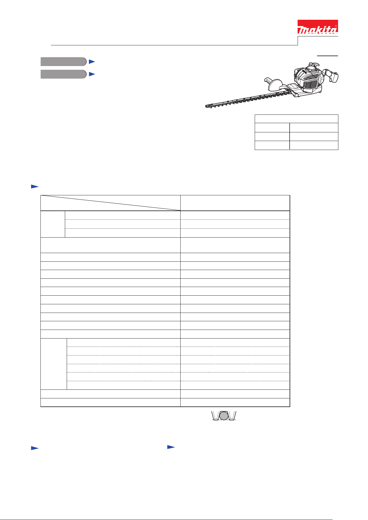
EH7500S
PRODUCT
P 1/ 25
Description
Petrol Hedge Trimmer
CONCEPT AND MAIN APPLICATIONS
Model EH7500S is a 22.2cm³ 2-stroke petrol hedge trimmer
with single-sided blade in compliance with all known exhaust
emission regulations, featuring extra light design with further
improvements in noise, vibration and handling compared with
our current models.
Especially, the lightweight design is outstanding.
4.7kg (10.4lbs) dry weight is the world’s lightest among all petrol
hedge trimmers in compliance with any exhaust emission regulation
as of February, 2010.
Specification
Specifications
Type
Engine Displacement: cm³
Fuel
In compliance with main exhaust emission regulations;
CARB Tier 3, EPA Phase 2, EU Stage 2
Max. output power: kW (PS) 0.68 (1.0) [at 7,500 min.ˉ¹]
Max. torque: N.m
Stroke rate at No load: min.
Max. cutting capacity: mm (") 728 (25-5/8)
Carburetor
Clutch Yes
Rotation limiter Yes
Type
Length: mm (")
Blade
Max. branch diameter
Net weight*2: kg (lbs)
*1: Indicates maximum diameter of the branch that can be received
between adjacent two blade teeth. (See the figure on right.)
*2: Dry weight
Cutting teeth
Thickness: mm (")
Blade drive mechanism
Tooth spacing: mm (")
ˉ¹ = spm (stroke pre minute)
*1: mm (")
Model
EH7500S
2-stroke
22.2
Mixed gasoline
Yes
0.9 [at 6,000 min.ˉ¹]
4,390
0.4 (13.5)Fuel tank capacity: L (US oz)
Diaphragm
Recoil starterStarting system
YesPrimer pump
Single-sided
750 (29-1/2)
with 3 sharpened edges
2.3 (3/32)
Connecting rod drive
35 (1-3/8)
21.5 (7/8)
4.7 (10.4)
Dimensions: mm (")
Length (L) 1,150 (45-1/4)
Width (W)
Height (H)
323 (12-3/4)
212 (8-3/8)
Standard equipment
Blade cover .................... 1
Socket wrench ................ 1
Hex wrench .................... 1
Note: The standard equipment for the tool
shown above may vary by country.
Optional accessories
Chip receiver set
Page 2

P 2/ 25
Repair
CAUTION: Repair the machine in accordance with “Instruction manual” or “Safety instructions”.
< Note in repair>
* Repair the tool always with gloved hand
* Blades must be covered by Blade cover
* Cool down the engin first before repairing to avoid a skin burn.
* Remove all fuels from fuel tank and carburetor. Avoid any fire from the work shop.
* Repair the tool on the stable work table and keep dust out.
* Record where and how the parts were assembled to avoid mis-assembling.
Assort and reserve the dismantled parts in the box by section.
* The dismantled parts must be treated carefully and washed clean before reassembling.
* Use Impact driver in case bolts or screws can not be loosen by hand.
* The bolts or screws must be tightened to the designated fastening torque.
* Check the movement, sound and alignment of the main parts just after assembled.
* Replace the removed gasket with the new one.
[1] NECESSARY REPAIRING TOOLS
Code No. Description Used for
1R024 Press tool removing Spur gear 9
1R127 Air density tester checking air leakage in Carburetor
1R170 T type hex wrench 3-127 removing / tightening M4 Hex socket head bolt
1R171 T type hex wrench 4-130 removing / tightening M5 Hex socket head bolt
1R229 1/4” hex shank bit removing / tightening Engine section
1R364 Fly wheel puller removing Fly wheel
1R366 Feeler gauge set adjusting a proper gap of ignition coil, Spark plug, Shear blade assembly
1R371 Clutch removing tool removing Clutch
1R373
1R374
Clutch drum removing tool
Pinion gear holding Jig
Hex socket bit 10
Wire brush cleaning Spark plug
removing Clutch drum
fixing Spur gear 9
removing Fly wheel
[2] LUBRICATION
Apply Makita Grease N. No.2 to Spiral spring for recoil starter (approx. 2g) and Gear room (approx. 40g).
Page 3
P 3/ 25
Repair
[3] DISASSEMBLY/ASSEMBLY
[3] -1. Engine section
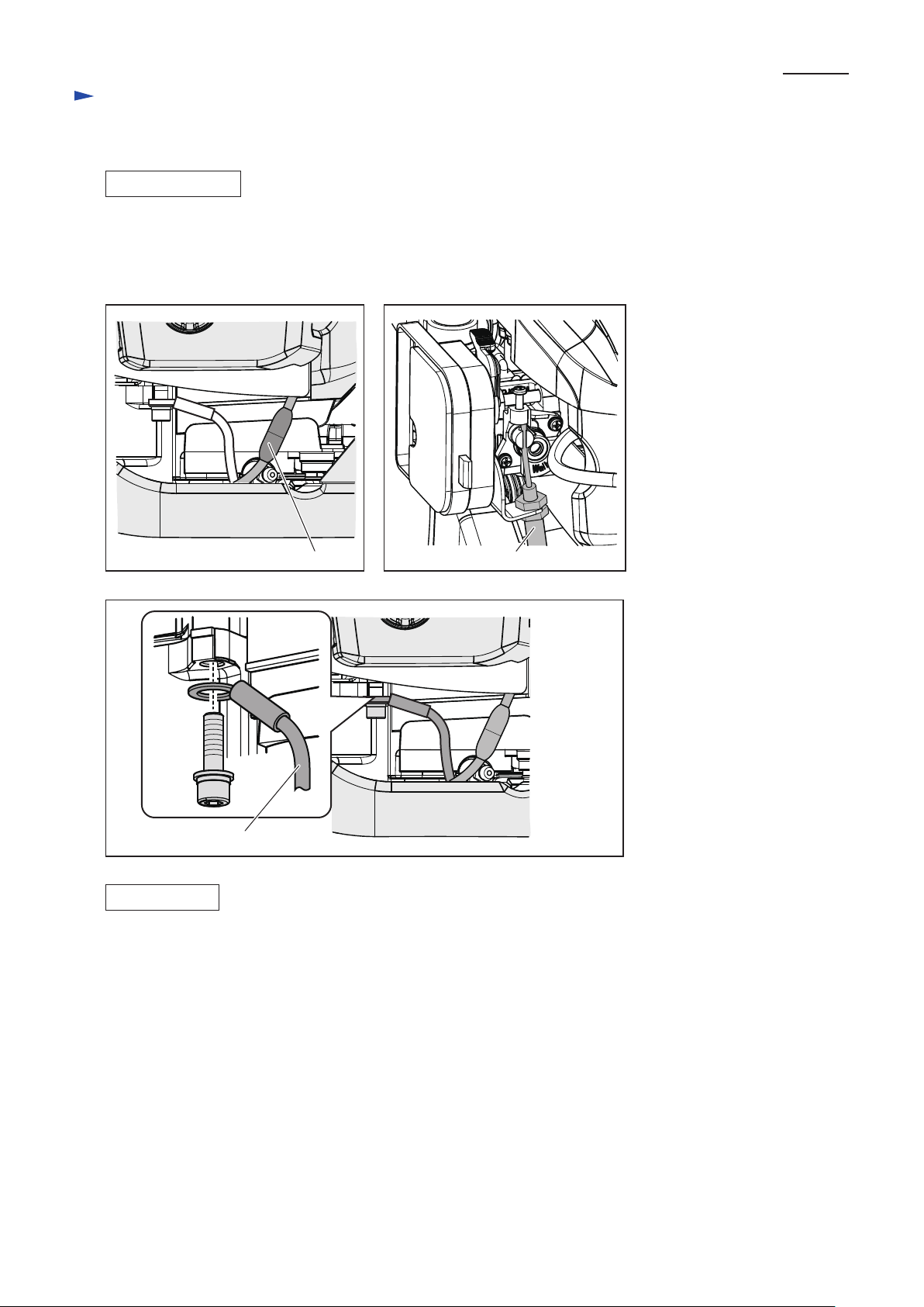
DISASSEMBLING
(1) Disconnect Bullet terminal from the Lead wire of Ignition coil. (Fig. 1)
(2) Remove Air cleaner cover and disconnect control cable from the swivel of carburetor.
Remove Control cable from cable bracket. (Fig. 2)
(3) Remove three bolts to separate engine section. Grounding lead wire is fastened with one of the three bolts. (Fig. 3)
Fig. 1 Fig. 2
Bullet terminal
Fig. 3
Grounding lead wire
ASSEMBLING
(1) Assemble engine section to the Gear housing.
Note: • Do not to pinch the Lead wires between Engine section and Gear housing.
• Make sure to fasten the terminal of Grounding lead wire with one of three Hex socket head bolts.
(2) Fix Control cable along with Adjust screw in the Cable bracket by clamping it with a Nut.
Hook the Control cable end on the Swivel of Carburetor.
Note: Adjust the Cable tension with a 1 - 2 mm play.
(3) Connect Bullet terminals. (Fig. 1)
Control cable
Page 4
Repair
[3] DISASSEMBLY/ASSEMBLY
[3] -2. Clutch Section
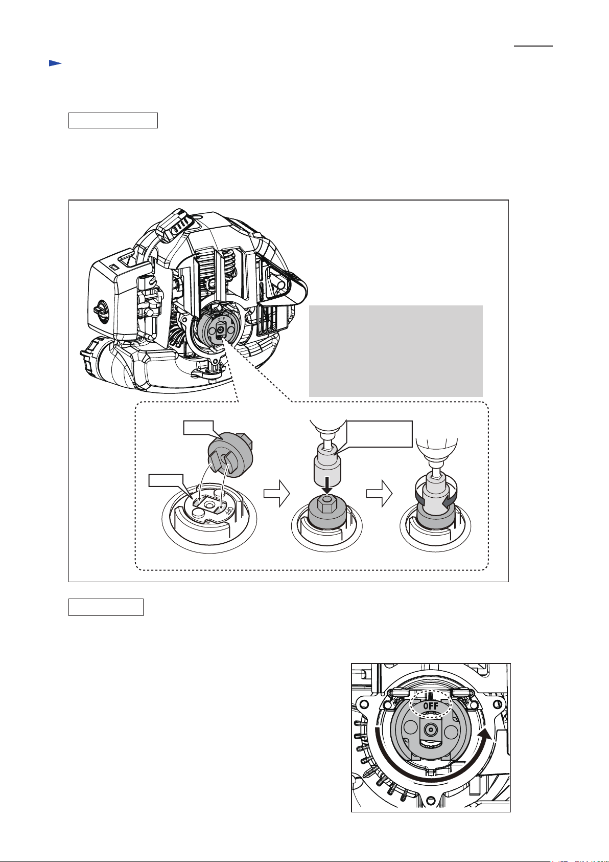
DISASSEMBLING
By using impact driver, Clutch can be loosened without holding Piston by utilizing air pressure in the cylinder.
In order to utilize this air pressure resistant, do not remove Spark plug in this step.
(1) Separate Engine section from Gear housing. (Figs. 1, 2 and 3)
(2) Remove Clutch. (Fig. 4)
Fig. 4
Caution:
Remove Plug cap to avoid
an accidental start of engine.
1. Fit 1R371 to Clutch.
2. Fix 19mm Hex socket bit to
Impact driver.
3. Turn the Clutch clockwise
with Impact driver.
4. Now, the Clutch is removed
from Crankshaft.
P 4/ 25
1R371
Clutch
ASSEMBLING
(1) Drive the Clutch to Crankshaft counterclockwise by hand so that the “ OFF” mark
can face the upper position. (Fig. 5)
(2) Set 1R371 and fasten it counterclockwise by Impact driver
with 19mm Hex socket bit for approx. 2 seconds. (Fig. 4)
19 mm Hex
socket bit
Fig. 5
Page 5
Repair
[3] DISASSEMBLY/ASSEMBLY
[3] -3. Clutch Drum
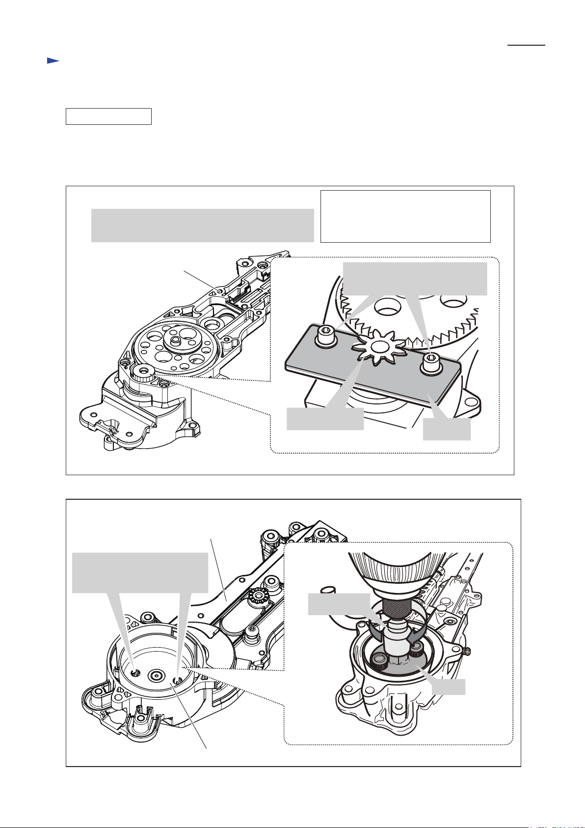
DISASSEMBLING
(1) Separate Gear case from Engine section. (Figs. 1, 2 and 3)
(2) Remove Gear case cover from Gear case.
(3) Disassemble Clutch drum. (Figs. 6 and 7)
Fig. 6
Lock Spur gear 9 with 1R374 for disassembling
Clutch drum located on the reverse side of Spur gear 9.
P 5/ 25
Note:
Hex socket head bolts removed from
Gear case cover can be used for
fixing1R374.
Fig. 7
Gear case
Gear case
(reverse side view)
Hex socket head bolts for fastening
Gear case cover to Gear case
Spur gear 9
1R374
Fix 1R373 to these holes and
remove Clutch drum by turning
1R373 clockwise.
Clutch drum
13 mm Hex
socket bit
1R373
Page 6
P 6/ 25
Repair
[3] DISASSEMBLY/ASSEMBLY
[3] -3. Clutch Drum (cont.)
ASSEMBLING
(1) Lock Spur gear 9 with 1R374. (Fig. 6)
(2) Drive Clutch drum to the shaft of Spur gear 9 counterclockwise by hand.
(3) Mount 1R373 to Clutch drum and fasten it counterclockwise with impact driver and 13 mm Hex socket bit. (Fig. 7)
Note 1: Do not lose Friction plate next to Rod when mounting Clutch drum.
Note 2: Replace Gear case gasket to the new one.
[3] -4. Spur Gear 9
DISASSEMBLING
Remove Spur gear 9. (Fig. 8)
Fig. 8
1. Apply 1R024 to Shaft of
Spur gear 9 and press it
with Arbor press.
1R024
Gear case
ASSEMBLING
Assemble Spur gear 9. (Fig. 9)
Fig. 9
Put Gear housing on the turn base of Arbor press horizontally.
Insert Spur gear 9 into Ball bearing in Gear case and press it with Arbor press.
Shaft of
Spur gear 9
2. Now, Spur gear 9 is disassembled.
Spur gear 9
Gear case complete
Page 7
Repair
[3] DISASSEMBLY/ASSEMBLY
[3] -5. Shear Blade
DISASSEMBLING
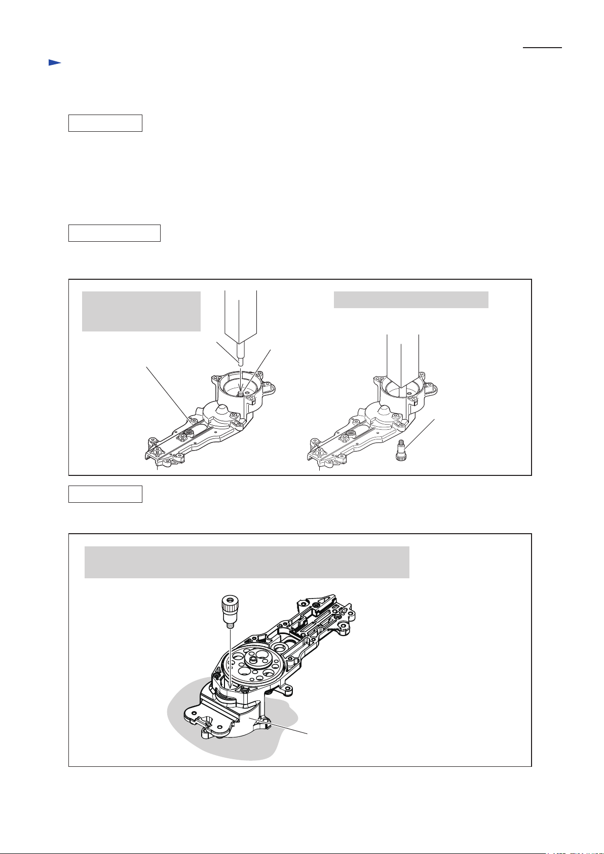
Remove Holder and Shear blade assembly by unscrewing two Hex socket head bolts. (Fig. 10)
Note: 2 pcs. of Sleeve 5 are mounted under Plate. Do not lose them. (Fig. 12)
Fig. 10
Spur gear 43
P 7/ 25
Holder
Gear case
ASSEMBLING
(1) Align the Shear blade (upper) with the lower one. (Fig. 11)
(2) Set 2 pcs. of Sleeve 5 under Plate of Shear blade assembly. (Fig. 12)
(3) Set the position of Spur gear 43 as drawn in Fig. 13.
Fig. 11
Seal
Hex socket head bolt
Note:
Holder and Washer are fastened with Hex socket
Washer
Fig. 12
head bolts. Do not lose them when removing
Shear blade assembly.
Plate
Fig. 13
Shear blades
Sleeve 5
Shear blades
Page 8
P 8/ 25
Repair
[3] DISASSEMBLY/ASSEMBLY
[3] -5. Shear Blade (cont.)
ASSEMBLING
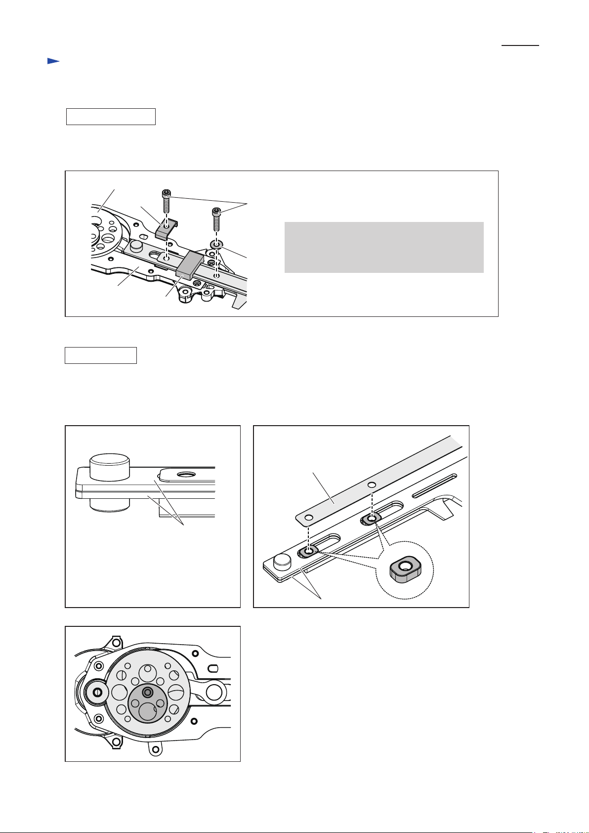
(4) Mount Shear blade assembly in the Gear case while fitting Shear blade’ boss into the hole of Connecting rod.
Fix the Shear blade assembly to Gear case by driving Hex socket head bolt through the Holder and
each Sleeve 5.
Note: • Do not forget to mount Seal. (Fig. 14)
• Apply Makita grease N. No.2 to the portion designated with black triangle. (Fig. 15)
Fig. 14
Spur gear 43
SealHolder
Boss
Gear case
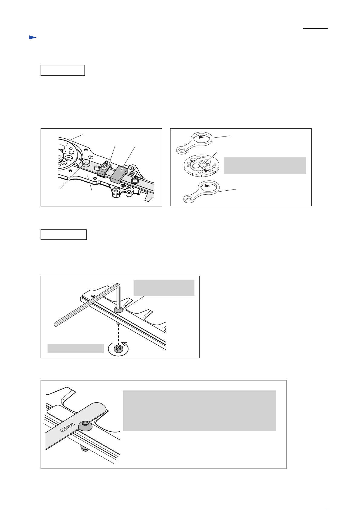
ADJUSTMENT
(1) Loosen Hex lock nut.
(2) After tightening Hex socket button head bolt, turn it back by 1/4 to 3/8 counterclockwise.
(3) Tighten Hex lock nut fully while locking Hex socket button head bolt with Hex wrench. (Fig. 16)
Fig. 16
Lock Hex socket button
head bolt.
Fig. 15
Connecting rod
Cam portion
Apply the both of Cam portions
which accept Connecting rods.
Connecting rod
Tighten Hex lock nut.
(4) Check the clearance by inserting 1R366 into the gaps of all Hex socket button head bolts. (Fig. 17)
Fig. 17
• If 0.4 gauge can be inserted, the clearance is too big.
It causes poor cutting performance.
• If 0.2 gauge can not be inserted, the clearance is too tight.
It causes over consumption of fuel due to high friction load
and heavy load on gears.
Page 9

P 9/ 25
Repair
[3] DISASSEMBLY/ASSEMBLY
[3] -6. Ignition
MAINTENANCE
Plug Cap
(1) Remove Plug cap from Spark plug and check the resistance between Plug cap spring and Ignition coil with circuit
tester. (Fig. 18)
Fig. 18
Spark plug
Grounding terminal
of Ignition coil
If the Circuit tester shows 2.0 ± 0.5 kΩ,
the connection is in order.
(2) Check the connection of Plug cap spring with Ignition cable if Pointer of Circuit tester does not move or
does not steadily indicate 2.0 ± 0.5 caw.
Spray lubricant into the Plug cap and pull out Plug cap spring together with Ignition cable. (Fig. 19)
Fig. 19
Plug cap spring
Ignition cable
Plug cap
Circuit tester
Plug cap
(3) Check Plug cap if there is any crack, damage or disconnection. Re-fix them or replace the damaged one
with the new one if there is any disorder.
(4) Stick a Plug cap spring end into the center of Ignition cable and put them back into Plug cap while holding
Plug cap spring with pliers.
(5) Incomplete connection of Plug cap spring with Ignition cable causes the feeble sparking or no sparking from
Spark plug. Check the connection by taking the same procedure of (1) to (4).
Page 10

Repair
[3] DISASSEMBLY/ASSEMBLY
[3] -6. Ignition (cont.)
MAINTENANCE
Spark Plug
(1) Remove Plug cap with Socket wrench 10-16. Clean the spark terminals of the removed Plug. (Fig. 20)
And adjust the gap of Spark terminals to 0.6 - 0.7 mm.
Fig. 20
P 10/ 25
1. Remove the remaining Fuel and
Carbon deposits stuck in the gap
with wire brush and air duster.
(2) Mount Plug cap on the Plug and contact the Plug’s thread portion to the metal portion of engine, and then,
pull Starter rope gently. The plug is in order if its terminals have sparking constantly.
In case of no sparking at the terminals, return to “MAINTENANCE in [3]-6. Ignition” and replace the Plug with
the new one if the plug is out of order.
DISASSEMBLING
Ignition Coil
(1) Remove Blower housing, Cylinder cover, Muffler cover and Ignition coil.
Note: Do not lose Spacer for insulating Cylinder’s heat when removing Cylinder cover.
(2) Remove Rubber from Insulator. (Fig. 21)
0.6 - 0.7 mm
0.7 mm Feeler
gauge of 1R366
2. Adjust the gap between
Spark terminals to 0.7 mm
by inserting 0.7 mm
Feeler gauge of 1R366.
Fig. 21
Rubber
Page 11

Repair
[3] DISASSEMBLY/ASSEMBLY
[3] -6. Ignition (cont.)
ASSEMBLING
Ignition Coil
(1) Set Spacer on Cylinder and assemble Ignition coil on Spacer while inserting 0.3 mm feeler gauge of
1R366 between Fly wheel’s magnetized portion and Ignition coil. (Fig. 22)
Keep the inserted feeler gauge in this step till the Ignition coil is fully tightened
in order to fix the 0.3 mm gap precisely.
Fig. 22
Ignition coil
0.3 mm
P 11/ 25
Magnetized
portion of
Flywheel
(2) Remove the feeler gauge after Ignition coil is fixed. Make sure that Fly wheel can be turned smoothly by hand
without interference by Ignition coil.
Note: Make sure to fix Ignition coil through the Spacer. High voltage cable and Lead wire must be fixed
into Rubber. Locate high voltage cable to Cylinder side.
(3) Fix Rubber to Insulator.
Note: Make sure that the assembled High voltage cable does not interfere with Throttle in action.
(4) Assemble Cylinder cover.
Note: Tighten Cylinder cover together with Spacer to Cylinder.
Thread locker must be applied to the thread of Hex socket head bolt which tightens that parts.
Apply “ThreeBond 1342” or “Loctite 242” as a thread locker.
(5) Assemble Muffler cover.
Note: Apply “ThreeBond 1342” or “Loctite 242” as a thread locker.
Page 12

P 12/ 25
Repair
[3] DISASSEMBLY/ASSEMBLY
[3] -6. Ignition (cont.)
DISASSEMBLING
Fly Wheel
Note: Plug cap has to be removed in order to avoid accidental start of engine.
Do not remove Plug when the nut for tightening Fly wheel is loosened to utilize air resistant in Cylinder.
(1) Attach 10 mm Hex socket bit to Impact driver. Turn M6 Hex nut counterclockwise with a Impact driver
(Clutch is removed by turning clockwise). (Fig. 23)
Fig. 23
1. Turn Hex nut counterclockwise.
So the Hex nut can be removed.
Piston
Clutch
2. Clutch is removed by
Clutch side
(2) Set 1R364 to Fly wheel with two M6 bolts. Tighten Both of two M6 bolts to the same depth.
Fig. 24
turning clockwise.
1R364
Hex Nut
Fly wheel
M6 Bolt
Page 13

P 13/ 25
Repair
[3] DISASSEMBLY/ASSEMBLY
[3] -6. Ignition (cont.)
ASSEMBLING
Fly Wheel
(1) Remove oil completely from Crankshaft.
(2) Align Woodruff key on Crank shaft to the key groove of Fly wheel and mount Fly wheel to Crankshaft.
(3) Turn M6 Hex nut to Crankshaft clockwise by hand and tighten it with Impact driver with 10 mm Socket bit
clockwise for 2 second.
Fig. 25
1. Remove Oil completely
from Crankshaft.
Woodruff Key
2. Align this Key to the groove
in the Fly wheel.
[3] -7. Recoil Starter
DISASSEMBLING
(1) Remove Recoil starter assembly from Blower housing.
Note: Record the position and the pulling direction of Starter knob before disassembling. (Fig. 26)
Fig. 26
Recoil starter assembly
Blade sideLever case side
Starter knob
Pulling direction
Page 14

Repair
[3] DISASSEMBLY/ASSEMBLY
[3] -7. Recoil Starter (cont.)
DISASSEMBLING
(2) Disassemble Recoil starter. (Fig. 27)
Fig. 27
P 14/ 25
1. Pull out Rope by the length of one or two times
turn of the Reel and hold the Reel.
Reel
Notch
Starter knob
Rope
3. Remove Set screw, Cam and Torsion spring.
2. Release Starter knob while holding the Reel with
your finger and pull the slack Rope inside.
Hook the Rope in the notch and turn the Reel
counterclockwise while braking the Reel and
holding the Rope. Turn Reel until
Spiral spring recoil force is gone.
Reel
Notch
Starter
case
Rope
4. Remove Reel from Starter case.
Note: Do not let Spiral spring leap out
in this step.
Set screw
Cam
Reel Torsion spring
Reel
Spiral spring
Page 15

Repair
[3] DISASSEMBLY/ASSEMBLY
[3] -7. Recoil Starter (cont.)
ASSEMBLING
Assemble the Recoil starter. (Figs. 28 and 29)
Fig. 28
P 15/ 25
Spiral spring
2. Pass the new Starter rope through Starter case and
tie the both Rope ends in Starter knob and Reel.
And wind the Rope around Reel two or three times.
Starter case
Starter knob
Reel
1. Set the outer end of Spiral spring here firstly and wind it
clockwise till it is completely installed in the Starter case.
Note: Apply Makita grease N. No.2 a little on
the Spiral spring (Red grease was applied
to it at ex-factory condition).
3. Fit the projection of Reel to the hook of Spiral spring
while turning Reel clockwise.
Projection of Reel
Hook of Spiral spring
Note: Precisely fit the projection of Reel to the hook of
Spiral spring by repeating the step 3.
Set screw
Cam
Torsion spring
Mounted Reel
Fig. 29
6. Hold the rope near by the notch and turn it
with the Reel clockwise to let Spiral spring
have recoil force for driving Reel.
Reel
4. Fix Torsion spring and Cam
on the Reel with Set screw.
Notch
5. Pull the slack rope in the Starter case
and hook it in the notch of Reel.
Reel
Rope
7. Remove the rope from the notch and release your finger from Reel.
The Reel turns counterclockwise. Repeat the actions of 5, 6, 7,
until the Rope is wound by the Reel completely.
Notch
Starter case
RopeReel
Rope
Page 16

Repair
[3] DISASSEMBLY/ASSEMBLY
[3] -8. Carburetor
DISASSEMBLING, CLEANING
(1) Remove Air cleaner cover. (Fig. 30)
(2) Remove Elements, Sponge and Felt. (Fig. 31)
Fig. 30 Fig. 31
P 16/ 25
Air cleaner
cover
(3) Remove two Hex socket head bolts fixing Air cleaner plate and Carburetor assembly. (Fig. 32)
Note: Take off the Hex socket head bolts completely from the machine,
otherwise, it’s impossible to disassemble Carburetor.
(4) Remove two tubes and disassemble Carburetor assembly. (Fig. 32)
Fig. 32
Element
(Felt made)
Element
(Sponge made)
Clear Tube
Carburetor
assembly
Hex socket
head bolt
Black
Air cleaner plate
Hex socket
head bolt
(5) Remove Diaphragm cover, Metaling diaphragm, Gasket set by unscrewing four Pan head screws. (Fig. 33)
Note: Carefully separate Gasket from Metaling diaphragm in case they stick each other as they are fragile.
(6) Replace Metaling diaphragm to the new one if it has any curing, deformation or breakage.
Fig. 33
Throttle valve
assembly
Pan head screw (small) Pan head screw (4pcs.)
Pump diaphragm
Gasket
Carburetor
body assembly
Tube
Inlet
screen
Pump body assembly
Metaling
diaphragm
Gasket
Diaphragm
cover
Page 17

Repair
[3] DISASSEMBLY/ASSEMBLY
[3] -8. Carburetor (cont.)
DISASSEMBLING, CLEANING
(7) Check Inlet needle in the Pump body assembly if its tip is intact. Replace Controller set including Inlet needle
to the new set if Inlet needle tip is damaged. It can be removed by unscrewing M3x4 Set screw.
Check if there is any foreign material stuck on Fuel inlet before fixing Inlet needle. (Figs. 33, 34 and 35)
(8) Fully loosen idling screw, then, remove Pan head screws (small) for fixing Throttle valve assembly
to Carburetor body.
(9) Spray carburetor cleaner on the Inlet screen, all fuel inlets, outlets and internal routes. And then, wash them
with gasoline. (Fig. 35)
Fig. 34 Fig. 35
P 17/ 25
Component Parts of Controller set
Countersunk
head screw
Compression spring
Note:
The above parts are not supplied individually.
In case of replacement of any of the above parts,
it has to be replaced as a Pump body assembly.
(10) Make sure that Compression spring fits to the protrusion of Control lever when assembled. (Fig. 36R)
Metaling diaphragm
Inlet needle
Pin
Control lever
Inlet needle
in normal condition
Carbureted air leaks out
if foreign material sticks
at inlet hole.
Fig. 36FFig. 36R
Wrong Assembling of Compression spring
Carbureted air leaks out
if Inlet needle is worn out.
worn out
Control lever
Inlet needle
Compression spring
fits to the projection
of Control lever.
Compression spring
Projection of
Control lever
Page 18

Repair
[3] DISASSEMBLY/ASSEMBLY
[3] -8. Carburetor (cont.)
ASSEMBLING
Assemble by reversing the disassembly, cleaning procedure.
AIR-TIGHT TEST
See Fig. 37.
Fig. 37
P 18/ 25
Carburetor
Nipple for
fuel intake
1R127
ASSEMBLING CARBURETOR TO ENGINE
(1) Connect two Tubes to Carburetor. (Fig. 38)
Fig. 38
1. Connect 1R127 to Carburetor.
2. Push up the air pressure until
the pressure gauge indicates
0.05 Mpa.
3. The Carburetor is in order
if the air pressure of 0.05 Mpa
can be kept for 10 seconds.
Push
Nipple for
fuel intake
Clear Tube
Black Tube
Page 19

Repair
[3] DISASSEMBLY/ASSEMBLY
[3] -8. Carburetor (cont.)
ASSEMBLING CARBURETOR TO ENGINE
(2) Fasten the following parts with two Hex socket head bolts. (Fig. 39)
* Plate
* Air cleaner plate
* Gasket
* Cable bracket
* Gasket
* Carburetor assembly
* Carburetor gasket
Fig. 39
P 19/ 25
Starter case
Air cleaner plate
Hex socket
head bolt
(2pcs.)
Plate
Note 1:
Assemble plate to Air cleaner plate
while facing its triangle side to
Starter case side.
Gasket
Cable bracket
Gasket
Carburetor gasket
Carburetor
assembly
Note 3:
Make sure that Gaskets
are mounted to the both
side of Cable bracket.
Note 2:
Assemble Carburetor gasket
while facing its cut portion
to Loop handle side.
(3) Assemble Elements. (Fig. 40)
Fig. 40
1. First, assemble Felt element, and then, Sponge element.
2. Fit the tab of Air cleaner plate with the square hole of
Air cleaner cover and fasten Air cleaner cover
with a screw.
Air cleaner plate
Element (felt)
Element (sponge)
Air cleaner cover
Tab of
Air cleaner plate
Square hole
for tab
Page 20

Repair
[3] DISASSEMBLY/ASSEMBLY
[3] -9. Stop Switch
MAINTENANCE
(1) Connect Circuit tester for checking Stop switch. (Fig. 41)
Fig. 41
Connecting terminal
P 20/ 25
Bullet terminal
Stop switch is in order if it works as followings:
* Circuit tester shows no connectivity
when Engine ON
* Circuit tester shows a connectivity
when Engine OFF
Page 21

Repair
[3] DISASSEMBLY/ASSEMBLY
[3] -10. Fuel Tube
TUBING
Connect Fuel tank, Primer pump, Carburetor with Tubes. (Fig. 42)
Fig. 42
1. Mount Tube complete (equipped with black Tube and clear Tube) to Fuel tank.
The black Tube is for Fuel inlet. Insert Fuel filter to the black one with Hose clamp.
And then, put Fuel filter into the Tank.
Fuel filter
P 21/ 25
Fuel tank
Tube complete
2. Connect the clear tube to the longer nipple of Primer pump.
Fuel tank
3. Connect the black tube to the nipple for fuel inlet of Carburetor.
4. Connect the outlet nipple of Carburetor and shorter nipple of
Primer pump with another clear Tube.
Hose clamp
Fuel tank
Page 22

Repair
[3] DISASSEMBLY/ASSEMBLY
[3] -11. Spark Arrestor
DISASSEMBLING, CLEANING
(1) Separate Engine from the product. (Figs. 1, 2 and 3)
(2) Disassemble Muffler section. (Fig. 43)
Fig. 43
P 22/ 25
1. Remove Muffler cover (outer). And remove two Hex socket
head bolts. So, Muffler and Inner muffler cover (metal made)
are removed.
Inner muffler cover
(metal made)
Hex socket
head bolt
Muffler
3. Unscrew three Pan head screws
and remove Tail pipe, Gasket and
Spark arrestor from Muffler.
Muffler cover (outer)
4. Remove the carbon deposits and dust from Spark arrestor if any.
Replace the Arrestor if it has any deformation or breakage.
Spark arrestor
Muffler
2. Remove Inner muffler cover (metal)
and Muffler gasket from Muffler.
Muffler gasket
Muffler
Tail pipe
Pan head screw (3 pcs.)
Inner muffler cover
(metal made)
Gasket
ASSEMBLING
(1) Set Spark arrestor to Muffler.
(2) Put Gasket on the Spark arrestor while facing its cut corner to the hill formed portion of Muffler. (Fig. 44)
(3) Assemble Tail pipe through Gasket to Muffler with three Pan head screws. (Fig. 44)
Fig. 44
2. The Gasket has convex portion
on the reverse side for pressing
1. The hole comes under
the Hill formed portion of
Muffler when assembled.
Mount Gasket while facing this cut corner to the Hill formed portion of Muffler
so that the convex side of Gasket presses the Spark arrestor.
Muffler gasket
Hill formed portion
Spark arrestor
Spark arrestor to Muffler surface.
Gasket
Tail pipe
(4) Mount Inner muffler cover. (Fig. 43)
(5) Fix the assembled muffler section to Engine with Hex socket head bolts. (Fig. 43)
Note: Apply “Loctite 242” or “ThreeBond 1342” to the thread of Hex socket head bolts.
Page 23

Repair
[3] DISASSEMBLY/ASSEMBLY
[3] -12. Engine Block
DISASSEMBLING
(1) Disassemble the following parts from Engine.
* Blower housing * Muffler cover (out side) * Muffler * Cylinder cover
* Plug cap * Spark plug * Ignition coil * Carburetor
* Clutch * Fly wheel
(2) Remove Fuel tank while paying attention not to lose Spacer which is fixed in between the Tank and Engine.
(3) Remove Insulator with Insulator gasket from Cylinder.
(4) Separate Cylinder from Crankcase assembly and remove Piston. (Fig. 45)
Fig. 45
P 23/ 25
Cylinder
Cylinder gasket
Piston
Crankcase
assembly
1. Remove Piston clips from the both
side of Piston with the awl.
Note: Do not reuse the removed
Piston clip.
2. Remove Piston pin by pushing it
with 1R171.
Now, Piston can be removed
Crankshaft
from Crankshaft.
Fly wheel
side
Piston
Piston pin
Piston clip
Awl
Piston pin
Piston clip
1R171
ASSEMBLING
(1) Before assembling Piston, apply one or two drops 2 stroke engine oil to Needle bearing on Crank shaft.
(2) Assemble Piston to Crank shaft. (Fig. 46)
Fig. 46
Assemble Piston at the direction described below.
Left
Cavity
Right
Fly wheel
side
Page 24

Repair
[3] DISASSEMBLY/ASSEMBLY
[3] -12. Engine Block (cont.)
ASSEMBLING
(3) Assemble the new Piston clip with Awl. (Fig. 47)
Fig. 47
Piston clip opening must face to either the top side or
Skirt side of Piston when assembled.
Groove on Piston Groove on Piston
Top Side
P 24/ 25
Top Side
Skirt Side
(4) Assemble Piston rings (Fig. 48).
Fig. 48
The first nock pin
in the lower groove
1. Mount Piston ring to
the lower groove while
aligning its opening gap
to the first nock pin.
Piston clip
Top view of Piston
The second nock pin
in the upper groove
Skirt Side
Note 1:
Carefully open Piston ring when fixed
so as not to break it.
Note 2:
Face cut surface to the top
when Piston ring is assembled.
2. Mount another Piston ring
to the upper groove while
aligning its opening gap
to the second nock pin.
(5) Assemble Cylinder gasket to Cylinder. (Fig. 49)
Fig. 49
1. Apply 2 stroke engine oil to the internal
surface of Cylinder before assembling it
to Crankcase assembly.
2. Assemble Cylinder gasket
while aligning its square
hole to that of Cylinder.
Cylinder
Cylinder gasket
Page 25

Repair
[3] DISASSEMBLY/ASSEMBLY
[3] -12. Engine Block (cont.)
ASSEMBLIG
(6) Mount Cylinder to Crankcase assembly. (Fig. 50)
Fig. 50
P 25/ 25
Cylinder
1. Insert Cylinder over Piston
while pressing Piston rings
toward the Piston’s center.
Note:
Pay attention not to let Piston
rings to move onto Nock pins
when it’s assembled to Cylinder
(Fig. 48).
Piston rings will break
if Cylinder is mounted by force
over Piston rings that are
moved onto Nock pins.
(7) Assemble Insulator to Cylinder.
Note: Apply “ThreeBond 1342” or “Loctite 242” to the thread of Hex socket head bolt.
(8) Assemble Fuel tank.
Note: • Do not forget to mount Spacer between Fuel tank and Clutch case assembly.
• Apply “ThreeBond 1342” or “Loctite 242” to the thread of Hex socket head bolt.
2. Tighten four Hex socket
head bolts in diagonal
order.
Piston
Crankcase assembly
[3] -13. Fastening Torque
Part description
Crankcase 1 Crankcase 2 M5x18 Hex Socket Head Bolt
Cylinder Crankcase M5x18 Hex Socket Head Bolt 8
Fly wheel Crankshaft 1 M6 Nut 12
Coil Cylinder M4x20 Hex Socket Head Bolt 4
Muffler Cylinder M5x50 Hex Socket Head Bolt 8
Muffler cover Muffler M5x5 Screw 4
Clutch Crankshaft 2 M8 Screw (Left Hand Thread) 12
Recoil starter Blower housing 4.5x14 Tapping Screw 2.5
Plug Cylinder M10 10
Spur gear 9 Clutch drum M8 Screw (Left Hand Thread) 8
Grease nipple Gear case M6 4
Gear case cover Gear case M4x16 Hex Socket Head Bolt 4
Blade guard Guide bar M5x6 Screw 3.5
Plate Guide bar M5x8 Screw 3.5
Bolt and Screw
Fastening
Torque (N. m)
8
 Loading...