


Makita BTD133, BTD145 Manual
|
GB |
Cordless Impact Driver |
Instruction Manual |
|
|
|
|
|
|
Tournevis à Chocs sans Fil |
Manuel d’instructions |
|
F |
||
|
|
|
|
|
|
Akku-Schlagschrauber |
Betriebsanleitung |
|
D |
||
|
|
|
|
|
|
Avvitatore ad impulso a batteria |
Istruzioni per l’uso |
|
I |
||
|
|
|
|
|
|
Accu-slagschroevendraaier |
Gebruiksaanwijzing |
|
NL |
||
|
|
|
|
|
|
Atornillador de Impacto Inalámbrico |
Manual de instrucciones |
|
E |
||
|
|
|
|
|
|
Parafusadeira de Impacto a Bateria |
Manual de instruções |
|
P |
||
|
|
|
|
|
|
Akku slagskruetrækker |
Brugsanvisning |
|
DK |
||
|
|
|
|
|
|
Ασύρματ κρ υστικ ιδ τρύπαν |
δηγίες ρήσεως |
|
GR |
||
|
|
|
|
BTD133
BTD145

|
|
2 |
|
1 |
4 |
|
|
|
|
|
3 |
1 |
|
2 |
S |
H |


 6 5
6 5 


3
A 


 B
B 

 7
7
5
S |
H |
13
4
8
S |
H |
9 |
|
10 |
S |
H |
|
|
S |
H |
11 |
|
S |
H |
12
6
7 |
8 |
2 |
|
14 |
15 |
|
9 |
|
|
|
|
19 |
|
17 |
18 |
|
|
|
11 |
|
|
20 |
|
|
N m (kgf
 cm)
cm)
120 |
|
|
|
|
|
|
|
|
(1224) |
|
|
|
|
|
|
M14 |
|
|
|
|
|
|
|
|
||
100 |
|
|
|
|
|
|
|
|
|
|
|
|
|
|
|
||
(1020) |
|
|
|
|
|
|
|
|
|
|
|
|
|
|
|
||
80 |
|
|
|
|
|
|
|
|
|
|
|
|
|
|
|
||
(816) |
|
|
|
|
|
M12 |
|
(M14) |
|
|
|
|
|
|
|
||
21 |
|
|
|
|
|
|
||
|
|
|
|
|
|
22 |
||
60 |
|
|
|
|
|
|
||
(612) |
|
|
|
M10 |
|
|
||
|
|
|
|
|
|
(M12) |
||
40 |
|
|
|
|
|
|
|
|
|
|
|
|
|
|
|
|
|
(408) |
|
|
|
M8 |
|
|
||
20 |
|
|
|
|
(M10) |
|||
|
|
|
|
|
|
|
||
|
|
|
|
|
|
|
|
|
(204) |
|
|
|
|
|
|
(M8) |
|
|
|
|
|
|
|
|||
|
|
|
|
|
|
|
|
|
|
|
|
|
|
|
|
|
|
0 |
1.0 2.0 3.0 (S) |
|||||||
23
14 |
15 |
16 |
10
12
24
N m
m
(kgf cm) |
|
|
|
120 |
|
M12 |
|
|
|||
(1224) |
|
||
100 |
|
|
(M12) |
|
|
||
(1020) |
|
M10 |
|
80 |
|
||
|
|
|
|
(816) |
|
|
|
21 |
60 |
|
|
|
|
|
|
|
(M10) |
22 |
|
(612) |
|
M8 |
|
||||||
|
|
|
|
|||||||
|
40 |
|
|
|
|
|
|
|
|
|
|
|
|
|
|
|
|
|
|
|
|
|
(408) |
|
|
|
|
|
|
|
(M8) |
|
|
20 |
|
|
|
|
|
|
|
|
|
|
|
|
|
|
|
|
|
|
|
|
|
|
|
|
|
|
|
|
|
|
|
|
(204) |
|
|
|
|
|
|
|
|
|
|
|
|
|
|
|
|
|
|
|
|
|
0 |
1.0 2.0 3.0 (S) |
|
|||||||
|
|
|
23 |
|
|
|
|
|
||
13 |
14 |
3

ENGLISH (Original instructions)
Explanation of general view
1 |
Button |
9 |
Hard |
17 |
Hook |
2 |
Red part |
10 |
Medium |
18 |
Screw |
3 |
Battery cartridge |
11 |
Soft |
19 |
Groove |
4 |
Switch trigger |
12 |
Hammering force button |
20 |
Standard bolt |
5 |
Lamp |
13 |
LED indicator |
21 |
Fastening torque |
6 |
Light button |
14 |
Bit |
22 |
Proper fastening torque |
7 |
Reversing switch lever |
15 |
Bit-piece |
23 |
Fastening time |
8 |
Changed in three steps |
16 |
Sleeve |
24 |
High tensile bolt |
SPECIFICATIONS
|
Model |
BTD133 |
BTD145 |
|
|
|
|
|
|
|
Machine screw |
4 mm – 8 mm |
4 mm – 8 mm |
|
|
|
|
|
|
Capacities |
Standard bolt |
5 mm – 14 mm |
5 mm – 14 mm |
|
|
|
|
|
|
|
High tensile bolt |
5 mm – 12 mm |
5 mm – 12 mm |
|
|
|
|
|
|
|
Hammer mode (Hard) |
0 – 2,400 |
0 – 2,600 |
|
No load speed (min–1) |
|
|
|
|
Hammer mode (Medium) |
0 – 1,800 |
0 – 2,000 |
||
|
Hammer mode (Soft) |
0 – 1,100 |
0 – 1,300 |
|
|
|
|
|
|
|
Hammer mode (Hard) |
0 – 3,200 |
0 – 3,400 |
|
|
|
|
|
|
Impacts per minute |
Hammer mode (Medium) |
0 – 2,600 |
0 – 2,800 |
|
|
|
|
|
|
|
Hammer mode (Soft) |
0 – 1,100 |
0 – 1,300 |
|
|
|
|
|
|
Overall length |
With one-touch bit holder 139 mm |
|||
Without one-touch bit holder 140 mm |
||||
|
|
|||
|
|
|
||
Net weight (with battery cartridge) |
1.4 kg |
1.3 kg |
||
|
|
|
||
Rated voltage |
D.C. 14.4 V |
D.C. 18 V |
||
|
|
|
|
|
•Due to our continuing programme of research and development, the specifications herein are subject to change without notice.
•Specifications and battery cartridge may differ from country to country.
•Weight, with battery cartridge, according to EPTA-Pro- cedure 01/2003
ENE033-1
Intended use
The tool is intended for screw driving in wood, metal and plastic.
GEA010-1
General Power Tool Safety Warnings
 WARNING Read all safety warnings and all instructions. Failure to follow the warnings and instructions may result in electric shock, fire and/or serious injury.
Save all warnings and instructions for future reference.
GEB054-1
CORDLESS IMPACT DRIVER
SAFETY WARNINGS
1.Hold power tool by insulated gripping surfaces, when performing an operation where the fastener may contact hidden wiring. Fasteners contacting a “live” wire may make exposed metal parts of the power tool “live” and could give the operator an electric shock.
2.Always be sure you have a firm footing.
Be sure no one is below when using the tool in high locations.
3.Hold the tool firmly.
4.Wear ear protectors.
SAVE THESE INSTRUCTIONS.
 WARNING:
DO NOT let comfort or familiarity with product (gained from repeated use) replace strict adherence to safety rules for the subject product.
MISUSE or failure to follow the safety rules stated in this instruction manual may cause serious personal injury.
4

ENC007-6
IMPORTANT SAFETY INSTRUCTIONS
FOR BATTERY CARTRIDGE
1.Before using battery cartridge, read all instructions and cautionary markings on (1) battery charger, (2) battery, and (3) product using battery.
2.Do not disassemble battery cartridge.
3.If operating time has become excessively shorter, stop operating immediately. It may result in a risk of overheating, possible burns and even an explosion.
4.If electrolyte gets into your eyes, rinse them out with clear water and seek medical attention right away. It may result in loss of your eyesight.
5.Do not short the battery cartridge:
(1)Do not touch the terminals with any conductive material.
(2)Avoid storing battery cartridge in a container with other metal objects such as nails, coins, etc.
(3)Do not expose battery cartridge to water or
rain.
A battery short can cause a large current flow, overheating, possible burns and even a breakdown.
6.Do not store the tool and battery cartridge in locations where the temperature may reach or exceed 50°C (122°F).
7.Do not incinerate the battery cartridge even if it is severely damaged or is completely worn out. The battery cartridge can explode in a fire.
8.Be careful not to drop or strike battery.
9.Do not use a damaged battery.
SAVE THESE INSTRUCTIONS.
Tips for maintaining maximum battery life
1.Charge the battery cartridge before completely discharged.
Always stop tool operation and charge the battery cartridge when you notice less tool power.
2.Never recharge a fully charged battery cartridge. Overcharging shortens the battery service life.
3.Charge the battery cartridge with room temperature at 10°C – 40°C (50°F – 104°F). Let a hot battery cartridge cool down before charging it.
FUNCTIONAL DESCRIPTION
 CAUTION:
•Always be sure that the tool is switched off and the battery cartridge is removed before adjusting or checking function on the tool.
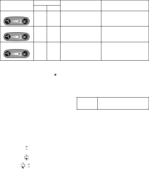
Installing or removing battery cartridge (Fig. 1)
•Always switch off the tool before insertion or removal of the battery cartridge.
•To remove the battery cartridge, withdraw it from the tool while sliding the button on the front of the cartridge.
•To insert the battery cartridge, align the tongue on the battery cartridge with the groove in the housing and slip it into place. Always insert it all the way until it locks in place with a little click. If you can see the red part on the upper side of the button, it is not locked completely. Insert it fully until the red part cannot be seen. If not, it may accidentally fall out of the tool, causing injury to you or someone around you.
•Do not use force when inserting the battery cartridge. If the cartridge does not slide in easily, it is not being inserted correctly.
Switch action (Fig. 2)
 CAUTION:
•Before inserting the battery cartridge into the tool, always check to see that the switch trigger actuates properly and returns to the “OFF” position when released.
To start the tool, simply pull the switch trigger. Tool speed is increased by increasing pressure on the switch trigger. Release the switch trigger to stop.
NOTE:
•Continuing to pull the trigger switch for more than 130 seconds will stop the tool.
Lighting up the front lamp (Fig. 3 & 4)
 CAUTION:
•Do not look in the light or see the source of light directly.
Every time the light button  on the switch panel is pressed, the light status is alternatively changed from the ON to the OFF and from the OFF to the ON.
With the light button in the ON status, pull the switch trigger to turn on the light. To turn off, release it and the light goes out approximately 10 seconds after releasing.
With the light button in the OFF status, even if the trigger is pulled, the lamp will not light on.
NOTE:
•To make sure the status of light, pull the trigger. When the lamp lights up by pulling the switch trigger, the light switch is in the ON status. When the lamp does not come on, the light switch is in the OFF status.
•During the operation of switch trigger, the light status cannot be changed.
•For approximately 10 seconds after releasing the switch trigger, the light status can be switched.
Reversing switch action (Fig. 5)
This tool has a reversing switch to change the direction of rotation. Depress the reversing switch lever from the A side for clockwise rotation or from the B side for counterclockwise rotation.
When the reversing switch lever is in the neutral position, the switch trigger cannot be pulled.
 CAUTION:
•Always check the direction of rotation before operation.
•Use the reversing switch only after the tool comes to a complete stop. Changing the direction of rotation before the tool stops may damage the tool.
•When not operating the tool, always set the reversing switch lever to the neutral position.
5
Changing the hammering force (Fig. 6)
Hammering force grade |
Maximum blows |
Application |
Work |
|||
|
|
|||||
displayed on panel |
BTD133 |
BTD145 |
||||
|
|
|||||
|
|
|
|
|||
Hard |
|
|
|
|
Tightening in underwork material / |
|
|
|
3,200 |
3,400 |
Tightening when force and |
||
S |
H |
Tightening long screws / Tightening |
||||
(min–1) |
(min–1) |
speed are desired. |
||||
bolts. |
||||||
|
|
|
|
|
||
Medium |
|
|
|
|
|
|
S |
H |
2,600 |
2,800 |
Tightening when a good |
Tightening in the finishing board, |
|
(min–1) |
(min–1) |
finishing is needed. |
plaster board. |
|||
Soft |
|
|
|
Tightening when excessive |
|
|
|
|
|
tightening need to be avoided |
|
||
|
|
1,100 |
1,300 |
Tightening sash screw / Tightening |
||
S |
H |
because of potentially clogged |
||||
(min–1) |
(min–1) |
small screws such as M6. |
||||
female screw and broken or |
||||||
|
|
|
|
|
||
|
|
|
|
damaged screw head. |
|
|
The hammering force can be changed in three steps: hard, medium and soft.
This allows a tightening suitable to the work.
Every time the hammering force button  is pressed, the number of blows changes in three steps.
For approximately one minute after releasing the switch trigger, the hammering force can be changed.
NOTE:
•When all lamps on the switch panel go out, the tool is turned off to save the battery power. The hammer force grade can be checked by pulling the switch trigger to the extent that the tool does not operate.
•During the operation of switch trigger, the hammer force grade cannot be changed.
Empty signal for remaining battery capacity (Fig. 7)
Pulling the trigger switch when the remaining battery capacity becomes very low makes LED indicator flicker. If the tool is used continuously with the LED indicator flickering up and the battery power is almost used up, the LED indicator will light up and the tool itself will stop. Please refer to the following table for the LED indicator status and the remaining battery capacity.
LED indicator status |
Remaining battery capacity |
||||||||
|
|
|
|
|
|
|
|
|
|
OFF |
|
|
|
|
|
Enough |
|||
|
|
|
|
|
|||||
|
|
|
|
|
|
|
|
|
|
|
|
|
|
|
|
|
|
|
|
Flickering |
|
|
|
|
20% |
||||
|
|
|
|
|
|
|
|
|
|
|
|
|
|
|
|
|
|
|
|
|
|
|
|
|
|
|
|
|
|
Lighting on |
|
|
|
|
|
|
Very low and the tool will |
||
|
|
|
|
|
|
||||
|
|
|
|
|
|
|
|
|
stop. |
|
|
|
|
|
|
|
|
|
|
|
|
|
|
|
|
|
|
|
|
NOTE:
•When all lamps on the switch panel go out, the tool is turned off to save the battery power. The remaining battery capacity can be checked by pulling the switch trigger to the extent that the tool does not operate.
•All of the lamps on the switch panel go out approximately one minute after releasing the switch trigger.
•When the tool temperature is high, the LED indicator may flicker or light up.
•If the LED indicator lights up and the tool stops even with a recharged battery cartridge, cool down the tool temperature fully. When the status is still unchanged, stop using and have the tool repaired by a Makita local service center.
ASSEMBLY
 CAUTION:
•Always be sure that the tool is switched off and the battery cartridge is removed before carrying out any work on the tool.
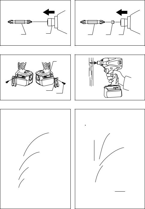
Installing or removing driver bit or socket bit
Use only bits that has inserting portion shown in the figure. (Fig. 8)
For tool with shallow bit hole (Fig. 9)
A = 12 mm
Use only these type of bit. Follow the
B = 9 mm
procedure (1).
(Note) Bit-piece is not necessary.
For tool with deep bit hole (Fig. 10)
A = 17 mm |
To install these types of bits, follow the |
B = 14 mm |
procedure (1). |
|
|
|
To install these types of bits, follow the |
A = 12 mm |
procedure (2). |
B = 9 mm |
(Note) Bit-piece is necessary for |
|
installing the bit. |
|
|
Procedure 1
For tool without one-touch type
To install the bit, pull the sleeve in the direction of the arrow and insert the bit into the sleeve as far as it will go. Then release the sleeve to secure the bit.
For tool one-touch type
To install the bit, insert the bit into the sleeve as far as it will go.
Procedure 2
In addition to the procedure (1) above, insert the bit-piece into the sleeve with its pointed end facing in.
To remove the bit, pull the sleeve in the direction of the arrow and pull the bit out.
NOTE:
•If the bit is not inserted deep enough into the sleeve, the sleeve will not return to its original position and the bit will not be secured. In this case, try re-inserting the bit according to the instructions above.
•When it is difficult to insert the bit, pull the sleeve and insert it into the sleeve as far as it will go.
6
•After inserting the bit, make sure that it is firmly secured. If it comes out, do not use it.
Hook (Fig. 11)
The hook is convenient for temporarily hanging the tool. This can be installed on either side of the tool.
To install the hook, insert it into a groove in the tool housing on either side and then secure it with a screw. To remove, loosen the screw and then take it out.
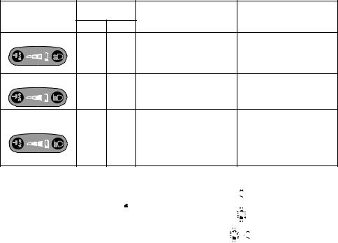
OPERATION
The proper fastening torque may differ depending upon the kind or size of the screw/bolt, the material of the workpiece to be fastened, etc. The relation between fastening torque and fastening time is shown in the figures.
(Fig. 12, 13 & 14)
Hold the tool firmly and place the point of the driver bit in the screw head. Apply forward pressure to the tool to the extent that the bit will not slip off the screw and turn the tool on to start operation.
NOTE:
•Use the proper bit for the head of the screw/bolt that you wish to use.
•When fastening screw M8 or smaller, choose a proper hammer force, and carefully adjust pressure on the switch trigger so that the screw is not damaged.
•Hold the tool pointed straight at the screw.
•If the hammering force is too strong you tighten the screw for a time longer than shown in the figures, the screw or the point of the driver bit may be overstressed, stripped, damaged, etc. Before starting your job, always perform a test operation to determine the proper fastening time for your screw.
The fastening torque is affected by a wide variety of factors including the following. After fastening, always check the torque with a torque wrench.
1.When the battery cartridge is discharged almost completely, voltage will drop and the fastening torque will be reduced.
2.Driver bit or socket bit
Failure to use the correct size driver bit or socket bit will cause a reduction in the fastening torque.
3.Bolt
•Even though the torque coefficient and the class of bolt are the same, the proper fastening torque will differ according to the diameter of bolt.
•Even though the diameters of bolts are the same, the proper fastening torque will differ according to the torque coefficient, the class of bolt and the bolt length.
4.The manner of holding the tool or the material of driving position to be fastened will affect the torque.
5.Operating the tool at low speed will cause a reduction in the fastening torque.
MAINTENANCE
 CAUTION:
•Always be sure that the tool is switched off and the battery cartridge is removed before attempting to perform inspection or maintenance except for the following troubleshooting related to the light.
Cleaning
From time to time wipe off the outside (tool body) of the tool using a cloth dampened in soapy water.
 CAUTION:
• Never use gasoline, benzine, thinner, alcohol or the like. Discoloration, deformation or cracks may result.
Troubleshooting
Trouble |
Light status/LED indicator status/tool status |
|
|
Steps to be taken |
|
|
|
|
|
||||
|
|
Remaining battery capacity level is low. Charge the |
||||
|
|
battery cartridge. |
|
|
||
|
|
When the LED indicator still lights up even after |
||||
|
LED indicator for empty signal for remaining |
charging the battery cartridge, the tool temperature is |
||||
|
battery capacity lights up. |
high. Cool |
down |
it fully. The tool |
restarts after its |
|
|
temperature becomes low. |
|
||||
|
|
|
||||
|
|
When the status is still unchanged, stop using and |
||||
|
|
have the tool repaired by a Makita local service |
||||
|
|
center. |
|
|
|
|
|
|
|
||||
|
Light flickers once per second. |
The tool temperature is high. Cool down it fully. The |
||||
The tool |
tool restarts after its temperature becomes low. |
|||||
|
||||||
stops during |
|
|
|
|
|
|
|
Use the tool with the motor not locked. (When the |
|||||
operation. |
|
|||||
|
tool has stopped due to the motor locking, withdraw |
|||||
|
|
|||||
|
|
the battery cartridge one time and then insert it again |
||||
|
Light flickers five times per second. |
or release |
the |
switch trigger |
for more than |
|
|
|
60 seconds to restart the tool.) |
|
|||
|
|
If the motor still remains locked, stop using and have |
||||
|
|
the tool repaired by a Makita local service center. |
||||
|
|
|
|
|||
|
Switch trigger has been pulled continuously |
Release the switch trigger. |
|
|||
|
for more than 130 seconds. |
|
|
|
|
|
|
Other Symptoms |
Stop using and have the tool repaired by a Makita |
||||
|
local service center. |
|
||||
|
|
|
||||
|
|
|
|
|
|
|
To maintain product SAFETY and RELIABILITY, repairs, any other maintenance or adjustment should be performed by Makita Authorized Service Centers, always using Makita replacement parts.
7

ACCESSORIES
 CAUTION:
•These accessories or attachments are recommended for use with your Makita tool specified in this manual. The use of any other accessories or attachments might present a risk of injury to persons. Only use accessory or attachment for its stated purpose.
If you need any assistance for more details regarding these accessories, ask your local Makita Service Center.
•Screw bits
•Hook
•Plastic carrying case
•Various type of Makita genuine batteries and chargers
•Bit-piece
ENG905-1
Noise
The typical A-weighted noise level determined according to EN60745:
Model BTD133
Sound pressure level (LpA): 92 dB (A) Sound power level (LWA): 103 dB (A) Uncertainty (K): 3 dB (A)
Model BTD145
Sound pressure level (LpA): 93 dB (A) Sound power level (LWA): 104 dB (A) Uncertainty (K): 3 dB (A)
Wear ear protection
ENG900-1
Vibration
The vibration total value (tri-axial vector sum) determined according to EN60745:
Model BTD133
Work mode: impact tightening of fasteners of the maximum capacity of the tool
Vibration emission (ah): 11.0 m/s2 Uncertainty (K): 1.5 m/s2
Model BTD145
Work mode: impact tightening of fasteners of the maximum capacity of the tool
Vibration emission (ah): 12.0 m/s2 Uncertainty (K): 2.0 m/s2
ENG901-1
•The declared vibration emission value has been measured in accordance with the standard test method and may be used for comparing one tool with another.
•The declared vibration emission value may also be used in a preliminary assessment of exposure.
 WARNING:
•The vibration emission during actual use of the power tool can differ from the declared emission value depending on the ways in which the tool is used.
•Be sure to identify safety measures to protect the operator that are based on an estimation of exposure in the actual conditions of use (taking account of all parts of the operating cycle such as the times when the tool is switched off and when it is running idle in addition to the trigger time).
ENH101-15
For European countries only
EC Declaration of Conformity
We Makita Corporation as the responsible manufacturer declare that the following Makita machine(s):
Designation of Machine: Cordless Impact Driver Model No./ Type: BTD133, BTD145
are of series production and
Conforms to the following European Directives:
2006/42/EC
And are manufactured in accordance with the following standards or standardised documents:
EN60745
The technical documentation is kept by our authorized representative in Europe who is:
Makita International Europe Ltd. Michigan Drive, Tongwell,
Milton Keynes, Bucks MK15 8JD, England
6. 11. 2009
Tomoyasu Kato
Director
Makita Corporation
3-11-8, Sumiyoshi-cho,
Anjo, Aichi, 446-8502, JAPAN
8

FRANÇAIS (Instructions originales)
Descriptif
1 |
Bouton |
10 |
Moyen |
18 |
Vis |
2 |
Partie rouge |
11 |
Doux |
19 |
Rainure |
3 |
Batterie |
12 |
Touche de puissance de per- |
20 |
Boulon standard |
4 |
Gâchette |
|
cussion |
21 |
Couple de serrage |
5 |
Lampe |
13 |
Témoin DEL |
22 |
Couple de serrage correct |
6 |
Touche de lumière |
14 |
Embout |
23 |
Temps de serrage |
7 |
Levier inverseur |
15 |
Porte-embout |
24 |
Boulon à haute résistance |
8 |
Trois paliers sont disponibles |
16 |
Manchon |
|
|
9 |
Fort |
17 |
Crochet |
|
|
|
|
|
|
|
|
SPÉCIFICATIONS
|
Modèle |
BTD133 |
BTD145 |
|
|
|
|
|
|
|
Vis à machine |
4 mm – 8 mm |
4 mm – 8 mm |
|
|
|
|
|
|
Capacités |
Boulon standard |
5 mm – 14 mm |
5 mm – 14 mm |
|
|
|
|
|
|
|
Boulon à haute résistance |
5 mm – 12 mm |
5 mm – 12 mm |
|
|
|
|
|
|
|
Mode de percussion (Fort) |
0 – 2 400 |
0 – 2 600 |
|
Vitesse à vide (min–1) |
|
|
|
|
Mode de percussion (Moyen) |
0 – 1 800 |
0 – 2 000 |
||
|
Mode de percussion (Doux) |
0 – 1 100 |
0 – 1 300 |
|
|
|
|
|
|
|
Mode de percussion (Fort) |
0 – 3 200 |
0 – 3 400 |
|
|
|
|
|
|
Coups par minute |
Mode de percussion (Moyen) |
0 – 2 600 |
0 – 2 800 |
|
|
|
|
|
|
|
Mode de percussion (Doux) |
0 – 1 100 |
0 – 1 300 |
|
|
|
|
|
|
Longueur totale |
Avec porte-embout à pose instantanée, 139 mm |
|||
Sans porte-embout à pose instantanée, 140 mm |
||||
|
|
|||
|
|
|
||
Poids net (avec batterie) |
1,4 kg |
1,3 kg |
||
|
|
|
||
Tension nominale |
14,4 V CC |
18 V CC |
||
|
|
|
|
|
•Étant donné l’évolution constante de notre programme de recherche et de développement, les spécifications contenues dans ce manuel sont sujettes à modification sans préavis.
•Les spécifications et la batterie peuvent être différentes suivant les pays.
•Poids, avec la batterie, conformément à la procédure EPTA-01/2003
ENE033-1
Utilisations
L’outil est conçu pour le vissage dans le bois, le métal et le plastique.
GEA010-1
Consignes de sécurité générales pour outils électriques
 MISE EN GARDE Veuillez lire toutes les mises en garde et toutes les instructions. Il y a risque de choc électrique, d’incendie et/ou de blessure grave si les mises en garde et les instructions ne sont pas respectées.
Conservez toutes les mises en garde et instructions pour référence ultérieure.
GEB054-1
CONSIGNES DE SÉCURITÉ POUR
TOURNEVIS À CHOCS SANS FIL
1.Saisissez l’outil électrique par ses surfaces de poigne isolées lorsque vous effectuez une opération au cours de laquelle la visseuse peut entrer en contact avec des fils cachés. Le contact avec un fil sous tension mettra les parties métalliques exposées de la visseuse sous tension, causant ainsi un choc électrique chez l’utilisateur.
2.Ayez toujours une assise ferme sous vos pieds. Veillez à ce que personne ne se trouve en-dessous de vous quand vous utilisez l’outil en hauteur.
3.Tenez votre outil fermement.
4.Portez un casque anti-bruit.
CONSERVEZ CES INSTRUCTIONS.
 AVERTISSEMENT :
NE vous laissez PAS tromper (au fil d’une utilisation répétée) par un sentiment d’aisance et de familiarité avec le produit, en négligeant le respect rigoureux des consignes de sécurité qui accompagnent le produit en question.
La MAUVAISE UTILISATION de l’outil ou l’ignorance des consignes de sécurité indiquées dans ce manuel d’instructions peut entraîner une blessure grave.
9

ENC007-6
PRÉCAUTIONS IMPORTANTES
POUR LA BATTERIE
1.Avant d’utiliser la batterie, lisez toutes les instructions et précautions relatives (1) au chargeur de batterie, (2) à la batterie, et (3) à l’outil utilisant la batterie.
2.Ne démontez pas la batterie.
3.Cessez immédiatement l’utilisation si le temps de fonctionnement devient excessivement court. Il y a risque de surchauffe, de brûlures, voire d’explosion.
4.Si l’électrolyte pénètre dans vos yeux, rincez-les à l’eau claire et consultez immédiatement un médecin. Il y a risque de perte de la vue.
5.Ne court-circuitez pas la batterie :
(1) Ne touchez les bornes avec aucun matériau conducteur.
(2) Évitez de ranger la batterie dans un conteneur avec d’autres objets métalliques, par exemple des clous, des pièces de monnaie, etc.
(3) N’exposez pas la batterie à l’eau ou à la pluie. Un court-circuit de la batterie pourrait provoquer un fort courant, une surchauffe, parfois des brûlures et même une panne.
6.Ne rangez pas l’outil ou la batterie dans des endroits où la température risque d’atteindre ou de dépasser 50°C.
7.Ne jetez pas la batterie au feu même si elle est sérieusement endommagée ou complètement épuisée. La batterie peut exploser au contact du feu.
8.Prenez garde d’échapper ou de heurter la batterie.
9.N’utilisez pas la batterie si elle est abîmée.
CONSERVEZ CES INSTRUCTIONS.
Conseils pour assurer la durée de vie optimale de la batterie
1.Rechargez la batterie avant qu’elle ne soit complètement déchargée.
Arrêtez toujours l’outil et rechargez la batterie quand vous remarquez que la puissance de l’outil diminue.
2.Ne rechargez jamais une batterie complètement chargée. La surcharge réduit la durée de service de la batterie.
3.Chargez la batterie alors que la température de la pièce se trouve entre 10°C et 40°C. Avant de charger une batterie chaude, laissez-la refroidir.
DESCRIPTION DU FONCTIONNEMENT
 ATTENTION :
•Assurez-vous toujours que l’outil est hors tension et que sa batterie est retirée avant de l’ajuster ou de vérifier son fonctionnement.
Installation ou retrait de la batterie (Fig. 1)
•Mettez toujours l’outil hors tension avant d’insérer ou de retirer la batterie.
•Pour retirer la batterie, sortez-la de l’outil tout en faisant glisser le bouton à l’avant de la batterie.
•Pour insérer la batterie, alignez la languette de la batterie avec la rainure située dans le carter, puis faites-la glisser en place. Insérez-la toujours à fond, jusqu’à ce qu’un léger déclic se fasse entendre. Si vous pouvez voir la partie rouge du côté supérieur du bouton, la batterie n’est pas complètement verrouillée. Insérez-la entièrement, jusqu’à ce que la partie rouge ne soit plus visible. Sinon, elle pourrait tomber accidentellement de l’outil, au risque de vous blesser ou de blesser quelqu’un se trouvant près de vous.
•N’appliquez pas une force excessive lors de l’insertion de la batterie. Si la batterie ne glisse pas aisément, c’est qu’elle n’est pas insérée correctement.
Interrupteur (Fig. 2)
 ATTENTION :
•Avant d’insérer la batterie dans l’outil, vérifiez toujours que la gâchette fonctionne bien et revient en position d’arrêt lorsque relâchée.
Pour mettre l’outil en marche, appuyez simplement sur la gâchette. La vitesse de l’outil augmente à mesure que l’on accroît la pression exercée sur la gâchette. Pour l’arrêter, relâchez la gâchette.
NOTE :
•L’outil s’arrêtera si vous maintenez la gâchette enfoncée pendant plus de 130 secondes.
Allumage de la lampe avant (Fig. 3 et 4)
 ATTENTION :
•Evitez de regarder directement le faisceau lumineux ou sa source.
Chaque pression sur la touche de lumière  du tableau de commutateurs fait permuter l’état de la lumière entre ON (activée) et OFF (désactivée).
Avec la touche de lumière activée, appuyez sur la gâchette pour allumer la lumière. Pour désactiver, libérez la gâchette ; la lumière s’éteint environ 10 secondes plus tard. Lorsque la touche de lumière est désactivée, la lampe ne s’allume pas même si vous appuyez sur la gâchette.
NOTE :
•Pour vérifier l’état de la lumière, appuyez sur la gâchette. Si la lampe s’allume lorsque vous appuyez sur la gâchette, le commutateur de lumière est activé. Si la lampe ne s’allume pas, le commutateur de lumière est désactivé.
•Il n’est pas possible de changer l’état de la lumière pendant l’activation de la gâchette.
•Vous pouvez changer l’état de la lumière pendant les quelque 10 secondes qui suivent la libération de la gâchette.
Inverseur (Fig. 5)
L’outil possède un inverseur qui permet de changer le sens de rotation. Enfoncez le levier inverseur du côté A pour une rotation dans le sens des aiguilles d’une montre, ou du côté B pour une rotation dans le sens inverse des aiguilles d’une montre.
La pression sur la gâchette n’est pas possible lorsque le levier inverseur se trouve en position neutre.
 ATTENTION :
•Vérifiez toujours le sens de rotation avant de mettre l’outil en marche.
•N’actionnez l’inverseur qu’une fois que l’outil est complètement arrêté. Si vous changez le sens de rotation avant l’arrêt de l’outil, vous risquez de l’endommager.
•Lorsque vous n’utilisez pas l’outil, placez toujours le levier inverseur en position neutre.
10
Modifier la puissance de percussion (Fig. 6)
Niveau de puissance de |
Nombre max. |
|
|
|
de frappes |
Application |
Travail |
||
percussion affiché sur le tableau |
|
|
||
BTD133 |
BTD145 |
|
|
|
|
|
|
||
Fort |
|
|
|
|
Pour le serrage dans un |
|
|
|
|
|
|
||
S |
H |
3 200 |
3 400 |
Lorsque le serrage exige de la |
matériau de soutien, le |
|
|
|
(min–1) |
(min–1) |
force et de la vitesse. |
serrage de vis longues et le |
|
|
|
|
|
|
serrage de boulons. |
|
Moyen |
|
|
|
|
Pour le serrage dans un |
|
|
|
2 600 |
2 800 Lorsque le serrage exige une |
|||
S |
H |
panneau de finition ou un |
||||
(min–1) |
(min–1) |
belle finition. |
||||
panneau de plâtre. |
||||||
|
|
|
|
|
||
Doux |
|
|
|
Évitez de serrer avec une |
|
|
|
|
|
force excessive car vous |
Pour le serrage des vis pour |
||
|
|
1 100 |
1 300 risqueriez d’abîmer ou de |
|||
S |
H |
châssis / Pour le serrage des |
||||
(min–1) |
(min–1) |
casser la tête de vis, ou de |
||||
petites vis telles que M6. |
||||||
|
|
|
|
boucher le filetage intérieur |
||
|
|
|
|
|
||
|
|
|
|
d’une vis femelle. |
|
|
Trois paliers de puissance de percussion sont disponibles :
fort, moyen et doux.
Cela permet d’effectuer un serrage adapté au type de travail.
Le nombre de frappes change à chaque pression sur la touche de puissance de percussion  , en trois paliers. Vous pouvez modifier la puissance de percussion pendant environ une minute après la libération de la gâchette.
NOTE :
•Lorsque toutes les lampes du tableau de commutateurs sont éteintes, l’outil s’éteint pour économiser la batterie. Vous pouvez vérifier le niveau de puissance de percussion en n’appuyant que partiellement sur la gâchette, pour ne pas activer l’outil.
•Il n’est pas possible de changer le niveau de puissance de percussion pendant l’activation de la gâchette.
Signal de charge faible de la batterie (Fig. 7)
Le témoin DEL clignote si vous appuyez sur la gâchette alors que la charge restante de la batterie est très basse. Le témoin DEL s’allumera et l’outil s’arrêtera si vous l’utilisez de manière continue alors que le témoin DEL est clignotant et que la batterie est presque épuisée.
Reportez-vous au tableau suivant concernant l’état du témoin DEL et la charge restante de la batterie.
État du témoin DEL
Charge restante de la batterie
Éteint |
|
|
|
|
|
Suffisante |
||
|
|
|
|
|
||||
|
|
|
|
|
|
|
|
|
|
|
|
|
|
|
|
|
|
Clignotant |
|
|
20% |
|||||
|
|
|
|
|
||||
|
|
|
|
|
|
|
|
|
|
|
|
|
|
|
|
|
|
Allumé |
|
|
|
|
|
|
|
Très basse et l’outil |
|
|
|
|
|
|
|
|
s’arrêtera. |
|
|
|
|
|
|
|
|
|
NOTE :
•Lorsque tous les voyants du tableau de commutateurs sont éteintes, l’outil s’éteint pour économiser la batterie. Vous pouvez vérifier la charge restante de la batterie en n’appuyant que partiellement sur la gâchette, pour ne pas activer l’outil.
•Toutes les lampes du tableau de commutateurs s’éteignent environ une minute après la libération de la gâchette.
•Lorsque la température de l’outil est élevée, il se peut que le témoin DEL clignote ou s’allume.
•Si le témoin DEL s’allume et que l’outil s’arrête même si la batterie est rechargée, laissez le refroidir complètement. Si cela ne règle pas le problème, cessez l’utilisation et faites réparer l’outil dans le centre de service après-vente Makita le plus près.
ASSEMBLAGE
 ATTENTION :
•Assurez-vous toujours que l’outil est hors tension et que sa batterie est retirée avant d’effectuer tout travail dessus.
Installation ou retrait de l’embout ou l’embout à douille
Utilisez exclusivement les embouts dotés de la partie à insérer indiquée sur la figure. (Fig. 8)
Pour outil à orifice d’embout peu profond (Fig. 9)
A = 12 mm
Utilisez exclusivement ce type
B = 9 mm
d’embout. Suivez la procédure (1). (Note) Porte-embout non requis.
Pour outil à orifice d’embout profond (Fig. 10)
A = 17 mm Pour installer ces types d’embout, B = 14 mm suivez la procédure (1).
Pour installer ces types d’embout, A = 12 mm suivez la procédure (2).
B = 9 mm (Note) Un porte-embout est requis pour installer l’embout.
Procédure 1
Pour outil sans fonction « d’une seule touche »
Pour installer l’embout, tirez le manchon dans le sens de la flèche et insérez l’embout à fond dans le manchon. Libérez ensuite le manchon pour fixer l’embout.
11
Pour outil avec fonction « d’une seule touche »
Pour installer l’embout, insérez-le à fond dans le manchon.
Procédure 2
En plus de la procédure (1) ci-dessus, insérez le porteembout dans le manchon, avec l’extrémité pointue du porte-embout orientée vers l’intérieur du manchon.
Pour retirer l’embout, tirez le manchon dans le sens de la flèche et tirez sur l’embout.
NOTE :
•Si l’embout n’est pas inséré assez profondément dans le manchon, celui-ci ne revient pas à sa position d’origine et l’embout ne se trouve pas bien assuré. En ce cas, insérez à nouveau l’embout comme il est dit ci-dessus.
•S’il est difficile d’insérer l’embout, tirez le manchon et insérez-y l’embout à fond.
•Après avoir inséré l’embout, assurez-vous qu’il est fermement fixé. Ne l’utilisez pas s’il sort du manchon.
Crochet (Fig. 11)
L’outil est équipé d’un crochet pratique qui permet de l’accrocher temporairement.
Ce crochet s’installe d’un côté comme de l’autre de l’outil.
Pour installer le crochet, insérez-le dans une des rainures situées de chaque côté du carter de l’outil, puis ser- rez-le avec une vis. Pour l’enlever, desserrez la vis et retirez-le.
UTILISATION
Le couple de serrage peut varier en fonction du type ou de la dimension de la vis/du boulon, du matériau de la pièce à fixer, etc. Le rapport entre le couple de serrage et le temps de serrage est donné à la figure. (Fig. 12, 13 et 14)
Tenez votre outil fermement et placez la panne de l’embout dans la tête de la vis. Appliquez à l’outil une pression vers l’avant suffisante pour que la panne ne glisse pas hors de la vis et mettez le contact.
NOTE:
•Utilisez l’embout qui convient à la tête de la vis/du boulon utilisé(e).
•Pour serrer une vis M8 ou plus petite, choisissez une puissance de percussion adéquate et ajustez soigneusement la pression appliquée sur la gâchette, de façon à ne pas abîmer la vis.
•Tenez votre outil bien droit sur la vis.
•Si la puissance de percussion est trop élevée en serrant la vis plus longtemps que la durée indiquée, cela créera une surcharge pouvant faire foirer la vis ou abîmer la pointe de l’embout. Avant de commencer votre travail, effectuez toujours un test de fonctionnement pour connaître le temps de serrage approprié pour la vis utilisée.
Le couple de serrage dépend d’un certain nombre de facteurs, comme suit. Une fois le serrage terminé, vérifiez toujours le couple avec une clé dynamométrique.
1.Lorsque la batterie est presque complètement déchargée, la tension tombe et le couple de serrage diminue.
2.Embout ou embout à douille
L’utilisation d’un embout ou un embout à douille de mauvaise dimension entraînera une réduction du couple de serrage.
3.Boulon
•Même si le coefficient du couple et la catégorie du boulon sont les mêmes, le couple de serrage variera en fonction du diamètre de boulon.
•Même si les diamètres des boulons sont les mêmes, le couple de serrage variera en fonction du coefficient de couple, de la catégorie du boulon et de la longueur du boulon.
4.Le couple de serrage est affecté par la façon dont vous tenez l’outil ou la pièce, ou par la position de vissage.
5.Le fonctionnement de l’outil à vitesse réduite entraîne une diminution du couple de serrage.
ENTRETIEN
 ATTENTION :
•Assurez-vous toujours que l’outil est hors tension et que la batterie est retirée avant d’y effectuer tout travail d’inspection ou d’entretien, sauf dans les cas suivants de dépannage de la lumière.
Nettoyage
Nettoyez de temps à autre l’extérieur de l’outil (le corps de l’outil) à l’aide d’un chiffon trempé dans de l’eau savonneuse.
 ATTENTION :
•N’utilisez jamais d’essence, benzine, diluant, alcool ou autre produit similaire. Cela risquerait de provoquer la décoloration, la déformation ou la fissuration de l’outil.
12
Dépannage
Problème |
État de la lumière/état du témoin DEL/ |
Mesures à prendre |
|
état de l’outil |
|||
|
|
||
|
|
|
|
|
|
La charge restante de la batterie est basse. |
|
|
|
Chargez la batterie. |
|
|
|
Si le témoin DEL s’allume même une fois la |
|
|
|
batterie chargée, cela signifie que la |
|
|
Le témoin DEL signalant l’épuisement de la |
température de l’outil est élevée. Laissez-le |
|
|
charge de la batterie s’allume. |
refroidir complètement. L’outil redémarrera une |
|
|
|
fois qu’il aura refroidi. |
|
|
|
Si cela ne règle pas le problème, cessez |
|
|
|
l’utilisation et faites réparer l’outil dans le centre |
|
|
|
de service après-vente Makita le plus près. |
|
|
|
|
|
|
|
La température de l’outil est élevée. Laissez-le |
|
|
La lumière clignote une fois par seconde. |
refroidir complètement. L’outil redémarrera une |
|
L’outil s’arrête |
|
fois qu’il aura refroidi. |
|
|
|
||
|
|
||
pendant |
|
Utilisez l’outil avec le moteur déverrouillé. (Si |
|
l’utilisation. |
|
l’outil s'est arrêté suite au verrouillage du |
|
|
|
moteur, retirez la batterie et réinsérez-la, ou |
|
|
|
libérez la gâchette pendant plus de 60 secondes |
|
|
La lumière clignote cinq fois par seconde. |
pour faire redémarrer l’outil.) |
|
|
|
Si le moteur ne se déverrouille toujours pas, |
|
|
|
cessez l’utilisation et faites réparer l’outil dans le |
|
|
|
centre de service après-vente Makita le plus |
|
|
|
près. |
|
|
|
|
|
|
La gâchette est restée enfoncée pendant plus |
Libérez la gâchette. |
|
|
de 130 secondes. |
||
|
|
||
|
|
|
|
|
|
Cessez l’utilisation et faites réparer l’outil dans le |
|
|
Autres symptômes |
centre de service après-vente Makita le plus |
|
|
|
près. |
|
|
|
|
Pour maintenir la SÉCURITÉ et la FIABILITÉ du produit, les réparations, travaux d’entretien et autres réglages doivent être effectués dans un centre de service Makita agréé, exclusivement avec des pièces de rechange Makita.
ACCESSOIRES
 ATTENTION :
•Ces accessoires ou pièces complémentaires sont recommandés pour l’utilisation avec l’outil Makita spécifié dans ce mode d’emploi. L’utilisation de tout autre accessoire ou pièce complémentaire peut comporter un risque de blessure. N’utilisez les accessoires ou pièces qu’aux fins auxquelles ils ont été conçus.
Si vous désirez obtenir plus de détails concernant ces accessoires, veuillez contacter le centre de service après-vente Makita le plus près.
•Embouts de vis
•Crochet
•Étui de transport en plastique
•Les divers types de batteries et chargeurs Makita authentiques
•Porte-embout
13

Bruit
Niveau de bruit pondéré A typique, déterminé selon EN60745 :
Modèle BTD133
Niveau de pression sonore (LpA) : 92 dB (A) Niveau de puissance sonore (LwA) : 103 dB (A) Incertitude (K) : 3 dB (A)
Modèle BTD145
Niveau de pression sonore (LpA) : 93 dB (A) Niveau de puissance sonore (LwA) : 104 dB (A) Incertitude (K) : 3 dB (A)
Porter des protecteurs anti-bruit
Vibrations
Valeur totale de vibrations (somme de vecteur triaxial) déterminée selon EN60745 :
Modèle BTD133
Mode de travail : serrage avec impact de vis ne dépassant pas la capacité maximale de l’outil Émission de vibrations (ah) : 11,0 m/s2
Incertitude (K) : 1,5 m/s2
Modèle BTD145
Mode de travail : serrage avec impact de vis ne dépassant pas la capacité maximale de l’outil Émission de vibrations (ah) : 12,0 m/s2
Incertitude (K) : 2,0 m/s2
ENG901-1
•La valeur d’émission de vibrations déclarée a été mesurée conformément à la méthode de test standard et peut être utilisée pour comparer les outils entre eux.
•La valeur d’émission de vibrations déclarée peut aussi être utilisée pour l’évaluation préliminaire de l’exposition.
 AVERTISSEMENT :
•L’émission de vibrations lors de l’usage réel de l’outil électrique peut être différente de la valeur d’émission déclarée, suivant la façon dont l’outil est utilisé.
•Les mesures de sécurité à prendre pour protéger l’utilisateur doivent être basées sur une estimation de l’exposition dans des conditions réelles d’utilisation (en tenant compte de toutes les composantes du cycle d’utilisation, comme par exemple le moment de sa mise hors tension, lorsqu’il tourne à vide et le moment de son déclenchement).
ENH101-15
Pour les pays d’Europe uniquement
Déclaration de conformité CE
Makita Corporation, en tant que fabricant responsable, déclare que la ou les machines suivantes :
Désignation de la machine : Tournevis à Chocs sans Fil N° de modèle / Type : BTD133, BTD145
sont produites en série et
sont conformes aux Directives européennes suivantes :
2006/42/CE
et qu’elles sont fabriquées conformément aux normes ou documents normalisés suivants :
EN60745
La documentation technique est conservée par notre représentant agréé en Europe, à savoir :
Makita International Europe Ltd. Michigan Drive, Tongwell,
Milton Keynes, Bucks MK15 8JD, Angleterre
6. 11. 2009
Tomoyasu Kato
Directeur
Makita Corporation
3-11-8, Sumiyoshi-cho,
Anjo, Aichi, 446-8502, JAPAN
14

DEUTSCH (Originale Anleitungen)
Übersicht
1 |
Knopf |
9 |
Stark |
17 |
Haken |
2 |
Roter Teil |
10 |
Mittel |
18 |
Schraube |
3 |
Akku |
11 |
Schwach |
19 |
Führungsnut |
4 |
Ein-Aus-Schalter |
12 |
Schlagkrafttaste |
20 |
Standardschraube |
5 |
Lampe |
13 |
LED-Anzeige |
21 |
Anzugsmoment |
6 |
Lichttaste |
14 |
Einsatz |
22 |
Korrekte Anzugsmoment |
7 |
Drehrichtungsumschalter |
15 |
Einsatzhalter |
23 |
Anzugszeit |
8 |
Änderung in drei Stufen |
16 |
Werkzeugaufnahme |
24 |
HV-Schraube |
TECHNISCHE DATEN
Modell |
BTD133 |
BTD145 |
||
|
|
|
|
|
|
Maschinenschraube |
4 mm – 8 mm |
4 mm – 8 mm |
|
|
|
|
|
|
Bohrleistung |
Standardschraube |
5 mm – 14 mm |
5 mm – 14 mm |
|
|
|
|
|
|
|
HV-Schraube |
5 mm – 12 mm |
5 mm – 12 mm |
|
|
|
|
|
|
|
Schlagmodus (Stark) |
0 – 2 400 |
0 – 2 600 |
|
Leerlaufdrehzahl (min–1) |
|
|
|
|
Schlagmodus (Mittel) |
0 – 1 800 |
0 – 2 000 |
||
|
Schlagmodus (Schwach) |
0 – 1 100 |
0 – 1 300 |
|
|
|
|
|
|
|
Schlagmodus (Stark) |
0 – 3 200 |
0 – 3 400 |
|
|
|
|
|
|
Schlagzahl pro Minute |
Schlagmodus (Mittel) |
0 – 2 600 |
0 – 2 800 |
|
|
|
|
|
|
|
Schlagmodus (Schwach) |
0 – 1 100 |
0 – 1 300 |
|
|
|
|
|
|
Gesamtlänge |
Mit Schnellbithalter 139 mm |
|||
Ohne Schnellbithalter 140 mm |
||||
|
|
|||
|
|
|
||
Nettogewicht (mit Akku) |
1,4 kg |
1,3 kg |
||
|
|
|
||
Nennspannung |
DC 14,4 V |
DC 18 V |
||
|
|
|
|
|
•Wir behalten uns vor, Änderungen im Zuge der Entwicklung und des technischen Fortschritts ohne vorherige Ankündigung vorzunehmen.
•Die technischen Daten und der Blockakku können von Land zu Land unterschiedlich sein.
•Gewicht mit Akku nach EPTA-Verfahren 01/2003
ENE033-1
Vorgesehene Verwendung
Die Maschine ist für das Eindrehen von Schrauben in Holz, Metall und Kunststoff vorgesehen.
GEA010-1
Allgemeine Sicherheitswarnungen für Elektrowerkzeuge
 WARNUNG Lesen Sie alle Sicherheitswarnungen und Anweisungen durch. Eine Missachtung der unten aufgeführten Warnungen und Anweisungen kann zu einem elektrischen Schlag, Brand und/oder schweren Verletzungen führen.
Bewahren Sie alle Warnungen und Anweisungen für spätere Bezugnahme auf.
GEB054-1
SICHERHEITSWARNUNGEN FÜR AKKU-SCHLAGSCHRAUBER
1.Halten Sie das Elektrowerkzeug nur an den isolierten Griffflächen, wenn Sie Arbeiten ausführen, bei denen die Gefahr besteht, dass das Befestigungselement verborgene Kabel. Bei Kontakt mit einem Strom führenden Kabel können die freiliegenden Metallteile des Elektrowerkzeugs ebenfalls Strom führend werden, so dass der Benutzer einen elektrischen Schlag erleiden kann.
2.Sorgen Sie für sicheren Stand und halten Sie jederzeit Gleichgewicht.
Stellen Sie sicher, dass sich bei Einsatz der Maschine an hochgelegenen Arbeitsplätzen keine Personen darunter aufhalten.
3.Halten Sie die Maschine fest.
4.Tragen Sie stets einen Gehörschutz.
BEWAHREN SIE DIESE HINWEISE SORGFÄLTIG AUF.
 WARNUNG:
Lassen Sie sich NICHT durch Bequemlichkeit oder Vertrautheit mit dem Produkt (durch wiederholten Gebrauch erworben) von der strikten Einhaltung der Sicherheitsregeln für das vorliegende Produkt abhalten.
15

MISSBRAUCH oder Missachtung der Sicherheitsvorschriften in dieser Anleitung können schwere Verletzungen verursachen.
ENC007-6
WICHTIGE SICHERHEITSVORSCHRIFTEN
FÜR AKKU
1.Lesen Sie vor der Benutzung des Akkus alle Anweisungen und Warnhinweise, die an (1) Ladegerät, (2) Akku und (3) Akkuwerkzeug angebracht sind.
2.Unterlassen Sie ein Zerlegen des Akkus.
3.Falls die Betriebszeit beträchtlich kürzer geworden ist, stellen Sie den Betrieb sofort ein. Anderenfalls besteht die Gefahr von Überhitzung, möglichen Verbrennungen und sogar einer Explosion.
4.Falls Elektrolyt in Ihre Augen gelangt, waschen Sie sie mit sauberem Wasser aus, und begeben Sie sich unverzüglich in ärztliche Behandlung. Anderenfalls können Sie Ihre Sehkraft verlieren.
5.Der Akku darf nicht kurzgeschlossen werden:
(1)Die Kontakte dürfen nicht mit leitfähigem Material berührt werden.
(2)Lagern Sie den Akku nicht in einem Behälter zusammen mit anderen Metallgegenständen, wie z.B. Nägel, Münzen usw.
(3)Setzen Sie den Akku weder Wasser noch Regen aus.
Ein Kurzschluss des Akkus verursacht starken Stromfluss, der Überhitzung, Verbrennungen und einen Defekt zur Folge haben kann.
6.Lagern Sie Maschine und Akku nicht an Orten, an denen die Temperatur 50°C erreichen oder überschreiten kann.
7.Versuchen Sie niemals, den Akku zu verbrennen, selbst wenn er stark beschädigt oder vollkommen verbraucht ist. Der Akku kann im Feuer explodieren.
8.Achten Sie darauf, dass der Akku nicht fallen gelassen oder Stößen ausgesetzt wird.
9.Keinen beschädigten Akku benutzen.
BEWAHREN SIE DIESE HINWEISE SORGFÄLTIG AUF.
Hinweise zur Aufrechterhaltung der maximalen Akku-Nutzungsdauer
1.Laden Sie den Akku, bevor er vollkommen erschöpft ist.
Schalten Sie die Maschine stets aus, und laden Sie den Akku, wenn Sie ein Nachlassen der Maschinenleistung feststellen.
2.Unterlassen Sie das erneute Laden eines voll aufgeladenen Akkus. Überladen führt zu einer Verkürzung der Nutzungsdauer des Akkus.
3.Laden Sie den Akku bei Raumtemperatur zwischen 10°C – 40°C. Lassen Sie einen heißen Akku abkühlen, bevor Sie ihn laden.
FUNKTIONSBESCHREIBUNG
 VORSICHT:
•Vergewissern Sie sich vor der Durchführung von Einstellungen oder Funktionsprüfungen der Maschine stets, dass die Maschine ausgeschaltet und der Akku abgenommen ist.
Anbringen und Abnehmen des Akkus (Abb. 1)
•Schalten Sie die Maschine stets aus, bevor Sie den Akku anbringen oder abnehmen.
•Ziehen Sie den Akku zum Abnehmen vom Werkzeug ab, während Sie den Knopf an der Vorderseite des Akkus drücken.
•Zum Einsetzen des Akkus richten Sie die Führungsfeder des Akkus auf die Nut im Werkzeuggehäuse aus und schieben den Akku hinein. Schieben Sie den Akku stets vollständig ein, bis er mit einem hörbaren Klicken einrastet. Wenn der rote Teil an der Oberseite des Knopfes sichtbar ist, ist der Akku nicht richtig eingerastet. Schieben Sie den Akku vollständig ein, bis der rote Teil verschwindet. Anderenfalls kann er aus dem Werkzeug herausfallen und Sie oder umstehende Personen verletzen.
•Wenden Sie beim Einsetzen des Akkus keine Gewalt an. Falls der Akku nicht reibungslos hineingleitet, ist er nicht richtig ausgerichtet.
Schalterfunktion (Abb. 2)
 VORSICHT:
•Vergewissern Sie sich vor dem Einsetzen des Akkus in die Maschine stets, dass der Ein-Aus-Schalter ordnungsgemäß funktioniert und beim Loslassen in die AUS-Stellung zurückkehrt.
Zum Einschalten der Maschine einfach den Ein-Aus- Schalter drücken. Die Drehzahl erhöht sich durch verstärkte Druckausübung auf den Ein-Aus-Schalter. Zum Ausschalten lassen Sie den Ein-Aus-Schalter los.
HINWEIS:
•Wird der Ein-Aus-Schalter länger als 130 Sekunden gedrückt gehalten, so wird die Maschine angehalten.
Einschalten der Frontlampe (Abb. 3 u. 4)
 VORSICHT:
•Blicken Sie nicht direkt in die Lampe oder die Lichtquelle.
Bei jedem Drücken der Lichttaste  auf dem Tastenfeld wird der Lichtstatus abwechselnd von EIN auf AUS bzw. von AUS auf EIN umgeschaltet.
Befindet sich die Lichttaste im Zustand EIN, kann die Lampe durch Betätigen des Ein-Aus-Schalters eingeschaltet werden. Wird der Ein-Aus-Schalter losgelassen, schaltet sich die Lampe etwa 10 Sekunden nach dem Loslassen aus.
Befindet sich die Lichttaste im Zustand AUS, kann die Lampe nicht durch Betätigen des Ein-Aus-Schalters eingeschaltet werden.
HINWEIS:
•Um den Lichtstatus zu überprüfen, betätigen Sie den Ein-Aus-Schalter. Wenn die Lampe bei Betätigung des Elektronikschalters aufleuchtet, befindet sich die Lichttaste im Zustand EIN. Wenn die Lampe nicht aufleuchtet, befindet sich die Lichttaste im Zustand AUS.
•Während der Betätigung des Ein-Aus-Schalters kann der Lichtstatus nicht geändert werden.
16
•Der Lichtstatus kann innerhalb von etwa 10 Sekunden nach dem Loslassen des Ein-Aus-Schalters umgeschaltet werden.
Drehrichtungsumschalterbedienung (Abb. 5)
Diese Maschine besitzt einen Drehrichtungsumschalter. Drücken Sie auf die Seite A des Drehrichtungsumschalters für Rechtsdrehung, und auf die Seite B für Linksdrehung.
In der Neutralstellung des Drehrichtungsumschalters ist der Ein-Aus-Schalter verriegelt.
Ändern der Schlagkraft (Abb. 6)
 VORSICHT:
•Prüfen Sie stets die Drehrichtung, bevor Sie mit der Arbeit beginnen.
•Betätigen Sie den Drehrichtungsumschalter erst, nachdem die Maschine völlig zum Stillstand gekommen ist. Durch Umschalten der Drehrichtung bei noch laufender Maschine kann die Maschine beschädigt werden.
•Stellen Sie den Drehrichtungsumschalter stets auf die Neutralstellung, wenn Sie die Maschine nicht benutzen.
Auf dem Tastenfeld |
Maximale |
|
|
|||
Schlagzahl |
|
|
||||
angezeigte |
Anwendung |
Arbeit |
||||
|
|
|||||
Schlagkraftstufe |
BTD133 |
BTD145 |
|
|
||
|
|
|
|
|||
Stark |
|
|
|
|
Anziehen in Unterwerkmaterial / |
|
|
|
|
|
|
||
S |
H |
3 200 |
3 400 |
Anziehen, wenn Kraft und |
Anziehen von langen |
|
|
|
(min–1) |
(min–1) |
Schnelligkeit erwünscht sind. |
Schrauben / Anziehen von |
|
|
|
|
|
|
Bolzen. |
|
Mittel |
|
|
|
|
|
|
S |
H |
2 600 |
2 800 |
Anziehen, wenn saubere |
Anziehen in Fertigplatten, |
|
(min–1) |
(min–1) |
Ausführung erforderlich ist. |
Gipsplatten. |
|||
|
|
|
|
Anziehen, wenn zu starkes |
|
|
Schwach |
|
|
|
Anziehen wegen möglicher |
|
|
|
|
|
Verstopfung der |
Anziehen von Flügelschrauben / |
||
|
|
1 100 |
1 300 |
|||
S |
H |
Gewindebohrung und Abbrechen |
Anziehen von kleinen Schrauben |
|||
(min–1) |
(min–1) |
|||||
oder Beschädigung des |
(z. B. M6). |
|||||
|
|
|
|
|||
|
|
|
|
Schraubenkopfes vermieden |
|
|
|
|
|
|
werden soll. |
|
|
Die Schlagkraft kann in drei Stufen verstellt werden: stark, mittel und schwach.
Dies ermöglicht für die jeweilige Arbeit geeignetes Anziehen.
Bei jedem Drücken der Schlagkrafttaste  ändert sich die Schlagzahl in drei Stufen.
Die Schlagkraft kann innerhalb von etwa einer Minute nach dem Loslassen des Ein-Aus-Schalters umgeschaltet werden.
HINWEIS:
•Wenn alle Lampen auf dem Tastenfeld erlöschen, wird die Maschine ausgeschaltet, um den Akku zu schonen. Die Schlagkraftstufe kann überprüft werden, indem der Ein-Aus-Schalter leicht betätigt wird, ohne dass sich die Maschine einschaltet.
•Während der Betätigung des Ein-Aus-Schalters kann die Schlagkraftstufe nicht geändert werden.
Leersignal für Akku-Restkapazität (Abb. 7)
Durch Betätigen des Ein-Aus-Schalters bei sehr geringer Akku-Restkapazität wird die LED-Anzeige zum Blinken gebracht.
Wird die Maschine bei blinkender LED-Anzeige und nahezu erschöpftem Akku fortlaufend benutzt, leuchtet die LED-Anzeige auf, und die Maschine selbst bleibt stehen.
Bitte nehmen Sie für den Status der LED-Anzeige und der Akku-Restkapazität auf die folgende Tabelle Bezug.
Status der LED-Anzeige |
Akku-Restkapazität |
||||||
|
|
|
|
|
|
|
|
AUS |
|
|
|
|
Ausreichend |
||
|
|
|
|
||||
|
|
|
|
|
|
|
|
|
|
|
|
|
|
|
|
Blinkt |
|
|
|
20% |
|||
|
|
|
|
|
|
|
|
|
|
|
|
|
|
|
|
|
|
|
|
|
|
|
|
Leuchtet auf |
|
|
|
|
|
Sehr niedrig, und |
|
|
|
|
|
|
|
|
Maschine bleibt stehen. |
|
|
|
|
|
|
|
|
HINWEIS:
•Wenn alle Lampen auf dem Tastenfeld erlöschen, wird die Maschine ausgeschaltet, um den Akku zu schonen. Die Akku-Restkapazität kann überprüft werden, indem der Ein-Aus-Schalter leicht betätigt wird, ohne dass sich die Maschine einschaltet.
•Alle Lampen des Tastenfelds erlöschen etwa eine Minute nach dem Loslassen des Ein-Aus-Schalters.
•Wenn die Maschinentemperatur hoch ist, kann es vorkommen, dass die LED-Anzeige blinkt oder aufleuchtet.
•Falls die LED-Anzeige aufleuchtet und die Maschine selbst mit einem aufgeladenen Akku stehen bleibt, lassen Sie die Maschine vollständig abkühlen. Wenn der Zustand noch immer unverändert ist, benutzen Sie die Maschine nicht weiter, sondern lassen Sie sie von einer lokalen Makita-Kundendienststelle reparieren.
17

MONTAGE
 VORSICHT:
•Vergewissern Sie sich vor der Ausführung von Arbeiten an der Maschine stets, dass die Maschine ausgeschaltet und der Akku abgenommen ist.
Montage und Demontage von Einsatzwerkzeugen
Verwenden Sie nur Einsätze, deren Einschubteil die in der Abbildung gezeigte Form hat. (Abb. 8)
Für Maschine mit flacher Werkzeugaufnahme (Abb. 9)
Nur diese Einsatztypen verwenden. A = 12 mm Wenden Sie Verfahren (1) an.
B = 9 mm (Hinweis) Einsatzhalter wird nicht benötigt.
Für Maschine mit tiefer Werkzeugaufnahme (Abb. 10)
A = 17 mm Zur Montage dieser Einsatztypen B = 14 mm wenden Sie Verfahren (1) an.
Zur Montage dieser Einsatztypen
A = 12 mm
wenden Sie Verfahren (2) an.
B = 9 mm
(Hinweis) Für die Montage des Einsatzes wird ein Einsatzhalter benötigt.
Verfahren 1
Für Maschine ohne Schnelleinsatzhalter
Ziehen Sie die Werkzeugaufnahme zum Anbringen des Einsatzes in Pfeilrichtung, und führen Sie den Einsatz bis zum Anschlag in die Werkzeugaufnahme ein.
Lassen Sie dann die Werkzeugaufnahme los, um den Einsatz zu sichern.
Für Maschine mit Schnelleinsatzhalter
Den Einsatz zum Montieren bis zum Anschlag in die Werkzeugaufnahme einführen.
Verfahren 2
Führen Sie den Einsatzhalter zusätzlich zum obigen Verfahren (1) mit dem spitzen Ende nach innen in die Werkzeugaufnahme ein.
Ziehen Sie die Werkzeugaufnahme zum Abnehmen des Einsatzes in Pfeilrichtung, und ziehen Sie dann den Einsatz heraus.
HINWEIS:
•Wird der Einsatz nicht tief genug in die Werkzeugaufnahme eingeführt, kehrt die Werkzeugaufnahme nicht zur Ausgangsstellung zurück, so dass der Einsatz nicht eingespannt wird. Versuchen Sie in diesem Fall, den Einsatz wie oben beschrieben neu einzuführen.
•Wenn das Einführen des Einsatzes schwierig ist, ziehen Sie die Werkzeugaufnahme zurück, und führen Sie dann den Einsatz bis zum Anschlag in die Werkzeugaufnahme ein.
•Vergewissern Sie sich nach dem Einführen des Einsatzes, dass er einwandfrei gesichert ist. Verwenden Sie ihn nicht, falls er herausrutscht.
Haken (Abb. 11)
Der Haken ist praktisch, um das Werkzeug vorübergehend aufzuhängen. Der Haken kann auf beiden Seiten des Werkzeugs angebracht werden.
Um den Haken anzubringen, führen Sie ihn in die Nut entweder auf der linken oder rechten Seite des Werkzeuggehäuses ein, und sichern Sie ihn dann mit einer Schraube. Um den Haken zu entfernen, lösen Sie die Schraube, und nehmen Sie dann den Haken heraus.
BETRIEB
Das korrekte Anzugsmoment hängt u.a. von der Art oder Größe der Schrauben oder der Art der zu verschraubenden Materialien ab. Der Zusammenhang zwischen Anzugsmoment und Anzugszeit ist aus den Diagrammen ersichtlich. (Abb. 12, 13 u. 14)
Halten Sie die Maschine mit festem Griff, und setzen Sie die Spitze des Schraubendrehereinsatzes in den Schraubenkopf ein. Üben Sie Vorwärtsdruck auf die Maschine aus, so dass der Einsatz nicht von der Schraube abrutscht, und schalten Sie die Maschine ein, um mit der Schraubarbeit zu beginnen.
HINWEIS:
•Verwenden Sie einen für den Kopf der zu verwendenden Schraube passenden Einsatz.
•Wählen Sie zum Anziehen von Schrauben der Größe M8 oder kleiner eine geeignete Schlagkraft, und üben Sie vorsichtigen Druck auf den Ein-Aus-Schalter aus, damit die Schraube nicht beschädigt wird.
•Halten Sie die Maschine gerade auf die Schraube gerichtet.
•Wenn die Schlagkraft zu hoch ist, da die in den Diagrammen angegebene Anzugszeit überschritten wird, können die Schraube oder die Spitze des Schraubendreherbits überlastet, ausgerissen oder beschädigt werden. Führen Sie vor Arbeitsbeginn stets eine Probeverschraubung durch, um die geeignete Anzugszeit für die jeweilige Schraube zu ermitteln.
Das Anzugsmoment unterliegt einer Reihe von Einflüssen, einschließlich der folgenden. Überprüfen Sie das Anzugsmoment nach dem Anziehen stets mit einem Drehmomentschlüssel.
1.Wenn der Akku nahezu erschöpft ist, fällt die Spannung ab, und das Anzugsmoment verringert sich.
2.Schraubendreheroder Steckschlüsseleinsatz
Die Verwendung eines Schraubendreheroder Steckschlüsseleinsatzes der falschen Größe bewirkt eine Verringerung des Anzugsmoments.
3.Schraube
•Selbst wenn der Drehmoment-Koeffizient und der Typ der Schraube gleich sind, ändert sich das Anzugsmoment je nach dem Durchmesser der Schraube.
•Selbst wenn Schrauben den gleichen Durchmesser haben, ist das korrekte Anzugsmoment je nach Drehmoment-Koeffizient, Typ und Länge der Schraube unterschiedlich.
4.Die Art und Weise, wie die Maschine oder das Material der Verschraubungsposition gehalten wird, beeinflusst das Anzugsmoment.
5.Der Betrieb der Maschine mit einer niedrigen Drehzahl hat eine Reduzierung des Anzugsmoments zur Folge.
18
 Loading...