

Page 1

INSTALLATION & OPERATION
MANUAL
SP2850 (MS-649)
Temperature Compensated
2 Stage Batch Controller
DOC#: MN-2850
Page 2

Sponsler, Inc.
Model SP2850-TC with MS649
Page 2
DOC#: MN-2850
INTRODUCTION
Description:
Featuring 8 digits of bright, .55”, alpha-numeric display, the unit can accept up to 10,000 pulses per second and a
direct 100 ohm platinum RTD or analog input. An 8 digit, floating decimal, “K” factor converts inputs to meaningful
count and rate data. The user, with the push of a button, can view the total of the batch, the rate of flow, Preset
value, temperature, or density. Two control outputs are provided for two-stage valve control.
A scaled pulse output is provided by an open-collector driver. Since the output frequency is user selectable at 10,
200, 2K or 20K Hz, the unit can transmit the count data to electromechanical or electronic counters as well as
computers, programmable controllers or other monitor equipment.
An analog output allows the user to select low and high settings to control strip recorders or other peripherals. A
16 Point Linearization variable K-factor option makes flow systems more accurate and often extends the usable
range by allowing the users to dial in different K-factors for different flow rates. It is recommended for flow meters
whose K-factors change with different rates of flow. From 3 to 16 points of frequency (0 to 10,000 Hz) and K-factors
greater than .0001 are programmed in at set up. The unit uses 8 digit floating math to interpolate between settings.
Rate per second, per minute or per hour programmability eliminates the need to calculate separate K-factors for
total or rate.
Features:
• Accepts 4-30V Inputs (pre-amp required)
• Takes a Direct 100 ohm Platinum RTD or Analog Signal For Compensation Input
• Display Mass or Corrected Volume, Rate,Temperature or Density
• Two Setpoints For Two-Stage Valve Control
• 10Khz Count Input Frequency
• K-Factor Programmable to 8 Places
• Temperature or Density Compensation Input
• Scaleable 4-20mA Output of Rate/Total
• 16 Point Linearization Selectable Programming
• NEMA 4X/IP65 Front Panel
• Two Way RS232/422 Communications Option (must be specified with unit order)
• Temperature/Density out of range input inhibit
SPECIFICATIONS:
DISPLAY: 8 digit, .55” High, 15 Segment, Red Orange, LED.
INPUT POWER:
A: 110 VAC +/- 15% or 15 to 27 VDC
B: 220 VAC +/- 15% or 15 to 27 VDC
CURRENT: Maximum 350mA DC or 8.8 VA at rated AC voltage.
OUTPUT POWER (On AC powered units only): +12 VDC at 100mA. Separate Isolated 12 VDC at 100mA to allow
+12 VDC or +24 VDC regulated +5% worst case.
MEMORY: EEPROM stores all program and count data for minimum of ten years if power is lost.
PULSE INPUT:
Standard) 4-30 VDC 30 K ohm impedance to GND, 10 Khz max. Input speed (min. On/off µ50 sec.)
Requires pulse amplifier.
Magnetic Pickup) 30mV to 30V P/P min., 2 Hz to 5 Khz Input Speed
COMPENSATION INPUT:
The compensation input can be hooked up directly to an RTD or an analog signal. The input types available
are : RTD, 4-20mA, 0-5V, or 0-10V. If the compensation input is not used, select `MANUAL’ input type and
enter the parameters at which the unit is operating.
Page 3

Sponsler, Inc.
Model SP2850-TC with MS649
Page 3
DOC#: MN-2850
Speed (HZ)
10
200
2000
20000
Min. on/off (msec)
47.5
2.0
0.2
0.013
RESET: Front push button: `CLEAR’ resets displayed batch counter and control input.
Remote: 4 to 30 VDC positive edge resets batch counter and control output.
Impedance: 10K to ground (-DC)
Minimum pulse: 5 msec.
START: Front push button: `START’: When pressed, the unit displays, `STARTED’ and both relays energize.
The relays will remain energized until the preset values are reached or the `STOP’ is activated.
Remote: 4 to 30 VDC positive edge starts unit as described above.
Impedance: 10K to ground (-DC)
Minimum pulse: 5 msec.
TEMPERATURE:
Storage: -40°F (-40°C) to +200°F (+93°C)
FACTORED OUTPUT: The unit gives one pulse out for each factored count. The open collector sinks 30 VDC
maximum to 1 volt at 100mA maximum. Output speed is user selectable (see table below). An internal buffer holds
up to 10,000 pulses for output at the selected frequency before `DATALOST’ flashes, indicating pulses are lost. If
factored rate exceeds 7 digits `RFF...’ flashes. These alarms indicate that speed has been exceeded.
CONTROL OUTPUTS: (Each of two outputs)
1. NPN Transistor Version: Open Collector sinks max. 250mA from 30 VDC when active. (When relay is used,
10 VDC is provided at transistor outputs through relay coil. If greater than 2mA is used, relay will remain
energized. Applying greater than 10 VDC may destroy unit. Transistor will sink 100mA in `ON’ state)
2. SPDT Relay Version: 10A 120/240 VAC or 28 VDC (Standard).
ANALOG OUTPUT:
Current Outputs:
with each update of the rate. Accuracy is +/- 100µA worst case. Compliance voltage must be 3 to 24 VDC, non
inductive. (The unit can provide the DC source as long as the drop across any device being driven does not exceed
21V)
referenced to pin 12 (ground). Accuracy is .1% @ 20°C (max. Drift .01% / °C).
SECURITY: This output is not available when using RTD input. The unit has a missing pulse detector. The user
selects the amount of time (1 to 99 sec.) that the unit will ‘wait’ for input pulses. If the unit doesn’t receive pulses
within the selected time, the unit will display ‘SECURITY’ and both relays drop out. (00 disables the security feature;
Entering the lockout code returns the unit to the run mode).
PRESETS: The user may enter two numbers to set up the batch counter, Preset and Prewarn. The Prewarn value
is the number of counts before the Preset value that the Prewarn relay will de-activate. For instance, a 100 gallon
batch with a valve to close and slow down flow 25 gallons before the end of the batch is desired, the preset is 100,
and the prewarn is 25. When the start is activated, the relays energize simultaneously to start flow. When the
counter reaches 75 (25 before 100) the prewarn relay drops out. When the counter reaches 100, the preset relay
drops out. The preset values can be viewed or changed via the menu (when stopped).
OPERATION USING EZ PRE: The EZ PRE (easy preset) programming option has been designed for users who
are changing the batch amount often. By choosing EZ PRE, the user has fewer buttons to push to change the
Preset. The EZ PRE features functions as follows:
Operating: -40°F (-40°C) to +158°F (+70°C)
A sinking driver generated a corresponding linear current through the external devices, updating
Voltage Outputs:
Security output:
Initially, the preset is set to zero upon entering EZ-PRE mode. A new batch PRESET will be entered after pressing
CLR. Once the unit is started, the relays engage and the unit begins to count. When the batch is complete the relays
drop out and the display flashes zero. To start another run, the user must enter a new value for the Preset by simply
keying in the new Preset value. The user may press CLR to clear the Preset to zero, however, the Preset must
comply with the PREWARN value before the unit will start. Pressing START will automatically reset the count and
start a new batch using the new Preset value.
When the voltage option is ordered, a controlled voltage output is located at terminal 3 and
When the unit is in ‘SECURITY’, a normally high (5V) at pin 8 goes low (< 0.4V).
Page 4

Sponsler, Inc.
Model SP2850-TC with MS649
Page 4
DOC#: MN-2850
NOTE: Once the EZ PRE mode is entered, the internal LOCK is automatically turned on. The only way to get back
to the menu is to enter the lockout code. See page , `Locking and Unlocking the Unit’.
NOTE: If the STOP is activated before a batch is complete, pressing START will continue the batch from the point
where it was stopped. If a new preset is desired after activation of a STOP, the CLR button may be pressed to clear
out the remaining count and a new PRESET value can be entered.
OPERATION USING STD PRE:The STD PRE (standard preset) programming option has been used in the past in
our batching units. When the STD PRE option is selected, the unit operates as follows:
The Preset and Prewarn values are entered by entering the programming menu and selecting Preset and
Prewarn. After these values are entered, the user can reset the counter (front panel or remote) and start
the batcher. When started both relays energize, and the counter begins to count. When the batch is
complete the relays drop out and the unit displays the amount that was batched (0 if set to preset mode).
To run a batch of the same amount, the user must reset the counter and press start. To run a batch of a
different value, the user must enter the programming menu and enter the new Preset and Prewarn values.
The counter must be reset before the new batch is started.
K-FACTOR: A user selectable K-Factor is used to convert the input pulses into engineering units. The value to
enter is the number of pulses per unit volume.
16-POINT LINEARIZATION: The 16 point K-Factor selection allows the user to program in from 3 to 16 different
frequency points (inputs per second) and different K-Factor dividers from 0.0001 to 999999999 for each of these
frequencies.
The 16 point unit determines the incoming frequency and calculates a K-Factor line slope from the two
closest data points that had been entered. The `specific K-Factor’ is then proportionally interpolated using
8-position floating math. This K-Factor is applied to all inputs until the next frequency calculation, usually 1
second later. If a `0’ frequency is entered into `point 1’ the ‘point 1’ K-Factor will be applied to all inputs
received before the first frequency calculation.
The rate can be displayed in 3 ways: `SECONDS_’, `MINUTES_’, `HOURS_’. If `SECONDS_’ is selected
the unit displays the `base’ rate calculated from the incoming frequency and the ‘specific K-Factor’. If
‘MINUTES_’ is selected, the rate displayed is 60 times the ‘base’ rate. If ‘HOURS_’ is selected, the rate
displayed is 3600 times the ‘base’ rate.
COUNTER: The total counter has 8 digits. In the set-up mode choose ‘RO’ (reset to zero) for adding operation or
`SP’ (set to preset) for subtracting operation..
COUNT INHIBIT: A user selectable temperature or density range which can be used to inhibit counting outside a
given range.
RATEMETER: Accurate to 5 1/2 digits (+/-1 display digit). The rate meter can be programmed to accept almost any
number of pulses per unit of measurement, perform a weighted averaging function to stabilize fluctuating displays
and autorange up to 6 digits of significant information. The unit will update each second. The 2 to 24 second
`WINDOW’, selected at set-up, is the maximum time the unit will wait for sufficient input pulses to make an accurate
calculation before it displays zero. The rate meter with a K-Factor of 1 displays the rate of pulses per second.
Simply dial in the proper K-Factor to display in minutes, hours or other units of measurement. Press the `C’ button
to display the rate, total, temperature, preset or density.
LOCKOUT: Unauthorized front panel changes can be prevented by entering a user selected 4 digit code.
OUTCARD: RS232 or RS422 serial two way communication options are available. Up to 15 units can be linked
together and addressed separately to transmit unit status or accept new set points in the standard ASCII format.
Baud rates of 300, 600, 1200, 2400, or 9600 as well as choice of odd, even, space or mark parity can be selected
by keypad control.
Page 5

Sponsler, Inc.
Model SP2850-TC with MS649
Page 5
DOC#: MN-2850
OPERATION: Through the 16 key, NEMA 4X/IP 65 front panel, the operator enters all the necessary operating
parameters. First the user enters all of the count and rate information (i.e. K-Factors, Decimal Location, etc.), as
well as the lockout configuration and available options. Next the compensation parameters are entered. These
parameters consist of:
COMP IN (input type): RTD, 4-20mA, 0-5V, 0-10V or MANUAL (when an input other than RTD is selected,
the user selects whether to compensate for Density or Temperature and enters the low and high values.)
FLUID (fluid parameters): reference density, reference temperature, and coefficient of expansion.
FLOW EQ (flow equations): Corrected volume or Mass.
After these operating parameters are entered, the operator enters the Prewarn (slow down) and Preset (batch size)
values. With the push of the `START’ button (or remote start) the unit will energize the relays which open the valves
and begins flow. The flow will continue until the final preset is reached. The operation can be halted at any time by
activating the `STOP’ (front panel or remote).
Page 6
Sponsler, Inc.
Model SP2850-TC with MS649
Page 6
DOC#: MN-2850
INSTALLATION
Receipt of Equipment:
When the equipment is received, the outside packing case should be checked for damage incurred during
shipment. If the packing case is damaged, the local carrier should be notified at once regarding his liability. A
report should be submitted to the distributor. Carefully remove the equipment from the packing case and inspect for
damage or missing parts.
Return Shipment:
Do not return assembly or part without a Return Material Authorization (RMA). The RMA is obtained by calling your
local authorized distributor.
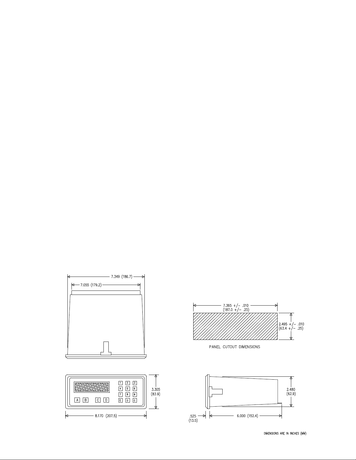
Mounting:
The controller should be located in an area with a clean, dry atmosphere which is relatively free of shock and
vibration. The SP2850-TC is installed in a 7.365” (18mm) wide by 2.495” (63.4mm) high panel cutout. (See
mounting Dimensions) To mount the controller, proceed as follows:
a. Prepare the panel opening.
b. Slip the gasket (provided) over the rear case and slide it forward until it engages the inner surface of the front
bezel.
c. Slide the unit into the panel opening and slide it forward until the panel engages the inner surface of the gasket
at the
front bezel.
d. Install the screws (provided) in the mounting brackets and insert into the mounting holes on top, bottom and
sides of
case.
e. Tighten the screws firmly to attach the bezel to the panel. 3 in. Lb. Of torque must be applied and the bezel
must be
parallel to the panel to maintain NEMA 4 rating.
NOTE: To seal to NEMA 4X specs., supplied gasket must be used and panel cannot flex more than .010”. All 4
clamps must be tightened a min. Of 3 in. Lb. Torque. If panel flex occurs, seal unit with RTV type sealer.
Page 7

Sponsler, Inc.
Model SP2850-TC with MS649
Page 7
DOC#: MN-2850
PRESET
PREWARN
WIRING
AC/DC Connections:
NOTE: Connect power only after other connections are finished. Do not touch the live AC power terminals. The
unit has been designed with an isolated AC input, therefore polarity is not a concern for the AC power. The chassis
is plastic, therefore earth ground is not used. For DC operation, connect +DC to terminal 14 and -DC to terminal 12.
Although the unit is designed to be immune from line or RF interference, the unit is controlled by a microprocessor
and an electrically ‘noisy’ environment could cause operating problems. The input power lines should not be
common to power lines or motors, pumps, contactors, etc.
Four sources of noise can occur:
1) AC power line noise- If the unit cannot be connected to an electrically clean power source, an inductive load
suppressing device (MOV as GE#V130LA1 or Resistor, Capacitor as Paktron # .2uf/220 ohm @400V) can be
installed. Although locating the suppressor across the AC supply at the unit should help, best results are obtained
by connecting the suppressor across the leads of the ‘load’ at the device causing the spikes.
2) Input line noise- The noise is carried on the input and DC ground lines. Make sure the input wires are not run
into the unit in a bundle with power input lines. We recommend using shielded cable. Connect the shield to DC
ground of the unit and ‘earth’ at one point in the circuit preferably at the DC ground terminal of the unit.
3) Output lines- The unit has two open collector outputs and two relay outputs. When these outputs are used to
run external relays or solenoids, spikes can be generated upon activation. This noise can spread through the
instrument causing operating problems. If the source is a DC operated device, a general purpose diode (IN4004)
placed across the solenoid prevents electrical noise spikes. Connect the cathode (banded side) to the more
positive side of the coil. If the source is an AC operated device, use a Resistor, Capacitor or MOV across the coil.
4) DC output supply- Noise can be generated on the DC output supply if it is used to drive inductive loads or if the
current draw exceeds 100mA. Insure that all inductive loads have a diode (such as IN4004) across the coil and that
the current does not exceed 100mA.
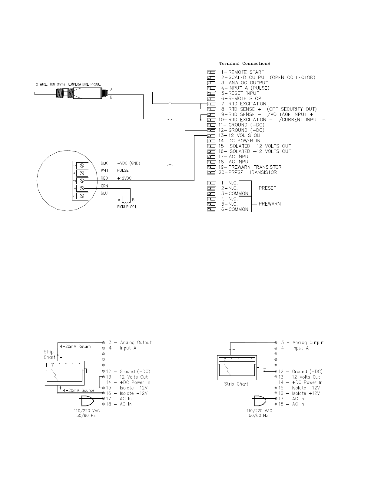
WIRING CONNECTIONS
Terminal Connections:
1 - REMOTE START
2 - SCALED OUTPUT (OPEN COLLECTOR)
3 - ANALOG OUTPUT
4 - INPUT A (PULSE)
5 - RESET INPUT
6 - REMOTE STOP
7 - RTD EXCITATION +
8 - RTD SENSE + (OPT SECURITY OUT)
9 - RTD SENSE - / VOLTAGE INPUT +
10- RTD EXCITATION - / CURRENT I NPUT +
11- GROUND (-DC)
12- GROUND (-DC)
13- 12 VOLTS OUT
14- DC POWER I N
15- ISOLATED -12 VOLTS OUT
16- ISOLATED +12 VOLTS OUT
17- AC INPUT
18- AC INPUT
19- PREWARN TRANSISTOR
20- PRESET TRANSISTOR
1 - N.O.
2 - N.C.
3 - COMMON
4 - N.O.
5 - N.C.
6 – COMMON
Page 8
Sponsler, Inc.
Model SP2850-TC with MS649
Page 8
DOC#: MN-2850
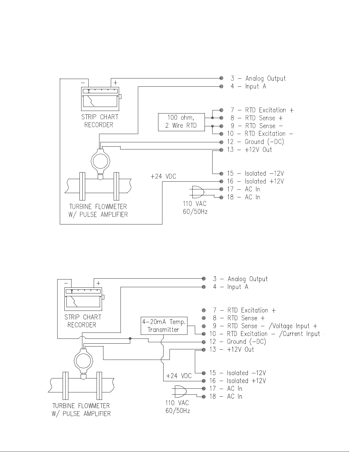
Typical Wiring:
Pulse Input/RTD Input/Current Output
Pulse Input/Analog Input/Voltage Output
Page 9
Sponsler, Inc.
Model SP2850-TC with MS649
Page 9
DOC#: MN-2850
TYPICAL WIRING: SP714 & SP717
ANALOG OUTPUTS
The output on external pin 3 is a 4-20mA, 0-5 VDC, or 0-10 VDC output corresponding to the selected rate
readings. When the output is 4-20mA, a sinking driver generates a linear current across the recorder, PLC,
computer or external meter. When the output is a voltage, the unit generates a positive voltage with respect to
ground (pin 12). In the program set-up mode the user is prompted to `SET LOW’ (4mA rate or 0V rate) and ‘SET
HIGH’ (20mA rate or 5V; 10V rate).
The unit can supply the 24 VDC to power the current loop. Connect Pin 15 to Pin 13. Pin 16 is now +24 VDC with
respect to Pin 12. With Pin 15 connected to Pin 13, connect Pin 16 to the +DC side of the external device and
connect Pin 3 to -DC side of the external device.
CURRENT OUT VOLTAGE OUT
Page 10

Sponsler, Inc.
Model SP2850-TC with MS649
Page 10
DOC#: MN-2850
DEFINITION OF MENU PROMPTS
MENU- This prompt is displayed when the programming menu is entered.
PRESET- This sets the value at which the preset A will drop out (R0, reset to 0 mode). In the ‘SP’ (set to preset
mode) the unit will reset to this Preset value and count down to 0.
PREWARN- This value is the amount before the preset value that the Prewarn relay will drop out. For example: the
Prewarn relay is to drop out 10 counts before the Preset and the Preset is 1234, then set the Prewarn at 10
(not 1224). NOTE: If the Prewarn is larger than the Preset, the warning ‘PREWRONG’ will be displayed.
PRE TYP- (PRESET TYPE): This section of the menu allows the user to choose between ‘EZ PRE’ (easy preset) or
‘STD PRE’ (standard preset).
EZ PRE- (EASY PRESET): See ‘OPERATION USING EZ PRE’ pg.
STD PRE- (STANDARD PRESET): See ‘OPERATION USING STD PRE’ pg.
INHKEY(INHIBIT): Disables front panel START, STOP, MENU, ENT keys.
ENAKEY (ENABLE): Enables front panel START, STOP, MENU, ENT keys.
16 POINT- This section of the menu allows the user to select 16 point variable K-Factor data or linear K-Factor
programming.
16PT- (16 POINT); Enter this section to enter the 16 point setup procedure.
LN- (LINEAR); Enter this section to set up a linear K-Factor.
K-FACTOR- This is a scaling factor that converts the input into engineering units. Example: To total in gallons when
the meter is putting out 100 pulses per gallon, enter 100 for K-Factor.
TEST- When ‘TEST’ is selected, point data can be entered exactly as in selected time entries. However, when the
unit ‘runs’ in Test mode, K-Factor is always 1. ‘Rate’ (R) displays frequency (inputs per second). ‘Counter’ displays
1 count per each unit.
HOURS- When `hours’ is selected, the ratemeter will display units per hour.
MINUTES- When `minutes’ is selected, the ratemeter will display units per minute.
SECONDS- When `seconds’ is selected, the ratemeter will display units per second.
POINT ##- This prompt appears before each of the 16 points to be entered. To exit the 16 point set-up press `CLR’
then `ENTER’.
F#######- This prompt indicates the Frequency for each of the 16 points.
K#######- This prompt indicates the K-Factor for each of the 16 points.
COUNT- This section of the menu is used to set up the counter information.
R0- (RESET TO ZERO): When `R0’ is selected, the counter will reset to 0 (count up) when reset.
SP- (SET TO PRESET); When `SP’ is selected, the unit will reset to preset (count down) when reset.
Page 11

Sponsler, Inc.
Model SP2850-TC with MS649
Page 11
DOC#: MN-2850
DEC LOC- (DECIMAL LOCATION); This sets the decimal location for the counter, preset and prewarn.
CNTENAHI (COUNT ENABLE HI): Temperature/Density high count cutoff.
CNTENALO (CONUT ENABLE LO): Temperature/Density lo count cutoff.
RATE- This section of the menu is used to set up the ratemeter information.
WINDOW- This is the amount of time (02-24 sec.) that the unit will `look’ for valid input data before the rate display
defaults to 0.
SIG FIG- (SIGNIFICANT FIGURE); This sets the number (1-6) of meaningful digits the ratemeter will display.
Example: If 2 is entered, a rate of 723.456 will be displayed as 720.
If 6 is entered, a rate of 723.456 will be displayed as 723.456
WEIGHT- This is a weighted averaging factor (00-99). Higher settings provide more averaging for a more stable
display. Derived from the equation:
(OLD DATA x `WEIGHT’ + NEW DATA)
(`WEIGHT’ + 1)
LOCKOUT- This section of the menu is used to set up the lock code and security time.
SECUR##- This sets the security time (00-99 sec.) Enter 00 to disable the security feature. The security feature
monitors the input loss of data. If the unit is started and doesn’t receive a pulse in the amount of time entered, the
relays will drop out and the display will read `SECURITY’. The unit cannot be restarted until the 4 digit lockout code
is entered.
NOTE: This feature is not available with RTD input.
CODE- This sets the 4 digit lockout code. This code is used to lock and unlock the unit and to return the unit to the
run mode when in `SECURITY’.
OUTCARD- This section of the menu is used to set up the RS232 or RS422 communication information it this
option is installed.
UNIT##- This sets the unit ID number. This number is to be addressed when the unit is to be on line.
PL- (PARALLEL); This sets the unit for a parallel input.
SER- (SERIAL); This sets the unit for a serial input. The unit should always be set for serial, parallel is
disabled.
BAUDRATE- This sets the baudrate of the serial communication.
PARITY- This sets the parity of the serial communication.
ALG OUT- (ANALOG OUT); This section is used to set up the analog output information.
ANLG CT- (ANALOG COUNT); When selected, analog output corresponds to the counter display.
SET LOW- Sets the low value for the analog output. EX: 4mA out is to equal a rate of 10, enter 10.
SET HIGH- Sets the high value for the analog output. EX. 20mA out is to equal a rate of 10,000, enter 10000.
OUTFREQ- (OUTPUT FREQUENCY); This sets the frequency of the scaled pulse output (10, 200, 2000, or 20000
Hz). If the scaled input frequency exceeds the selected output frequency, internal buffers will store up to 10,000
pulses for output at the selected frequencies.
COMP IN- (COMPENSATION INPUT); This section of the menu is used to set up the compensation input
information.
IN TYPE- (INPUT TYPE); This sets the input type (RTD, analog or manual)
RTD- This sets the compensation input for an RTD when selected and jumper options are installed correctly (ref.
Pg.24)
°C °F- Choose between °F or °C for the temperature information.
ANLG RT- (ANALOG RATE); When selected, the analog output corresponds to the rate display.
Page 12

Sponsler, Inc.
Model SP2850-TC with MS649
Page 12
DOC#: MN-2850
4-20mA- This sets the compensation input for 4-20mA input when selected and jumper options are installed
correctly (ref. Pg.24)
0-5V- This sets the compensation input for 0-5V input when selected and jumper options are installed correctly (ref.
Pg.24)
0-10V- This sets the compensation input for 0-10V input when selected and jumper options are installed correctly
(ref. Pg.24)
DN TEMP- (DENSITY or TEMPERATURE); Choose to compensate for density or temperature.
DEFLT DN- (DEFAULT DENSITY); The value entered here will be the density value used in the equations when or
if there is a density error (the density input goes above or below range, signal lost or sensor failure).
DENS LOW- (DENSITY LOW); This sets the low value for the density analog input. EX. If 4mA = .2, ENT .2
DENS HI- (DENSITY HIGH); Sets the high value for the density analog input. EX. If 20mA = 20.8, ENT 20.8
DEFLT T P- (DEFAULT TEMPERATURE); The value entered here will be the temperature value used in the
equations when or if there is a temperature error (the temperature input goes above or below range, signal lost or
sensor failure)
TEMP LOW- (TEMPERATURE LOW); This sets the low value for the temperature analog input. EX. If 4mA = 0,
ENT 0
TEMP HI- (TEMPERATURE HIGH); This sets the high value for the temperature analog input. EX. If 20mA = 100.0,
ENT 100.0
MANUAL- This allows the user to enter in the operating temperature or density when the compensation input is not
used.
ENT DEN- (ENTER DENSITY); When the compensation input is set for manual and density, this prompt allows the
user to enter the density of the liquid at operating conditions.
ENT TEMP- (ENTER TEMPERATURE); When the compensation input is set for manual and temperature, this
prompt allows the user to enter the temperature of the liquid at operating conditions.
FLUID- This section of the programming menu is used to set up the fluid properties.
REF DENS- (REFERENCE DENSITY); Allows the user to enter the reference density of the liquid.
REF TEMP- (REFERENCE TEMPERATURE); Allows the user to enter the reference temperature of the liquid.
EXP COEF- (EXPANSION COEFFICIENT); This allows the user to enter the thermal coefficient of expansion for
the liquid. The value must be entered in straight decimal notation. EX. If the coefficient of expansion is 115 X 10
then enter 0.000115.
FLOW EQ- (FLOW EQUATIONS); This section of the programming menu is used to set up the type of flow
equation used.
MASS- When this is selected the flow equation will be calculated for mass (weight i.e. pounds, Kgrams, etc.)
COR VOL- (CORRECTED VOLUME); When this is selected the flow equation will be calculated for corrected
volume (area i.e. gallons, liters, etc.)
-6
,
Page 13

Sponsler, Inc.
Model SP2850-TC with MS649
Page 13
DOC#: MN-2850
ERROR MESSAGES
While programming and running the unit, various error messages may be displayed. The messages signal when a
programming or operating error has occurred. In some cases the error messages will be displayed until the error is
corrected.
PROGRAMMING ERRORS
PREWRONG: Will be displayed when the Prewarn value is greater than the Preset value. Re-enter the Prewarn
and Preset values correctly to clear the message.
HIGH<LOW: Will be displayed if the analog out `HIGH’ value is less than or equal to the `LOW’ value. Re-enter the
High and Low values correctly to continue programming.
TMPWRONG: Will be displayed if the temperature ‘HIGH’ value is less than the `LOW’ value. Re-enter the High
and Low values to continue programming.
DENWRONG: Will be displayed if the density `HIGH’ value is less than the `LOW’ value. Re-enter the High and
Low values correctly to continue programming.
OPERATING ERRORS
SECURITY: Displays when the unit enters the security mode. The security feature monitors the input as described
in the ‘Definition of Menu Prompts’ (see SECUR##). To get the unit out of security, enter the 4 digit lockout code.
Be sure to check the input wiring and sending device to find why no pulses were received. NOTE: A Security Output
is available on units using current or voltage for compensation input. This output isn’t available on units using RTD
because they share a common terminal on the terminal block (Pin 8). The Security Output is an NPN (sinking)
transistor output internally pulled up to +5 VDC. This output will turn on when the unit enters security and remain on
until the security warning is cleared.
ERROR TP: Displays when the temperature input is defective or out of range. (I.e. below 4mA or above 20mA).
The unit uses the default temperature value when there is a temperature error. Pressing the `CLR’ button will clear
the message, but the unit will continue to use the default temperature value until the error is corrected.
ERROR DN: Displays when the density input is defective or out of range. (I.e. below 4mA or above 20mA). The
unit uses the default density value when there is a density error. Pressing the `CLR’ button will clear the message,
but the unit will continue to use the default density value until the error is corrected.
Page 14

Sponsler, Inc.
Model SP2850-TC with MS649
Page 14
DOC#: MN-2850
PROGRAMMING FLOWCHART
* SECURITY output is not available with RTD input.
** Appropriate jumper options must be installed. Refer to pg.
+ REF TEMP and EXP COEF menu selections will not appear if COMP IN is set for DN (density).
Page 15

Sponsler, Inc.
Model SP2850-TC with MS649
Page 15
DOC#: MN-2850
Press
Display
D
MENU flashes then PRESET ↓
ENT
# # # # # # # # (Existing Preset Flashes)
CLR
0 Flashes
1 4 2 7 8
(as an example)
1 4 2 7 8 Flashes
ENT
(Preset Entered)
RUN MODE
Press
Display
MENU Flashes the PRESET ↓
D
PREWARN ↓
ENT
# # # # # # # # (Existing Prewarn Flashes)
CLR
0 Flashes
4 8 (as an example)
4 8 Flashes
ENT
(Prewarn Entered)
RUN MODE
(Reference page for descriptions of the 2 operating options.)
Press
Display
D
MENU Flashes the PRESET ↓
D
until
PRE TYP ↓
EZ PRE ↓ (Existing Preset Type)
D
STD PRE ↓
(Press
D
to go to EZ PRE ↓)
ENT
INHKEY ↓
(Press
D
to go to ENAKEY↓)
ENT
(to select displayed option)
RUN MODE
Press
Display
D
MENU Flashes then PRESET ↓
D
until
16 POINT↓
ENT
LN↓ 16PT↓ (LN: Linear 16PT: 16 point)
(Press
B
for linear)
ENT
SECONDS, MINUTES, or HOURS (Rate Timebase)
SETUP PROCEDURES
NOTE: Start here and finish to the end. If you make a mistake, press ENT until you reach the beginning of that
step.
STEP 1: Setting the Preset
STEP 2: Setting the Prewarn
D
STEP 3: Setting Preset Type.
ENT
STEP 4: Setting 16 Point Option for Linear Input
Page 16

Sponsler, Inc.
Model SP2850-TC with MS649
Page 16
DOC#: MN-2850
(Press
D
to display desired timebase)
ENT
(selects displayed options)
K-FACTOR (Flashes, followed by existing K-Factor)
CLR
0 Flashes
1 1 D 6 8
(as an example)
11.68 Flashes
(Press
D
for decimal)
ENT
RUN MODE
per each input.
Press
Display
D
MENU Flashes then PRESET ↓
D
until
16POINT ↓
ENT
LN↓ 16PT↓ (LN: Linear 16PT: 16 point)
(Press
D
for 16 point)
ENT
MINUTES ↓
D
HOURS ↓
D
TEST ↓
D
SECONDS ↓
(Press
D
to go to minutes)
ENT
(selects displayed option)
POINT 00 (Enter point 00 to go to run mode)
1
(selects point 1)
POINT 01 (Key in point desired)
ENT
F # # (Shows frequency in memory)
CLR
F 0
1 0 0
(as an example)
F 100 (Frequency for point 1 is 100)
ENT
K # # (Shows K-Factor in memory)
CLR
K 0
1 0 0
(as an example)
K 100 (K-Factor for point 1 is 100)
2 POINT 02 (Enter point data as desired)
(Repeat through 16 points)
CLR
POINT 00 (Enter point 00 to exit setup)
ENT
RUN MODE
Setting 16 Point Option for Non-linear Input: Reference `16 Point Linearization Option”
NOTE: If TEST is entered, point data can be entered exactly as in selected time entries. However, when the unit
`runs’ in Test Mode `K-Factor’ is always 1. `Rate’ (R) displays frequency (inputs per sec.). Counter displays 1 count
Page 17

Sponsler, Inc.
Model SP2850-TC with MS649
Page 17
DOC#: MN-2850
The rate can be displayed in 3 ways: `SECONDS_’, `MINUTES_’, or `HOURS_’. If `SECONDS_’ is selected the unit
displays the `base’ rate calculated from the incoming frequency and the `specific K-Factor’. If `MINUTES_’ is selected, the rate
displayed is 60 times the `base’ rate. If `HOURS_’ is selected, the rate displayed is 3600 times the `base’ rate.
NOTE A:
Unit defaults `0’ K-Factor to K-Factor of `1’ since it is impossible to divide by `0’
the decimal)
16-POINT LINEARIZATION OPTION
Description:
The 16 point K-Factor option allows the user to dial in from 3 to 16 different frequency points (inputs per second) and different KFactor dividers from 0.0001 to 99999999 for each of these frequencies.
The 16 point unit determines the incoming frequency and calculates a K-Factor line slope from the two closest data points that
had been entered. The `specific K-Factor’ is then proportionally interpolated using 8-position floating math. This K-Factor is
applied to all inputs until the next frequency calculation, usually 1 second later. If a `0’ frequency is entered in `point 1’ the `point
1’ K-Factor will be applied to all inputs received before the first frequency calculation.
POINT DATA FORMATTING
Each Frequency/K-Factor data entry is assigned a point number. Any point number may be selected to view and/or change the
Frequency/K-Factor data. The frequencies must be entered in ascending order. `BAD FREQ’ will flash when exiting the set up
mode if there is a sequence error. The unit will then display the sequence error point # so that corrections can be made.
NOTE B:
NOTE C:
NOTE D:
NOTE E:
Example:
`Point 01’ will be the `low shut-off’ frequency. Below this frequency no rate will be displayed nor count
recorded. Point 01 should be assigned a frequency of `0’ with a K-Factor for lowest flow especially if
very slow flow is to be counted.
The entry for a frequency of `0’ for `point 03’ or above will tell the unit to continue the K-Factor slope line
calculated from the two previous Frequency/K-Factor points and ignore any higher point data. If a fixed
K-Factor id desired, select LN in 160 Point setup.
K-Factors are always positive numbers. To avoid undesired K-Factors projected around `0’ K-Factors,
insure that a positive K-Factor is assigned for the highest used frequency.
The decimal in the `TOTAL’ is a dummy. The K-Factor should be calculated to show all numbers as if
there were no decimal and then decimal added under DEC LOC section of COUNT MENU. The KFactor must be divided by a factor of ten for each digit to the right of the decimal in the displayed total.
A meter gives 133.4 pulses per gallon and it is desired to display in 1/100 gallons. Move K-Factor
decimal two places to the left (1.334) and key in 3 under DEC LOC menu. (2 digits display to the right of
Page 18

Sponsler, Inc.
Model SP2850-TC with MS649
Page 18
DOC#: MN-2850
Press `D’ until `16 POINT’ appears on display. Press `ENT’. Press `D’ to step through options:
(fixed K-Factor of `1’) and display frequency (rate per second) of incoming signal. (See TEST MODE)
A specific `TEST’ mode can be selected to help set up the points and K-Factors. If `TEST’ is selected the RATE (`R’ display) will
D) Record this frequency and K-Factor for later entry into point 1 or point 2. (See NOTE B, Point Data Formatting to
K-Factor data. A minimum of 3 points and a maximum of 16 points must be entered.
DATA ENTRY FOR 16-POINT
SECONDS (Scaled rate per second selected)
MINUTES (Scaled rate per minute selected)
HOURS (Scaled rate per hour selected)
TEST (Test mode-rate per second with 1 count for each input (fixed K-Factor of 1) selected)
Press `ENT’ when desired option is displayed
Point 00 will appear on the display. Press `ENT’ to exit the set up and go to run mode or key in a point number from
1 to 16 and press `ENT’
`K’ will flash with present K-Factor for that point. To change the K-Factor, press `CLR’ and key in desired K-Factor,
Press `ENT’.
Continue to step through the POINT numbers to view or change data. If a frequency of `0’ is entered in POINT 3 or
above, the unit will ignore data above that point number. A K-Factor generated from the line slope of the 2 previous
POINT entries will be applied to higher frequencies.
Exit `point set’ routine by setting the POINT 00 and press `ENT’.
Unit will go to run mode. `BAD FREQ’ will flash when exiting the set up mode if there is a sequence error. The unit
will then display the sequence error point # so that corrections can be made.
If `TEST’ is selected, point data can be entered into memory but when running, unit will add one count per each unit
TEST MODE
show the frequency (pulses per second) of the incoming signal. The TOTAL section will accumulate one count for each
incoming pulse.
TEST MODE K-FACTOR CALCULATION
To calculate the K-Factors for flow meters with pulse transmitters:
A) Set the 16 point units to `TEST’ and ENT point 00 to go to run mode.
B) At the lowest desired flow rate, reset the counter and let the unit count the incoming signal while the rate displayed is
recorded.
C) Interrupt the input signal when the known tested volume has gone through the flow meter. Switch to count display
and read the number of counts that came in from the known volume as displayed on the unit. Divide the counts by the
volume that past through the meter to determine the number of counts for 1 unit of measure; gallon, cubic foot, etc.
determine if data should be entered in point 1 or 2).
E) Assign ascending point numbers to correspondingly ascending frequencies when recording frequency/
Page 19

Sponsler, Inc.
Model SP2850-TC with MS649
Page 19
DOC#: MN-2850
Press
Display
D
MENU Flashes then PRESET ↓
D
until
COUNT ↓
ENT
R0 SP↓
(RO Reset to 0 `ADD’ or SP: Set to Preset to
`SUBTRACT’)
B
or D to move cursor (_) to the desired option
Selects R0 or SP
ENT
(Selection Entered)
* DEC LOC (Decimal Location)
Press the number of the digit that will display to the left of
Decimal moves to that location
third digit 3.21)
ENT
(Decimal location entered)
CNTENALO ↓
**WAIT**
# # (Existing window value)
CLR
0
3 2 0 C
(As an example)
-320
ENT
CNTENAHI ↓
**WAIT**
# # (Existing window value)
CLR
0
2 9 2 C
(As an example)
-292
ENT
RUN MODE
*NOTE: The decimal displayed in the `TOTAL’ and `GRAND TOTAL is a dummy. The K-Factor must be divided by a
decimal. The K-Factor must be divided by 100 for correct totalization and rate indication.
Press
Display
D
MENU Flashes to PRESET ↓
D
until
RATE ↓
ENT
WINDOW # # (Existing Window Value)
CLR
WINDOW 00
4
Example Only.
WINDOW 04
wait for an input pulse before displaying 0 rate.
ENT
(Window Entered)
SIGFIG # # (Existing Value)
SETUP PROCEDURES CONTINUED
STEP 5: Setting the Counter
the decimal.
(Example: 3, the decimal will display to the right of the
factor of ten for each digit to the right of the decimal. Example: Decimal Location 3 displays 2 digits to the right of the
STEP 6: Setting the Ratemeter
Key in the desired time (02 to 24 sec.) that the unit will
Page 20

Sponsler, Inc.
Model SP2850-TC with MS649
Page 20
DOC#: MN-2850
CLR
SIGFIG 00
6
Example Only.
SIGFIG 06
Key in the desired number of digits for rate display
(SIG FIG indicated how many meaningful digits are shown; trailing zeroes are inserted if necessary)
ENT
(SIG FIG Entered)
WEIGHT # # (Existing Weight Value)
CLR
WEIGHT 00
6 WEIGHT 06
ENT
(Weight Entered)
RUN MODE
Press
Display
D
MENU Flashes to PRESET ↓
D
until
LOCKOUT ↓
ENT
SECUR # # (Existing Value)
SECUR (Security) is the amount of time (seconds) that the unit will `look’ for valid input pulses. If no pulses are
This feature is not available with RTD input.
CLR
SECUR 00
4
(As an example)
SECUR 04
ENT
((SECUR Entered)
CODE Followed by Flashing Code Number
CLR
0
1 1 1 1
(As an example)
1 1 1 1 (Flashing)
This is the code used to lock/unlock unit. RECORD FOR LATER USE.
ENT
(CODE Entered)
RUN MODE
Press
Display
D
MENU Flashes to PRESET ↓
D
until
OUTCARD
ENT
(Unit ID number. Can be any number from 1 to 15)
UNIT # # (Existing Value)
CLR
UNIT 00
1
(As an example)
UNIT 01
ENT
(Unit number entered)
PL↓ SER↓ *
ENT
BAUDRATE (Flashes followed by last baudrate used)
300 ↓
STEP 7: Setting Lockout Code
received in the programmed amount of time, the relays will drop out and the unit will display `SECURITY’. The four
digit lockout code must be entered to return to normal operation. Note: Entering 00 will disable the security feature.
STEP 8: Setting the Communication Out Card (Skip if RS232/422 option is not installed)
Page 21

Sponsler, Inc.
Model SP2850-TC with MS649
Page 21
DOC#: MN-2850
600 ↓
D
1200 ↓
D
2400 ↓
4800 ↓
D
9600 ↓
(Press
D
to go to 300 ↓)
ENT
PARITY (Flashes, then last parity used)
D
EVEN ↓
D
ODD ↓
D
MARK ↓
D
SPACE ↓ (Press
D
to go to EVEN ↓)
ENT
RUN MODE
*Unit should always be `SER’, `PL’ is disabled.
Press
Display
D
MENU Flashes then PRESET ↓
ALG OUT ↓
ENT
ANLG RT (Analog Output for Rate)
D
(Press
D
to toggle between selections)
ANLG CT (Analog Output for Count)
ENT
(To select displayed option)
SET LOW (Flashes to Last Value Stored)
CLR
0 (Flashing)
1 D 2 4
(As an example)
1.24 (Flashing)
(Press
D
for decimal) In this example 1.24 = 4mA
ENT
(Low set at 1.24)
SET HIGH (Flashes to Last Value Stored)
CLR
0 (Flashing)
1 0 0 D 0
(As an example)
100.0 (Flashing)
(Press
D
for decimal) In this example 100.0 = 20mA
ENT
(High set at 100.0)
RUN MODE
Press
Display
D
MENU Flashes then PRESET ↓
D
until
OUTFREQ ↓
D
D
STEP 9: Setting the Analog Output
D until
STEP 10: Setting Output Frequency
Page 22

Sponsler, Inc.
Model SP2850-TC with MS649
Page 22
DOC#: MN-2850
20000 ↓ (Displays last selection)
D
2000 ↓
D
200 ↓
D
10 ↓ (Press
D
to go to 20000 ↓)
ENT
(To select displayed option)
RUN MODE
NOTE: When RTD input is desired, the RTD `R’ input option must be ordered or jumper changes made. See jumper
option on page 24.
Press
Display
D
MENU Flashes then PRESET ↓
D
COMP IN ↓
ENT
IN TYPE (Flashes to last type entered)
D
4-20MA ↓
D
0-5V ↓
0-10V ↓
D
MANUAL ↓
D
RTD ↓ (Press
D
to go to 4-20MA ↓)
ENT
(When RTD is displayed)
°C↓ °F°↓ (Press
B
for °C, Press
D
for °F)
ENT
DEFLT TP (Followed by existing value)
CLR
0 (Flashing)
1 D 2 4
(As an example)
1.24 (Flashing)
(Press
D
for decimal)
(Press
C
to change sign (+ or - displayed at the left of the display)
ENT
RUN MODE
NOTE: If an analog input (mA or V) is desired, the unit must be ordered without the `R’ (RTD) option or jumper
changes made. See `Jumper Options’ page 24.
Press
Display
D
MENU Flashes to PRESET ↓
D
until
COMP IN ↓
ENT
IN TYPE (Flashes to last type entered)
RTD ↓
ENT
STEP 11: Setting the Compensation Input for RTD
D
STEP 11A: Setting Compensation Input for Analog (Temperature)
Page 23

Sponsler, Inc.
Model SP2850-TC with MS649
Page 23
DOC#: MN-2850
4-20MA ↓
D
0-5V ↓
D
0-10V ↓
D
MANUAL ↓ (Press
D
to go to RTD ↓)
ENT
(Selects displayed option)
DN↓ TEMP↓
(Press
B
for DN-Density
D
for TEMP-temperature)
ENT
(When TEMP is selected)
(Press
B
for °C, press
D
for °F)
ENT
DEFLT TP (Followed by existing value)
CLR
0 (Flashing)
1 D 2 4
(As an example)
1.24 (Flashing)
(Press
D
for decimal, press
C
to change sign, i.e. + or -)
ENT
TEMP LOW (Followed by existing value)
CLR
0 (Flashing)
1 0 D 0
(As an example)
10.0 (Flashing)
(Press
D
for decimal, press
C
to change sign, i.e. + or -)
ENT
TEMP HIGH (Followed by existing value)
CLR
0 (Flashing)
1 0 0 D 0
(As an example)
100.0 (Flashing)
(Press
D
for decimal, press
C
to change sign, i.e. + or -)
ENT
RUN MODE
changes made. See `Jumper Options’ page 24.
Press
Display
D
MENU Flashes to PRESET ↓
D
until
COMP IN ↓
ENT
IN TYPE (Flashes to last type entered)
RTD ↓
D
4-20MA ↓
0-5V ↓
D
0-10V ↓
D
°C↓ °F↓
STEP 11B: Setting Compens ation Input for An alog (Density)
NOTE: If an analog input (mA or V) is desired, the unit must be ordered without the `R’ (RTD) option or jumper
D
Page 24

Sponsler, Inc.
Model SP2850-TC with MS649
Page 24
DOC#: MN-2850
MANUAL ↓ (Press
to go to RTD ↓)
ENT
(Selects displayed option)
DN ↓ TEMP ↓ (
(Press
B
for DN-Density
D
for TEMP-Temperature)
ENT
(When DN is selected)
DEFLT DN (Followed by existing value)
CLR
0 (Flashing)
1 D 2 4
(As an example)
1.24 (Flashing)
(Press
D
for decimal)
ENT
DENS LOW (Followed by existing value)
CLR
0 (Flashing)
1 0 D 0
(As an example)
10.0 (Flashing)
(Press
D
for decimal)
ENT
DENS HI (Followed by existing value)
CLR
0 (Flashing)
1 0 0 D 0
(As an example)
100.0 (Flashing)
(Press
D
for decimal)
ENT
RUN MODE
Press
Display
D
MENU Flashes the PRESET ↓
D
until
COMP IN ↓
ENT
IN TYPE (Flashes to last type entered)
RTD ↓
D
4-20MA ↓
D
0-5V ↓
D
0-10V ↓
D
MANUAL ↓ (Press
D
to go to RTD ↓)
ENT
(When MANUAL is displayed)
DN ↓ TEMP ↓
(Press
B
for DN-Density;
D
for TEMP-temperature)
(Press
for °C, press
for °F)
ENT
ENT TEMP (Followed by existing value)
CLR
0 (Flashing)
D
D
STEP 11C: Setting Compens ation Input for Manual (Temperature)
ENT (When TEMP is selected)
°C ↓ °F ↓
B
D
Page 25

Sponsler, Inc.
Model SP2850-TC with MS649
Page 25
DOC#: MN-2850
1 0 0 D 0
(As an example)
100.0 (Flashing)
(Press
D
for decimal, press
C
to change sign, i.e. + or -)
ENT
RUN MODE
Press
Display
D
MENU Flashes the PRESET ↓
COMP IN ↓
ENT
IN TYPE (Flashes to last type entered)
RTD ↓
D
4-20MA ↓
D
0-5V ↓
0-10V ↓
D
MANUAL ↓ (Press
D
to go to RTD ↓)
ENT
(When MANUAL is displayed)
DN ↓ TEMP ↓
(Press
B
for DN-Density;
D
for TEMP-Temperature
ENT
(When DN is selected)
ENT DN (Followed by existing value)
CLR
0 (Flashing)
1 2 D 4
(As an example)
12.4 (Flashing)
(Press
D
for decimal)
ENT
RUN MODE
Press
Display
D
MENU Flashes then PRESET ↓
D
until
FLUID ↓
ENT
REF DENS (Followed by existing value)
NOTE: If the compensation input is set for temperature and the flow equation is set for corrected volume, the
enter one (1). Realize that when one (1) is entered the density displayed in the run mode will be incorrect.
CLR
0 (Flashing)
6 1 D 2
(As an example)
61.2 (Flashing)
(Press
D
for decimal)
ENT
*REF TEMP (Followed by existing value)
STEP 11D: Setting the Compe n sation Input for Manual (Density)
D until
D
STEP 12: Setting the Fluid Properties
reference density needs to be entered only for the density in the run mode. If the reference density is not known,
Page 26

Sponsler, Inc.
Model SP2850-TC with MS649
Page 26
DOC#: MN-2850
CLR
0 (Flashing)
1 0 0 D 0
(As an example)
100.0 (Flashes)
(Press
D
for decimal, press
C
to change sign, i.e. + or -)
ENT
*EXP COEF (Followed by existing value)
CLR
0 (Flashing)
D 0 0 0 0 0 1
(As an example)
.000001 (Flashing)
(Press
D
for decimal)
ENT
RUN MODE
* These menu selections will not appear if COMP IN is set for density.
Press
Display
D
MENU Flashes the PRESET↓
D
until
FLOW EQ ↓
ENT
MASS (Last equation selected)
D
(Press
D
to toggle between MASS & CORR VOL)
COR VOL
ENT
(Selects displayed option)
RUN MODE
STEP 13: Setting the Flow Equati o n s
Page 27

Sponsler, Inc.
Model SP2850-TC with MS649
Page 27
DOC#: MN-2850
PROBLEM
POSSIBLE CAUSES
SOLUTIONS
Power is applied but the display
1. AC or DC power wiring is incorrect.
1. Recheck power wiring.
3. Call factory for RMA.
Unit works but occasionally the
counts.
Line noise is effecting the processor
Use a different power supply or install
Rate is erratic or greatly
fluctuating.
Input pulse frequency is fluctuating.
Increase the `WEIGHT’ value to
average or dampen the rate display.
Unit displaying `DATALOST’.
Pulse input is faster than scaled pulse
output setting.
Increase the `OUTFREQ’ value.
Unit displaying `PREWRONG’.
Preset value is larger than the
Prewarn value.
Recheck Preset and Prewarn values.
(See Error Messages)
Unit displaying `SECURITY’.
1. Unit was started and no pulses
2. Defective flowmeter.
Recheck input wiring, sending device
Messages).
Unit displaying `ERROR TP’.
1. Temperature input is out of range.
2. Defective temperature sensor.
Recheck temperature input wiring and
Unit displaying `ERROR DN’
The density input is out of range.
(i.e. below 4mA or above 20mA)
Recheck density input wiring and
sending device (See Error Messages).
K-Factor
gallon
pulses
ft3
pulses
liter
pulses
M3
pulses
gallon
ft3
liter
M3
Mass Display
lbs
lbs.
Kg.
Kg.
Volume Display
gallon
ft3
liter
M3
Volume Correction Factor (VCF): VCF = 1 - [Coefficient of Expansion X (T
flow
- T
ref
)]
Density: Density = Reference Density C VCF (where: Density is in units of mass per unit volume)
Totalizer:
Corrected Volume Total =
(Input Pulses X VCF)
K-Factor
Mass Total =
(Input Pulses X Density)
K-Factor
Ratemeter: Corrective Volume Rate=
(Frequency X VCF)
K-Factor
Mass Total =
(Frequency X Density)
K-Factor
(Where the various time bases for rate are implied in the rate K-Factor)
TROUBLESHOOTING GUIDE
does not light.
2. Excessive current draw or short on
12 volt output.
3. Damaged unit.
2. Recheck output wiring and insure
that all peripheral devices powered
by the 12 volt output do not exceed
a 100mA current draw.
display freezes or displays erratic
due to a current spike or surge.
were received.
(I.e. below -200°C or above 850°C)
a surge suppressor.
and `SECUR’ time value (See Error
sending device. (See Error Messages)
UNITS OF MEASURE TABLE
Compatible units of measure must be used when entering data and when calculating the coefficient of expansion.
Acceptable combinations for the units of entry include:
Table 1
Ref Density
lbs.
lbs
Kg.
EQUATIONS
Kg.
Page 28

Sponsler, Inc.
Model SP2850-TC with MS649
Page 28
DOC#: MN-2850
Density of fluid =
(Specific Gravity of fluid) X (Density of Water)
Expansion Coef.=
(Ref. Density - Second Density) / Ref. Density
Secondary Temperature - Ref. Temperature
CALCULATING EXPANSION COEFFICIENT
Given:
The liquid density is a function of the flowing temperature for many fluids. This unit solves an equation which
represents this physical property of the fluid.
The information which the unit uses to describe the fluid is entered by the user in the following variables:
Reference Temperature, Reference Density, Expansion Coefficient.
This information is available for many fluids in one or more of the following forms:
Fluid Specific Gravity vs. Temp. Table
Specific Gravity vs. Temp. Graph
Fluid Density vs. Temp. Table
Fluid Density vs. Temp. Graph
Begin by obtaining one of the fluid properties for the fluid you are using from available manufacturers information or
Engineering Handbooks. In some cases this information is listed on the Material Safety Datasheet for the fluid.
Two temperature-Density pairs will be required to compute the temperature coefficient.
The reference temperature is simply chosen by the user. Common reference temperatures are 60°F or 15°C.
However, for cryogenic fluids, the normal boiling point may also be used. In some cases the fluid data may list
properties at 100°F, this temperature may also be used as the reference temperature.
The reference temperature should be chosen so that it is in the application temperature range. I.e. application
temperature range- 10 to 120°F, reference temperature of 60°F chosen.
Enter the reference temperature at this point.
The reference density must be represented in terms of mass units desired with respect to the volume units
corresponding to the flowmeter’s K-Factor. I.e. If readout in pounds is desired, and the K-Factor is entered for
pulses/gallon, the density must be entered in units of pounds/gallon.
Equation 1
4
Table 1 lists a number of K-Factor/Mass readout units. If your temperature, fluid density or specific gravity is in units
other than those required, you must convert them before entering. Given the Ref. Temp., Ref. Dens., Second
Temp. And Second Dens., calculate the expansion of coefficient as follows:
Equation 2
You are now ready to enter these parameters describing the fluid into the unit.
Page 29

Sponsler, Inc.
Model SP2850-TC with MS649
Page 29
DOC#: MN-2850
R44
Analog output 0 adjust
R45
Analog ouput SPAN adjust
R8
0-10V out
=
47.5K ohm 1%
0-5 V out
=
22.1K ohm 1%
MENU ITEM
SETTINGS
RATE
K-Factor = 1, Window = 2, Sig Fig = 6, weight = 0
ALG OUT
Alg Rate, Set Low = 0, Set Hi = Frequency selected above, i.e. 5000 or 10000
COMP IN
In Type = Manual, Temp., °F, Ent Temp. = 60
FLUID
Ref Dens = 1, Ref Temp = 60, Exp Coef = 0
FLOW EQ
Cor Vol
3
-
Analog Output
Apply signal and connect Amp Meter
adjust R44 to read low voltage.)
Common
Signal
+24 VDC
Amp Meter
CALIBRATION
NOTE: All units are calibrated and jumper options set for the required operations at the factory prior to shipment.
The following procedures should be used only if operating requirements have changed. Calibration should only be
attempted by someone who has the equipment to generate a very accurate frequency signal and who has the
training to open the unit and work with grounded equipment necessary to protect the static sensitive CMOS circuitry.
REMOVING THE CASE
To install or change the input or data interface cards, the case must be removed. Before opening case, remove all
power. CMOS logic is used. Use standard precautions against damage by static discharge. If the unit has a data
interface option RS232/422/422M), two screws in the back, designed to secure the top left connector, may have to
be removed. Next remove the six (6) flat head 4-40x1/4” screws behind the panel and lift off the panel/lens
assembly. Slide the main board display out the front of the case. Once modifications are made, reverse the
procedure to re-assemble the unit, insuring that the main board is in the track. The six (6) screws that hold the
panel must be tight to seal the rubber keypad panel assembly, approximately 0.6 in” lb. Torque.
OUTPUT ADJUST
ANALOG OUT CALIBRATION
To calibrate the analog output, you need: 1-Signal Generator (5 kHz or 10 kHz +/- 1Hz),1-Amp Meter (Volt Meter for
Voltage). After the case is removed (see above), power the unit and make the following selections:
Frequency Generator
110/220 VAC
50/60 Hz
4
12
13
15
16
17
18
-
Input A
-
Ground (-DC)
-
+12V out
-
Isolated -12V
-
Isolated +12V
-
AC In
-
AC In
as shown. Adjust R45 until output
reads 20.0mA. Remove signal and
adjust R44 until output reads 4.0mA.
Re-apply signal and adjust R45 until
output reads 20.0mA. Repeat 3 to 4
times with and without signal until both
high (20mA) and low (4mA) are stable.
(To calibrate for voltage, place volt
meter between pins 3 (+) and 12 (-).
Apply high voltage, remove signal,
Page 30

Sponsler, Inc.
Model SP2850-TC with MS649
Page 30
DOC#: MN-2850
Jumper
Connections
Function
Jumper
Connections
Function
Note: 4-20mA input is available regardless of the jumper positions of J2 and J3.
JUMPER OPTIONS
J1
J1
J2
J2
J3
J3
1 to 2
2 to 3
1 to 2
2 to 3
1 to 2
2 to 3
High Pulse Speed Input 10khz Max.
Low Pulse Speed Input 40Hz Max.
Compensation Input For RTD
Enables Security Output (not avai l abl e w/ RTD)
Compensation Input for RTD
Compensation Input for V ol t age
J4
J4
J5
J5
1 to 2
2 to 3
1 to 2
2 to 3
Sets Analog Out for 4-20mA
Sets Analog Out for Voltage
High Level Pulse Input (4-30VDC)
Low Level Pulse Input (30mV)
Page 31

Page 32

©2009
Pub. No. MN-2850-R1
(09/09)
 Loading...