

Page 1
Installation and Parts Manual
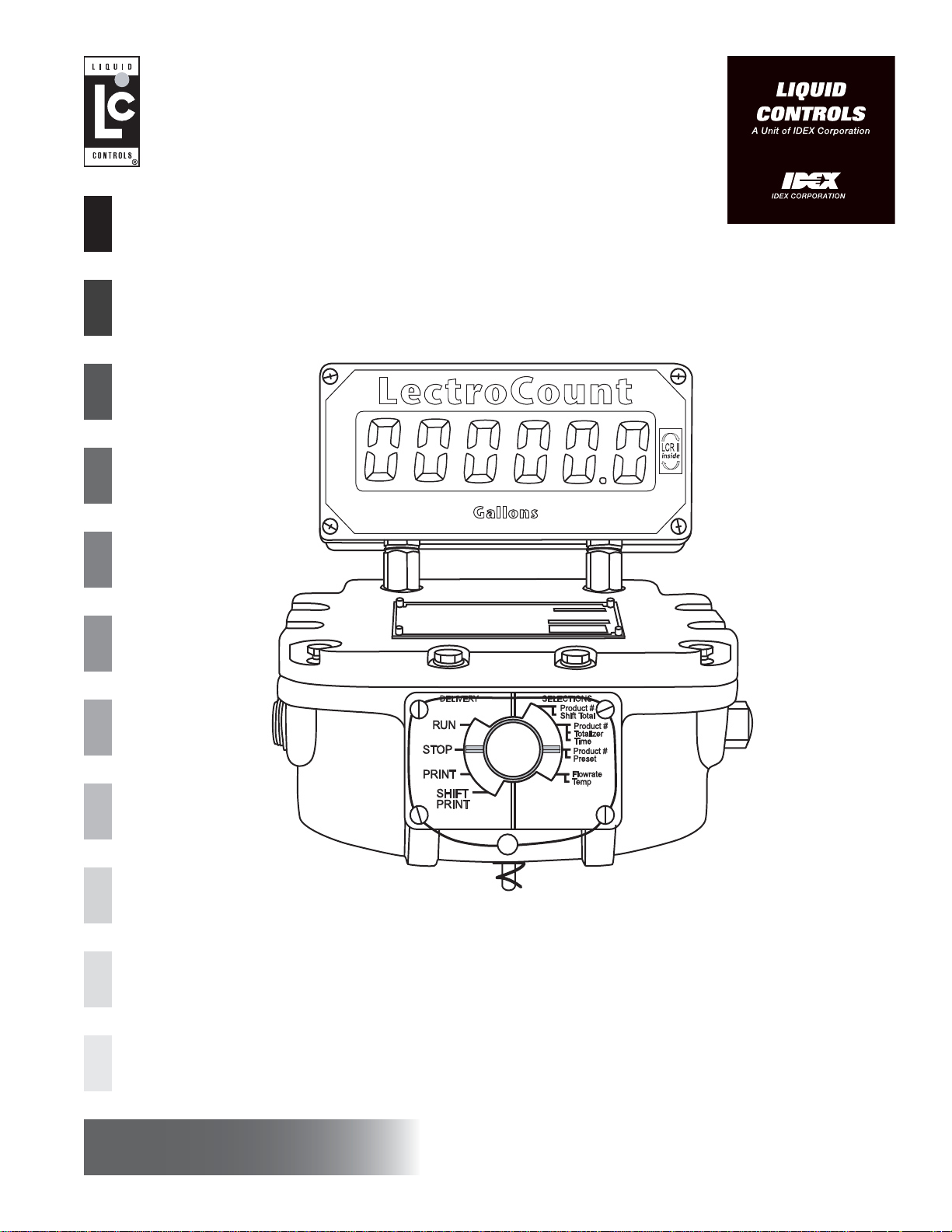
LectroCount LCR
Installation: EM100-20
www.lcmeter.com
Page 2

Table of Contents
!!
!!
!
WARNING WARNING
WARNING WARNING
WARNING
• Before using this product, read and understand the instructions.
• Save these instructions for future reference.
• All work must be performed by qualified personnel trained in the proper application, installation, and
maintenance of equipment and/or systems in accordance with all applicable codes and ordinances.
• Failure to follow the instructions set forth in this puclication could result in property damage, personal injury,
or death from fire and/or explosion, or other hazards that may be associated with this type of equipment.
Description Page Number
Sytstem Overview ........................................................................ 3
Installation Overview .................................................................... 4
Specifications ............................................................................... 5
Regulatory Specifications ............................................................ 6
Parts Requirements ..................................................................... 7
LCR Register Mounting................................................................ 8
Valve Installation .......................................................................... 9
Wiring the LCR ............................................................................. 11
Guidelines for Environmental Sealing .......................................... 16
System Startup............................................................................. 17
Wiring Schematic ......................................................................... 19
Wire Connection Tables ............................................................... 21
Illustrated Parts Breakdown ......................................................... 23
Publication Updates and Translations
The most current English versions of all Liquid Controls publications are available on our website, www.lcmeter.com.
It is the responsibility of the Local Distributor to provide the most current version of LC Manuals, Instructions, and
Specification Sheets in the required language of the country, or the language of the end user to which the products are
shipping . If there are questions about the language of any LC Manuals, Instructions, or Specification Sheets, please
contact your Local Distributor.
2
Page 3

Sytstem Overview
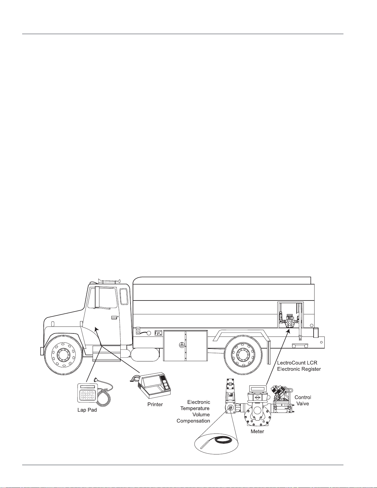
General
The LectroCount LCR is an electronic meter register that
can be used to calibrate a flow meter, control a security
valve, output delivery information via an LCD display and
printer, and, optionally, perform electronic temperature
volume compensation. The LCR receives its flow input
signal from either an external pulser, a meter output, or
an internally mounted quadrature pulser that is
mechanically connected to the flow meter. LCR is housed
in a weather and explosion proof enclosure that can be
mounted directly atop many common positive
displacement meters. Alternatively, the LCR may be
mounted remotely from meters utilizing external pulsers.
A backlit remote electronic counter with a six digit display
on top of the LCR housing provides a real time readout
of product delivered.
Operation
The LCR can be operated as a stand-alone system, as a
stand-alone system with electronic presetting, and as a
slave to a host controller such as a hand held computer,
process controller, or vehicle mounted data terminal. It
can be used in mobile and fixed installations. When
installed with the proper system accessories the LCR
can be used for Weights & Measures approved custody
transfer transactions.
Outputs
Information from the LCR can be output via an RS-232
printer port, RS-485 or RS-232 communication port, a
scaled pulse output,and a counter output.
Installation
This manual describes the installation and operation of
the LCR and its optional accessories. Read this entire
manual before beginning the installation to make sure
that you understand the total scope of the project.
Specific installation requirements will vary with the model
of truck, the physical layout of a fixed installation, the
configuration of any existing metering equipment, the
options that are selected, and the type of fluid being
metered. Make sure that the LCR, and accessories such
as the Electronic Temperature Volume Compensation kit
and the control valves can be installed in such a manner
so as to not interfere with routine service of the meter
and strainer. The conduit and wiring for the above
components need to be routed with similar concerns in
mind.
This manual applies to LCR’s equipped with SR 200
Series software.
3
Page 4
Installation Overview
Meters with LCR (factory installed)
In many instances, the LCR will be factory installed on a
Liquid Controls meter, along with a strainer/air eliminator
and security valve. In such cases, the user may proceed
to page 10 of this manual “Wiring the LCR” after verifying
that the truck electrical system meets the specifications
listed below.
Field retrofit of LCR to existing meters
For field installation of the LCR to a meter the steps listed
below, and described in this manual, should be followed.
A typical truck installation includes the following steps:
• Ensure that the truck electrical system meets
specifications
• Remove existing mechanical registration equipment
• Remove manual preset valve
• Install an electronically controlled security/preset
valve
• Mount LCR to the meter
• Install optional peripheral accessories including
electronic temperature/volume
compensation (ETVC) kit, odometer pulser, remote
START/STOP switch, etc…
• Route factory supplied cables from LCR to truck cab
• Mount printer in cab
• Connect printer and LCR to truck’s
accessory circuit (12 VDC)
Electrical check for Truck Installations
Before beginning the installation, make sure that the truck
electrical system meets the minimum requirements to
correctly power the LCR. The truck system should
produce at least 12.6 VDC to reliably power the LCR
and the valve control solenoids. Truck systems that do
not meet this requirement need to be serviced to ensure
that the LCR will be reliably powered. The LCR computer
will power down if the voltage drops below 9 VDC.
The truck system must meet the following requirements:
• Make sure that, with the truck running at low idle
and ALL accessories on (including the hose reel),
the voltage does not drop below 9 volts.
• Be sure that all radio antennas have been installed
in accordance with the manufacturer’s specifications
to prevent RF interference.
NOTE: The LCR power cable kit includes a fuse holder
and a 5 Amp fuse to protect the truck system in the event
of a short circuit in the cable. Liquid Controls
recommends that this fuse be used in all installations
not having a fused accessory block to protect the truck
in the event of cable faults. A 5 Amp fuse is required.
4
Page 5
Specifications
Power Requirements
+9 to 28 Volts DC @ less than 3 Amps for entire register
including solenoid valves. The system can operate with
either a positive or negative ground.
Pulse Input
5 to 28 volt peak to peak square wave from an open
collector with pull-up resistor greater than 750 ohms.
Quadrature or single channel with a direction logic line.
Frequency not to exceed 2500 Hz.
Scaled Pulse Output
The scaled pulse output reflects net volume if temperature
compensation is being employed or gross volume if
temperature compensation is NOT employed. One pulse
will be output per least significant digit of the display, i.e.,
a system set to read in 1/10 gallon will provide one pulse
per 1/10 gallon (10 pulses per gallon).
Open drain output common to the negative power input
line. Sinking capability up to 150 mA. Maximum open
circuit voltage is 28 VDC.
Auxiliary Outputs
This output can be used to add features such as pump
control or additive injection.
Aux 1: Open drain output common to the negative power
input line. Sinking capability up to 1 Amp. Maximum
circuit voltage is 28 VDC.
Aux 2: Open drain output common to the negative power
input line. Sinking capability up to 150 ma. Maximum
open circuit voltage is 28 VDC.
Solenoid Outputs
Open drain transistor common to the negative power
input line. Sinking capability up to 1 Amp. Maximum
open circuit voltage is 28 VDC.
Up/Down/Reset pulse to Remote electronic counter
Open drain transistor capable of sinking 1 Amp.
Maximum open circuit voltage is 28 VDC.
Pulses are active low and are approximately 10 μsec in
duration. The LCD counter is reset by turning on both
outputs for 0.01 second.
RS-232 I/O Port
Meets EIA -232E standard but only incorporates four
signaling lines:
• Transmit data
• Receive data
• Request to Send or Data Set Ready
• Clear to Send or Data Terminal Ready
The printer output port is compatible with the Epson TM
TM 290 II, TM 295, TM 300, TMU 200D, TMU 295
printers, Axiohm Blaster, and Okidata™ ML184 printer.
RS-485 I/O Port
Line terminations are SAE J1708 standard compatible
which allows up to 20 units per network.
RTD
Four-wire platinum sensor with 100 ohms resistance at
0°C and 138.5 ohms resistance at 100°C.
Accuracy per IEC 751 Class B.
Printer (Epson Model 295)
Operating temperature: -22° to 104°F (-30° to 40°C).
Printer must use multi-part NCR forms and operate
without a ribbon (impact image on form) to operate in the
low end of the temperature range.
5
Page 6

Regulatory Specifications
!!
!!
!
IMPOR IMPOR
IMPOR IMPOR
IMPOR
TT
TT
T
ANTANT
ANTANT
ANT
For North American Installations, the installation must be fully in accordance with the National Electrical Code (US)
or the Canadian Electrical Code respectively to maintain the hazaardous location ratings on the product. This may
involve using rigid conduit for all connections.
For European installations, the installation must be fully in accordance with EN60079-14 to maintain the hazardous
location ratings on the product. This may involve using special cable gands for all connections.
Weights & Measures - Custody Transfer
United States
Canada
International
NTEP Certificate of Conformance #86-022. Complies with requirements in NIST handbooks
44 and NCWM Publication 24 for use with any approved meter.
Measurements Canada Notice of Approval #AV-2342. Complies with Weights & Measures
Acts, Regulations, Specifications, Bulletins, and Rulings/Interpretations including specifications SVM-1 and SVM-2 for use with any approved meter.
OIML R117 Report through Nederlands Meetinstituut (NHMi)
Safety Approvals
United States/
Canada
Class I, Division 2, Groups C & D (non-incendive), IP66
Class I, Division 2, Groups C & D (non-incendive), IP66
EMC
United States
Canada
International
Cispr A
SVM 1
ISO 7637, EN 50081-1, EN 50081-2, EN 50082-1, and EN50082-2. Also complies with OIML
R117 for Class I
(Mobile instruments, in particular measuring systems on trucks). Self-declared CE Mark.
Mechanical/Climatic Suitability
Ratings
IP 66
NEMA 4X
OIML R117
Operating Temperature: -40° to 158°F (-40° to 70°C)
Relative Humidity: 0 to 100%
Dust tight, dust will not enter.
Protection against a powerful jet of water from all practical directions.
Either indoor or outdoor use to provide against falling rain, splashing water, and hose-directed
water; undamaged by the formation of ice on the enclosure; resists corrosion. Plastic lens is
resistance to UV and water immersion. Gaskets are resistant to aging.
Includes testing for Dry Heat, Cold, Damp Heat Cyclic, and Vibration (sinusoidal)
6
Page 7
Parts Requirements
!!
!!
!
WARNING WARNING
WARNING WARNING
WARNING
Before disassembly of any meter or accessory component, ALL INTERNAL PRESSURES MUST BE RELIEVED
AND ALL LIQUID DRAINED FROM THE SYSTEM IN ACCORDANCE WITH ALL APPLICABLE PROCEDURES.
Pressure must be 0 (zero) psi. Close all liquid and vapor lines between the meter and liquid or gas pressure source.
For Safety Rules regarding LPG, refer to NFPA Pamphlet 58 and local authorities.
Failure to follow this warning could result in property damage, personal injury, or death from fire and/or explosion, or
other hazards that may be associated with this type of product.
Liquid Controls Supplied Components
LCR register, and LC-supplied options including; printer,
Lap Pad, control valve or solenoid, ETVC kit, glandless
pulse output device (POD), odometer kit, preset switch,
remote START/STOP switch, communication protocol
selector switch (RS232/485), power cable, and printer/
Lap Pad cable.
Installer Supplied Parts
• All conduit/cable glands
• All fittings
• Hardware for printer mounting brackets
• Non-standard cables or cable extensions
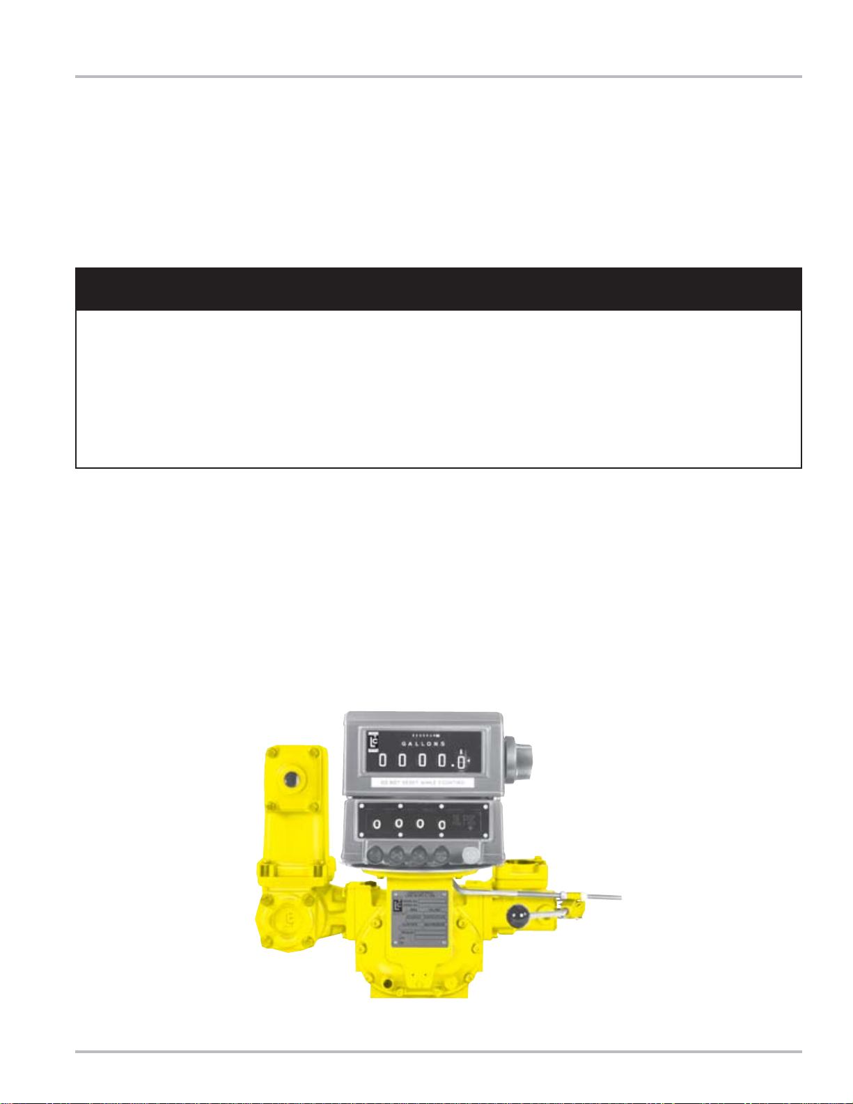
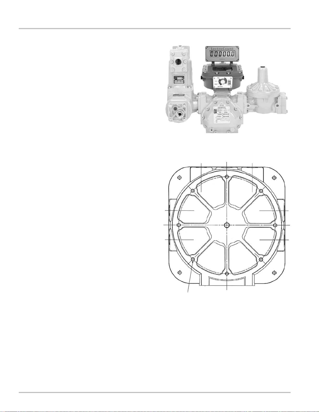
Removing Existing Mechanical Registration Equipment
Liquid Controls Meters
Remove the mechanical register components by
removing the four bolts that attach the register “stack” to
the meter. (See illustration below).
Neptune Fuel Oil Meters
Remove the mechanical register from the meter, leaving
just the star shaped gear and two square headed studs.
Neptune LPG Meters with Mechanical TVC’s
Remove the mechanical register and the mechanical
automatic temperature compensator from the meter
leaving just the star shaped gear.
Removing mechanical register stack from Liquid Controls meter (typical).
7
Page 8
LCR Register Mounting
The LCR register is usually mounted on the liquid flow
meter, though for fixed installations it can be mounted
up to 1000 wire feet (304.0 meters) away from the meter
if the meter is equipped with an external pulser. The
actual distance depends on the pulser specifications and
the type of wire used to install it. Contact the factory if
your installation requires pulser or RTD cable lengths
greater than 1000 feet.
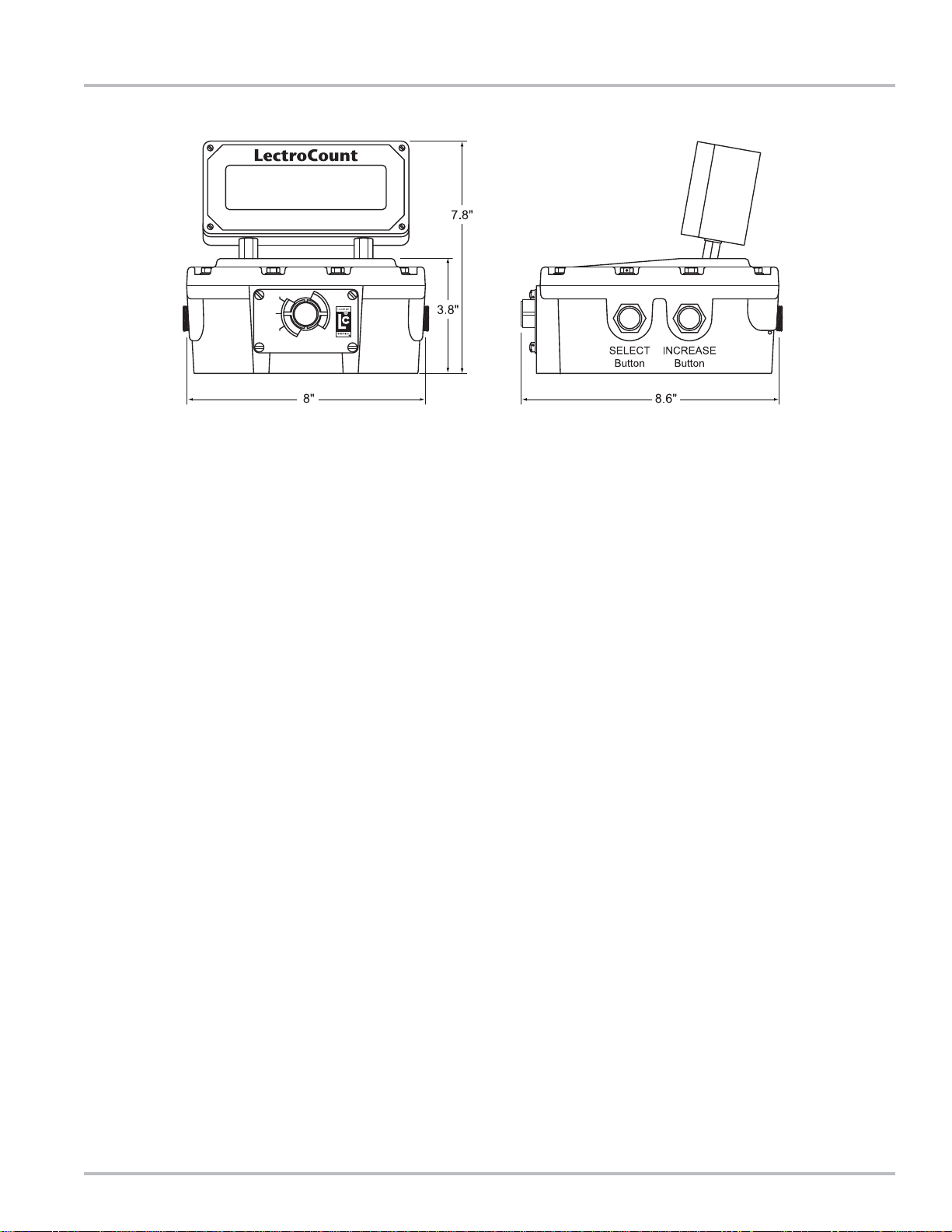
LCR Mounting Bolt Pattern
The LCR base casting contains eight mounting holes in
an industry standard bolt pattern that allows it to be easily
attached to a number of common meters. All of the holes
are 1/2” deep and will require 1/4 - 20” screws.
Refer to the drawing below if you will need to fabricate a
mounting bracket for the LCR. Brackets and adapters
are available from Liquid Controls for many common
meters. Installation instructions are packed with the
mounting or adapter kit. When mounting the LCR, leave
the cover assembly fastened to the base to protect the
internal components. As the LCR is placed on top of the
meter, make sure the vertical drive shaft from the meter
is attached to the pulser drive shaft using the kit provided.
Before securely fastening the LCR to the meter or
bracket, make sure that the counter is visible and that
the selector switch can be easily operated.
NOTE: If the LCR will be exposed to the elements before
the installation is complete, make sure that the cover
gasket is in place and that all (12) M8 mounting bolts
and washers are snugly installed. Also, remove all of
the pipe plugs from the LCR’s seven 1/2” NPT conduit
hubs, apply pipe sealant or Teflon tape to the threads,
then re-install the plugs in the ports.
NOTE: When removing/installing cover screws, switch
plate screws, or display cover screws, apply antiseize
compound to the screws upon reassembly to ensure easy
removal at later date.
Mounting Holes:
.250-20 UNC -2B .50 Deep
8 Holes Equally Spaced on a 6.65 Dia. Circle.
8
Page 9

Valve Installation
General
The LCR can provide security valve and preset control
capabilities via the Solenoid 1 and 2 outputs. Singlestage and two-stage solenoid actuated valves and threeway solenoids can be controlled. Valves should be
installed in accordance with accepted industry practice
and Weights & Measures regulations. NOTE: The
modulated two-solenoid valves designed for use with the
LectroCount3 cannot be used with the LCR.
LPG and NH3 Truck Installations
The differential valve used on many LPG trucks can be
used in conjunction with Liquid Controls 3-way solenoid
kit as a security valve. Since the differential valve is
installed after the meter, little of the piping has to be
modified.
The 3-way solenoid mounts to the LCR via the rear middle
port using the short 1/2” NPT nipple and explosion proof
union supplied with the kit. Port A is connected to the
vapor eliminator’s vapor port. Port B is connected to the
differential valve’s diaphragm. Port C is connected to
upstream system pressure. See illustration below.
If the solenoid is not energized by the LCR, upstream
high pressure liquid is directed to the valve diaphragm
and the valve closes, preventing product from being
delivered.
When the solenoid is energized by the LCR’s SOL-2
signal, the vapor eliminator’s control port is connected
to the differential valve. This allows the valve to function
normally: if the vapor eliminator is filled with liquid, the
pressure on the valve (bonnet) is low and the valve opens,
allowing product to be delivered. If the fluid level in the
vapor eliminator drops, high pressure gas will be directed
to the valve bonnet, and the valve will close.
NOTE: Liquid Controls’ supplied 3-way solenoids can
have either of two labeling schemes. Check to determine
which 3-way solenoid has been supplied with your kit.
Install as indicated below.
Port Connections:
A (or R) - connected to air eliminator vapor port.
B (or B) - connected to valve diaphragm.
C (or P)- connected to upstream system pressure.
9
Page 10
Valve Installation
Fuel Oil Trucks Preset/Security Valve Installation
Installing an LCR on a refined fuel truck typically requires
the removal of the system’s mechanical valve. Those
trucks equipped with air check valves should retain them
as part of the air elimination system. However, an air
check valve will not perform well as a preset/security valve
on fuel trucks.
Liquid Controls can provide two-stage or single-stage
valves that provide the security and accurate presetting
functions. The valve control software in LCR compares
the volume delivered to the preset amount and
automatically adjusts itself to deliver the correct preset
quantity.
Two-Stage Valves
Two-stage valve solenoids should be connected to the
LCR’s valve control outputs (SOL-1 and SOL-2). When
both of the solenoids are energized, the valve will be
operating at full flow. When SOL-1 is turned off, the valve
will operate at a reduced or dwell flow rate. If neither of
the solenoids is energized, the valve will close, stopping
product flow.
NOTE: A 2-inch Preset Valve can be used with a 3-inch
meter system if the flow rate does not exceed 160 GPM.
Single-Stage Valves
Single-stage solenoids should be connected to the SOL2 control. When the solenoid is energized, the valve will
open to the maximum flow rate.
On certain applications, trucks equipped with LC V-7
mechanical valves can be retrofitted with LC air valve
actuators to provide single-stage shut-down and solenoid
block functions. These systems require truck system
compressed air to function. Consult Liquid Controls for
more information.
Special Note for Canadian Installations
Canadian Weights & Measures regulations require that
the preset valve on truck systems be located after the
meter. In addition they require that a manual ball type
valve be located between the meter and the hose reel.
Liquid Controls recommends that the manual ball valve
be located after the preset valve and before the hose
reel.
Install the preset valve in the pipe between the meter
and the hose reel or manual shut-off valve. If an air check
valve is present in the system, leave it in place.
Make sure that the preset valve is installed in the correct
orientation with respect to fluid flow. On many valves
the flow direction is indicated by an arrow on the valve
body.
10
Page 11

Wiring the LCR
!!
!!
!
WARNINGWARNING
WARNINGWARNING
WARNING
Power, input and output (I/O) wiring must be in
accordance with the area classification for which it is
used (Class I, Div 2). For North America, installations
must be per the U. S. National Electrical Code, NFPA
70, or the Canadian Electrical Code in order to maintain
Class I, Division 2 ratings. This may require using
connections or other adaptations in accordance with
the requirements of the authority having jurisdiction.
General
Once the LCR, and optional equipment such as control valve and ETVC kit have been installed in accordance with
instructions supplied with the units, wiring connections need to be made from those components to the LCR. The user
supplied wiring for all connected equipment must be routed through suitable conduit to the LCR. Threaded pipe
conduit, Liquid Tight, and Synflex are among some choices. If plastic Synflex fittings are used, make sure that they are
rated for outdoor use, temperature and gas/oil service. The conduit hubs on the LCR are all 1/2” - 14 NPT. Recommended
conduit routings are shown to the right. For your convenience in wiring, all terminal blocks on the LCR are removable
by pulling straight up. CAUTION: The conduit/cable entrances must be sealed inside and out using appropriate cable
glands to prevent moisture from entering in the LCR.
WARNING: Explosion Hazard - Substitution of
components may impair suitability for Class I, Division
2 applications.
WARNING: Explosion Hazard - When in hazardous
locations, turn power OFF before replacing or wiring
modules.
WARNING: Explosion Hazard - Do NOT disconnect
equipment unless power has been switched OFF or
the area is known to be Non-Hazardous.
11
Page 12

Wiring the LCR
Wiring of Valve Solenoids to LCR
When wiring valve solenoids to the LCR, the wires may
have to be spliced in order to reach the appropriate
terminal strip location. Use stranded 18 GA wire. It is
recommended that red wire be used for the main
connections, though black can be used as a substitute.
Green 18 GA stranded wire should be used for the
solenoid case ground. Leave a small amount of excess
wire to allow for future servicing of the junction box wiring.
Single-Stage Valve and Three-Way Solenoid Wiring
Single-stage (security) valve solenoid (S2) or three-way
solenoid (LPG service) should be wired into terminal block
J13, Pins 17, 18, and 19, as shown on page 14. Solenoid
operates when the LCR pulls SOL-2 (Pin 18) signal low.
Two-Stage Valve Solenoid Wiring
The S1 and S2 solenoids are connected to terminal block
J13, Pins 14, 15, 16, and 17, 18, and 19, respectively, as
shown on page 14. The SOL-1 signal is connected to
the bonnet solenoid (S1). The SOL-2 signal is connected
to the bypass solenoid (S2). Each solenoid will be turned
on when the LCR pulls its respective signal low (SOL-1;
SOL-2).
Wiring RTD Temperature Probe to LCR (Optional)
Make sure that there is enough slack in the conduit
leading from the LCR to the strainer mounted RTD to
allow the strainer cover to be removed. Feed the cable
from the back of the RTD through the conduit to the LCR.
Cut the cable on the LCR end, leaving enough to expose
a few inches of the wires inside. Strip the insulation from
the wires and connect them to terminal block J14, Pins
20, 21, 22, and 23, as shown on page 14. The two white
wires are connected to Pins 20 and 21, and the two red
wires to Pins 22 and 23.
Connecting Lap Pad to LCR (optional)
The optional Liquid Controls Lap Pad is connected to
the printer in the cab of the truck. Each Lap Pad is
provided with a 3-terminal Lap Pad Adapter that provides
a junction for the Lap Pad, the printer, and the LCR printer
cable. The Lap Pad adapter is inserted in the port at the
back of the printer. Then, the printer cable from the LCR
is installed in the back of the adapter. Refer to page 14.
NOTE: The jumper on terminal J10 on LCR circuit board
must be in the RS-232 position for operation of the Lap
Pad (factory set position). See page 14.
12
Page 13

Installing factory-supplied printer Power cable, LCR
Power Cable, and printer data cable
Your LCR includes an electrical black-sheathed10conductor printer data cable for connecting the LCR at
the rear of the vehicle to the printer located in the vehicle
cab, and a separate gray-sheathed 3-wire power cable
for connecting the LCR to the accessory circuit in the
vehicle cab. For your convenience, the cables have been
factory pre-wired to the LCR, and are ready for routing
to the vehicle cab. The cable assemblies should be run
in 3/4” automotive black plastic corrugated split loom to
protect the cables from the elements. Make sure the
loom is securely fastened to the truck. NOTE: Be
especially careful to keep the cables away from hot
surfaces, rotating shafts, and moving linkages.
Printer Data Cable (P/N 81513040)
Connect the D-connector on the free end of the black
printer data cable to the receptacle on the back of the
printer in the vehicle cab. NOTE: The socket labeled
“KD”(telephone style connector) on the back of the printer
is NOT used. Printer may be located a maximum of 50
feet from LCR.
Printer Power Cable (24 VDC)
Printer power is supplied through the socket labeled “24
VDC” on the back of the printer. The 82500 DC/DC
converter plugs into this socket. The pigtail end of the
82500 must be connected to the accessory circuit (red)
to 12 VDC and (black) to system ground. See page 14.
Wiring the LCR
Wiring the pod pulser to lcr (optional)
LCR is most commonly supplied with an internal pulser
for the convenience of the customer. In such cases, the
optional external POD pulser is not used. If the LCR is
located remotely from the meter, the POD pulser is
required to supply pulse outputs to the LCR.
The POD pulser should be installed in accordance with
the installation instructions supplied with the POD (Series
E200 Installation, and Operation Manual). Wire the POD
to terminal block J8, Pins 31, 33, 34, and 37, as shown
on page 15. Route wires from the POD into the LCR
through Port 6.
NOTE: For connection of other design pulsers, refer to
page 19 of this manual.
LCR Power Cable (P/N 81512)
Connect the black lead of the power cable for the LCR to
a suitable grounding point in the cab. Connect the red
lead to a source of 12 VDC power that is on the vehicle
“accessory” circuit (the LCR is designed to be “OFF”
when the vehicle is turned off). Typically the ignition
switch and the fuse panel are sources of 12-volt power.
If power is drawn from a fuse tap, make sure the cable
connection is on the load side of the fuse. The power to
the LCR should be “OFF” when the truck ignition switch
is in the “OFF” position. NOTE: The LCR Power Cable
Kit includes a 5 Amp fuse holder and fuse to protect the
truck system in the event of a short circuit in the cable.
Liquid Controls recommends that this fuse be used in all
installations not having a fused accessory panel already
in the truck. See page 14. A 5 Amp fuse is required.
CAUTION: Electrical Power must be off until all wiring
operations have been completed.
Wiring odometer PULSER to lcr (optional)
The Odometer pulser is mechanically installed on the
vehicle in accordance with the installation manual
provided with the odometer kit. The 3-wire cable from
the odometer pulser is wired to terminal block J8, Pins
31, 36, and 38, as shown on page 15. Route wires from
the odometer pulser into the LCR through Port 6.
13
Page 14

Wiring the LCR
Wiring Customer-Furnished Remote START/Stop
Switch to LCR (Optional)
A user-supplied momentary remote START/STOP Switch
can be connected to terminal block J8, Pins 36 and 38 in
lieu of the odometer pulser. For programming instructions
to activate the user supplied remote START/STOP
Switch, refer to the LCR Set-up Manual (Bulletin No.
500050).
Preset/product Selector switch (optional)
LCR can be provided with a factory installed optional
preset switch for setting a preset delivery quantity from
the back of the vehicle. The preset switch is connected
to terminal block J8, Pins 35 and 38, as shown on page
15. For instructions on the operation of the preset switch,
refer to the LCR Set-up Manual (Bulletin No. 500050).
NOTE: The preset switch can also be used to select
one of four different products. Refer to the LCR Set-up
Manual for details.
Communication protocol selector switch (optional)
LCR can be provided with a factory installed optional
communication protocol selector switch. This optional
switch, which is housed in Port No. 1 on the LCR, allows
the user to select the RS-232 communication protocol
for use with the Liquid Controls Lap Pad terminal (switch
in “up” position), or the RS-485 protocol for use with a
handheld computer (switch in “down” position). This
protocol selection can be made without breaking Weights
& Measures seals on the LCR. Without this switch, any
change in protocol selection requires breaking Weights
& Measures seals to gain access to jumper switches on
the LCR circuit board (terminal J10).
CAUTION: This switch must only be activated with power
to the LCR “OFF”. If the protocol selector switch position
is changed with power supplied to the unit, the
microprocessor memory contents may be destroyed and
data will be lost. If this switch is installed or replaced in
the field, the wiringharness MUST be attached to the
circuit board as shown on page 15, with the notched side
of the connector facing in.
connecting handheld or lap top computer
The LCR is capable of interfacing to a handheld or lap
top computer. In such cases, the optional RS-232 to
RS-485 Converter is connected to terminal block J2, Pins
24 and 25, as shown on page 15. The computer, in turn,
is connected to the D-connector in the Converter.
NOTE: When a handheld or lap top computer is used to
interface to the LCR, the LCR must be configured for the
RS-485 communication protocol. This can be
accomplished either by means of the selector switch
(described above), or by means of selecting the
appropriate jumper setting at terminal J10 on the LCR
circuit board. Refer to the figure on page 14 for details.
connecting auxiliary outputs (optional)
Aux 1, terminal block J12, Pin 44: This signal can be
turned OFF, ON, or ON when the LCR enters the RUN
state. It remains OFF, ON, or ON until the LCR ends the
delivery. See LCR Set-up Manual for programming
options.
Aux 2, terminal block J12, Pin 43: This signal can be
turned on when the LCR enters the reverse flow state. It
remains off during forward flow. Optionally, it can can
function like Auxiliary Output 1. See LCR Set-up Manual
for programming options.
Pulse, terminal block J12, Pin 42: This output
represents the gross delivery quantity if the LCR is making
an uncompensated delivery. The output represents net
delivery quantity if the LCR is equipped with the
temperature compensation option and the system has
been configured for net delivery. This is a real time 50/
50 duty cycle output representing the least significant
digit of LCR totalizers.
DN/UP Counts, Terminal Block J12, Pins 39 and 40:
These signals are duplicates of the signals sent to the
LCR counter via connector J7. They can be used to
integrate an additional counter into the system. These
outputs are used to control the 6-digit LCD local display.
The up and down counters are pulsed so that the counter
displays the gross delivery quantity, or net delivery
quantity if compensated. Pulses are active low and are
approximately 5 μsec in duration. The LCD counter is
reset by turning on both outputs for 0.01 second. Refer
to table on page 18 for wiring connection instructions for
Auxiliary outputs, pulse outputs, and DN/UP count
outputs.
14
Page 15

Wiring the LCR
Installing a Valve with 110VAC Solenoids
This step applies only to configurations that will be using
a two-stage valve with 110VAC solenoids.
Using a two-stage valve with solenoids operating on
110VAC requires the use of two relays. These relays
must operate at +12VDC and the contact rating must be
greater than the current draw for the device being
switched. The relays must be SPST (single pole, single
throw) and be normally open.
For installation of the valve the following parts will be
need:
• Cable, 2 conductor, stranded 20 GA
• Flexible liquid-tight conduit, ½" diameter and ½" NPT
conduit connectors or cable glands
• Teflon tape or pipe sealant
• 2 SPST, normally open relays
Installation Procedure
1. Install the valve between the meter and the hose reel.
If there is a manual ball valve installed in the system,
make sure it is after the two-stage valve and before
the hose reel. If an air check valve is present in the
system, leave it in place.
6. Run the cables through the conduit or cable gland
between the solenoids and relays and then connect
the conduit to the solenoid valve and the relays.
7. Wire the solenoids to the relays as shown in the figure
to the right.
8. Run the cables through the conduit or cable gland
between the relays and register and then connect
the conduit to the relays and the register.
9. Wire the relays to the register as shown in Figure 9.
10. Wire the 110VAC source to the solenoids according
the solenoid manufacturer’s instructions.
2. Install the relays in an appropriate location based on
the requirements of the environment. Follow all
applicable codes.
3. Install cable glands or conduit connectors on each
solenoid valve and on the LCR ports. Use Teflon
based pipe sealant or Teflon tape on the threads.
4. Cut the conduit to the length required between the
port on the register and the relays, and between the
relays and the corresponding valve solenoids.
5. Cut the cable 6" longer than the lengths of conduit or
the cable run.
6. Using wire strippers, strip-off the insulation (approx.
1¼") on each end of the cable and off the tip of the
conductors (approx. ¼").
15
Page 16

Guidelines for Environmental Sealing
The LCR contains a printed circuit board with sensitive
electronic components that can be damaged by the
presence of moisture. Conformal coating on the board
and a moisture-absorbing desiccant inside the enclosure
mitigates the problem of moisture corroding the LCR
board. These measures protect the board from small
amounts of moisture trapped inside when the lid is closed
in humid conditions, but are not adequate in protecting
the unit over time if a continuing leak in the enclosure is
present. Therefore, it is necessary to adequately seal
all openings to the unit during installation. The LCR is
rated NEMA 4x making it capable of pressure washing
when seals are adequately applied, as described below.
1. Conduit Entrances
The LCR has seven conduit entrances each with 1/2 14 NPT female threads. Use only 1/2 - 14 NPT male
threaded fittings on all conduit entrances. Pressed in
Caplugs are inadequate as seals for these entrances.
Straight rather than tapered threads are also inadequate.
Acceptable fittings are either metal or plastic conduit, pipe
plugs, or cable glands. Threads should be treated with
a Teflon based “pipe dope” or taped using a minimum of
two revolutions of Teflon tape prior to installation. Threads
should be engaged a minimum of four full turns. When
using cable glands be sure that the gland is sized properly
for the outside diameter of the cable being sealed and
that the elastometric seal around the cable sheath is
compressed onto the cable. Use only one cable per cable
gland unless the gland is designed for multiple cables.
When using conduit or Liquid-Tite make sure that the
opposite end is going into an environmentally sealed
device as well. For example, some solenoid valves are
rated for hazardous locations but may not be sealed
environmentally. If the conduit is not sealed on the other
device, fill the interior of the conduit at the LCR with a
silicone rubber sealant such as RTV to prevent moisture
from running down the conduit into the LCR
enclosure.Refer to “Wiring The LCR” notes on page 10
for code requirements.
2. Cover Seals
The covers on both the LCR and its Remote Electronic
Counter (REC) are provided with 0-ring seals to prevent
moisture ingress. The LCR O-ring must be inserted in
the groove of the cast housing
prior to the cover being attached. All twelve bolts must
be tightened to compress the cover O-ring adequately.
The O-ring on the REC is integral to the REC cover. All
four cover screws must be tightened to effect a seal on
the REC cover.
3. Shaft Seals
Units with internal pulsers have an O-ring seal around
the pulse encoder drive shaft emanating from the bottom
of the LCR. Various drivers can be attached to this shaft
to adapt to industry standard PD flow meters. When
installing a driver make sure not to remove the O-ring
that is around the drive shaft embedded in the base
casting. The O-ring should be seated in the counter bore
in the casting and covered with the flat washer provided
before attaching a driver using the cotter pin. The control
switch on the front of the LCR is also sealed with an Oring that is held in place by a bushing secured with three
socket head cap screws. In the event that a control switch
is replaced in the field, make sure that the O-ring is in
place on the switch shaft before reinstalling the switch
bushing.
16
Page 17

After the LCR has been installed, check to make sure
that it will power up correctly. The back light on the LCR
display should go on when the truck’s ignition key is
turned to the “ON” or the “accessory” position. At this
point, you need to attach a compatible data terminal to
the LCR to initialize system values, set the clock, enter
ticket headers, calibrate the meter, etc. The user can
use a Liquid Controls Lap Pad, handheld computer, or
lap top computer.
Lap Pads and computers emulating a VT-100 terminal
must be connected to the RS-232 terminal port (J3
Terminal Block). The LCR must be configured for RS232 operation by proper positioning of the jumper on the
J10 terminal block, as shown on page 14.
Refer to the Liquid Controls LectroCount LCR Setup
Manual (Bulletin #500050) if you will be using a Lap Pad
or VT-100 compatible terminal to set up the LCR.
System Startup
17
Page 18

Wiring Schematic
18
Page 19

Wiring Schematic
19
Page 20

Wire ConnectionTables
This appendix provides a tabular description of the wiring connections made to each LCR-II terminal block. It should
be referenced in the event wiring inadvertently mis-routed in the field, or for general troubleshooting in the event of a
problem.
PRINTER CONNECTION (J1)
Connector/
Pin
J1-30 GN D Printer, Pin 7
29 CT S Printer, Pin 20
28 RXD Printer, Pin 2
27 TXD Printer, Pin 3
26 RT S Printer, Pin 6
Signal Route To:
Wire Color
Cab le #81513
Black
Blue
Yello w
Orange
Brown
TERMINAL CONNECTION RS-485 (J2)
Connector/
Pin
J2-25 485-B Black Viloet Terminal
24 485+A Red Red Terminal
Signal
Wire Color
Cable
#81572
Cable
#81513
Route To:
POWER CONNECTION (J6)
Connector/
Pin
J6-13 Earth Drain/Green Wire No Connection*
12 GND Black DC Ground
11
*On free-end of cable, cut off foil shield and drain wire,
then insulate by taping.
NOTE: The LCR-II Power cable kit includes a fuse holder
and 5 Amp fuse to protect the system in the event of a
short circuit in the cable. Liquid Controls recommends
that this fuse be used in all installations not having a
fused accessory block to protect the truck in the event of
cable faults. A 5 Amp fuse is required.
Signal Wire Color Route To:
+12V In
(or +24V In)
Red
+12VDC (or +24VDC)
(accessory truck circuit)
NOTE: Jumper J10 on LCR circuit board must be set for
RS-485 communication protocol.
LAP PAD CONNECTION RS-232 (J3)
Connector/
Pin
J3-51 GND Ground, Pin 5
50 CTS RTS Terminal, Pin 4
49 RXD TXD Terminal, Pin 3
48 TXD RXD Terminal, Pin 2
47 RTS CTS Terminal, Pin 8
46 +Vo Lap Pad +12, Pin 8
Signal
NOTE: Jumper J10 on LCR-II circuit board must be set
for RS-232 communication protocol.
* For a standard RS-232 terminal (other than the Lap
Pad), the black wire is connected to J3-47.
Wire Color
Cable #81513
White
Green
Gray
Violet
*
Red
Route To:
ODOMETER, PRESET/PRODUCT
SELECTOR SWITCH, START/STOP
SWITCH, AND INTERNAL PULSER
CONNECTIONS (J8)
Connector/
Pin
J8-38 GND Black
37 GND Black
36 In1 Violet
35 In2 Gray Preset switch
34 In3 Green Int. Pulser "B"
33 In4 White Int. Pulser "A"
32 +5V Out Red Int. Pulser "+"
31 +Vo Odometer +12V
Signal Wire Color Route To:
Preset switch or Remote
Start/Stop sw itch
Internal pulser and
Odometer ground
Odometer pulser or
remote Start/Stop switch
20
Page 21

Wire Connection Tables
LIQUID CONTROLS POD (J8)
Connector/
Pin
J8-38 - - -
37 GND Black Pulser Signal GND
36 - - 35 - - 34 In 3 Green Channel B Output
33 In 4 White Channel A Output
32 - - 31 +Vo Red +V Input
Signal Wire Color Route To:
SINGLE CHANNEL PULSER (J8)
Connector/
Pin
J8-38 - - -
37 GND N/A Pulser Signal GND
36 - - 35 - - 34 33 In 4 N/A Pulse Output
32 - - 31 +Vo Red +V Input
Signal Wire Color Route To:
AUXILIARY OUTPUTS (J12)
Connector/
Pin
J12-45 +Vo N/A
44
43
42 Out 3 N/A
41 GND N/A
40 Out 4 N/A Display Input
39 Out 5 N/A Display Input
Signal Wire Color Route To:
Out 1
(Aux. 1)
Out 2
(Aux. 2)
N/A
N/A Flow Direction
Pump or
Aux. Control
Pulse Input for
Aux. System
VALVE SOLENOID CONNECTION (J13)
Connector/
Pin
J13-19 Earth Green
18 Out 6 Black or Red Solenoid 2
17 +Vo Black or Red Solenoid 2
16 Earth Green
15 Out 7 Black or Red Solenoid 1
14 +Vo Black or Red Solenoid 1
Signal Wire Color Route To:
Solenoid 2
Case Ground
Solenoid 1
Case Ground
NOTE: To operate a single channel pulser, a jumper is
required between pins 2 and 3 on J4.
VEEDER ROOT SOLID STATE QUAD
PULSER (J8)
Connector/
Pin
J8-38 - - -
37 GND White Pulser Signal GND
36 - - 35 - - 34 In 3 Orange Channel B Output
33 In 4 Black Channel A Output
32 - - 31 +Vo Red +V Input
NOTE: Pull-down resistors of 300 Ω needs to be
connected between CHAN B and GND, and CHAN A and
GND.
Signal Wire Color Route To:
RTD TEMP. PROBE CONNECTION (J14)
Connector/
Pin
J14-23 RTD-D White RTD
22 RTD-S White RTD
21 RTD+D Red RTD
20 RTD+S Red RTD
Signal Wire Color Route To:
21
Page 22

Illustrated Parts Breakdown
22
Page 23

Illustrated Parts Breakdown
23
Page 24

A Unit of IDEX Corporation
105 Albrecht Drive
Lake Bluff, IL 60044-2242
1.800.458.5262 • 847.295.1050
Fax: 847.295.1057
www.lcmeter.com
© 2007 Liquid Controls
Pub. No. 500049
(05/07)
 Loading...