

Page 1

Installation & Parts Manual
K-7, K-15, & K-30
Air Actuated & Differential Check Valves
Installation: M400-30
www.lcmeter.com
Page 2

Table of Contents
!!
!!
! WARNING
• Before using this product, read and understand the instructions.
• Save these instructions for future reference.
• All work must be performed by qualified personnel trained in the proper application, installation, and maintenance
of equipment and/or systems in accordance with all applicable codes and ordinances.
• Failure to follow the instructions set forth in this publication could result in property damage, personal injury, or
death from fire and/or explosion, or other hazards that may be associated with this type of equipment.
Description Page Number
General Information ..................................................2
Specifications ............................................................3
K-7 Valves .................................................................4-5
Installation .................................................................4
New Installations .......................................................4
Retrofit Installations...................................................4
Disassembly and Reassembly ..................................5
K-15 Valves ...............................................................6-7
Installation .................................................................6
New Installations .......................................................6
Retrofit Installations...................................................6
Description Page Number
Disassembly and Reassembly ..................................7
K-30 Valves ...............................................................8
Installation .................................................................8
New Installations .......................................................8
Retrofit Installations...................................................8
Illustrated Parts Breakdown ......................................9-11
K-7 Valves .................................................................9
K-15 Valves ...............................................................10
K-30 Valves ...............................................................11
Publication Updates and Translations
The most current English versions of all Liquid Controls publications are available on our website, www.lcmeter.com.
It is the responsibility of the Local Distributor to provide the most current version of LC Manuals, Instructions, and
Specification Sheet s in the required language of the country, or the language of the end user to which the products are
shipping . If there are questions about the language of any LC Manuals, Instructions, or Specification Sheets, please
contact your Local Distributor.
General Information
Liquid Controls Air Actuated/Differential Check V alves
are designed to prevent flow whenever air or vapor is
present, thereby assuring accurate measurement.
Check Valves are normally closed, spring loaded valves
installed on the meter outlet. When fluid enters the valve
from the inlet side, and the pressure is greater than the
back pressure combined with the force of the spring, the
spring will compress, opening the valve and allowing fluid
K-7 Valve Operation
to pass through (as shown in the figure below).
When back pressure plus spring strength is greater than
the fluid pressure entering the meter, the valve will remain
closed.
These meters are used in conjunction with the air/vapor
eliminator to prevent air/vapor from being metered. This
is important when split compartment testing.
2
Page 3

Model/Applications
K-7 Valves:
Model No. Material Spring Seals Applications
A2811 Cast Iron Standard Viton Chlorinated Solvents
A2817 Aluminum Standard Viton Petroleum Products
A28171 Aluminum Medium Viton Petroleum Products
A28172 Aluminum Heavy Duty Viton Petroleum Products
A2821 Aluminum Standard PTFE Liquid Sweeteners, Methanol
A2826 Aluminum Standard Viton Liquid Sweeteners
A2831 Cast Iron Standard PTFE Caustics
A2851 Aluminum Standard EPT NH3 Applications.
A2862 Stainless Steel Standard PTFE Acidic PH Liquids
K-15 Valves:
Model No. Material Spring Seals Applications
A3830
Aluminum,
Aluminum Guide
Standard Viton Aviation Fuels
A3845
Aluminum,
Bronze Guide
Standard Viton Petroleum Products
K-30 Valve:
Model No. Material Spring Seals Applications
A4845 Aluminum Standard Viton Petroleum Products
Used on M-5 & M-7 - 1½" & 2" Meters
Maximum Flow Rate = 150 gpm (568 lpm)
Working Pressure: 150 psi (10.5 bar)
Used on M-15 & M-25 - 3" Meters
Maximum Flow Rate = 300 gpm (1,136 lpm)
Working Pressure = 150 psi (10.5 bar)
Used on M-30 - 3" Meters
Maximum Flow Rate = 300 gpm (1,136 lpm)
Working Pressure = 150 psi (10.5 bar)
Specifications
K-7 Valves
3
K-15 & K-30 Valves
Page 4

K-7 Valves
!!
!!
!WARNING!
Before disassembly of any meter or accessory component, ALL INTERNAL PRESSURES MUST
BE RELIEVED. Pressure must be 0 (zero) psi. Close all liquid and vapor lines between the
meter and liquid or gas pressure source (such as the supply tank, discharge lines and supply
lines).
New Installations
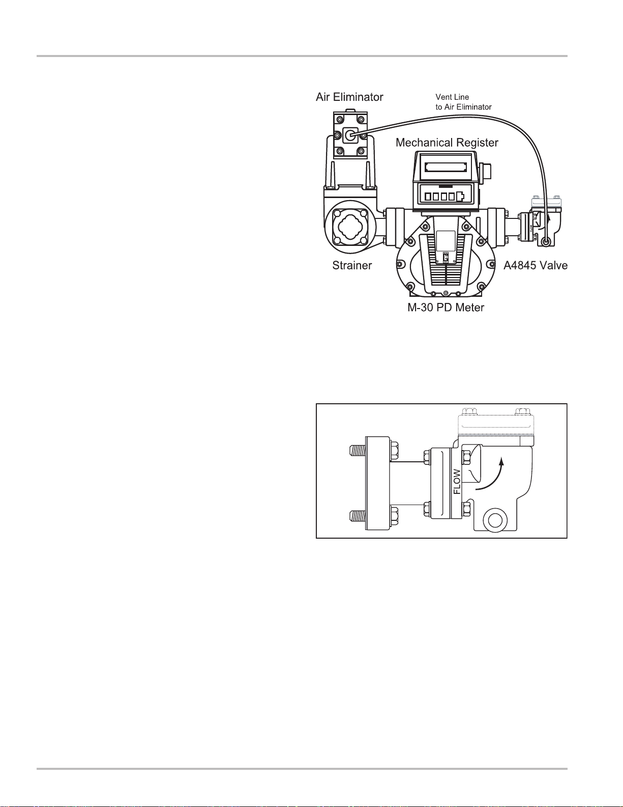
When ordered with a new metering system, the Check
Valve is supplied mounted to the metering system as
shown to the right. A line must be connected to the flange
on the outlet side of the 2-stage, preset valve. This flange
connection is 2” NPT.
Finally, install a vent line from one port of the check valve
to the air eliminator. Plug the other side of the check
valve.
Retrofit Installations
Depending on the existing configuration, adding a Check
V alve may require modification of the outlet piping.
After the internal pressure is relieved from the system,
the output line can be disconnected from the output side
of the meter. If the system includes an electronic, 2stage, preset valve, remove it from the meter. The check
valve assembly can then be connected to the output side
of the meter.
Use the four bolts and washers to fasten the valve
assembly to the meter. The valve has an arrow showing
the direction of flow. Ensure that the valve is properly
oriented.
Tighten the bolts in a crossing pattern. Once the check
valve is secure, the electronic, 2-stage, preset valve can
be connected to the back check valve as shown to the
right. Once this is complete, the output piping may be
reconnected to the electronic, 2-stage, preset valve. The
preset valve output fitting is 2” NPT.
Run a line from one port of the check valve to the air
eliminator. Plug the other side of the check valve.
4
Page 5

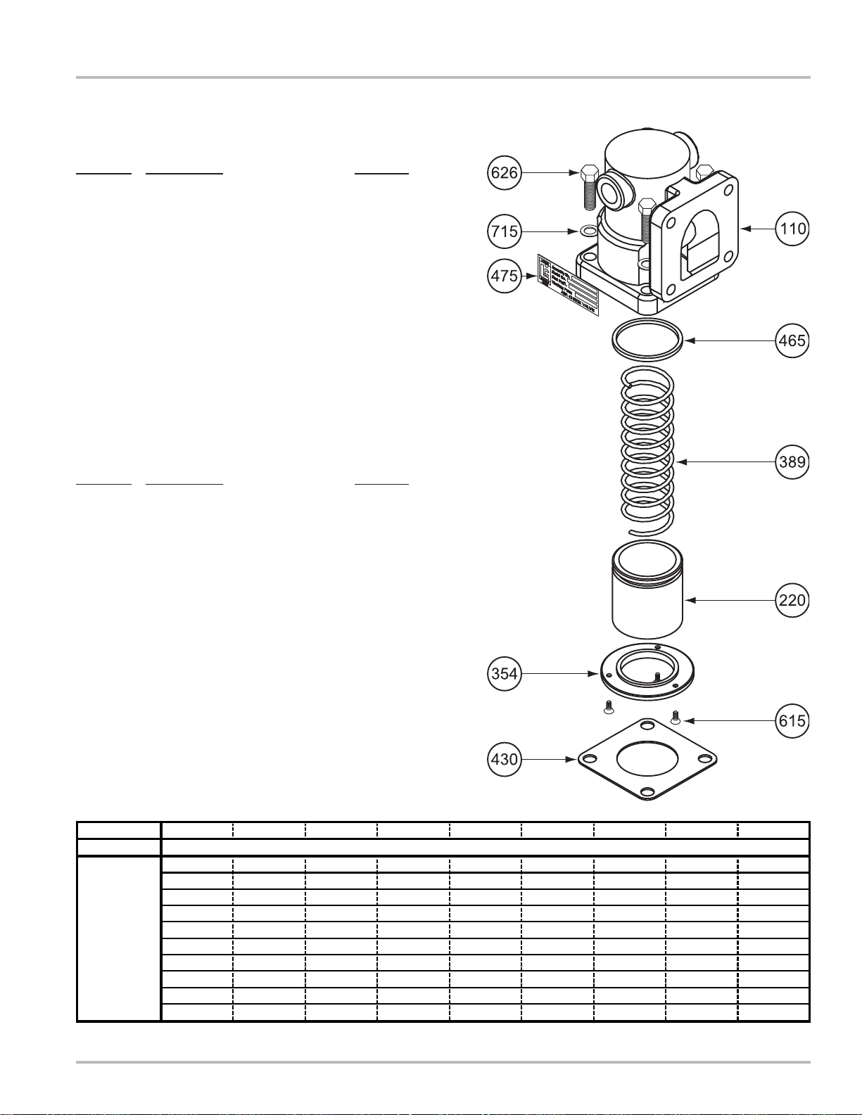
Disassembling the K-7 Valve
NOTE: Refer to the illustrated parts breakdown to the right
for Item Numbers referenced in these instructions. Item
Numbers appear in circles in the drawing.
1 Use a fixture to press and hold the piston (Item 220)
in place with the compression spring (Item 389)
compressed.
2 Loosen the three screws (Item 615) that hold the seal
ring (Item 354).
3 Slowly remove the fixture holding the piston (Item 220)
and compression spring (Item 389) until the spring
exerts NO pressure.
4 Remove the seal ring (Item 354), piston (Item 220)
and compression spring (Item 389).
5 Remove the Quad Ring (Item 465) from the piston
(Item 220). Replace necessary components and
reassemble.
K-7 Valves
Reassembling the K-7 Valve
1 Place the compression spring (Item 389) over the
valve stem in the valve housing (Item 110).
2 Place the Quad Ring (Item 465) on the piston (Item
220).
3 Place the piston (Item 220) over the compression
spring (Item 389).
4 Place the seal ring (Item 354) on the piston (Item 220).
5 Place the piston (Item 220) and seal ring (Item 354)
on top of the compression spring (Item 389) and
compress using a fixture to hold the assembly in
place, leaving the seal ring (Item 354) free to rotate.
6 Line up the holes of the seal ring assembly (Item 354)
with the holes of the housing assembly (Item 110)
and screw in the three screws (Item 615). Tighten
the screws.
7 When the screws are tight, remove the fixture used
to hold the piston and spring in compression.
5
Page 6

K-15 Valves
!!
!!
!WARNING!
Before disassembly of any meter or accessory component, ALL INTERNAL PRESSURES MUST
BE RELIEVED. Pressure must be 0 (zero) psi. Close all liquid and vapor lines between the
meter and liquid or gas pressure source (such as the supply tank, discharge lines and supply
lines).
New Installations
When ordered with a new metering system, the Check
Valve is supplied mounted to the metering system as
shown in the example to the right. A line must be
connected to the flange on the outlet side of the check
valve. This flange connection is 3” NPT.
Mechanical Register
Air Eliminator
Finally, install a vent line from one port of the check valve
to the air eliminator. Plug the other side of the check
valve.
Retrofit Installations
Depending on the existing configuration, adding a Check
V alve may require modification of the outlet piping.
After the internal pressure is relieved from the system,
the output line can be disconnected from the output side
of the meter. In the example to the right, the output line
would be connected to the V-15 valve. The check valve
assembly can then be connected to the output side of the
V-15 valve.
Use the four bolts and washers to fasten the check valve
assembly to the V-15 valve. The check valve has an arrow
showing the direction of flow. Ensure that the valve is
properly oriented.
Tighten the bolts in a crossing pattern. Once the check
valve is secure, the output line may be reconnected to
the output side of the check valve. The output fitting is 3”
NPT .
V-15
Valve
Strainer
K-15 Check Valve
M-25 PD Meter
A vent line must be connected from one side of the check
valve to the air eliminator. Plug the other side of the check
valve.
6
Page 7

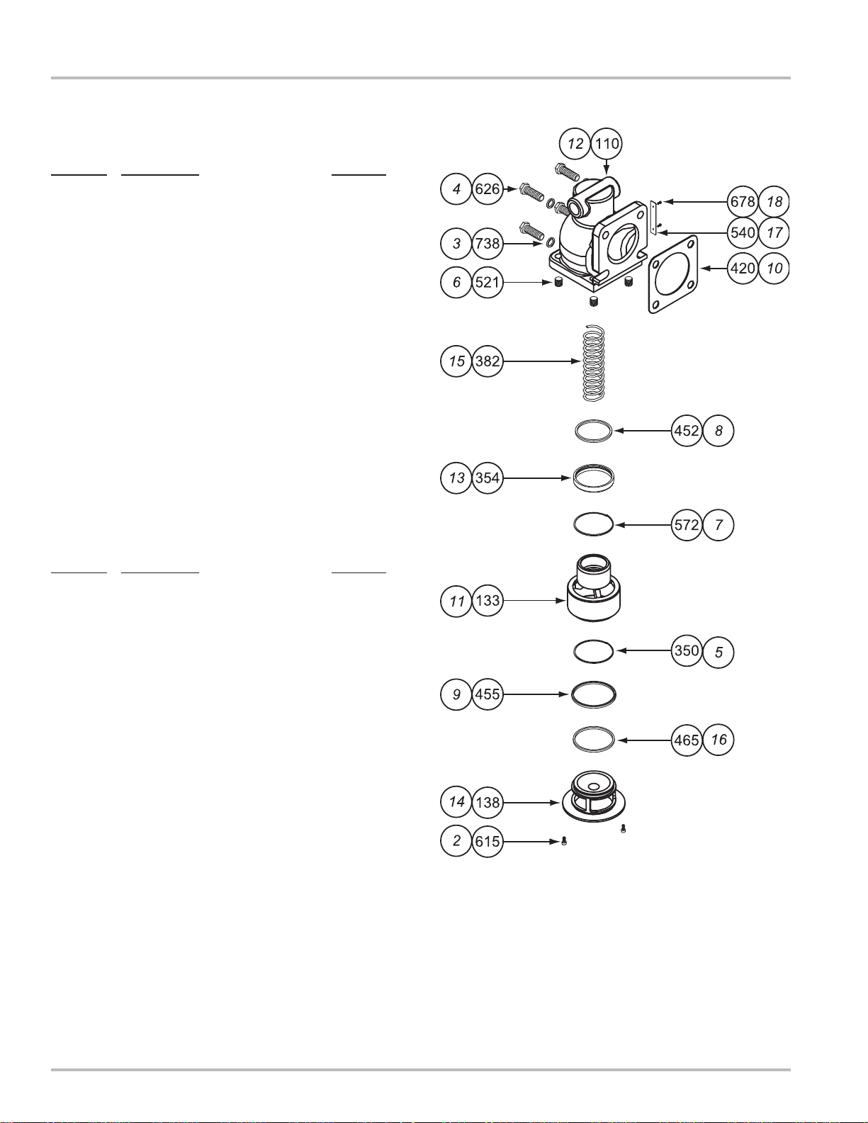
Disassembling the K-15 Valve
NOTE: Refer to the illustrated parts breakdown to the right
for Item Numbers referenced in these instructions. Item
Numbers appear in circles in the drawing.
1 Use a fixture to press and hold the valve check guide
(Item 14) in place with the compression spring (Item
15) compressed.
2 Remove the two screws (Item 2).
3 Release the pressure from the check valve guide (Item
14) until the spring (Item 15) exerts NO pressure.
4 Remove the check valve guide (Item 14), Quad Ring
(Item 16), O-Ring (Item 9) , lock ring (Item 5),
compression spring (Item 15) and piston (Item 11).
5 Remove the retainer seal and retaining ring (Items
13 & 7), and the spring seal (Item 8).
6 Leave the Heli-Coil inserts in place.
K-15 Valves
Reassembling the K-15 Valve
1 Insert the four Heli-Coil Inserts (Item 6) into the air
check housing (if they were removed).
2 Place the Quad Ring (Item 16) onto the large end of
the piston (Item 11).
3 Place the check valve guide (Item 14) into the piston
(Item 11).
4 Slide the Quad Ring (Item 16) onto the check valve
guide (Item 14) and into the groove at the flanged
end.
5 Insert the O-Ring (Item 9) with the spring facing up
onto the step on the check valve guide (Item 14).
6 Insert the lock ring (Item 5) over the O-Ring (Item 9).
7 Place the check valve guide (Item 14) into the piston
(Item 11).
8 Place the seal (Item 8) into the retainer seal (Item
13) from the end with the large chamfer and the spring
(Item 15) in the seal (Item 8).
9 Insert the retaining ring (Item 7) into the groove of
the retainer seal (Item 13) and place them into the air
check housing (Item 12) with the chamfered end
down. Carefully press in while visually inspecting
alignment. Once alignment is adjusted, press in until
seated.
10 Insert the compression spring (Item 15) into the
bottom of the air check housing (Item 12).
11 Place the piston (Item 1 1) over the compression spring
(Item 15).
12 Carefully align the piston (Item 11) with the retainer
seal (Item 13) and press down until the flange of the
check valve guide (Item 14) is flush with the housing.
This will require the use of a fixture to overcome the
pressure of the spring (Item 15).
13 While holding the check valve guide in place, insert
the two screws (Item 2) and tighten.
14 Remove the assembly from the fixture.
7
Page 8
K-30 Valves
The K-30 check valve is used on M-30 3” meters. The K30 check valve is a combination of the K-15 check valve
Model A3845 and a pipe nipple assembly. The nipple
assembly includes two flanges. One flange is 6” square
with a 3” NPT thread, the other is 4.75” square with a 3”
NPT thread. The pipe nipple is 3” in diameter and 4” in
length.
The pipe nipple assembly is included in order to mount
the check valve to the meter as the meter connection is
larger than the check valve connection.
New Installations
When ordered with a new metering system, the K-30
Check V alve is supplied mounted to the metering system.
A line must be connected to the flange on the outlet side
of the check valve. This flange connection is 3” NPT.
Finally, install a vent line from one port of the check valve
to the air eliminator. Plug the other side of the check
valve.
Retrofit Installations
Depending on the existing configuration, adding a Check
V alve may require modification of the outlet piping.
After the internal pressure is relieved from the system,
the output line can be disconnected from the output side
of the meter. In the example to the right, the output line
would be connected to the M-30 PD Meter. The check
valve assembly can then be connected to the output side
of the meter using the nipple assembly.
Use the four bolts and washers to fasten the nipple
assembly to the M-30 PD Meter. Tighten the bolts in a
crossing pattern.
Use the four bolts and washers to fasten the check valve
to the other end of the nipple assembly . The check valve
has an arrow showing the direction of flow. Ensure that
the valve is properly oriented.
Tighten the bolts in a crossing pattern. Once the check
valve is secure, the output line may be reconnected to
the output side of the check valve. The output fitting is 3”
NPT .
A vent line must be connected from one side of the check
valve to one side of the air eliminator. Plug the other side
of the check valve.
8
Page 9
Model A2817: K-7 Valve
Model No: A2811 A2817 A28171 A28172 A2821 A2826 A2831 A2851 A2862
Item No:
110 44672 49624 49624 49624 49624 49624 44672 49624 N/S
220 44674 44676 44676 44676 44677 44676 N/S 44676 45330
354 N/S* 44669 44669 44669 44669 44669 N/S 47648 N/S
389 42954 41190 45597 45598 42954 42954 42954 42954 42954
430
40430 40430 40430 40430 45818 40430 40430 N/A 45818
465 07253 07253 07253 07253 07832 07253 07832 07928 07832
572 N/A** N/A N/A N/A 06044 N/A 06044 N/A 06044
615 07364 07364 07364 07364 07364 07364 07364 07364 07364
626 07319 06991 06991 06991 06991 06991 07319 06991 07497
715 04607 04607 04607 04607 04607 04607 04607 04607 06166
Part No:
*N/S = Not for Sale **N/A = Not Applicable
Used with M-5 & M-7, 1½” & 2” meters.
Item No. Description Part No.
110 Air Check Housing 49624
220 Piston 44676
354 Seal Ring 44669
389 Compression Spring (A2817) 41190
Compression Spring (A28171) 45597
Compression Spring (A28172) 45598
430 Flange Gasket 40430
465 Quad Ring 07253
475 Name Plate N/S*
615 Screw, #6-32-3A (3) 07364
626 Screw, .375-16 x 1.25 (4) 06991
715 Flat Washer (4) 04607
Illustrated Parts Breakdown
Model A2851: K-7 Valve for NH
Used with M-5 & M-7, 1½” & 2” meters.
Item No. Description Part No.
110 Air Check Housing 49624
220 Piston 44676
354 Seal Ring Assembly 47648
389 Compression Spring 42954
465 Quad Ring 07928
475 Name Plate N/S*
615 Screw, #6-32-3A (3) 07364
626 Screw, .375-16 (4) 06991
715 Flat Washer (4) 04607
NOTE: Item 572 listed below is a retaining ring used with
Models A2821, A2831, and A2862. It is used to secure
the PTFE Seal (Item 465) on the Piston (Item 220).
3
K-7 Valve Part Numbers
9
Page 10
Illustrated Parts Breakdown
Model A3830: K-15 Valve
Used with M-15 & M-25, 3” meters.
Item No. Description Part No.
110 Air Check Housing 44118
133 Cup & Piston 41702
138 Guide 49924
350 Lock Ring 07207
354 Seal Retainer 44128
382 Compression Spring 44062
420 Flange Gasket 40871
452 Seal 07392
455 U-Cup 09014
465 Quad Ring 09158
521 Heli-Coil Insert, .5-13 x .5 (4) N/S*
540 Plate N/S
572 Retaining Ring 07391
615 Screw, #10-14 x .375 (2) 06819
626 Screw, .5-13 x 1.5 (4) 06057
678 Screw N/S
738 Flat Washer (4) 04685
Model A3845: K-15 Valve
Used with M-15 & M-25, 3” meters. (Item No. Italic)
Item No. Description Part No.
2 Screw, #10-14 x .375 (2) 06819
3 Flat Washer (4) 04685
4 Screw, .5-13 x 1.5 (4) 06057
5 Lock Ring 07207
6 Heli-Coil Insert, .5-13 x .5 (4) N/S
7 Retaining Ring 07391
8 Seal 07392
9 U-Cup 09014
10 Flange Gasket 40871
11 Cup & Piston 41702
12 Air Check Housing 44118
13 Seal Retainer 44128
14 Guide 46036
15 Compression Spring 46047
16 Quad Ring 09158
17 Plate N/S
18 Screw N/S
*N/S = Not for Sale
10
Page 11

Model A4845: K-30 Valve
Used with M-30, 3” meters.
Item No. Description Part No.
1 K-15 Air Check Valve Assy A3845
(See Page 9 for A3845 Parts.)
2 Flange, 3” N/S*
3 Pipe Nipple 07150
5 Flange, 3” NPT N/S
6 Screw, .5-13 x 2.75 (4) 06052
7 Hex Nut, .5-13 (4) 06707
8 Flange Gasket 40871
9 Flange Gasket 40704
11 Screw, .625-11 x 2.5 (4) 06466
12 Flat Washer (6) 04685
13 Flat Washer (4) 04764
14 Lock Washer (2) 06070
Illustrated Parts Breakdown
*N/S = Not for Sale
11
Page 12
A Unit of IDEX Corporation
105 Albrecht Drive
Lake Bluff, IL 60044-2242
1.800.458.5262 • 847.295.1050
Fax: 847.295.1057
www.lcmeter.com
© 2005 Liquid Controls
Pub. No. 500322
(7/13)
 Loading...