

Page 1

Page 2

CONTENTS
Specifi cations
..............................
2
Theory of Operation
Wiring
...............................................................................
4
Typical Applications
.........................................................................
..........................................................................
Analog Output Calibration
................................................
Page 3

or loop powered indicator capable of accepting magnetic pickup,
The IT 300N uses the 4-20mA loop to provide power.
Specifi cations
Supplied with 2 C size Lithium battery pack.
Voltage: 8.5 to 30 VDC
Current: Less than 5 mA
Protection: Reverse Polarity Protection on DC Power Input
Voltage: 8.5 to 30 VDC
Protection: Reverse Polarity Protection on Current Loop
Loop Burden: 8.5V maximum
tions at equipment duty cycles
Idle 2hrs/day 8hrs/day 24hrs/day
standby-operation
Battery shelf life is rated at 10 years by manufacturer
Life expectancy based on rated battery capacity at
20°C
The above table is shown with pulse output inactive.
Example: A pulse output of 0.06 sec. duration, once per
second, would derate the battery life by 20%.
5 Digits (99999), 0.35" High, Display updates once per second
with battery power, 8X per second with DC or Loop power
Rate Descriptors: /SEC, /MIN, /HR
/MIN, /HR, /DAY with "D" option
Min. Input Frequency: 0.01 Hz to 10 Hz (selectable delay of 0.1
to 99.9 seconds)*
Selectable Rate Display Damping
Totalizer Display: (selectable decimal)
8 Digits (99999999), 0.2" High
Totalizer Descriptors: GAL, LIT, FT3, M3, "blank"
GAL, BBL, MCF, M3, "blank" with "D"
option
Warning Displays: Low battery warning
The pulse output advances with the least signifi cant digit of the
totalizer or decimal multiples there of (see Pulse scale divider).
Type: Isolated photomos relay
Max. voltage (off state): 30 VDC
Current (on state): 100mA
Pulse Duration: Selectable 0.5, 0.25, 0.125, 0.0625 seconds
Pulse Scale divider (Pulscale): User selectable, ÷1, ÷10, ÷100
or OFF
NOTE: Select OFF for max. battery life.
ACCURACY
0.01% Reading, ±1 count
Temperature Drift: 50 ppm/°C Worst Case
OPERATING TEMPERATURE
-22°F (-30°C) to + 158°F (70°C)
0 - 90% Noncondensing
Frequency Range: 0 to 3500 Hz
Trigger Sensitivity: 10 mV p-p
Over Voltage Protected: ± 30 VDC
OPTO-ISOLATED DC PULSE INPUT
High (logic 1): 4-30 VDC
Low (logic 0): Less Than 1 VDC
Minimum Current: .5 mA
Hysteresis: 0.4 VDC
Frequency Range: 0 to 5 kHz
Min. Pulse Width: 0.1 msec
Internal Pullup Resistor: 100 KΩ to +3.6 VDC
High (logic 1): Open or 4-30 VDC
Low (logic 0): Less Than .5 VDC
Internal Switch Debounce Filter: 0 to 40 Hz
battery life.
Internal Pullup Resistor: 100 KΩ to +3.6 VDC
High (logic 1): Open or 4-30 VDC
Low (logic 0): Less Than .5 VDC
Minimum On : 25 msec
battery life.
Range: 0.001 to 99999999
Decimal Point Locations: XXXX.XXXX to XXXXXXXX
20 Point Linearization Option
This feature allows the user to enter 20 different frequencies
with 20 different corresponding K-Factors to linearize non linear
signals.
ANALOG OUTPUT:
Type: 4-20 mA follows rate display, Two wire hookup
Accuracy: 0.025% Full Scale at 20° C
Temperature Drift: 50 ppm/°C Typical
Reverse Polarity Protected
Update Rate: 8 times/second
The IT 300N uses the 4-20 mA loop power as its primary
Setup Information: Stored in fl ash memory
Totalizer: Stored in battery backed RAM but can be saved to
fl ash memory by operator for recall after battery change out.
* Slow input pulse rates, large delay setting and internal math
operations may delay the update rate of information.
Idle 2hrs/day 8hrs/day 24hrs/day
standby-operation
Page 4

BATTERY INSTALLATION and REPLACEMENT
All meter mounted confi gured IT 300N models are shipped without the batteries installed. When using external
To install the batteries, begin by locating the battery holder. This requires opening the enclosure cover and removing
the IT 300N to expose the battery holder.
The plus terminal of the battery is marked with a (+) symbol stamped into the battery holder. Be sure to install the
The IT 300N has a battery monitor feature which illuminates when the lithium battery voltage approaches its end
of life. A descriptor, “BAT”, illuminates when the battery voltage falls below this predetermined value. The low bat-
tery detector operates correctly with all power options.
The battery, or batteries, should be replaced within several weeks of the fi rst occurrence of low battery warning,
(left arrow) key to save the totalizer. The display will show "
If the display starts to fl ash after the "
to fl ash memory. At this point you must record the totalizer and setup information and re-enter the setup data after
the new battery(ies) is(are) installed.
6 5 4 3 2 1
Rear View
Battery
789101112
BATPAC
K
Connector
Jumper momentarily to reset unit to factory default values.
Page 5
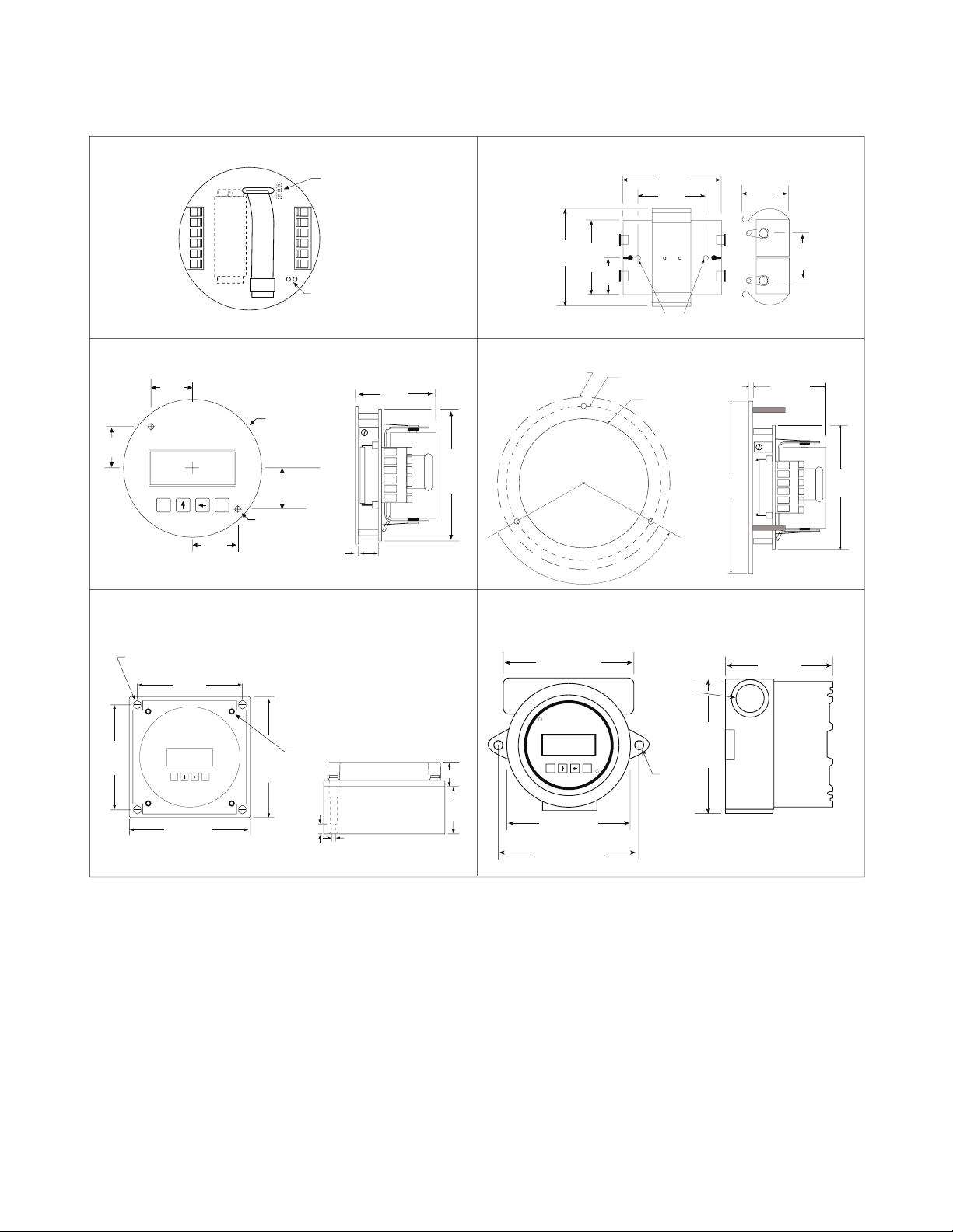
4.63
(117)
3/4 NPT
(2) HLS
5.00
(127)
5/16
4.25
(108)
5.25
(133)
E
M
5.00
(127)
To access terminals, unscrew cover and loosen 2 panel screws.
(If screws are removed, spacers may drop out.) Terminals are on
bottom side of PC board.
4.92
(125)
4.92
(125)
4.21
(107)
4.21
(107)
Mounting holes molded
directly under cover screws.
Max. screw head .29"
(Typ. 4 places)
TOP VIEW
PANEL INSTALLED
E
M
.98
(25)
1.97
(50)
.18
(5)
.43
(11)
SIDE VIEW
To access terminals,
remove cover and 4 panel
screws. Terminals are on
bottom side of PC board.
Panel Screws (4 places)
IT 300N-3IT 300N-2 & IT 300N-5
INSTALLATION
3.062" (77.77)
Dia. Cutout
3.582" Dia. Bolt Circle
.125" Holes to be 120
° Apart
Outside Dotted Line Shows
Outside Panel Dimension
(4.00" Diameter)
120°
.10
(2.54)
4.00
(101.6)
1.7
(43)
2.875
(73)
IT 300N-0 IT 300N-1
E
M
3.0120 DIAMETER
.900
(22.8)
.992
(25.2)
Mounting holes
.125 Drill (2 places)
.375 Nylon Spacer
Supplied
1.8
(46)
2.875
(73)
.10
(2.5)
.375
(9.5)
.900
(22.8)
.992
(25.2)
6 5 4 3 2 1
Rear View
Battery
Jumper Momentarily
To Initialize
789101112
BATPACK
Connector
BATPACK
2.093
(53)
1.75
(44.5)
1.625
(41)
.812
(20.6)
2.125
(54)
1.10
(28)
1.0
(25.4)
Mounting
Holes
Fig 1
Page 6

THEORY OF OPERATION
T
otal
Sum of Input Pulses
C
TYPICAL APPLICATIONS
options may be intermixed in many ways to solve common applications. The isolated pulse output may be freely
terminals (+) 12 and (-) 11. Accidental wiring to (+) 12 and (-)6 should be avoided since excessive current
fl ow may result with power option "C".
cidental connections to earth may result in erroneous operation of the analog output and/or excessive
current fl ow with power option "C".
eration of the analog output and/or excessive current fl ow with power option "C".
WIRING
C
x
Ti
Where
60 for rate per minute read out
3600 for rate per hour read out
86400 for rate per day read out
“D” option Only
20 Point Linearization Option:
A 20 point linearization table is used to construct a curve describing the relationship of K-Factor and input frequency.
The measured input frequency is used to access the table. A linear interpolation of adjacent point pairs is used to
arrive at the K-Factor at that input frequency. The fl ow rate and total are then computed based upon the K-Factor
for that measurement sample.
For best performance and resolution choose as many decimal places as possible in the K-Factor.
Example: Enter a K-Factor of 1 as 1.000.
Remote
Reset Switch
12 VDC
Power
Supply
+
-
1 Mag Input 1
2 Mag Input 2
3 Shield/Common
4 Reset Input
5 Contact Input
6 Common/ DC In (-)
Turbine Meter with
Mag Pickup
6 5 4 3 2 1
MAG INPUT / DC POWERED
DC In (+) 12
Not Used (-) 11
Opto Input (+) 10
Opto Input (-) 9
Opto Out (+) 8
Opto Out (-) 7
789101112
KEP
115-12
or
Ext. Battery
(Power option
A
or B)
Flowmeter with
Switch Closure Output
DC In (+) 12
Not Used 11
Opto Input (+) 10
Opto Input (-) 9
Opto Out (+) 8
Opto Out (-) 7
1 Mag Input 1
2 Mag Input 2
3 Shield/Common
4 Reset Input
5 Contact Input
6 Common/ DC In (-)
6 5 4 3 2 1
CONTACT INPUT / PULSE OUTPUT / BATTERY POWERED
123456
789101112
(Power option
A
or B)
Remote
Reset Switch
1 Mag Input 1
2 Mag Input 2
3 Shield/Common
4 Reset Input
5 Contact Input
6 Common/ DC In (-)
Turbine Meter with
Mag Pickup
6 5 4 3 2 1
MAG INPUT / BATPACK POWERED
DC In (+) 12
Not Used(-) 11
Opto Input (+) 10
Opto Input (-) 9
Opto Out (+) 8
Opto Out (-) 7
789101112
BATPACK PLUGIN
CONNECTOR
BATPACK
(Power option
or B)
(Power option C or
AC)
Turbine Meter with
Mag Pickup
1 Mag Input 1
2 Mag Input 2
3 Shield/Common
4 Reset Input
5 Contact Input
6 Common
6 5 4 3 2 1
+
-
Strip Chart
Recorder
MAG INPUT / 4-20 mA LOOP POWERED
4-20mA (+)(+) 12
4-20mA (-) 11
Opto Input (+) 10
Opto Input (-) 9
Opto Out (+) 8
Opto Out (-) 7
789101112
24 VDC
Power
Supply
+
-
Page 7

DEFINITIONS
key while the unit is running to save the total value. The display will show
the battery(ies)
key to step to the next digit to the left. Press the
key to enter the 5 digit code. If the entered
code is correct, the display will advance to the next menu prompt (CLr tot). If incorrect, the display will return
to the run mode.
key to clear the total and return to the run mode. Press
the
key to skip and advance to the next menu selection.
of this decimal automatically limits the number of decimal locations allowable in the rate and total to acceptable
key to move the decimal. Press the
key to select the displayed decimal location.
For best performance and resolution choose as many decimal places as possible in the K-Factor.
Example: Enter a K-Factor of 1 as 1.000.
/
tion. The
linearization selection is recommended for fl ow meters whose K-factors change with different
fl ow rates. This selection allows users to enter up to 20 different frequencies with 20 corresponding K-factors for
different fl ow rates. The
setting is used for fl ow meters whose output is linear over its' entire operating
fl ow range. Press the
key to enter the displayed factor type.
/
for
to skip and keep the existing values.
for the fl ow sensor. The pulses/unit volume is implied by the totalizer descriptor when a descriptor is used. The
GAL pulses/gallon GAL pulses/gallon
LIT pulses/liter BBL pulses/BBL
FT3 pulses/ft3 MCF pulses/MCF
M3 pulses/M3 M3 pulses/M3
Factors from 0.0001 to 99999999 may be used. A "0" value for the factor is not allowed and the unit will default
to "1" in LSD if a "0" entry is attempted . The factor is displayed on the subsidiary (lower) display. Press the
key to step to the next digit to the left. Press the
key to enter the
displayed factor.
the 20 points (#). Press the
key to step to the next digit to the left.
key to enter the desired frequency for point #.
key to step to the next digit to the left. Press
the
key to enter the desired factor for point #.
The display will advance to the next point (Fr#) after each entry of the Fr & Fac until all 20 points are com-
Page 8

6
DEFINITIONS
and will scale the totalizer display accordingly. (i.e. if the tdec is set in the tenths position (1234567.8), 100 will be
displayed as 100.0). The location of the decimal point allows for greater resolution of both the totalizer display
and the pulse output. The pulse output advances at a rate dependent on the least signifi cant digit of the total-
of totalizer decimal locations allowable is reduced with each decimal place added to the factor decimal. Press
the
key to move the decimal. Press the
key to enter the displayed decimal location.
Note:
The selection of the factor decimal point limits the available selections for the number of decimal
tor. Press the
key to enter the selected descriptor.
or seconds (
shown on the main (upper) display. Press the
key to enter the
displayed scale setting.
A rate descriptor corresponding to the above choice will be illuminated on the display.
4 places (.1234). However, the number of ratemeter decimal locations allowable is reduced with each decimal
key to move the decimal. Press the
key to enter the displayed
decimal location.
Note:
The fl ow rate indicator will fl ash “99999” if the computed fl ow rate exceeds the 99999
display capability of the indicator. Choose a new decimal point location to avoid this.
NORMALIZING FACTOR - Normalizes (averages or dampens) the fl ow rate data being received. Enter a
value from 0 to 9. Higher settings provide more normalizing (averaging) for a more stable display. Derived
from the equation:
("NOR" + 1)
are not detected within this "window", the rate will display 0. The display will update once every second as
key to step to the next digit to the left. Press the
key
to enter the displayed delay value.
output 4mA. Press the
key to step to the next digit to the left. Press
the
key to enter the displayed out lo value.
will output 20 mA. Press the
key to step to the next digit to the left.
key to enter the displayed out hi value.
Page 9

DEFINITIONS
the selected divider. The pulse out can be divided by 1 (
the divider set at 1, the unit will give a pulse out for every increment of the LSD displayed.
does not exceed the maximum rate of the pulse output. If the pulse output
sage “E PULSE”. Press the “E” key to return to the run mode.
or 0.0625 (8Hz). This menu item is skipped if
is turned off.
to gain access to the menu when the unit is locked. Press the
key
to step to the next digit to the left. Press the
key to enter the displayed code.
Record this number for later use! LOCK CODE:
____________________
key to enter
the displayed selection.
Page 10

TO
CLR ToT
CLEAR
TO
ACT
OR
ACT
OR
ent Code
correct
20poInt
ACT
OR
TYPE
20poInt
lInear
lInear
selected
20poInt
selected
#####
for POINT
(Fr0-Fr19)
ACT
OR for
(F
AC0-F
AC19)
0
# = 19
SET pnts
No
SET
20PT
selected
No
selected
The
prompt will only appear if
key to choose YES or NO.
to the menu.
key to increment each individual digit of the code.
key to advance to the next digit.
", if not, display returns
to run mode
key to step the factor decimal to the desired location.
to skip and keep the existing location
For best performance and resolution choose as many decimal places as
key to choose factor type (
or
key to increment each individual digit of the factor for point #.
key to advance to the next digit.
key to increment each individual digit of the frequency for
key to advance to the next digit.
Frequency/factor point pairs must be entered in ascending order of fre-
quency
The
prompt will only appear if
ordered without the 20 point linearization option.
key to increment each individual digit of the factor.
key to advance to the next digit.
Page 11

When option "D" (rate per day) is ordered; selections are:
GAL, BBL, MCF, M3, "blank"
When option "D" (rate per day) is ordered; selections are:
min, sec, days
value).
This will only display on units with Analog Output.
This will only display on units with Analog Out-
output.
This will not display if Pulse Out is turned OFF.
r SCALE
TO
TA
SCALE
(ratemeter)
NNIN
HRS
)
GAL
(BBL, MCF)
R DECLoC
oUT HI
Pul scale
OUT LOW
(4mA)
OUT HIGH
(20mA)
SCALER
(divider)
D100D100D100
0.1to 99.9
.5
p uuidth
.5
.25
.125
.0625
(seconds)
TION
Continued From Previous Page
CODE
loC UnIt
TURN LOCK
ON or OFF
no
TO
TA
OR
TION
Page 12

A suitable pulse producing device or fl ow meter is wired to one of the three pulse inputs provided on the IT 300N.
terminals 5 and 6. Any high level, DC pulse type may be connected to terminals 9(-) and 10(+).
The fl ow totalizer is updated once per second* with battery power, 8 times per second with DC or loop power. If no
The fl ow total may be cleared by the front panel switch sequence or by a contact closure on the remote reset ter-
To reset the unit from the front panel, the following key sequence is required:
“CLr tot” will be displayed (if the panel lock is on, the display will prompt "
Enter the proper code to advance to the
prompt)
To clear the total. Unit will return to operation
The fl ow rate indicator will measure the fl ow rate once every second* with battery power, 8 times per second with
The analog output will be scaled based on the user selected zero and full scale and the measured fl ow rate. The
analog output is updated at the same time as the rate display.
The pulse output updates at the same rate as the total display in accordance with the instrument setup of pulse
scaling.
* Slow input pulse rates, large delay setting and internal math operations may delay the update rate of information..
A faster update rate occurs when the unit is loop powered or externally powered.
Page 13

The IT 300N is provided with extensive self checking which assists the user in the location of setup entry errors
and in reporting malfunctions or unusual operating conditions. When an error occurs, the display will fl ash. Press
any key to see the error message corresponding to the error that has occurred. Press any key again to acknowl-
edge the error. (If the error can be eliminated by a change of setup values, the unit will automatically advance to
the MENU so that the appropriate setup changes can be made).
Table - 2 illustrates the warning message, problem, and recommended corrective actions.
WARNING MESSAGE CAUSE CORRECTIVE ACTION
Rate Low set Set Rate Hi greater
higher than Rate Hi than Rate Lo
Factor = 0 Set in correct Factor
Total rollover None required
Rate exceeds 99999 Use lower rate dec point
Pulse out Overfl ow Use different pulse scaler or
totalizer decimal point
Save to fl ash Write down displayed total and
memory failed setup values if you are changing
the battery. If total wasn't saved,
it will display an arbitrary total
when new battery is installed. In
this case, reset the total to 0 and
check the setup information.
ANALOG OUTPUT CALIBRATION
the 4-20 mA has been accurately set to 4.000 and
20.000 mA by the factory. No calibrationshould be required.
The 4-20 mA output may be verifi ed periodically by installing a digital milliamp meter(DMM) in series with the
analog output and simulating a full scale or over range fl ow rate.
with a power supply (8.5 to 30 volts DC) to TB12 (+) and TB11 (–). The output should read 4.000 ma (± 0.005).
down until the output reads 20.000 ma (± 0.005). Press "E" and the unit will return to the "RUN" mode.
Page 14

Page 15

 Loading...