

Page 1
SRW2008/SRW2008P/SRW2008MP
Page 2
WebView Switches
Copyright and Trademarks
Specifications are subject to change without notice. Linksys is a registered trademark or trademark of Cisco
Systems, Inc. and/or its affiliates in the U.S . and certain other countries. Copyright © 2006 Cisco Systems, Inc . All
rights reserved. Other brands and product names are trademarks or registered trademarks of their respective
holders.
WARNING: This product contains chemicals, including lead, known
to the State of California to cause cancer, and birth defects or other
reproductive harm. Wash hands after handling.
How to Use this User Guide
The User Guide to the WebView Switches has been designed to make understanding networking with the switch
easier than ever. Look for the following items when reading this User Guide:
This checkmark means there is a note of interest and
is something you should pay special attention to while
using the Switch.
This exclamation point means there is a caution or
warning and is something that could damage your
property or the Switch.
This question mark provides you with a reminder about
something you might need to do while using the Switch.
In addition to these symbols, there are definitions for technical terms that are presented like this:
word: definition.
Also, each figure (diagram, screenshot, or other image) is provided with a figure number and description, like
this:
Figure 0-1: Sample Figure Description
Figure numbers and descriptions can also be found in the “List of Figures” section.
SRW2048-UG-61006 RR
Page 3

WebView Switches
Table of Contents
Chapter 1: Introduction 1
Welcome 1
What’s in this User Guide? 3
Chapter 2: Getting to Know the Switch 4
SRW2048 4
SRW2024 6
SRW2016 8
SRW248G4 10
SRW224G4 12
Chapter 3: Connecting the Switch 14
Overview 14
Before You Install the Switch... 15
Placement Options 16
Connecting the Switch 17
Chapter 4: Using the Console Interface for Configuration 18
Overview 18
Configuring the HyperTerminal Application 18
Connecting to the Switch through a Telnet Session 19
Configuring the Switch through the Console Interface 20
Chapter 5: Using the Web-based Utility for Configuration 32
Overview 32
Accessing the Web-based Utility 32
Setup Tab - Summary 33
Setup Tab - Network Settings 34
Setup Tab - Time 35
Port Management Tab - Port Settings 36
Port Management Tab - Link Aggregation 39
Port Management Tab - LACP 40
VLAN Management Tab - Create VLAN 41
VLAN Management Tab - Port Setting 41
VLAN Management Tab - Ports to VLAN 42
VLAN Management Tab - VLAN to Ports 43
Page 4

WebView Switches
VLAN Management Tab - GVRP 44
Statistics Tab - RMON Statistics 45
Statistics Tab - RMON History 46
Statistics Tab - RMON Alarm 48
Statistics Tab - RMON Events 50
Statistics Tab - Port Utilization 51
Statistics Tab - 802.1x Statistics 51
Statistics Tab - GVRP Statistics 52
ACL Tab - IP Based ACL 53
ACL Tab - MAC Based ACL 55
Security Tab - ACL Binding 56
Security Tab - RADIUS 57
Security Tab - TACACS+ 58
Security Tab - 802.1x Settings 59
Security Tab - Port Security 60
Security Tab - Multiple Hosts 61
Security Tab - Storm Control 62
QoS 62
QoS Tab - CoS Settings 63
QoS Tab - Queue Settings 64
QoS Tab - DSCP Settings 64
QoS Tab - Bandwidth 65
QoS Tab - Basic Mode 65
QoS Tab - Advanced Mode 66
Spanning Tree 68
Spanning Tree Tab - STP Status 68
Spanning Tree Tab - Global STP 69
Spanning Tree Tab - STP Port Settings 70
Spanning Tree Tab - RSTP Port Settings 72
Spanning Tree Tab - MSTP Properties 73
Spanning Tree Tab - MSTP Instance Settings 74
Spanning Tree Tab - MSTP Interface Settings 74
Multicast Tab - IGMP Snooping 76
Multicast Tab - Bridge Multicast 77
Multicast Tab - Bridge Multicast Forward All 78
SNMP Tab - Global Parameters 78
Page 5

WebView Switches
SNMP Tab - Views 79
SNMP Tab - Group Profile 80
SNMP Tab - Group Membership 81
SNMP Tab - Communities 82
SNMP Tab - Notification Filter 83
SNMP Tab - Notification Recipient 84
Admin Tab - User Authentication 85
Admin Tab - Jumbo Frames 86
Admin Tab - Static Address 86
Admin Tab - Dynamic Address 87
Admin Tab - Logging 88
Admin Tab - Port Mirroring 89
Admin Tab - Cable Test 89
Admin Tab - Save Configuration 90
Admin Tab - Firmware Upgrade 91
Admin Tab - Reboot 91
Admin Tab - Factory Defaults 92
Admin Tab - Server Logs 92
Admin Tab - Memory Logs 93
Admin Tab - Flash Logs 93
Appendix A: About Gigabit Ethernet and Fiber Optic Cabling 94
Gigabit Ethernet 94
Fiber Optic Cabling 94
Appendix B: Windows Help 95
Appendix C: Downloading using Xmodem 96
Startup Menu Procedures 96
Appendix D: Glossary 98
Appendix E: Specifications 105
SRW2048 105
SRW2016/SRW2024 109
SRW224G4/SRW248G4 113
Appendix F: Warranty Information 117
Appendix G: Regulatory Information 118
Appendix H: Contact Information 124
Page 6

WebView Switches
List of Figures
Figure 2-1: Front Panel of the SRW2048 4
Figure 2-2: Back Panel of the SRW2048 5
Figure 2-3: Front Panel of the SRW2024 6
Figure 2-4: Back Panel of the SRW2024 7
Figure 2-5: Front Panel of the SRW2016 8
Figure 2-6: Back Panel of the SRW2016 9
Figure 2-7: Front Panel of the SRW248G4 10
Figure 2-8: Back Panel of the SRW248G4 11
Figure 2-9: Front Panel of the SRW224G4 12
Figure 2-10: Back Panel of the SRW224G4 13
Figure 3-1: Typical Network Configuration for the SRW2048 14
Figure 3-2: Attach the Brackets to the Switch 16
Figure 3-3: Mount the Switch in the Rack 16
Figure 4-1: Finding HyperTerminal 18
Figure 4-2: Connection Description 18
Figure 4-3: Connect To 18
Figure 4-4: COM1 Properties 19
Figure 4-5: Telnet Login screen 19
Figure 4-6: Switch Main Menu 20
Figure 4-7: System Configuration Menu 21
Figure 4-8: System Information Menu 22
Figure 4-9: Versions 22
Figure 4-10: General System Information 22
Figure 4-11: Management Settings Menu 23
Figure 4-12: Serial Port Configuration 23
Figure 4-13: Telnet Configuration 23
Figure 4-14: SSH Configuration 24
Figure 4-15: SSH Server Configuration 24
Page 7

WebView Switches
Figure 4-16: SSH Status 24
Figure 4-17: SSH Crypto Key Generation 25
Figure 4-18: SSH Keys Fingerprints 25
Figure 4-19: Username & Password Settings 26
Figure 4-20: Security Settings 26
Figure 4-21: SSL Certificate Generation 26
Figure 4-22: SSL Certificate 27
Figure 4-23: IP Configuration 27
Figure 4-24: IP Address Configuration 28
Figure 4-25: HTTP 28
Figure 4-26: HTTPS Configuration 28
Figure 4-27: Network Configuration 29
Figure 4-28: Ping Test 29
Figure 4-29: TraceRoute Test 29
Figure 4-30: File Management 30
Figure 4-31: Restore System Default Settings 30
Figure 4-32: Reboot System 30
Figure 4-33: Port Status 31
Figure 4-34: Port Configuration 31
Figure 5-1: Login Screen 32
Figure 5-2: Setup - Summary 33
Figure 5-3: Setup - Network Settings 34
Figure 5-4: Setup - Time 35
Figure 5-5: Port Management - Port Settings 36
Figure 5-6: Port Settings - Port Configuration Detail 37
Figure 5-7: Port Management - Link Aggregration 39
Figure 5-8: Link Aggregation - Link Aggregation Detail 39
Figure 5-9: Port Management - LACP 40
Figure 5-10: VLAN Management - Create VLAN 41
Figure 5-11: VLAN Management - Port Settings 41
Page 8

WebView Switches
Figure 5-12: VLAN Management - Ports to VLAN 42
Figure 5-13: VLAN Management - VLAN to Ports 43
Figure 5-14: VLAN to Ports - Join VLAN 43
Figure 5-15: VLAN Management - GVRP 44
Figure 5-16: Statistics - RMON Statistics 45
Figure 5-17: Statistics - RMON History 46
Figure 5-18: RMON History Table 47
Figure 5-19: Statistics - RMON Alarm 48
Figure 5-20: Statistics - RMON Events 50
Figure 5-21: RMON Events - Events Log 50
Figure 5-22: Statistics - Port Utilization 51
Figure 5-23: Statistics - 802.1x Statistics 51
Figure 5-24: Statistics - GVRP Statistics 52
Figure 5-25: ACL - IP Based ACL 53
Figure 5-26: ACL - Mac Based ACL 55
Figure 5-27: Security - ACL Binding 56
Figure 5-28: Security - RADIUS 57
Figure 5-29: Security - TACACS+ 58
Figure 5-30: Security - 802.1x Settings 59
Figure 5-31: 802.1x Settings - Setting Timer 59
Figure 5-32: Security - Port Security 60
Figure 5-33: Security - Multiple Hosts 61
Figure 5-34: Security - Storm Control 62
Figure 5-35: QoS - CoS Settings 63
Figure 5-36: QoS - Queue Settings 64
Figure 5-37: QoS - DSCP Settings 64
Figure 5-38: QoS - Bandwidth 65
Figure 5-39: QoS - Basic Mode 65
Figure 5-40: QoS - Advanced Mode 66
Figure 5-41: Advanced Mode - Out of Profile DSCP 66
Page 9

WebView Switches
Figure 5-42: Advanced Mode - Policy Name 66
Figure 5-43: Advanced Mode - New Class Map 67
Figure 5-44: Advanced Mode - New Aggregate Policer 67
Figure 5-45: Spanning Tree - STP Status 68
Figure 5-46: Spanning Tree - Global STP 69
Figure 5-47: Spanning Tree - STP Port Settings 70
Figure 5-48: Spanning Tree - RSTP Port Settings 72
Figure 5-49: Spanning Tree - MSTP Properties 73
Figure 5-50: Spanning Tree - MSTP Instance Settings 74
Figure 5-51: Spanning Tree - MSTP Interface Settings 74
Figure 5-52: Multicast - IGMP Snooping 76
Figure 5-53: Multicast - Bridge Multicast 77
Figure 5-54: Multicast - Bridge Multicast Forward All 78
Figure 5-55: SNMP - Global Parameters 78
Figure 5-56: SNMP - Views 79
Figure 5-57: SNMP - Group Profile 80
Figure 5-58: SNMP - Group Membership 81
Figure 5-59: SNMP - Communities 82
Figure 5-60: SNMP - Notification Filter 83
Figure 5-61: SNMP - Notification Recipient 84
Figure 5-62: Admin - User Authentication 85
Figure 5-63: Admin - Jumbo Frames 86
Figure 5-64: Admin - Static Address 86
Figure 5-65: Admin - Dynamic Address 87
Figure 5-66: Admin - Logging 88
Figure 5-67: Admin - Port Mirroring 89
Figure 5-68: Admin - Cable Test 89
Figure 5-69: Admin - Save Configuration 90
Figure 5-70: Admin - Firmware Upgrade 91
Figure 5-71: Admin - Reboot 91
Figure 5-72: Admin - Factory Defaults 92
Page 10

WebView Switches
Figure 5-73: Admin - Server Logs 92
Figure 5-74: Admin - Memory Logs 93
Figure 5-75: Admin - Flash Logs 93
Figure C-1: Auto-Boot Message 96
Figure C-2: Startup Menu 96
Figure C-3: Send File 97
Figure C-4: Download 97
Page 11

WebView Switches
Chapter 1: Introduction
Welcome
This guide covers five product models.
• SRW2048 - 48-port 10/100/1000 Gigabit Switch with WebView.
Includes 48 10/100/1000 RJ-45 ports and 4 shared SFP (MiniGBIC) slots.
• SRW2024 - 24-Port 10/100/1000 Gigabit Switch with WebView.
Includes 24 10/100/1000 RJ-45 ports and 2 shared SFP (MiniGBIC) slots.
• SRW2016 - 16-Port 10/100/1000 Gigabit Switch with WebView
Includes 16 10/100/1000 RJ-45 ports and 2 shared SFP (MiniGBIC) slots.
• SRW248G4 - 48-port 10/100 + 4-Port Gigabit Switch with WebView
Includes 48 10/100 RJ-45 ports and 4 10/100/1000 RJ-45 ports and 2 shared SFP (MiniGBIC) slots.
• SRW224G4 - 24-port 10/100 + 4-Port Gigabit Switch with WebView
Includes 24 10/100 RJ-45 ports and 4 10/100/1000 RJ-45 ports and 2 shared SFP (MiniGBIC) slots.
For the purpose of this manual, whenever a feature applies to all models, the name WebView Switch will be
referenced. If a specific model number is mentioned, then the feature is specific to that model.
The Linksys WebView Managed Switch allows you to expand your network securely. Configuration of the switch
is secured using SSL for Web access. User control is secured using 802.1x security using a RADIUS
authentication mechanism and can also be controlled using MAC-based filtering.
Extensive QoS features makes the solution ideal for real-time applications like Voice and Video. The 4 priority
queues together with the Weighted Round Robin and Strict Priority scheduling techniques facilitate efficient
coexistence of real-time traffic with data traffic allowing them each to meet their QoS needs. Individual users or
applications can be prioritized above others using various Class of Service options - by port, layer 2 priority
(802.1p), and Layer 3 priority (TOS or DSCP). Intelligent Broadcast, and Multicast storm control minimizes and
contain the effect of these types of traffic on regular traffic. IGMP Snooping limits bandwidth-intensive video
traffic to only the requestors without flooding to all users. Incoming traffic can be policed and outgoing traffic can
be shaped allowing you to control network access and traffic flow.
Chapter 1: Introduction
Welcome
1
Page 12

WebView Switches
There are features that allow you to expand and grow your network of switches. Link aggregation allows multiple
high-bandwidth trunks between switches to be setup. This also provides a level of reliability in that the system
continues to operate if one of the links break. Spanning Tree (STP), Fast Linkover, Rapid Spanning Tree (RSTP) and
Multiple Spanning Tree (MSTP) allows you to build a mesh of switches increasing the availability of the system.
The rich management functionality of the WebView switches includes SNMP, RMON, Telnet, and HTTP
Management options, allowing you to flexibly integrate and manage these devices in your network.
Chapter 1: Introduction
Welcome
2
Page 13

WebView Switches
What’s in this User Guide?
This user guide covers the steps for setting up and using the Switch.
• Chapter 1: Introduction
This chapter describes the Switch’s applications and this User Guide.
• Chapter 2: Getting to Know the Switch
This chapter describes the physical features of the Switch.
• Chapter 3: Connecting the Switch
This chapter explains how to install and connect the Switch.
• Chapter 4: Using the Console Interface for Configuration
This chapter instructs you on how to use the Switch’s console interface when you configure the Switch.
• Chapter 5: Using the Web-based Utility for Configuration
This chapter shows you how to configure the Switch using the Web-based Utility.
• Appendix A: About Gigabit Ethernet and Fiber Optic Cabling
This appendix gives a general description of Gigabit Ethernet and fiber optic cabling.
• Appendix B: Windows Help
This appendix describes how you can use Windows Help for instructions about networking, such as installing
the TCP/IP protocol.
• Appendix C: Downloading using Xmodem
This appendix describes how you can download software into the Switch using Xmodem.
• Appendix D: Glossary
This appendix gives a brief glossary of terms frequently used in networking.
• Appendix E: Specifications
This appendix provides the Switch’s technical specifications.
• Appendix F: Warranty Information
This appendix supplies the Switch’s warranty information.
• Appendix G: Regulatory Information
This appendix supplies the Switch’s regulatory information.
• Appendix H: Contact Information
This appendix provides contact information for a variety of Linksys resources, including Technical Support.
Chapter 1: Introduction
What’s in this User Guide?
3
Page 14
WebView Switches
Chapter 2: Getting to Know the Switch
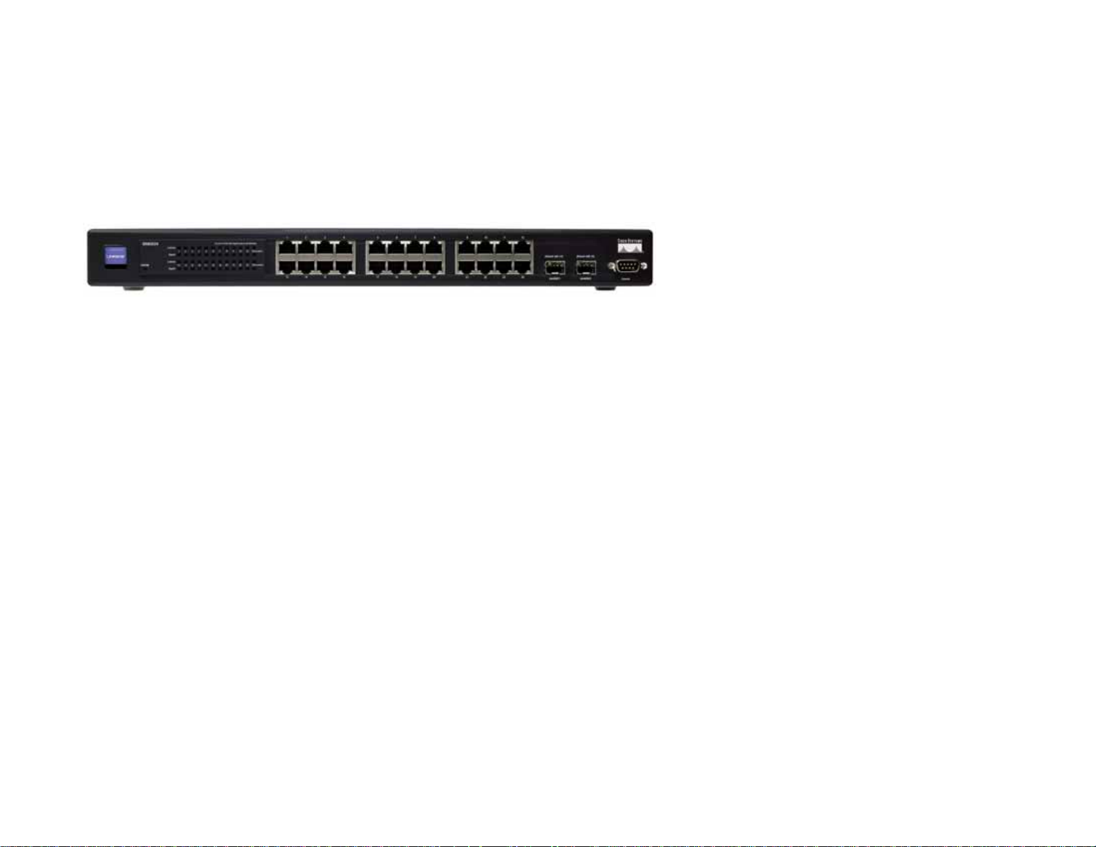
SRW2048
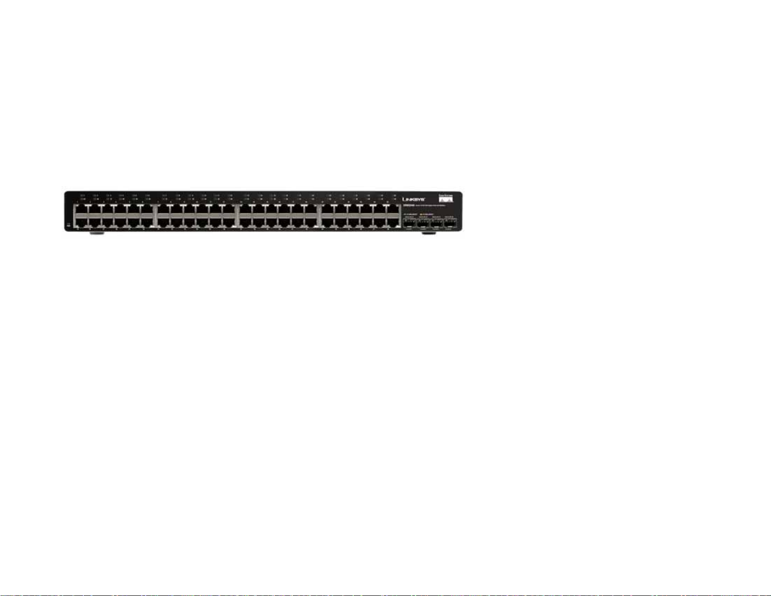
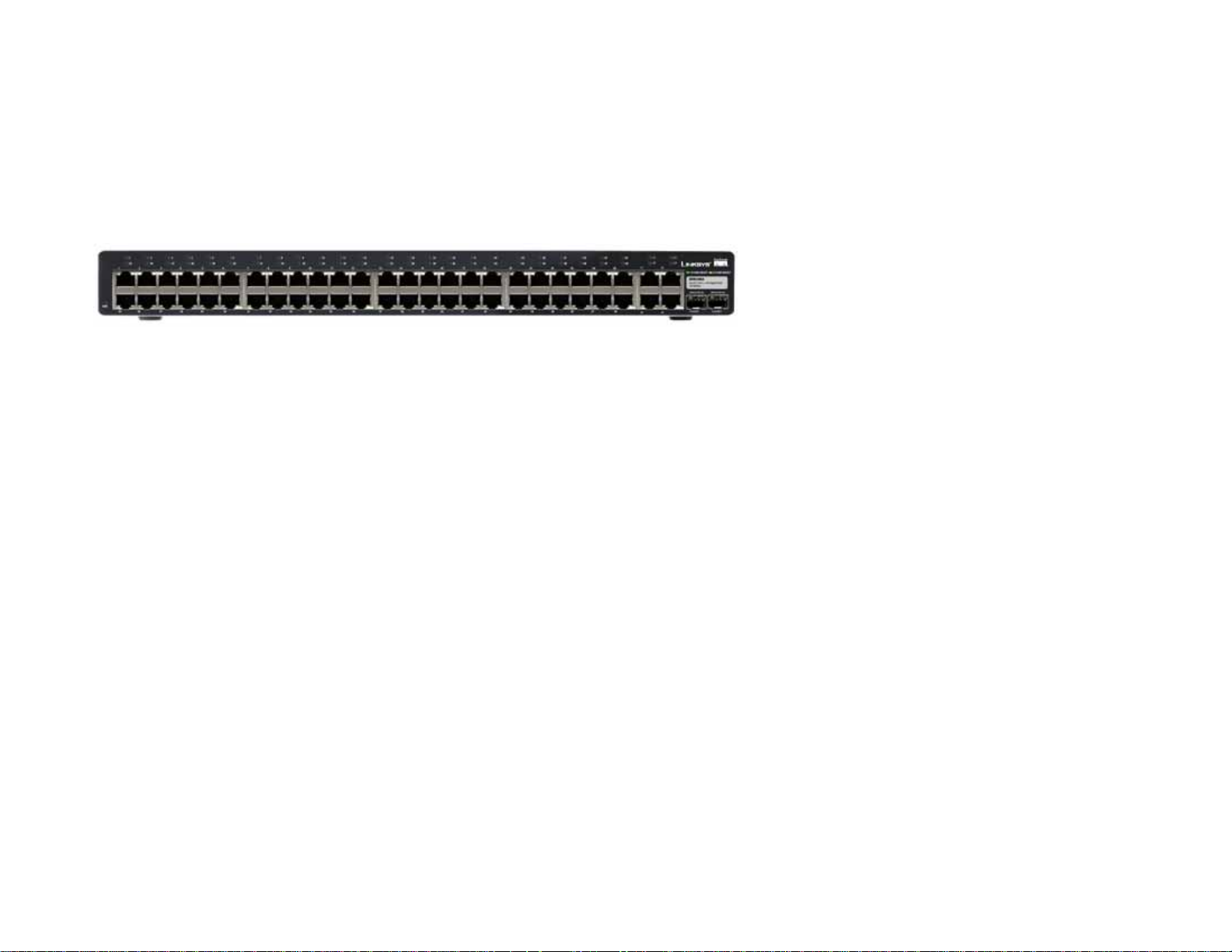
Front Panel
The Switch's LEDs and ports are located on the front panel.
Figure 2-1: Front Panel of the SRW2048
LEDs
PWR Green. The PWR LED lights up to indicate that the Switch is powered on.
Link/Act (1-48) Green. The LED lights up green to indicate a functional 10/100Mbps network link through
the corresponding port (1 through 48) with an attached device. It flashes to indicate that
the Switch is actively sending or receiving data over that port.
Orange. The LED lights up orange to indicate a 1000Mbps connection on the corresponding
port (1 through 48) with an attached device. It flashes to indicate that the Switch is actively
sending or receiving data over that port.
Ports
1-48 The Switch is equipped with 48 auto-sensing, Ethernet network ports, which use RJ-45
connectors. The Fast Ethernet ports support network speeds of 10Mbps, 100Mbps, or
1000Mbps. They can operate in half and full-duplex modes. Auto-sensing technology
enables each port to automatically detect the speed of the device connected to it (10Mbps,
100Mbps, or 1000Mbps), and adjust its speed and duplex accordingly.
Chapter 2: Getting to Know the Switch
SRW2048
4
Page 15
WebView Switches
miniGBIC 1-4 The miniGBIC (gigabit interface converter) port is a connection point for a miniGBIC
expansion module, so the Switch can be uplinked via fiber to another switc h. The MiniGBIC
port provides a link to a high-speed network segment or individual workstation at speeds
of up to 1000Mbps.
Use the Linksys MGBT1, MGBSX1, or MGBLH1 miniGBIC modules with the Switch. The
MGBSX1 and the MGBLH1 require fiber cabling with LC connectors, while the MGBT1
requires a Category 5e Ethernet cable with an RJ-45 connector.
Table 1: SRW2048 Shared Port Mapping
miniGBIC Port Standard Port
NOTE: On the SRW2048, MiniGBIC ports are shared
with standard ports. If a miniGBIC port is used, then
miniGBIC 1 Port 23
miniGBIC 2 Port 24
the shared standard port on the Switch cannot be
used. See "T able 1:SRW2048 Shared Port Mapping"
for port mapping details of the SRW2048 Switch.
miniGBIC 3 Port 47
miniGBIC 4 Port 48
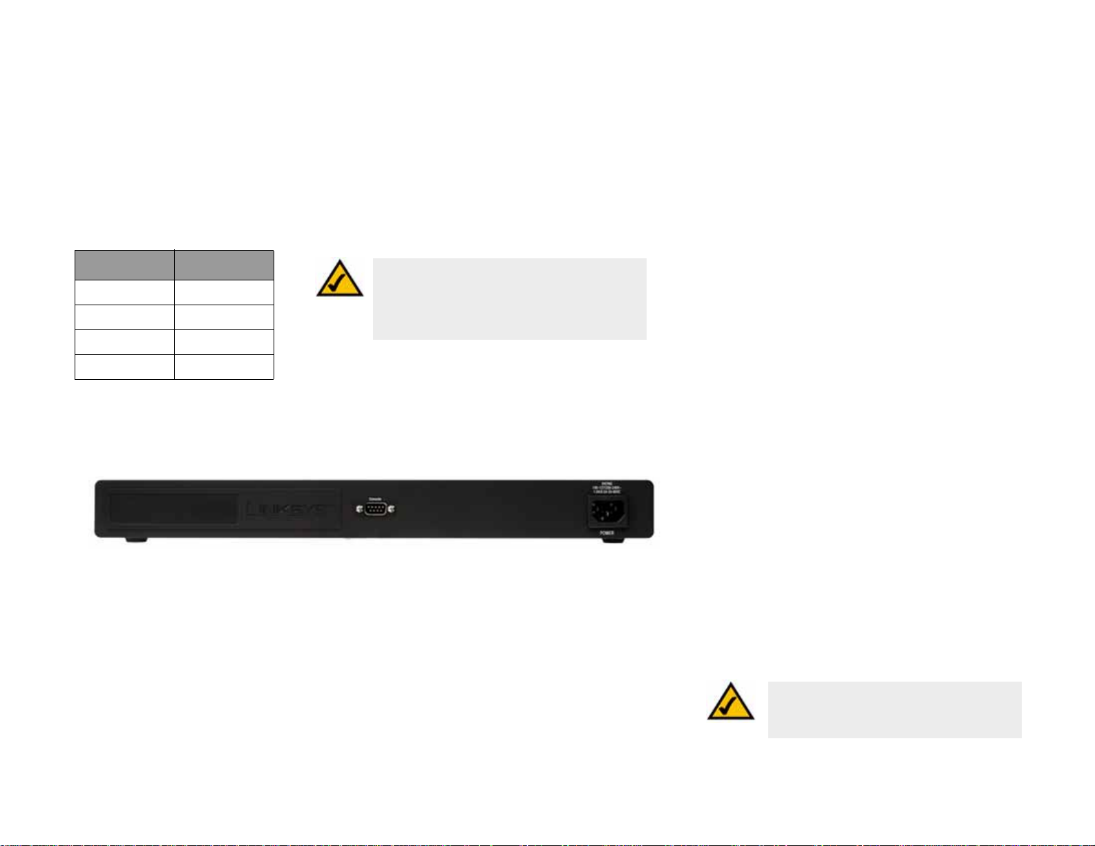
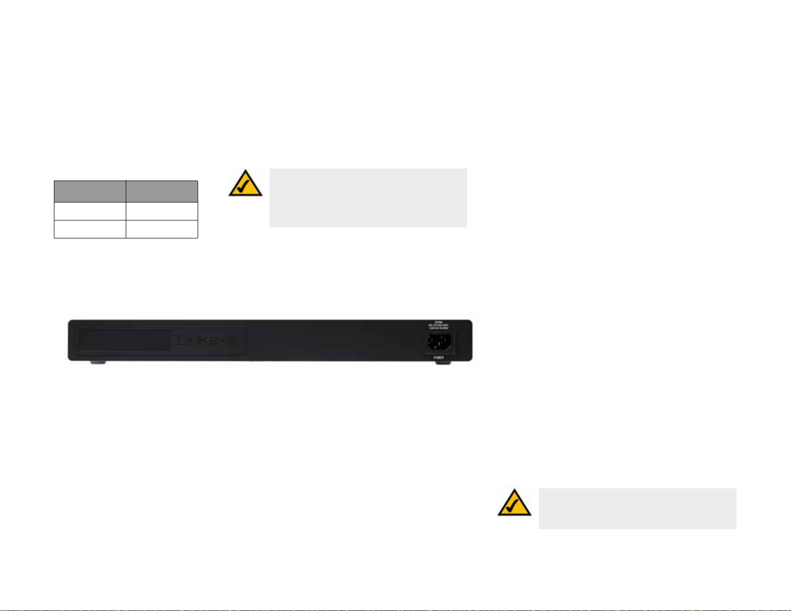
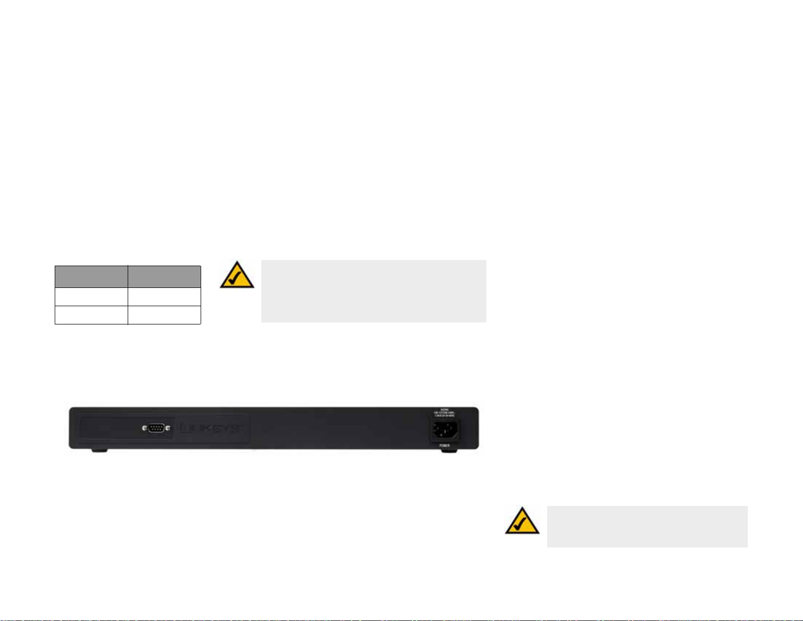
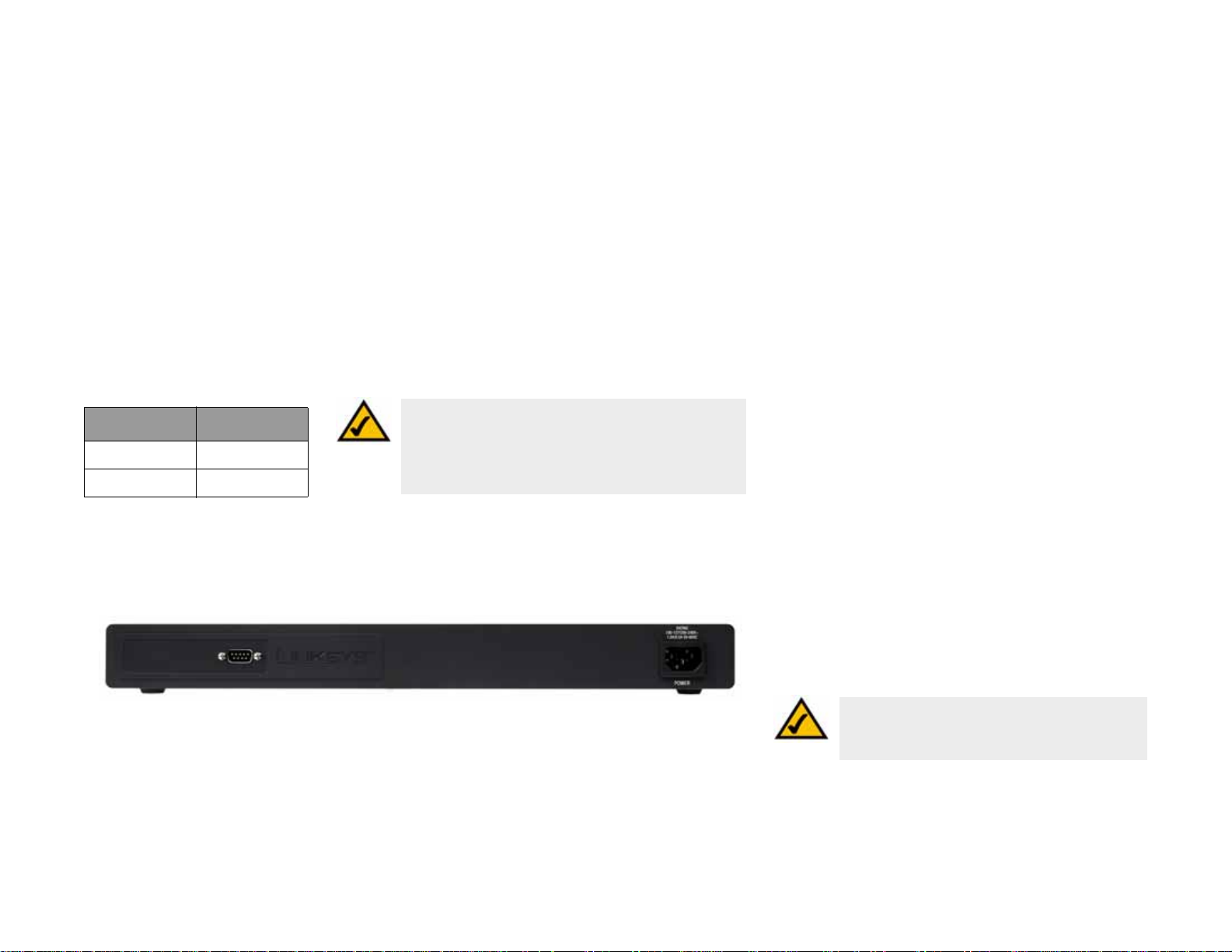
Back Panel
The power port is located on the back panel of the Switch.
Figure 2-2: Back Panel of the SRW2048
Console The Console port is where you can connect a serial cable to a PC’s serial port for
configuration using your PC’s HyperTerminal program. Refer to Chapter 4: Using the
Console Interface for Configuration for more information.
Power The Power port is where you will connect the power cord.
NOTE: If you need to reset the Switch, unplug
the power cord from the back of the Switch.
Wait a few seconds and then reconnect it.
Chapter 2: Getting to Know the Switch
SRW2048
5
Page 16
WebView Switches
SRW2024
Front Panel
The Switch's LEDs and ports are located on the front panel.
Figure 2-3: Front Panel of the SRW2024
LEDs
SYSTEM Green. The SYSTEM LED lights up to indicate that the Switch is powered on.
Link/Act (1-24) Green. The LED lights up green to indicate a functional 10/100Mbps network link through
the corresponding port (1 through 24) with an attached device. It flashes to indicate that
the Switch is actively sending or receiving data over that port.
Gigabit (1-24) Orange. The LED lights up orange to indicate a 1000Mbps connection on the corresponding
port (1 through 24) with an attached device.
Ports
1-24 The Switch is equipped with 24 auto-sensing, Ethernet network ports, which use RJ-45
connectors. The Fast Ethernet ports support network speeds of 10Mbps, 100Mbps, or
1000Mbps. They can operate in half and full-duplex modes. Auto-sensing technology
enables each port to automatically detect the speed of the device connected to it (10Mbps,
100Mbps, or 1000Mbps), and adjust its speed and duplex accordingly.
Chapter 2: Getting to Know the Switch
SRW2024
6
Page 17
WebView Switches
miniGBIC 1-2 The miniGBIC (gigabit interface converter) port is a connection point for a miniGBIC
expansion module, so the Switch can be uplinked via fiber to another switc h. The MiniGBIC
port provides a link to a high-speed network segment or individual workstation at speeds
of up to 1000Mbps.
Use the Linksys MGBT1, MGBSX1, or MGBLH1 miniGBIC modules with the Switch. The
MGBSX1 and the MGBLH1 require fiber cabling with LC connectors, while the MGBT1
requires a Category 5e Ethernet cable with an RJ-45 connector.
Table 2: SRW2024 Shared Port Mapping
miniGBIC Port Standard Port
miniGBIC 1 Port 12
NOTE: On the SRW2024, MiniGBIC ports are shared
with standard ports. If a miniGBIC port is used, then
the shared standard port on the Switch cannot be
used. See "T able 1:SRW2024 Shared Port Mapping"
for port mapping details of the SRW2024 Switch.
miniGBIC 2 Port 24
Back Panel
The power port is located on the back panel of the Switch.
Figure 2-4: Back Panel of the SRW2024
Console The Console port is where you can connect a serial cable to a PC’s serial port for
configuration using your PC’s HyperTerminal program. Refer to Chapter 4: Using the
Console Interface for Configuration for more information.
Power The Power port is where you will connect the power cord.
Chapter 2: Getting to Know the Switch
SRW2024
NOTE: If you need to reset the Switch, unplug the
power cord from the back of the Switch. Wait a few
seconds and then reconnect it.
7
Page 18
WebView Switches
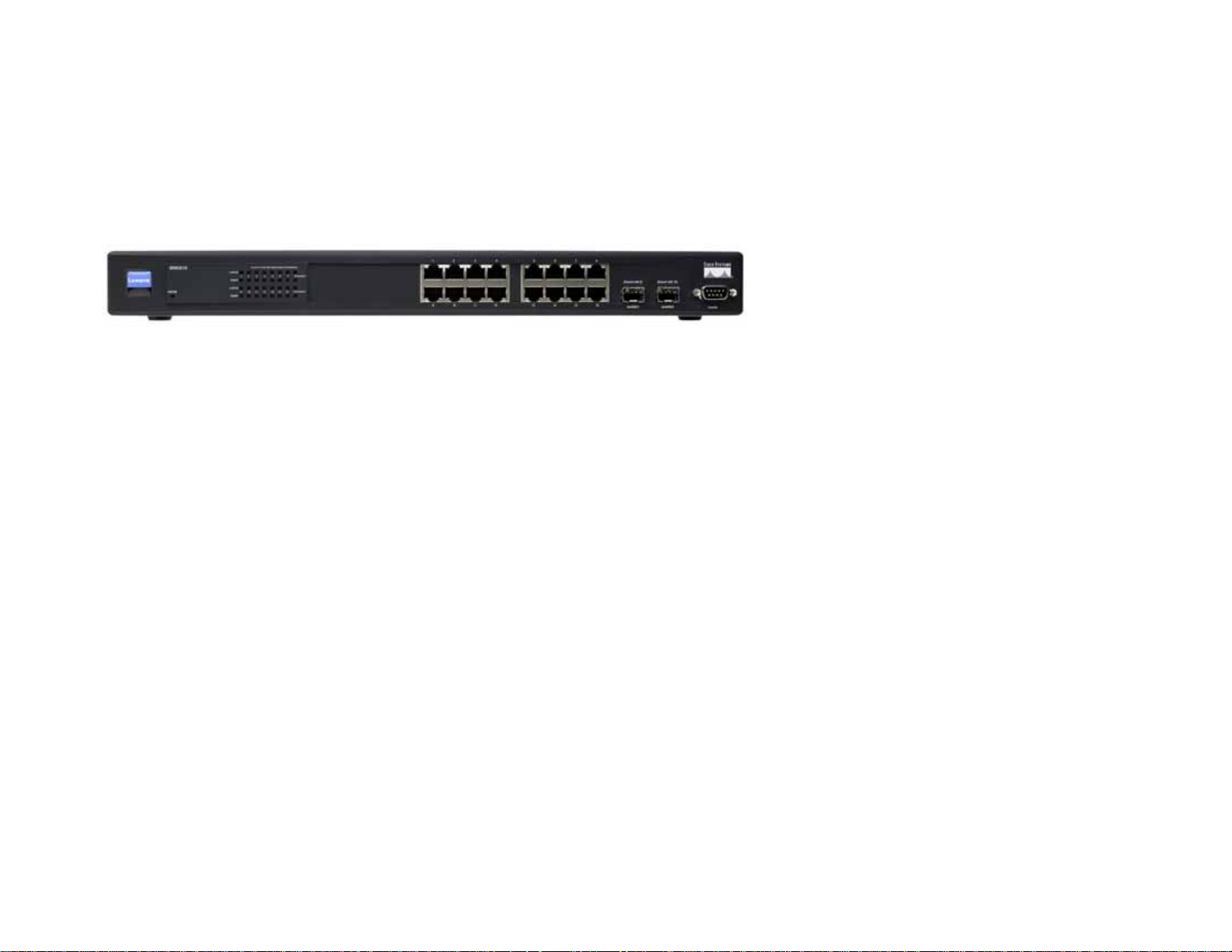
SRW2016
Front Panel
The Switch's LEDs and ports are located on the front panel.
Figure 2-5: Front Panel of the SRW2016
LEDs
SYSTEM Green. The SYSTEM LED lights up to indicate that the Switch is powered on.
Link/Act (1-16) Green. The LED lights up green to indicate a functional 10/100Mbps network link through
the corresponding port (1 through 16) with an attached device. It flashes to indicate that
the Switch is actively sending or receiving data over that port.
Gigabit (1-16) Orange. The LED lights up orange to indicate a 1000Mbps connection on the corresponding
port (1 through 16) with an attached device.
Ports
1-16 The Switch is equipped with 16 auto-sensing, Ethernet network ports, which use RJ-45
connectors. The Fast Ethernet ports support network speeds of 10Mbps, 100Mbps, or
1000Mbps. They can operate in half and full-duplex modes. Auto-sensing technology
enables each port to automatically detect the speed of the device connected to it (10Mbps,
100Mbps, or 1000Mbps), and adjust its speed and duplex accordingly.
Chapter 2: Getting to Know the Switch
SRW2016
8
Page 19
WebView Switches
miniGBIC 1-2 The miniGBIC (gigabit interface converter) port is a connection point for a miniGBIC
expansion module, so the Switch can be uplinked via fiber to another switc h. The MiniGBIC
port provides a link to a high-speed network segment or individual workstation at speeds
of up to 1000Mbps.
Use the Linksys MGBT1, MGBSX1, or MGBLH1 miniGBIC modules with the Switch. The
MGBSX1 and the MGBLH1 require fiber cabling with LC connectors, while the MGBT1
requires a Category 5e Ethernet cable with an RJ-45 connector.
Table 3: SRW2016 Shared Port Mapping
miniGBIC Port Standard Port
miniGBIC 1 Port 8
miniGBIC 2 Port 16
NOTE: On the SRW2016, MiniGBIC ports are shared
with standard ports. If a miniGBIC port is used, then
the shared standard port on the Switch cannot be
used. See "T able 1:SRW2016 Shared Port Mapping"
for port mapping details of the SRW2016 Switch.
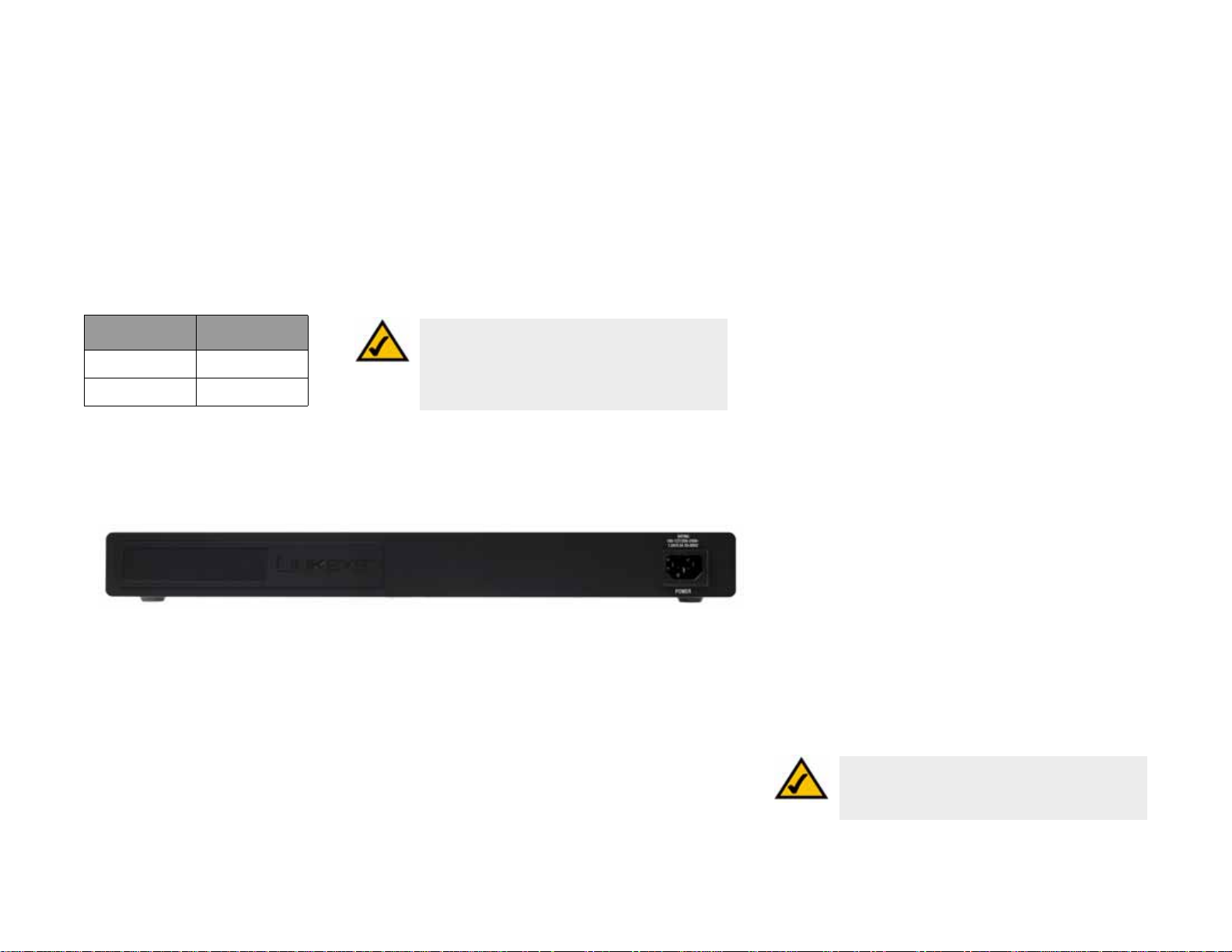
The Back Panel
The power port is located on the back panel of the Switch.
Figure 2-6: Back Panel of the SRW2016
Console The Console port is where you can connect a serial cable to a PC’s serial port for
configuration using your PC’s HyperTerminal program. Refer to Chapter 4: Using the
Console Interface for Configuration for more information.
Power The Power port is where you will connect the power cord.
NOTE: If you need to reset the Switch, unplug the
power cord from the back of the Switch. Wait a few
seconds and then reconnect it.
Chapter 2: Getting to Know the Switch
SRW2016
9
Page 20
WebView Switches
SRW248G4
Front Panel
The Switch's LEDs and ports are located on the front panel.
Figure 2-7: Front Panel of the SRW248G4
LEDs
PWR Green. The PWR LED lights up to indicate that the Switch is powered on.
Link/Act (1-48) Green. The LED lights up green to indicate a functional 10/100Mbps network link through
the corresponding port (1 through 48) with an attached device. It flashes to indicate that
the Switch is actively sending or receiving data over that port.
Link/Act (G1-G4) Green. The LED lights up green to indicate a functional 10/100Mbps network link through
the corresponding port (G1 through G4) with an attached device. It flashes to indicate that
the Switch is actively sending or receiving data over that port.
Orange. The LED lights up orange to indicate a 1000Mbps connection on the corresponding
port (G1 through G4) with an attached device. It flashes to indicate that the Switch is
actively sending or receiving data over that port.
Ports
1-48 The Switch is equipped with 48 auto-sensing Ethernet network ports, which use RJ-45
connectors. The Fast Ethernet ports support network speeds of 10Mbps or 100Mbps. They
can operate in half and full-duplex modes. Auto-sensing technology enables each port to
automatically detect the speed of the device connected to it (10Mbps or 100Mbps), and
adjust its speed and duplex accordingly.
Chapter 2: Getting to Know the Switch
SRW248G4
10
Page 21
WebView Switches
G1-G4 The Switch is equipped with 4 auto-sensing Gigabit Ethernet network ports, which use
RJ-45 connectors. The Gigabit Ethernet ports support network speeds of 10Mbps,
100Mbps, or 1000Mbps. They can operate in half and full-duplex modes. Auto-sensing
technology enables each port to automatically detect the speed of the device connected to
it (10Mbps, 100Mbps, or 1000Mbps), and adjust its speed and duplex accordingly.
miniGBIC 1-2 The miniGBIC (gigabit interface converter) port is a connection point for a miniGBIC
expansion module, so the Switch can be uplinked via fiber to another switc h. The MiniGBIC
port provides a link to a high-speed network segment or individual workstation at speeds
of up to 1000Mbps.
Use the Linksys MGBT1, MGBSX1, or MGBLH1 miniGBIC modules with the Switch. The
MGBSX1 and the MGBLH1 require fiber cabling with LC connectors, while the MGBT1
requires a Category 5e Ethernet cable with an RJ-45 connector.
Table 4: SRW248G4 Shared Port
Mapping
NOTE: On the SRW248G4, MiniGBIC ports are shared with
miniGBIC Port Gigabit Port
miniGBIC 1 Port G3
miniGBIC 2 Port G4
Gigabit Ethernet ports. If a miniGBIC port is used, then the
shared Gigabit Ethernet port on the Switch cannot be
used. See "Table 1:SRW248G4 Shared Port Mapping" for
port mapping details of the SRW248G4 Switch.
Back Panel
The power port is located on the back panel of the Switch.
Figure 2-8: Back Panel of the SRW248G4
Console The Console port is where you can connect a serial cable to a PC’s serial port for
configuration using your PC’s HyperTerminal program. Refer to Chapter 4: Using the
Console Interface for Configuration for more information.
Power The Power port is where you will connect the power cord.
Chapter 2: Getting to Know the Switch
SRW248G4
NOTE: If you need to reset the Switch, unplug the
power cord from the back of the Switch. Wait a few
seconds and then reconnect it.
11
Page 22

WebView Switches
SRW224G4
Front Panel
The Switch's LEDs and ports are located on the front panel.
Figure 2-9: Front Panel of the SRW224G4
LEDs
PWR Green. The PWR LED lights up to indicate that the Switch is powered on.
Link/Act (1-24) Green. The LED lights up green to indicate a functional 10/100Mbps network link through
the corresponding port (1 through 16) with an attached device. It flashes to indicate that
the Switch is actively sending or receiving data over that port.
Link/Act (G1-G4) Green. The LED lights up green to indicate a functional 10/100Mbps network link through
the corresponding port (G1 through G4) with an attached device. It flashes to indicate that
the Switch is actively sending or receiving data over that port.
1000Mbps (G1-G4) Orange. The LED lights up orange to indicate a 1000Mbps connection on the corresponding
port (G1 through G4) with an attached device.
Ports
1-24 The Switch is equipped with 24 auto-sensing, Ethernet network ports, which use RJ-45
connectors. The Fast Ethernet ports support network speeds of 10Mbps, 100Mbps, or
1000Mbps. They can operate in half and full-duplex modes. Auto-sensing technology
enables each port to automatically detect the speed of the device connected to it (10Mbps,
100Mbps, or 1000Mbps), and adjust its speed and duplex accordingly.
Chapter 2: Getting to Know the Switch
SRW224G4
12
Page 23
WebView Switches
G1-G4 The Switch is equipped with 4 auto-sensing Gigabit Ethernet network ports, which use RJ-
45 connectors. The Gigabit Ethernet ports support network speeds of 10Mbps, 100Mbps,
or 1000Mbps. They can operate in half and full-duplex modes. Auto-sensing technology
enables each port to automatically detect the speed of the device connected to it (10Mbps,
100Mbps, or 1000Mbps), and adjust its speed and duplex accordingly.
miniGBIC 1-2 The miniGBIC (gigabit interface converter) port is a connection point for a miniGBIC
expansion module, so the Switch can be uplinked via fiber to another switc h. The MiniGBIC
port provides a link to a high-speed network segment or individual workstation at speeds
of up to 1000Mbps.
Use the Linksys MGBT1, MGBSX1, or MGBLH1 miniGBIC modules with the Switch. The
MGBSX1 and the MGBLH1 require fiber cabling with LC connectors, while the MGBT1
requires a Category 5e Ethernet cable with an RJ-45 connector.
Table 5: SRW224G4 Shared Port
Mapping
NOTE: On the SRW224G4, MiniGBIC ports are shared with
miniGBIC Port Gigabit Port
miniGBIC 1 Port G3
miniGBIC 2 Port G4
Gigabit Ethernet ports. If a miniGBIC port is used, then the
shared Gigabit Ethernet port on the Switch cannot be
used. See "Table 1:SRW224G4 Shared Port Mapping" for
port mapping details of the SRW224G4 Switch.
Back Panel
The power port is located on the back panel of the Switch.
Figure 2-10: Back Panel of the SRW224G4
Console The Console port is where you can connect a serial cable to a PC’s serial port for
configuration using your PC’s HyperTerminal program. Refer to Chapter 4: Using the
Console Interface for Configuration for more information.
Power The Power port is where you will connect the power cord.
Chapter 2: Getting to Know the Switch
SRW224G4
NOTE: If you need to reset the Switch, unplug the
power cord from the back of the Switch. Wait a few
seconds and then reconnect it.
13
Page 24
WebView Switches
Chapter 3: Connecting the Switch
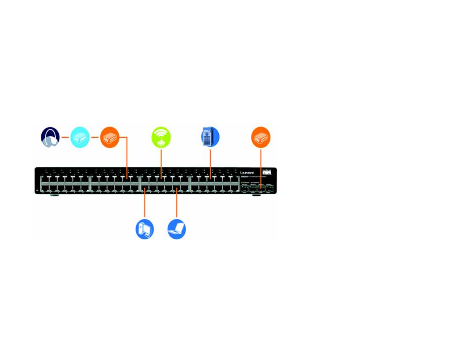
Overview
This chapter will explain how to connect network devices to the Switch. For an example of a typical network
configuration, see the application diagram shown below.
Internet
Cable/DSL
Modem
Wireless
Router
Figure 3-1: Typical Network Configuration for the SRW2048
Access Point
10/100/1000
Desktop
Server
10/100
Notebook
Uplink via Fiber
to Switch
Chapter 3: Connecting the Switch
Overview
14
Page 25

WebView Switches
When you connect your network devices, make sure you don’t exceed the maximum cabling distances, which are
listed in the following table:
Table 1: Maximum Cabling Distances
From To Maximum Distance
Switch Switch or Hub* 100 meters (328 feet)
Hub Hub 5 meters (16.4 feet)
Switch or Hub Computer 100 meters (328 feet)
*A hub refers to any type of 100Mbps hub, including regular hubs and stackable hubs. A 10Mbps hub connected
to another 10Mbps hub can span up to 100 meters (328 feet).
Before You Install the Switch...
When you choose a location for the Switch, observe the following guidelines:
• Make sure that the Switch will be accessible and that the cables can be easily connected.
• Keep cabling away from sources of electrical noise, power lines, and fluorescent lighting fixtures.
• Position the Switch away from water and moisture sources.
• To ensure adequate air flow around the Switch, be sure to provide a minimum clearance of two inches
(50 mm).
• Do not stack free-standing Switches more than four units high.
Chapter 3: Connecting the Switch
Before You Install the Switch...
15
Page 26
WebView Switches
Placement Options
Before connecting cables to the Switch, first you will physically install the Switch. Either set the Switch on its four
rubber feet for desktop placement or mount the Switch in a standard-sized, 19-inch wide, 1U high rack for rackmount placement.
Desktop Placement
1. Attach the rubber feet to the recessed areas on the bottom of the Switch.
2. Place the Switch on a desktop near an AC power source.
3. Keep enough ventilation space for the Switch and check the environmental restrictions mentioned in the
specifications.
4. Proceed to the section, “Connecting the Switch.”
Rack-Mount Placement
To mount the Switch in any standard-sized, 19-inch wide, 1U high rack, follow these instructions:
1. Place the Switch on a hard flat surface with the front panel facing you.
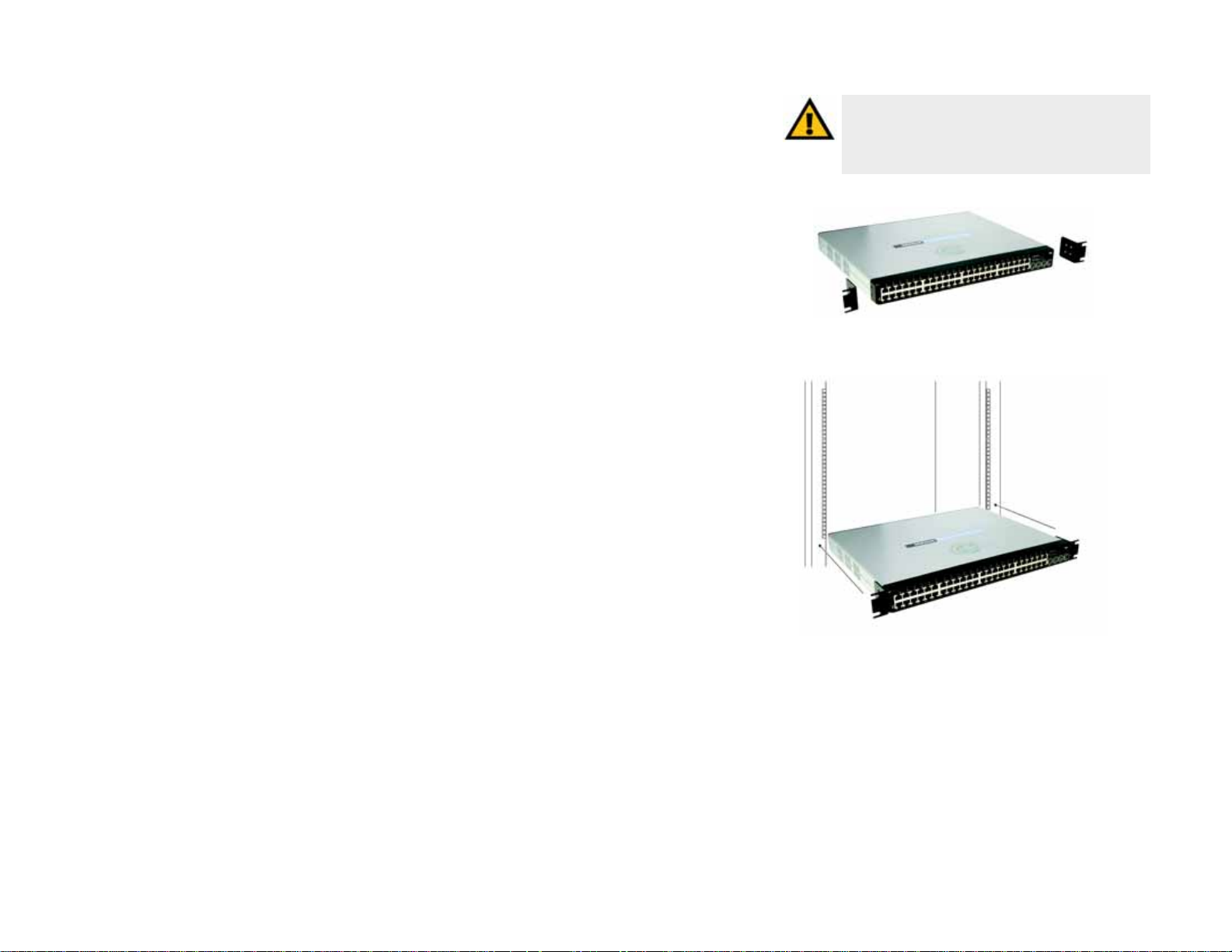
2. Attach a rack–mount bracket to one side of the Switch with the supplied screws. Then attach the other
bracket to the other side.
IMPORTANT: Make sure you use the screws
supplied with the mounting brackets. Using the
wrong screws could damage the Switch and would
invalidate your warranty.
Figure 3-2: Attach the Brackets to the Switch
3. Make sure the brackets are properly attached to the Switch.
4. Use the appropriate screws (not included) to securely attach the brackets to your rack.
Proceed to the section, “Connecting the Switch.”
Chapter 3: Connecting the Switch
Placement Options
Figure 3-3: Mount the Switch in the Rack
16
Page 27
WebView Switches
Connecting the Switch
To connect network devices to the Switch, follow these instructions:
1. Make sure all the devices you will connect to the Switch are powered off.
2. For 10/100Mbps devices, connect a Category 5 Ethernet network cable to one of the numbered ports on the
Switch. For a 1000Mbps device, connect a Category 5e Ethernet network cable to one of the numbered ports
on the Switch.
3. Connect the other end to a PC or other network device.
4. Repeat steps 2 and 3 to connect additional devices.
5. If you are using the miniGBIC port, then connect the miniGBIC module to the miniGBIC port. For detailed
instructions, refer to the module’s documentation.
6. If you will use the Switch’s console interface to configure the Switch, then connect the supplied serial cable
to the Switch’s Console port, and tighten the captive retaining screws. Connect the other end to your PC’s
serial port. (This PC must be running the VT100 terminal emulation software, such as HyperTerminal.)
7. Connect the supplied power cord to the Switch’s power port, and plug the other end into an electrical outlet.
IMPORTANT: Make sure you use the power cord that is supplied with the Switch. Use of a
different power cord could damage the Switch.
8. Power on the network devices connected to the Switch. Each active port’s corresponding Link/Act LED will
light up on the Switch. If a port has an active Gigabit connection, then its corresponding Gigabit LED will also
light up.
If you will use the Switch’s console interface to configure the Switch, proceed to Chapter 4: Using the
Console Interface for Configuration for directions.
If you will use the Switch’s Web-based Utility to configure the Switch, proceed to Chapter 5: Using the
Web-based Utility for Configuration.
Chapter 3: Connecting the Switch
Connecting the Switch
NOTE: If you need to reset the Switch, unplug the
power cord from the back of the Switch. Wait a
few seconds and then reconnect it.
17
Page 28
WebView Switches
Chapter 4: Using the Console Interface for Configuration
Overview
The Switch features a menu-driven console interface for basic configuration of the Switch and management of
your network. The Switch can be configured using CLI through the console interface or through a telnet
connection. This chapter describes console interface configuration. Configuration can also be performed through
the web utility, which is covered in the next chapter.
Configuring the HyperTerminal Application
Before you use the console interface, you will need to configure the HyperTerminal application on your PC.
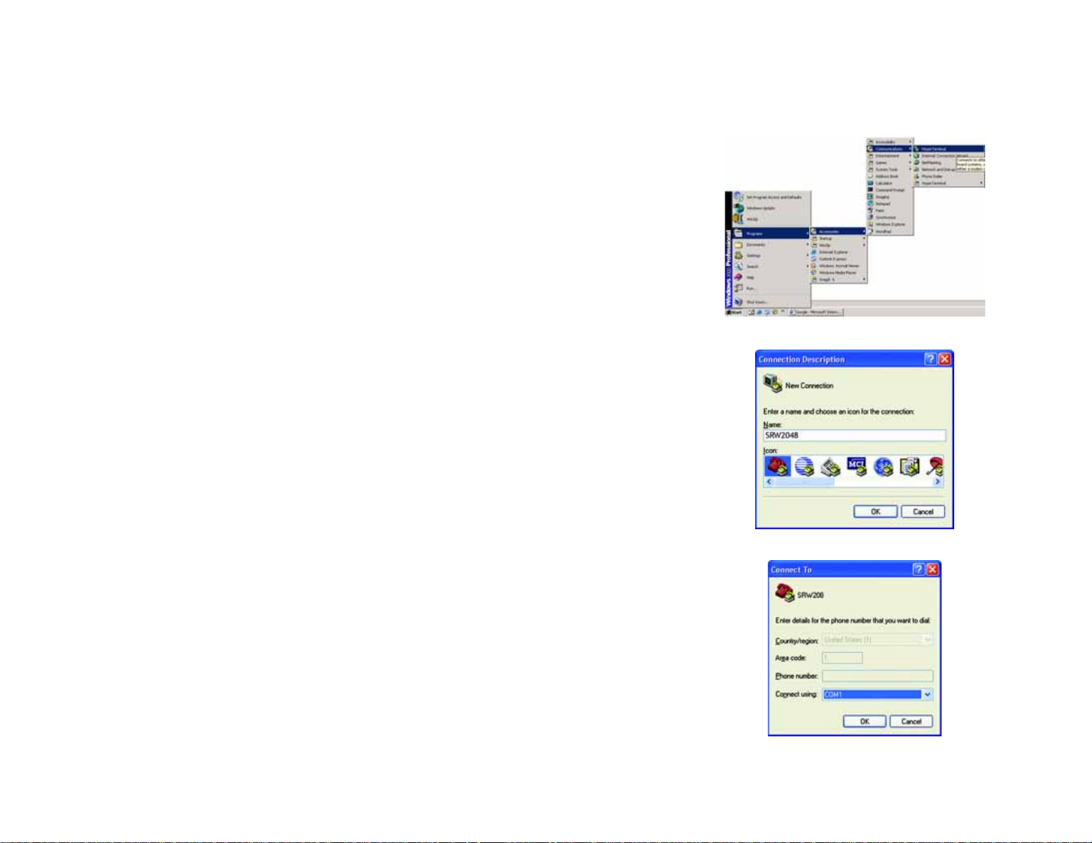
1. Click the Start button. Select Programs and choose Accessories. Select Communications. Select
HyperTerminal from the options listed in this menu.
2. On the Connection Description screen, enter a name for this connection. In the example, the name of
connection is SRW2048. Select an icon for the application. Then, click the OK button.
3. On the Connect To screen, select a port to communicate with the Switch: COM1, COM2, or TCP/IP.
Figure 4-1: Finding HyperTerminal
Chapter 4: Using the Console Interface for Configuration
Overview
Figure 4-2: Connection Description
Figure 4-3: Connect To
18
Page 29

WebView Switches
4. Set the serial port settings as follows:
Bits per second: 38400
Data bits: 8
Parity: None
Stop bits: 1
Flow control: None
Then, click the OK button.
Connecting to the Switch through a Telnet Session
Open a command line editor and enter telnet 192.168.1.254. Then, press the Enter key.
Figure 4-4: COM1 Properties
The Login screen will now appear. The first time you open the CLI interface, select Edit and hit Enter. Enter admin
in the User Name field. Leave the Password field blank.
Press the Esc button and you will return to the login screen. Use the right arrow button to navigate to Execute
and press the Enter button to enter the CLI interface.
Chapter 4: Using the Console Interface for Configuration
Connecting to the Switch through a Telnet Session
Figure 4-5: Telnet Login screen
19
Page 30

WebView Switches
Configuring the Switch through the Console Interface
The console screens consist of a series of menus. Each menu has several options, which are listed vertically. You
select a menu option when you highlight it; pressing the Enter key activates the highlighted option.
T o navigate through the menus and actions of the console interface, use the up or down arrow keys to move up or
down, and use the left or right arrow keys to move left or right. Use the Enter key to select a menu option, and use
the Esc key to return to the previous selection. Menu options and any values entered or present will be
highlighted. The bottom of the screen lists the actions available.
Switch Main Menu
The System Main Menu screen displays these choices:
1. System Configuration Information Menu
2. Port Status
3. Port Configuration
4. Help
0. Logout
Chapter 4: Using the Console Interface for Configuration
Configuring the Switch through the Console Interface
Figure 4-6: Switch Main Menu
20
Page 31

WebView Switches
System Configuration Menu
On the System Configuration Menu screen, you have these choices:
1. System Information
2. Management Settings
3. User & Password Settings
4. Security Settings
5. IP Configuration
6. File Management
7. Restore System Default Settings
8. Reboot System
0. Back to main menu
Figure 4-7: System Configuration Menu
Chapter 4: Using the Console Interface for Configuration
Configuring the Switch through the Console Interface
21
Page 32

WebView Switches
System Information
Using this screen, you can check the Switch’s firmware versions and general system information.
Versions
The Versions screen displays the Switch’s boot, software, and hardware firmware versions.
Figure 4-8: System Information Menu
General System Information
The General System Information screen displays the Switch’s description, System Up Time, System MAC
Address, System Contact, System Name, and System Location.
Select Edit and press the Enter key to make changes. When your changes are complete, press the Esc key to
return to the Action menu. Select Save and press the Enter key to save your changes. To exit, select Quit and
press the Enter key.
Chapter 4: Using the Console Interface for Configuration
Configuring the Switch through the Console Interface
Figure 4-9: Versions
Figure 4-10: General System Information
22
Page 33

WebView Switches
Management Settings
From the Management Settings screen, you can set Serial Port Session Configuration, Telnet Session
Configuration, or Secure Telnet (SSH) Configuration.
Serial Port Configuration
On the Serial Port Configuration screen, the Switch’s baud rate is displayed.
Select Edit and press the Enter key to make changes. Toggle to the desired speed and when your changes are
complete, press the Esc key to return to the Action menu. Select Save and press the Enter key to save your
changes. To exit, select Quit and press the Enter key.
Figure 4-11: Management Settings Menu
Telnet Configuration
On the Telnet Configuration screen, the time-out is displayed. The v alue is entered in seconds. If you do not w ant
the Telnet session to timeout, you may enter a value of 0 sec.
Select Edit and press the Enter key to make changes. When your changes are complete, press the Esc key to
return to the Action menu. Select Save and press the Enter key to save your changes. To exit, select Quit and
press the Enter key.
Chapter 4: Using the Console Interface for Configuration
Configuring the Switch through the Console Interface
Figure 4-12: Serial Port Configuration
Figure 4-13: Telnet Configuration
23
Page 34

WebView Switches
SSH Configuration
On the SSH Configuration screen, you can select SSH Server Configuration, SSH Server Status, SSH Crypto Key
Generation, and SSH Keys Fingerprints.
SSH Server Configuration
On the SSH Server Configuration screen, the SSH Server can be enabled or disabled by navigating to the SSH
Server option and using the SPACE bar to toggle the option. The SSH Server Port can be modified by entering in
the value.
Select Edit and press the Enter key to make changes. When your changes are complete, press the Esc key to
return to the Action menu. Select Save and press the Enter key to save your changes. To exit, select Quit and
press the Enter key.
SSH Status
The SSH Status screen displays whether the SSH Server is enabled, the RSA and DSA key status, and any open
SSH sessions.
Select Refresh to update the screen if necessary. To exit, select Quit and press the Enter key.
Figure 4-14: SSH Configuration
Figure 4-15: SSH Server Configuration
Chapter 4: Using the Console Interface for Configuration
Configuring the Switch through the Console Interface
Figure 4-16: SSH Status
24
Page 35

WebView Switches
SSH Crypto Key Generation
On the SSH Crypto Key Generation screen, the SSH Public Key Algorithm can be toggled between RSA and DSA
using the SPACE bar to toggle the option. The SSH Public Key Length cannot be modified.
Select Edit and press the Enter key to make changes. When your changes are complete, press the Esc key to
return to the Action menu. Select Save and press the Enter key to save your changes. To exit, select Quit and
press the Enter key.
SSH Keys Fingerprints
On the SSH Keys Fingerprints screen, the RSA and DSA keys will be displayed if they have been generated.
Select Refresh to update the screen if necessary. To exit, select Quit and press the Enter key.
Figure 4-17: SSH Crypto Key Generation
Chapter 4: Using the Console Interface for Configuration
Configuring the Switch through the Console Interface
Figure 4-18: SSH Keys Fingerprints
25
Page 36

WebView Switches
Username & Password Settings
From this screen, you can administer the user names and passwords of those accessing the Switch.
Select Edit and press the Enter key to make changes. When your changes are complete, press the Esc key to
return to the Action menu. Select Save and press the Enter key to save your changes. To exit, select Quit and
press the Enter key.
NOTE: The Username & Password Settings screen can also
be used to set passwords for other users.
Security Settings
The Security Settings screen enables you to configure security settings on the Switch, as well as generate and
display the certificate.
SSL Certificate Generation
Use the Certificate Generation screen to specify a device-generated certificate.
Figure 4-19: Username & Password Settings
The following fields are specified:
Public Key Length - Specifies the SSL RSA key length. (Range: 512 - 2048)
Organization Name - Specifies the organization name. (Range: 1 - 64)
Locality or City Name - Specifies the location or city name. (Range: 1 - 64)
State or Province Name - Specifies the state or province name. (Range: 1 - 64)
Country Name - Specifies the country name. (Range: 2 - 2)
Validity Term - Specifies number of days certification is valid. (Range: 30 - 3650)
Chapter 4: Using the Console Interface for Configuration
Configuring the Switch through the Console Interface
Figure 4-20: Security S ettings
Figure 4-21: SSL Certificate Generation
26
Page 37

WebView Switches
Show Certificate
Use the Show Certificate screen to display the internal certificate.
Disable Active Management Profile
Selecting this option will prompt you to confirm that you want to disable the Active Management Profile.
NOTE: This setting has no effect when Management Access
Rules are not defined.
Figure 4-22: SSL Certificate
IP Configuration
The IP Configuration screen displays these choices: the Switch’s IP Addr ess Settings, HTTP, HTTPS Configuration
and Network Configuration.
Chapter 4: Using the Console Interface for Configuration
Configuring the Switch through the Console Interface
Figure 4-23: IP Configuration
27
Page 38

WebView Switches
IP Address Configuration
The Switch’s IP information is displayed here.
IP Address. The IP Address of the Switch is displayed. (The default IP address is 192.168.1.254.) Verify that the
address you enter is correct and does not conflict with another device on the network.
Subnet Mask. The subnet mask of the Switch is displayed.
Default Gateway. The IP address of your network’s default gateway is displayed.
Management VLAN. The VLAN ID number is displayed.
DHCP client. The status of the DHCP client is displayed. If you want the Switch to be a DHCP client, then select
ENABLE. If you want to assign an static IP address to the Switch, then enter the IP settings and select DISABLE.
Select Edit to make changes. When your changes are complete, press the Esc key to return to the Action menu,
and select Save to save your changes.
HTTP
The HTTP screen displays the status and port number of the HTTP Server.
Select Edit and press the Enter key to make changes. When your changes are complete, press the Esc key to
return to the Action menu. Select Save and press the Enter key to save your changes. To exit, select Quit and
press the Enter key.
HTTPS Configuration
Use the HTTPS Configuration screen to configure HTTPS settings. You can enable or disable the HTTPS server
and configure the port on which the session is enabled.
Select Edit and press the Enter key to make changes. When your changes are complete, press the Esc key to
return to the Action menu. Select Save and press the Enter key to save your changes. To exit, select Quit and
press the Enter key.
Figure 4-24: IP Address Configuration
Figure 4-25: HTTP
Chapter 4: Using the Console Interface for Configuration
Configuring the Switch through the Console Interface
Figure 4-26: HTTPS Configuration
28
Page 39

WebView Switches
Network Configuration
The Network Configuration screen offers a choice of two tests, Ping and TraceRoute.
Ping
The Ping screen displays the IP address of the location you want to contact.
Select Edit to change the IP address, and select Execute to begin the ping test.
After the ping test is complete, the Ping screen displays the IP address, status, and statistics of the ping test.
Select Edit and press the Enter key to make changes. When your changes are complete, press the Esc key to
return to the Action menu. Select Save and press the Enter key to save your changes. To exit, select Quit and
press the Enter key.
Figure 4-27: Network Configuration
TraceRoute
The TraceRoute screen displays the IP address of the address whose route you want to trace.
Select Edit to change the IP address, and select Execute to begin the traceroute test.
After the traceroute test is complete, the TraceRoute screen displays the IP address, status, and statistics of the
traceroute test.
Select Edit and press the Enter key to make changes. When your changes are complete, press the Esc key to
return to the Action menu. Select Save and press the Enter key to save your changes. To exit, select Quit and
press the Enter key.
Chapter 4: Using the Console Interface for Configuration
Configuring the Switch through the Console Interface
Figure 4-28: Ping Test
Figure 4-29: TraceRoute Test
29
Page 40

WebView Switches
File Management
The File Management screen allows you to upload or download files, such as the startup configuration, boot, or
image file, using a TFTP server.
Select Edit to change the settings. When your changes are complete, press the Esc key to return to the Action
menu, and select Execute to upload or download the designated file.
If you are downloading a new boot & image, please follow these steps:
1. Download the new boot code. DO NOT RESET THE DEVICE!
2. Download the new software image.
3. Reset the device now.
NOTE: When downloading a configuration file, be sure that it is a valid configuration file.
If you have edited the file, ensure that only valid entries have been configured.
Restore System Default Settings
To restore the Switch back to the factory default settings, select Restore System Default Settings and press
the Enter key. You will be asked if you want to continue. Press the y key to restore the Switch’s default settings,
or press the n key to cancel.
Figure 4-30: File Management
Reboot System
Select Reboot System and press the Enter key if you want to restart the Switch. You will be asked if you want to
continue. Press the y key to reboot the Switch, or press the n key to cancel. After the Switch has rebooted, the
Switch Main Menu screen will appear.
Back to main menu
Select Back to main menu and press the Enter key if you want to return to the Switch Main Menu screen.
Chapter 4: Using the Console Interface for Configuration
Configuring the Switch through the Console Interface
Figure 4-31: Restore System Default Settings
Figure 4-32: Reboot System
30
Page 41

WebView Switches
Port Status
On the Switch Main Menu screen, select Port Status and press the Enter key if you want to view the status
information for the Switch’s ports.
The Port Status screen displays the port numbers, their status, Link status, speed and duplex mode, and status of
flow control, which is the flow of packet transmissions.
If you want to change any settings for a port, you must use the Port Configuration screen.
Port Configuration
On the Switch Main Menu screen, select Port Configuration and press the Enter key if you want to configure
the Switch’s ports.
The Port Configuration screen displays the port numbers, their status, auto-negotiation status, speed and duplex
mode, and status of flow control, which is the flow of packet transmissions.
Select Edit and press the Enter key to make changes. When your changes are complete, press the Esc key to
return to the Action menu. Select Save and press the Enter key to save your changes. To exit, select Quit and
press the Enter key.
Figure 4-33: P ort Status
Help
Select Help and press the Enter key if you want to view the help information. This screen explains how to
navigate the various screens of the console interface.
Chapter 4: Using the Console Interface for Configuration
Configuring the Switch through the Console Interface
Figure 4-34: Port Configuration
31
Page 42

WebView Switches
Chapter 5: Using the Web-based Utility for Configuration
Overview
This chapter describes the features included in the Web-based Utility. All of the features shown in this chapter,
unless specifically identified, are included in the all of WebView Switches. The screen images were taken from
the SRW2048 Switch. Additional features for specific Switches are noted. Some functionality on the SRW224G4,
SRW248G4, SRW2016 and SRW2024 Switches may not be fully functional but will be corrected with future
firmware upgrades.
Accessing the Web-based Utility
NOTE: The Web-based Utility is optimized for viewing with a screen resolution of 1024 x 768.
Internet Explorer version 5.5 or above is recommended.
Open your web browser and enter 192.168.1.254 into the Address field. Press the Enter key and the login
screen will appear.
NOTE: The default IP address of the device is 192.168.1.254. If you have modified this address,
enter the correct IP address. The device should be on the same subnet as the management station
used to configure the device.
The first time you open the Web-based Utility, enter admin in the User Name field, and leave the Password field
blank. Click the OK button. For security purposes, it is recommended that later you set a password from the
System Password screen.
Figure 5-1: Login Screen
The first screen that appears is the Setup Summary screen. Twelve main tabs are accessible from the Webbased Utility: Setup, Port Management, VLAN Management, Statistics, ACL, Security, QoS (Quality of Service),
Spanning Tree, Multicast, SNMP, Admin, and Logout. Click one of the main tabs to view additional tabs.
The LEDs on the Setup Summary screen display status information about their corresponding ports. A green LED
indicates a connection, while a grey LED indicates no connection. An orange LED indicates the port has been
closed down by the administrator. When you click a port’s LED, the statistics for that port are displayed.
NOTE: The LEDs displayed in the Web-based Utility are not the same as the LEDs on the front panel
of the Switch. The front panel LEDs display different status information, which is described in
Chapter 2: Getting to Know the Switch.
Chapter 5: Using the Web-based Utility for Configuration
Overview
NOTE: After configuring values using the Web-based
Utility, you may be required to refresh the page to see
the updated configuration.
32
Page 43

WebView Switches
Setup Tab - Summary
The Summary screen provides device and system information about the Switch.
Device Information
System Name. Displays the name for the Switch, if one has been entered on the Setup - Network Settings tab.
IP Address.The IP address of the Switch is displayed here (configurable from Setup - Network Settings tab).
Subnet Mask. The Subnet Mask of the Switch is displayed here (configurable from Setup - Network Settings
tab).
DNS Servers.The DNS Servers are displayed here (configurable from Setup - Network Settings tab).
Default Gateway. The Default Gateway is displayed here (configurable from Setup - Network Settings tab).
Address Mode. Indicates whether the Switch is configured with a Static or Dynamic IP address (configurable
from Setup - Network Settings tab).
Base MAC Address. This is the MAC address of the Switch.
System Information
Serial Number. The product’s Serial Number is displayed here.
Model Name. This is the model number and name of the Switch.
Hardw are Version. The version number of the Switch’s hardware is displayed here.
Boot Version. Indicates the system boot version currently running on the device.
Firmware Version. The Firmware (software) version number is displayed here.
System Location. The system name is displayed here (configurable from Setup - Network Settings tab).
System Contact. The contact person for this Switch is displayed here (configurable from Setup - Network
Settings tab).
System Up Time. This displays the amount of time that has elapsed since the Switch was last reset.
Current Time. The system time is displayed here (configurable from Setup - Time tab).
Figure 5-2: Setup - Summary
Chapter 5: Using the Web-based Utility for Configuration
Setup Tab - Summary
33
Page 44

WebView Switches
Setup Tab - Network Settings
The Network Settings screen allows you to assign DHCP or static IP settings to interfaces and assign default
gateways.
Identification
System Name. This field allows you to assign a system name.
System Location. This field is used for entering a description of where the Switch is located, such as 3rd floor.
System Contact. Enter the administrative contact person in this field.
System Object ID. The system object identifier is displayed here.
Base MAC Address. This is the MAC address of the Switch.
IP Configuration
Management VLAN. This drop-down allows you to select the Management VLAN.
IP Address Mode. This drop-down allows you to select Static or Dynamic IP address configuration.
Host Name. Enter the DHCP Host Name here.
Figure 5-3: Setup - Network Settings
IP Address. If using a static IP address, enter the IP address here.
Subnet Mask. If using a static IP address, enter the subnet mask of the currently configured IP address.
Default Gateway. If using a static IP address, enter the IP address of the Default Gateway.
DNS Server. Enter the primary DNS Server information.
Click the Save Settings button to save your changes or click Cancel Changes to discard the information.
Chapter 5: Using the Web-based Utility for Configuration
Setup Tab - Network Settings
34
Page 45

WebView Switches
Setup Tab - Time
The Time screen allows you to configure the time settings for the Switch.
Set Time
Use System Time. When this option is selected, the local hardware clock is utilized.
Use SNTP Time. When this option is selected, the time is synchronized to an SNTP (Simple Network Time
Protocol) server.
Local Time
Hours. The hour can be entered here.
Minutes. The minutes can be entered here.
Seconds. The seconds can be entered here.
Month. The month can be entered here.
Day. The da y ca n be entered here.
Year. The year can be entered here.
Time Z one. Enter the difference between Greenwich Mean Time (GMT) and local time.
Daylight Saving
Daylight Saving. Select Daylight Saving to enable it on the Switch. If the Switch should use US daylight
savings, then select USA. If the Switch should use EU daylight savings, then select European. If it should use
another kind of daylight savings, then select Custom and complete the From and To fields.
Time Set Offset (1-1440). For non-US and European countries, specify the amount of time for daylight savings.
The default is 60 minutes.
From. If you selected Other for the Daylight Saving setting, then enter the date and time when daylight savings
begins.
To. If you selected Other for the Daylight Saving setting, then enter the date and time when daylight savings ends.
Figure 5-4: Setup - Time
Chapter 5: Using the Web-based Utility for Configuration
Setup Tab - Time
35
Page 46

WebView Switches
Recurring. If you selected Other for the Daylight Saving setting and daylight savings has the same start and end
dates and times every year, then select Recurring.
From. If you selected Recurring, then enter the date and time when daylight savings begins.
To. If you selected Recurring, then enter the date and time when daylight savings ends.
SNTP Servers
Server1. Enter the primary SNTP server here.
Server2. Enter a secondary SNTP server here.
SNTP Polling Interval (60-86400). The value defined here determines the amount of time (in seconds) before
the Switch polls the SNTP server. The default value is every 1024 seconds (approx. 17 minutes).
Click the Save Settings button to save your changes or click Cancel Changes to discard the information.
Port Management Tab - Port Settings
The Port Management - Port Settings screen shows you the settings for each of the Switch’s ports.
Port. The number of the port. To use an SFP module, click on the Detail button of the appropriate port (G1, G2).
Description. Displays a brief description of the port (can be entered by clicking on the Detail button).
Administrative Status. The port can be taken offline by selecting the Down option. When Up is selected, the port
can be accessed normally.
Link Status. Up indicates a port has an active connection, Down indicates there is no active connection or the
port has been taken offline by an Administrator.
Speed. The connection speed of the port is displayed here. The speed can be configured only when
auto-negotiation is disabled on that port.
Duplex. This is the port duplex mode, Full (transmission occurs in both directions simultaneously) or Half
(transmission occurs in only one direction at a time). This mode can be configured only when auto-negotiation is
disabled and port speed is set to 10Mbps or 100Mbps. It cannot be configured on Link Aggregation Groups
(LAGs).
Chapter 5: Using the Web-based Utility for Configuration
Port Management Tab - Port Settings
Figure 5-5: Port Management - Port Settings
36
Page 47

WebView Switches
MDI/MIDX. This is the MDI/MDIX status of the port. The MDI setting is used if the port is connected to an end
station. The MDIX setting is used if the port is connected to a hub or another switch.
Flow Control. This is the flow control status of the port. It is active when the port uses Full Duplex Mode.
Type. Displays the port type.
LAG. This indicates if the port is part of a LAG.
PVE. When a port is a Private VLAN Edge (PVE) port, it bypasses the Forwarding Database and forwards all
unicast, multicast, and broadcast traffic to an uplink. Uplinks can be ports or LAGs.
Detail. The Detail button will open the Port Configuration Detail screen.
Port Configuration Detail screen
Port. The number of the port.
Description. Displays a brief description of the port (can be entered by clicking on the Detail button).
Port Type. This is the port type.
Admin Status. The port can be taken offline by selecting the Down option. When Up is selected, the port can be
accessed normally.
Current Port Status. The current status of the port is displayed here.
Reactivate Suspended Port. If you want to reactivate a port that has been suspended, click the checkbox.
Operational Status. This indicates whether or not the port is active.
Admin Speed. Change the speed of the port here.
Current Port Speed. The current speed of the port is displayed here.
Admin Duplex. Change the duplex mode here.
Current Duplex Mode. This is the duplex mode of the port.
Auto Negotiation. You can enable or disable the port’s Auto Negotiation feature. If using an SFP module, Auto
Negotiation for the specific port should be set to Disable.
Current Auto Negotiation. This is the current setting of the port’s Auto Negotiation feature.
Chapter 5: Using the Web-based Utility for Configuration
Port Management Tab - Port Settings
Figure 5-6: Port Settings - Port Configuration Detail
37
Page 48

WebView Switches
Admin Advertisement. Specifies the capabilities to be advertised by the port. Multiple options may be selected
or Max Capability can be selected to cover all of the options. The available options are:
• Max Capability. Indicates that the port speeds and duplex mode settings can be accepted.
• 10 Half. Indicates that the port is advertising a 10Mbps half duplex mode setting.
• 10 Full. Indicates that the port is advertising a 10Mbps full duplex mode setting.
• 100 Half. Indicates that the port is advertising a 100Mbps half duplex mode setting.
• 100 Full. Indicates that the port is advertising a 100Mbps full duplex mode setting.
• 1000. Indicates that the port is advertising a 1000Mbps full duplex mode setting.
Current Advertisement. The port advertises its capabilities to its neighbor port to begin the negotiation process.
This field displays the current advertisement settings.
Neighbor Advertisement. The neighbor port (the port to which the selected interface is connected) advertises
its capabilities to the port to start the negotiation process. This field displays the neighbor’s current settings.
Back Pressure. The Back Pressure feature of the selected port can be enabled or disabled.
Current Back Pressure. Displays whether Back Pressure is enabled or disabled on the currently selected port.
Flow Control. The Flow Control feature of the selected port can be enabled or disabled.
Current Flow Control. Displays whether Flow Control is enabled or disabled on the currently selected port.
MDI/MDIX. Select the Auto setting if you want the port to automatically detect the cable type. Select MDI if the
port is connected to an end station. Select MDIX if the port is connected to a hub or another switch.
Current MDI/MDIX. This is the current MDI/MDIX status of the port.
PVE. When a port is a Private VLAN Edge (PVE) port, it bypasses the Forwarding Database and forwards all
unicast, multicast, and broadcast traffic to an uplink.
LAG. This will indicate if a port is part of a LAG.
NOTE: The SRW248G4 and SRW224G4 only offer the
1000 option on ports G1-G4.
NOTE: All ports in the same PVE group should join the
same VLAN group.
Click the Save Settings button to save your changes.
Chapter 5: Using the Web-based Utility for Configuration
Port Management Tab - Port Settings
38
Page 49

WebView Switches
Port Management Tab - Link Aggregation
LAG. This indicates if the port is part of a LAG.
Description. Description for this LAG.
Admin Status. The admin status of the LAG. Up indicates that the LAG is available. Down indicates that
administrator has taken the port offline. When modifying the option, be sure to click the Save Settings option.
Type. The type of LAG is displayed here.
Link Status. The link status is displayed here.
Speed. The connection speed is displayed here.
Duplex. The connection duplex is displayed here.
Flow Control. This is the flow control status of the LAG. It is active when the port uses Full Duplex Mode.
LAG Mode. Displays the LAG status, On, Off, or Not Present.
Detail button. The Detail button opens up the Link Aggregation Detail screen.
Link Aggregation Detail screen
Figure 5-7: Port Management - Link Aggregration
LAG Configuration
LAG. The number of the selected LAG.
Description. A general description can be listed here for reference.
LACP. Indicates if the LAG is in LACP (Link Aggregation Control Protocol) mode.
LAG Type. The port types that comprise the LAG.
Administrative Status. Enables or disables traffic forwarding through the selected LAG.
Current Status. Indicates if the LAG is currently operating.
Reactivate Suspended LAG. Reactivates a LAG if the LAG has been disabled as a result of a port lock or ACL
operation.
Chapter 5: Using the Web-based Utility for Configuration
Port Management Tab - Link Aggregation
Figure 5-8: Link Aggregation - Link Aggregation Detail
39
Page 50

WebView Switches
Operational Status. Displays the current status of the LAG.
Admin Auto Negotiation. Enables or disables Auto Negotiation on the LAG. Auto-negotiation is a protocol
between two link partners that enables a LAG to advertise its transmission rate, duplex mode and flow control
(the flow control default is disabled) abilities to its partner.
Current Auto Negotiation. The current Auto Negotiation setting.
Admin Speed. The configured speed at which the LAG is operating.
Current LAG Speed. The current speed at which the LAG is operating.
Admin Flow Control. Enables or disables flow control or enables the auto negotiation of flow control on the LAG.
Current Flow Control. The user-designated Flow Control setting.
PVE. Displays the PVE group to which the LAG is configured.
Select Ports
Ports. Displays the ports that are members of the selected LAG.
Port Management Tab - LACP
Aggregate ports can be linked into link-aggregation port groups. Each group is comprised of ports with the same
speed, set to full-duplex operation.
Aggregated Links can be manually setup or automatically established by enabling Link Aggregation Control
Protocol (LACP) on the relevant links. Aggregate ports can be linked into link-aggregation port-groups. Each
group is comprised of ports with the same speed. The LACP screen contains fields for configuring LACP LAGs.
LACP System Priority. Indicates the global LACP priority value . The possible range is 1- 65535. The default value
is 1.
Port. Defines the port number to which timeout and priority values are assigned.
LACP Port Priority. Defines the LACP priority value for the port. The field range is 1-65535.
LACP Timeout. Administrative LACP timeout. A short or long timeout value can be selected. Long is the default.
Admin Key. A channel will only be formed between ports having the same admin key. This only applies to ports
located on the same switch.
Chapter 5: Using the Web-based Utility for Configuration
Port Management Tab - LACP
Figure 5-9: Port Management - LACP
40
Page 51

WebView Switches
VLAN Management Tab - Create VLAN
The Create VLAN screen provides information and global parameters for configuring and working with VLANs.
Single VLAN
VLAN ID (2-4094). Indicates the ID number of the VLAN being configured. Up to 256 VLANs can be created. This
field is used to add VLANs one at a time. To add the defined VLAN ID number, press the Add button.
VLAN Name. Displays the user-defined VLAN name.
VLAN Range
VLAN Range. Indicates a range of VLANs being configured. To add the defined range of VLAN ID numbers, press
the Add Range button.
VLAN Table
The VLAN Table displays a list of all configured VLANs. The VLAN ID, VLAN Name, and status of the VLAN are
displayed here. To remove a VLAN, click the Remove button.
VLAN Management Tab - Port Setting
The VLAN Port Setting screen provides parameters for managing ports that are part of a VLAN. The port default
VLAN ID (PVID) is configured on the VLAN Port Setting screen. All untagged packets arriving to the device are
tagged by the ports PVID.
Port. The port number included in the VLAN.
Mode. Indicates the port mode. Possible values are:
• General. The port belongs to VLANs, and each VLAN is user-defined as tagged or untagged (full 802.1Q
mode).
• Access. The port belongs to a single untagged VLAN. When a port is in Access mode, the packet types
which are accepted on the port (packet type) cannot be designated. It is also not possible to enable/
disable ingress filtering on an access port.
• Trunk. The port belongs to VLANs in which all ports are tagged (except for an optional single native VLAN).
Figure 5-10: VLAN Management - Create VLAN
NOTE: VLANs that are created dynamically using
GVRP are assigned a VLAN name “Undefined”.
Figure 5-11: VLAN Management - Port Settings
Chapter 5: Using the Web-based Utility for Configuration
VLAN Management Tab - Create VLAN
41
Page 52

WebView Switches
Acceptable Frame Type. Packet type accepted on the port. Possible values are:
• Admit All. Indicates that both tagged and untagged packets are accepted on the port.
• Admit Tag Only. Indicates that only tagged packets are accepted on the port.
PVID. Assigns a VLAN ID to untagged packets. The possible values are 2 to 4094. VLAN 4095 is defined as per
standard and industry practice as the discard VLAN. Packets classified to the Discard VLAN are dropped.
Ingress Filtering. Enables or disables Ingress filtering on the port. Ingress filtering discards packets which do
not include an ingress port.
LAG. Indicates the LAG to which the VLAN is defined.
VLAN Management Tab - Ports to VLAN
The Ports to VLAN screen contains fields for configuring ports to a VLAN. The port default VLAN ID (PVID) is
configured on the Create VLAN screen. All untagged packets arriving to the device are tagged by the ports PVID.
The Ports to VLAN screen contains a Port Table for VLAN parameters for each ports. Ports are assigned VLAN
membership by selecting and configuring the presented configuration options.
VLAN. The VLAN number.
Access. Indicates the port belongs to a single untagged VLAN. When a port is in Access mode, the packet types
which are accepted on the port cannot be designated. Ingress filtering cannot be enabled/disabled on an access
port.
Trunk. Indicates the port belongs to VLANs in which all ports are tagged, except for one port that can be
untagged.
General. Indicates the port belongs to VLANs, and each VLAN is user-defined as tagged or untagged (full 802.1Q
mode).
Tagged. Defines the interface as a tagged member of a VLAN. All packets forwarded by the interface are tagged.
The packets contain VLAN information.
Untagged. Packets forwarded by the interface are untagged.
Forbidden. Forbidden ports are not included in the VLAN.
Chapter 5: Using the Web-based Utility for Configuration
VLAN Management Tab - Ports to VLAN
Figure 5-12: VLAN Management - Ports to VLAN
42
Page 53

WebView Switches
Exclude. Excludes the interface from the VLAN. However, the interface cannot be added to the VLAN through
GVRP.
VLAN Management Tab - VLAN to Ports
The VLAN to Ports screen contains fields for configuring VLANs to a ports.
Port. Displays the interface number.
Mode. Indicates the port to VLAN mode. The possible field values are:
• General. Indicates the port belongs to VLANs, and each VLAN is user-defined as tagged or untagged (full
802.1Q mode).
• Access. Indicates the port belongs to a single untagged VLAN. When a port is in Access mode, the packet
types which are accepted on the port cannot be designated. Ingress filtering cannot be enabled/disabled
on an access port.
• Trunk. Indicates the port belongs to VLANs in which all ports are tagged, except for one port that can be
untagged.
Join VLAN. Defines the VLANs to which the interface is joined.
Figure 5-13: VLAN Management - VLAN to Ports
VLANs. Displays the PVID tag.
LAG. Indicates if the port is a member of a LAG. If it is a member of a LAG, i t cannot be configur ed to a VLAN. The
LAG to which it belongs can be configured to a VLAN.
Chapter 5: Using the Web-based Utility for Configuration
VLAN Management Tab - VLAN to Ports
Figure 5-14: VLAN to Ports - Join VLAN
43
Page 54

WebView Switches
VLAN Management Tab - GVRP
GARP VLAN Registration Protocol (GVRP) is specifically provided for automatic distribution of VLAN membership
information among VLAN-aware bridges. GVRP allows VLAN-aware bridges to automatically learn VLANs to
bridge ports mapping, without having to individually configure each bridge and register VLAN membership.
The Global System LAG information displays the same field information as the ports, but represents the LAG GVRP
information.
The GVRP screen is divided into two areas, GVRP and GVRP Table. The field definitions for both areas are the
same.
Enable GVRP. Enables and disables GVRP on the device.
Interface. DIsplays the interface on which GVRP is enabled. The possible field values are:
• Port. Indicates the port number on which GVRP is enabled.
• LAG. Indicates the LAG number on which GVRP is enabled.
GVRP State. When the checkbox is checked, GVRP is enabled on the interface.
Dynamic VLAN Creation. When the checkbox is checked, Dynamic VLAN creation is enabled on the interface.
GVRP Registration. When the checkbox is checked, VLAN registration through GVRP is enabled on the device.
The Update button adds the configured GVRP setting to the table at the bottom of the screen.
Figure 5-15: VLAN Management - GVRP
Chapter 5: Using the Web-based Utility for Configuration
VLAN Management Tab - GVRP
44
Page 55

WebView Switches
Statistics Tab - RMON Statistics
The RMON Statistics screen contains fields for viewing information about device utilization and errors that
occurred on the device.
Interface. Indicates the device for which statistics are displayed. The possible field values are:
• Port. Defines the specific port for which RMON statistics are displayed.
• LAG. Defines the specific LAG for which RMON statistics are displayed.
Refresh Rate. Defines the amount of time that passes before the interface statistics are refreshed. The possible
field values are:
• No Refresh. Indicates that the RMON statistics are not refreshed.
• 15 Sec. Indicates that the RMON statistics are refreshed every 15 seconds.
• 30 Sec. Indicates that the RMON statistics are refreshed every 30 seconds.
• 60 Sec. Indicates that the RMON statistics are refreshed every 60 seconds.
Drop Events. Displays the number of dropped events that have occurred on the interface since the device was
last refreshed.
Received Bytes (Octets). Displays the number of octets received on the interface since the device was last
refreshed. This number includes bad packets and FCS octets, but excludes framing bits.
Received Packets. Displays the number of packets received on the interface, including bad packets, Multicast
and broadcast packets, since the device was last refreshed.
Broadcast Packets Received. Displays the number of good broadcast packets received on the interface since
the device was last refreshed. This number does not include Multicast packets.
Multicast Packets Received. Displays the number of good Multicast packets received on the interface since the
device was last refreshed.
CRC & Align Errors. Displays the number of CRC and Align errors that have occurred on the interface since the
device was last refreshed.
Figure 5-16: Statistics - RMON Statistics
Undersize Packets. Displays the number of undersized packets (less than 64 octets) received on the interface
since the device was last refreshed.
Chapter 5: Using the Web-based Utility for Configuration
Statistics Tab - RMON Statistics
45
Page 56

WebView Switches
Oversize Packets. Displays the number of oversized packets (over 1518 octets) received on the interface since
the device was last refreshed.
Fragments. Displays the number of fragments (packets with less than 64 octets, excluding framing bits, but
including FCS octets) received on the interface since the device was last refreshed.
Jabbers. Displays the total number of received packets that were longer than 1518 octets. This number excludes
frame bits, but includes FCS octets that had either a bad Frame Check Sequence (FCS) with an integral number of
octets (FCS Error) or a bad FCS with a non-integral octet (Alignment Error) number. The field range to detect
jabbers is between 20 ms and 150 ms.
Collisions. Displays the number of collisions received on the interface since the device was last refreshed.
Frames of xx Bytes. Number of xx-byte frames received on the interface since the device was last refreshed.
Clear Counters button. This option will reset all of the statistic counts.
Refresh Now button. Use this option to refresh the statistics that are displayed on the page.
Statistics Tab - RMON History
The RMON History screen contains information about samples of data taken from ports. For example, the samples
may include interface definitions or polling periods.
The RMON History Control screen is divided into RMON History and Log Table.
Source Interface. Displays the interface from which the history samples were taken. The possible field values
are:
• Port. Specifies the port from which the RMON information was taken.
• LAG. Specifies the port from which the RMON information was taken.
Sampling Interval. Indicates (in seconds) the time that samplings are taken from the ports. The field range is 1-
3600. The default is 1800 seconds (equal to 30 minutes).
Max No. of Samples to Keep. Indicates the number of samples to save.
Owner. Displays the RMON station or user that requested the RMON information. The field range is 0-20
characters
The Add to List button adds the configured RMON sampling to the Log Table at the bottom of the screen.
Chapter 5: Using the Web-based Utility for Configuration
Statistics Tab - RMON History
Figure 5-17: Statistics - RMON History
46
Page 57

WebView Switches
Log Table
Source Interface. Displays the interface from which the history samples were taken.
Sampling Interval. Indicates the time in seconds that samplings are taken from the port.
Sampling Requested. Displays the number of samples to be saved. The field range is 1-65535. The default value
is 50.
Current Number of Samples. Displays the current number of samples taken.
View History Table button. This button opens the RMON History screen.
RMON History
The RMON History screen contains interface specific statistical network samplings. Each table entry represents
all counter values compiled during a single sample.
History Entry No. Displays the history table entry number.
Owner. Displays the RMON station or user that requested the RMON information. The field range is 0-20
characters.
Sample No. Indicates the sample number from which the statistics were taken.
Drop Events. Displays the number of dropped events that have occurred on the interface since the device was
last refreshed. This option is not available on the SRW224G4 and SRW248G4.
Received Bytes (Octets). Displays the number of octets received on the interface since the device was last
refreshed. This number includes bad packets and FCS octets, but excludes framing bits.
Received Packets. Displays the number of packets received on the interface since the device was last
refreshed, including bad packets, Multicast and Broadcast packets.
Broadcast Packets. Displays the number of good Broadcast packets received on the interface since the device
was last refreshed. This number does not include Multicast packets.
Multicast Packets. Displays the number of good Multicast packets received on the interface since the device
was last refreshed.
CRC Align Errors. Displays the number of CRC and Align errors that have occurred on the interface since the
device was last refreshed.
Chapter 5: Using the Web-based Utility for Configuration
Statistics Tab - RMON History
Figure 5-18: RMON History Table
47
Page 58

WebView Switches
Undersize Packets. Displays the number of undersized packets (less than 64 octets) received on the interface
since the device was last refreshed.
Oversize Packets. Displays the number of oversized packets (over 1518 octets) received on the interface since
the device was last refreshed.
Fragments. Displays the number of fragments (packets with less than 64 octets, excluding framing bits, but
including FCS octets) received on the interface since the device was last refreshed.
Jabbers. Displays the total number of received packets that were longer than 1518 octets. This number excludes
frame bits, but includes FCS octets that had either a bad Frame Check Sequence (FCS) with an integral number of
octets (FCS Error) or a bad FCS with a non-integral octet (Alignment Error) number. The field range to detect
jabbers is between 20 ms and 150 ms.
Collisions. Displays the number of collisions received on the interface since the device was last refreshed.
Utilization. Displays the percentage of the interface utilized.
Statistics Tab - RMON Alarm
The RMON Alarm screen contains fields for setting network alarms. Network alarms occur when a network
problem, or event, is detected. Rising and falling thresholds generate events.
Alarm Entry. Indicates a specific alarm.
Source Interface. Displays the interface for which RMON statistics are displayed. The possible field values are:
• Port. Displays the RMON statistics for the selected port.
• LAG. Displays the RMON statistics for the selected LAG.
Counter Name. Displays the selected MIB variable.
Sample Type. Defines the sampling method for the selected variable and comparing the value against the
thresholds. The possible field values are:
• Absolute. Compares the values directly with the thresholds at the end of the sampling interval.
• Delta. Subtracts the last sampled value from the current value. The difference in the values is compared
to the threshold.
Chapter 5: Using the Web-based Utility for Configuration
Statistics Tab - RMON Alarm
Figure 5-19: Statistics - RMON Alarm
48
Page 59

WebView Switches
Rising Threshold. Displays the rising counter value that triggers the rising threshold alarm. The rising threshold
is presented on top of the graph bars. Each monitored variable is designated a color.
Rising Event. Displays the mechanism in which the alarms are reported. The possible field values are:
• LOG. Indicates there is not a saving mechanism for either the device or in the management system. If the
device is not reset, the entry remains in the Log Table.
• TRAP. Indicates that an SNMP trap is generated, and sent via the Trap mechanism. The Trap can also be
saved using the Trap mechanism.
• Both. Indicates that both the Log and Trap mechanism are used to report alarms.
Falling Threshold. Displays the falling counter value that triggers the falling threshold alarm. The falling
threshold is graphically presented on top of the graph bars. Each monitored variable is designated a color.
Falling Event. Displays the mechanism in which the alarms are reported. The possible field values are:
• LOG. Indicates there is not a saving mechanism for either the device or in the management system. If the
device is not reset, the entry remains in the Log Table.
• TRAP. Indicates that a SNMP trap is generated, and sent via the Trap mechanism. The Trap can also be
saved using the Trap mechanism.
• Both. Indicates that both the Log and Trap mechanism are used to report alarms.
Startup Alarm. Displays the trigger that activates the alarm generation. Rising is defined by crossing the
threshold from a low-value threshold to a higher-value threshold.
Interval. Defines the alarm interval time in seconds.
Owner. Displays the device or user that defined the alarm.
The Add to List button adds the RMON Alarms Table entry.
The Alarm Table area contains the following additional field:
Counter Value. Displays the current counter value for the particular alarm.
Chapter 5: Using the Web-based Utility for Configuration
Statistics Tab - RMON Alarm
49
Page 60

WebView Switches
Statistics Tab - RMON Events
The RMON Events screen contains fields for defining RMON events.
Add Event
Event Entry. Displays the event.
Community. Displays the community to which the event belongs.
Description. Displays the user-defined event description.
Type. Describes the event type. Possible values are:
• None. Indicates that no event occurred.
• Log. Indicates that the event is a log entry.
• Trap. Indicates that the event is a trap.
• Log and Trap. Indicates that the event is both a log entry and a trap.
Owner. Displays the device or user that defined the event.
The Add to List button adds the configured RMON event to the Event Table at the bottom of the screen.
The Event Table area contains the following additional field:
Time. Displays the time that the event occurred.
RMON Events Log
Event. Displays the RMON events log entry number.
Log No. Displays the log number.
Log Time. Displays the time the log entry was entered.
Description. Displays the log entry description.
Figure 5-20: Statistics - RMON Events
Figure 5-21: RMON Events - Events Log
Chapter 5: Using the Web-based Utility for Configuration
Statistics Tab - RMON Events
50
Page 61

WebView Switches
Statistics Tab - Port Utilization
The Port Utilization screen displays the amount of resources each interface is currently consuming. Ports in green
are functioning normally, while ports in red are currently transmitting an excessive amount of network traffic.
Refresh Rate. Indicates the amount of time that passes before the port utilization statistics are refreshed. The
possible field values are:
• No Refresh. Indicates that the statistics are not refreshed.
• 15 Sec. Indicates that the statistics are refreshed every 15 seconds.
• 30 Sec. Indicates that the statistics are refreshed every 30 seconds.
• 60 Sec. Indicates that the statistics are refreshed every 60 seconds.
Statistics Tab - 802.1x Statistics
The 802.1X Statistic screen contains information about EAP packets received on a specific port.
Port. Indicates the port, which is polled for statistics.
Refresh Rate. Indicates the amount of time that passes before the EAP statistics are refreshed. The possible field
values are:
• No Refresh. Indicates that the EAP statistics are not refreshed.
• 15 Sec. Indicates that the EAP statistics are refreshed every 15 seconds.
• 30 Sec. Indicates that the EAP statistics are refreshed every 30 seconds.
• 60 Sec. Indicates that the EAP statistics are refreshed every 60 seconds.
Name. Displays the measured 802.1x statistic.
Description. Describes the measured 802.1x statistic.
Packet. Displays the amount of packets measured for the particular 802.1x statistic.
Figure 5-22: Statistics - Port Utilization
Figure 5-23: Statistics - 802.1x Statistics
Chapter 5: Using the Web-based Utility for Configuration
Statistics Tab - Port Utilization
51
Page 62

WebView Switches
Statistics Tab - GVRP Statistics
The GVRP Statistics screen contains device statistics for GVRP.
The GVRP Statistics screen is divided into two areas, GVRP Statistics Table and GVRP Error Statistics Table. The
following fields are relevant for both tables:
Interface. Specifies the interface type for which the statistics are displayed.
• Port. Indicates port statistics are displayed.
• LAG. Indicates LAG statistics are displayed.
Refresh Rate. Indicates the amount of time that passes before the GVRP statistics are refreshed. The possible
field values are:
• No Refresh. Indicates that the GVRP statistics are not refreshed.
• 15 Sec. Indicates that the GVRP statistics are refreshed every 15 seconds.
• 30 Sec. Indicates that the GVRP statistics are refreshed every 30 seconds.
• 60 Sec. Indicates that the GVRP statistics are refreshed every 60 seconds.
Figure 5-24: Statistics - GVRP Statistics
The GVRP Statistics Table contains the following fields:
Join Empty. Displays the device GVRP Join Empty statistics.
Empty. Displays the device GVRP Empty statistics.
Leave Empty. Displays the device GVRP Leave Empty statistics.
Join In. Displays the device GVRP Join In statistics.
Leave In. Displays the device GVRP Leave in statistics.
Leave All. Displays the device GVRP Leave all statistics.
The GVRP Error Statistics Table contains the following fields:
Invalid Protocol ID. Displays the device GVRP Invalid Protocol ID statistics.
Invalid Attribute Type. Displays the device GVRP Invalid Attribute ID statistics.
Chapter 5: Using the Web-based Utility for Configuration
Statistics Tab - GVRP Statistics
52
Page 63

WebView Switches
Invalid Attribute Value. Displays the device GVRP Invalid Attribute Value statistics.
Invalid Attribute Length. Displays the device GVRP Invalid Attribute Length statistics.
Invalid Event. Displays the device GVRP Invalid Events statistics.
The Clear All Counters button resets all tables.
ACL Tab - IP Based ACL
The IP Based ACL (Access Control List) screen contains information for defining IP Based ACLs.
ACL Name. Displays the user-defined IP based ACLs.
New ACL Name. Define a new user-defined IP based ACL, the name cannot include spaces.
Delete ACL. Deletes the selected ACL.
Action. Indicates the action assigned to the packet matching the ACL. Packets are forwarded or dropped. In
addition, the port can be shut down, a trap can be sent to the network administrator, or a packet assigned rate
limiting restrictions for forwarding. The options are as follows:
• Permit. Forwards packets which meet the ACL criteria.
• Deny. Drops packets which meet the ACL criteria.
• Shutdown. Drops packet that meets the ACL criteria, and disables the port to which the packet was
addressed. Ports are reactivated from the Port Management screen.
Protocol. Creates an ACE (Access Control Event) based on a specific protocol.
• Select from List. Selects from a protocols list on which ACE can be based. The possible field values are:
• Any. Matches the protocol to any protocol.
• EIGRP. Indicates that the Enhanced Interior Gateway Routing Protocol (EIGRP) is used to classify network
flows.
• ICMP. Indicates that the Internet Control Message Protocol (ICMP) is used to classify network flows.
• IGMP. Indicates that the Internet Group Management Protocol (IGMP) is used to classify network flows.
Chapter 5: Using the Web-based Utility for Configuration
ACL Tab - IP Based ACL
Figure 5-25: ACL - IP Based ACL
53
Page 64

WebView Switches
• TCP. Indicates that the Transmission Control Protocol is used to classify network flows.
• OSPF. M atches the packet to the Open Shortest P ath First (OSPF) protocol.
• UDP. Indicates that the User Datagram Protocol is used to classify network flows.
• Protocol ID To Match. Adds user-defined protocols to which packets are matched to the ACE. Each protocol
has a specific protocol number which is unique. The possible field range is 0-255.
TCP Flags. Filters packets by TCP flag. Filtered packets are either forwarded or dropped. Filtering packets by TCP
flags increases packet control, which increases network security. The values that can be assigned are:
• Set. Enables filtering packets by selected flags.
• Unset. Disables filtering packets by selected flags.
• Don’t care. Indicates that selected packets do not influence the packet filtering process.
The TCP Flags that can be selected are:
Urg. Indicates the packet is urgent.
Ack. Indicates the packet is acknowledged.
Psh. Indicates the packet is pushed.
Rst. Indicates the connection is dropped.
Syn. Indicates request to start a session.
Fin. Indicates request to close a session.
Source Port. Defines the TCP/UDP source port to which the ACE is matched. This field is active only if 800/6-TCP
or 800/17-UDP are selected in the Select from List drop-down menu. The possible field range is 0 - 65535.
Destination Port. Defines the TCP/UDP destination port. This field is active only if 800/6-TCP or 800/17-UDP are
selected in the Select from List drop-down menu. The possible field range is 0 - 65535.
Source IP Address. Matches the source port IP address to which packets are addressed to the ACE.
Chapter 5: Using the Web-based Utility for Configuration
ACL Tab - IP Based ACL
54
Page 65

WebView Switches
Wildcard Mask. Defines the source IP address wildcard mask. Wildcard masks specify which bits are used and
which bits are ignored. A wild card mask of 255.255.255.255 indicates that no bit is important. A wildcard of
0.0.0.0 indicates that all the bits are important. For example, if the source IP address 149.36.184.198 and the
wildcard mask is 255.36.184.00, the first eight bits of the IP address are ignored, while the last eight bits are
used.
Dest. IP Address. Matches the destination port IP address to which packets are addressed to the ACE.
Wildcard Mask. Defines the destination IP address wildcard mask.
Match DSCP. Matches the packet DSCP value to the ACE. Either the DSCP value or the IP Precedence value is
used to match packets to ACLs. The possible field range is 0-63.
Match IP Precedence. Matches the packet IP Precedence value to the ACE. Either the DSCP value or the IP
Precedence value is used to match packets to ACLs. The possible field range is 0-7.
The Add to List button adds the configured IP Based ACLs to the IP Based ACL Table at the bottom of the screen.
ACL Tab - MAC Based ACL
The MAC Based ACL screen allows a MAC based ACL to be defined. ACEs can be added only if the ACL is not
bound to an interface.
ACL Name. Displays the user-defined MAC based ACLs.
New ACL Name. Specifies a new user-defined MAC based ACL name, the name cannot include spaces.
Delete ACL. Deletes the selected ACL.
Action. Indicates the ACL forwarding action. Possible field values are:
• Permit. Forwards packets which meet the ACL criteria.
• Deny. Drops packets which meet the ACL criteria.
• Shutdown. Drops packet that meet the ACL criteria, and disables the port to which the packet was
addressed.
Source MAC Address. Matches the source MAC address to which packets are addressed to the ACE.
Chapter 5: Using the Web-based Utility for Configuration
ACL Tab - MAC Based ACL
Figure 5-26: ACL - Mac Based ACL
55
Page 66

WebView Switches
Wildcard Mask. Defines the source IP address wildcard mask. Wildcard masks specify which bits are used and
which bits are ignored. A wild card mask of 255.255.255.255 indicates that no bit is important. A wildcard of
0.0.0.0 indicates that all the bits are important. For example, if the source IP address 149.36.184.198 and the
wildcard mask is 255.36.184.00, the first eight bits of the IP address are ignored, while the last eight bits are
used.
Dest. MAC Address. Matches the destination MAC address to which packets are addressed to the ACE.
Wildcard Mask. Defines the destination IP address wildcard mask.
VLAN ID. Matches the packet’s VLAN ID to the ACE. The possible field values are 2 to 4094.
Ether T ype. Specifies the packet’s Ethernet type.
The Add to List button adds the configured MAC Based ACLs to the MAC Based ACL Table at the bottom of the
screen.
Security Tab - ACL Binding
When an ACL is bound to an interface, all the ACE rules that have been defined are applied to the selected
interface.Whenever an ACL is assigned on a port, LAG or, VLAN, flows from that ingress interface that do not
match the ACL are matched to the default rule, which is Drop unmatched packets.
Interface. Indicates the interface to which the ACL is bound.
ACL Name. Indicates the ACL which is bound to the interface.
The Add to List button adds the ACL Binding configuration to the ACL Binding Table at the bottom of the screen.
Chapter 5: Using the Web-based Utility for Configuration
Security Tab - ACL Binding
Figure 5-27: Security - ACL Binding
56
Page 67

WebView Switches
Security Tab - RADIUS
Remote Authorization Dial-In User Service (RADIUS) servers provide additional security for networks. RADIUS
servers provide a centralized authentication method for web access.
IP Address. The Authentication Server IP address.
Priority. The server priority. The possible values are 0-65535, where 1 is the highest value. The RADIUS Server
priority is used to configure the server query order.
Authentication Port. Identifies the authentication port. The authentication port is used to verify the RADIUS
server authentication. The authenticated port default is 1812.
Number of Retries. Defines the number of transmitted requests sent to RADIUS server before a failure occurs.
The possible field values are 1 - 10. Three is the default value.
Timeout for Reply. Defines the amount of the time in seconds the device waits for an answer from the RADIUS
server before retrying the query, or switching to the next server. The possible field values are 1 - 30. Three is the
default value.
Dead Time. Defines the amount of time (minutes) that a RADIUS server is bypassed for service requests. The
range is 0-2000. The Dead Time default is 0 minutes.
Key String. Defines the default key string used for authenticating and encrypting all RADIUS communications
between the device and the RADIUS server. This key must match the RADIUS encryption.
Source IP Address. Defines the source IP address that is used for communication with RADIUS servers.
Usage Type. Specifies the RADIUS server authentication type. The default value is Login. The possible field
values are:
• Login. Indicates that the RADIUS server is used for authenticating user name and passwords.
• 802.1X. Indicates that the RADIUS server is used for 802.1X authentication.
• All. Indicates that the RADIUS server is used for authenticating user name and passwords, and 802.1X
port authentication.
The Add to List button adds the RADIUS configuration to the RADIUS Table at the bottom of the screen.
Figure 5-28: Security - RADIUS
Chapter 5: Using the Web-based Utility for Configuration
Security Tab - RADIUS
57
Page 68

WebView Switches
Security Tab - TACACS+
The device provides Terminal Access Controller Access Control System (TACACS+) client support. TACACS+
provides centralized security for validation of users accessing the device. TACACS+ provides a centralized user
management system, while still retaining consistency with RADIUS and other authentication processes. The
TACACS+ protocol ensures network integrity through encrypted protocol exchanges between the device and
TACACS+ server.
Host IP Address. Displays the TACACS+ Server IP address.
Priority. Displays the order in which the TACACS+ servers are used. The default is 0.
Source IP Address. Displays the device source IP address used for the TACACS+ session between the device
and the TACACS+ server.
Key String. Defines the authentication and encryption key for TACACS+ server. The key must match the
encryption key used on the TACACS+ server.
Authentication Port. Displays the port number through which the TACACS+ session occurs. The default is port
49.
Timeout for Reply. Displays the amount of time that passes before the connection between the d evice and the
TACACS+ server times out. The field range is 1-30 seconds.
Figure 5-29: Security - TACACS+
Status. Displays the connection status between the device and the TACACS+ server. The possible field values
are:
• Connected. There is currently a connection between the device and the TACACS+ server.
• Not Connected. There is not currently a connection between the device and the TACACS+ server.
Single Connection. Maintains a single open connection between the device and the TACACS+ server when
selected
The Add to List button adds the TACACS+ configuration to the TACACS+ table at the bottom of the screen.
Chapter 5: Using the Web-based Utility for Configuration
Security Tab - TACACS+
58
Page 69

WebView Switches
Security Tab - 802.1x Settings
Port based authentication enables authenticating system users on a per-port basis via an external server. Only
authenticated and approved system users can transmit and receive data. Ports are authenticated via the RADIUS
server using the Extensible Authentication Protocol (EAP).
Enable 802.1x. Place a checkmark in the check box to enable 802.1x authentication.
Port. Indicates the port name.
Status Port Control. Specifies the port authorization state. The possible field values are as follows:
• Force-Unauthorized. The controlled port state is set to Force-Unauthorized (discard traffic).
• Auto. The controlled port state is set by the system.
• Force-Authorized. The controlled port state is set to Force-Authorized (forward traffic).
Enable Periodic Reauthentication. Permits immediate port reauthentication.
The Setting Timer button opens the Setting Timer screen to configure ports for 802.1x functionality.
Setting Timer screen
Port. Indicates the port name.
Reauthentication Period. Specifies the number of seconds in which the selected port is reauthenticated (Range:
300-4294967295). The field default is 3600 seconds.
Quiet Period. Specifies the number of seconds that the switch remains in the quiet state following a failed
authentication exchange (Range: 0-65535).
Resending EAP. Specifies the number of seconds that the switch waits for a response to an EAP - request/
identity frame, from the supplicant (client), before resending the request.
Max EAP Requests. The total amount of EAP requests sent. If a response is not received after the defined period,
the authentication process is restarted. The field default is 2 retries.
Supplicant Timeout. Displays the number of seconds that lapses before EAP requests are resent to the
supplicant (Range: 1-65535). The field default is 30 seconds.
Figure 5-30: Security - 802.1x Settings
Figure 5-31: 802.1x Settings - Setting Timer
Chapter 5: Using the Web-based Utility for Configuration
Security Tab - 802.1x Settings
59
Page 70

WebView Switches
Server Timeout. Specifies the number of seconds that lapses before the switch resends a request to the
authentication server (Range: 1-65535). The field default is 30 seconds.
Security Tab - Port Security
Network security can be increased by limiting access on a specific port only to users with specific MAC
addresses. MAC addresses can be dynamically learned or statically configured. Locked port security monitors
both received and learned packets that are received on specific ports. Access to the locked port is limited to
users with specific MAC addresses. These addresses are either manually defined on the port, or learned on that
port up to the point when it is locked. When a packet is received on a locked port, and the packet source MAC
address is not tied to that port (either it was learned on a different port, or it is unknown to the system), the
protection mechanism is invoked, and can provide various options. Unauthorized packets arriving at a locked port
are either:
• Forwarded
• Discarded with no trap
• Discarded with a trap
• Cause the port to be shut down.
Locked port security also enables storing a list of MAC addresses in the configuration file. The MAC address list
can be restored after the device has been reset.
Figure 5-32: Security - Port Security
Disabled ports are activated from the Port Security page.
Interface. Displays the port or LAG name.
Lock Interface. Selecting this option locks the specified interface.
Learning Mode. Defines the locked port type. The Learning Mode field is enabled only if Locked is selected in the
Interface Status field.The possible field values are:
• Classic Lock. Locks the port using the classic lock mechanism. The port is immediately locked,
regardless of the number of addresses that have already been learned.
• Limited Dynamic Lock. Locks the port by deleting the current dynamic MAC addresses associated with
the port. The port learns up to the maximum addresses allowed on the port. Both relearning and aging
MAC addresses are enabled.
Chapter 5: Using the Web-based Utility for Configuration
Security Tab - Port Security
60
Page 71

WebView Switches
In order to change the Learning Mode, the Lock Interface must be set to Unlocked. Once the mode is changed, the
Lock Interface can be reinstated.
Max Entries. Specifies the number of MAC addresses that can be learned on the port. The Max Entries field is
enabled only if Locked is selected in the Interface Status field. In addition, the Limited Dynamic Lock mode is
selected. The default is 1.
Action on Violation. Indicates the action to be applied to packets arriving on a locked port. The possible field
values are:
• Discard. Discards packets from any unlearned source. This is the default value.
• Forward Normal. Forwards packets from an unknown source without learning the MAC address.
• Discard Disable. Discards packets from any unlearned source and shuts down the port. The port remains
shut down until reactivated, or until the device is reset.
Enable Trap. Enables traps when a packet is received on a locked port.
Trap Frequency. The amount of time (in seconds) between traps. The default value is 10 seconds.
Security Tab - Multiple Hosts
The Multiple Hosts screen allows network managers to configure advanced port-based authentication settings
for specific ports and VLANs.
Port. Displays the port number for which advanced port-based authentication is enabled.
Enable Multiple Hosts. When checked, indicates that multiple hosts are enabled. Multiple hosts must be
enabled in order to either disable the ingress-filter, or to use port-lock security on the selected port.
Action on Violation. Defines the action to be applied to packets arriving in single-host mode, from a host whose
MAC address is not the supplicant MAC address. The possible field values are:
• Discard. Discards the packets. This is the default value.
• Forward. Forwards the packet.
• Discard Disable. Discards the packets and shuts down the port. The ports remains shut down until
reactivated, or until the device is reset.
Enable Traps. When checked, indicates that traps are enabled for Multiple Hosts.
Chapter 5: Using the Web-based Utility for Configuration
Security Tab - Multiple Hosts
Figure 5-33: Security - Multiple Hosts
61
Page 72

WebView Switches
Trap Frequency. Defines the time period by which traps are sent to the host. The Trap Frequency (1-1000000)
field can be defined only if multiple hosts are disabled. The default is 10 seconds.
The table contains the following additional fields:
Status. Indicates the host status. If there is an asterisk (*), the port is either not linked or is down. The possible
field values are:
Number of Violations. Indicates the number of packets that arrived on the interface in single-host mode, from a
host whose MAC address is not the supplicant MAC address.
Security Tab - Storm Control
Port. Displays the port number for which storm control is enabled.
Broadcast Control. Indicates whether broadcast packet types are forwarded on the specific interface.
Mode. Specifies the Broadcast mode currently enabled on the device. The possible field values are:
• Unknown Unicast, Multicast & Broadcast. Counts Unicast, Multicast, and Broadcast traffic. This option
is not available on the SRW224G4 and SRW248G4.
• Multicast & Broadcast. Counts Broadcast and Multicast traffic together.
• Broadcast Only. Counts only Broadcast traffic.
Rate Threshold. The maximum rate (packets per second) at which unknown packets are forwarded. The default
value is 3500. The range is 70 -100000.
QoS
Network traffic is usually unpredictable, and the only basic assurance that can be offered is best effort traffic
delivery. To overcome this challenge, Quality of Service (QoS) is applied throughout the network. This ensures that
network traffic is prioritized according to specified criteria, and that specific traffic receives preferential
treatment. QoS in the network optimizes network performance and entails two basic facilities:
Classifying incoming traffic into handling classes, based on an attribute, including:
• The ingress interface
• Packet content
Chapter 5: Using the Web-based Utility for Configuration
Security Tab - Storm Control
Figure 5-34: Security - Storm Control
62
Page 73

WebView Switches
• A combination of these attributes
Providing various mechanisms for determining the allocation of network resources to different handling classes,
including:
• The assignment of network traffic to a particular hardware queue
• The assignment of internal resources
• Traffic shaping
The terms Class of Service (CoS) and QoS are used in the following context:
CoS provides varying Layer 2 traffic services. CoS refers to classification of traffic to traffic-classes, which are
handled as an aggregate whole, with no per-flow settings. CoS is usually related to the 802.1p service that
classifies flows according to their Layer 2 priority, as set in the VLAN header.
QoS refers to Layer 2 traffic and above. QoS handles per-flow settings, even within a single traffic class.
QoS Tab - CoS Settings
The CoS Settings screen contains fields for enabling or disabling CoS. In addition, the Trust mode can be selected.
The Trust mode relies on predefined fields within the packet to determine the egress queue settings.
The CoS Settings screen has two areas, CoS Settings and CoS to Queue.
QoS Mode. Indicates if QoS is enabled on the interface. The possible values are:
• Disable. Disables QoS on the interface.
• Basic. Enables QoS on the interface.
• Advanced. Enables Advanced mode QoS on the interface. This feature has been added to version 1.2 of
the SRW2024/SRW2016 and version 1.1 of the SRW224G4/SRW248G4.
Class of Service. Specifies the CoS priority tag values, where zero is the lowest and 7 is the highest.
Queue. Defines the traffic forwarding queue to which the CoS priority is mapped. Four traffic priority queues are
supported.
The Restore Defaults button restores the device factory defaults for mapping CoS values to a forwarding queue.
Chapter 5: Using the Web-based Utility for Configuration
QoS Tab - CoS Settings
Figure 5-35: QoS - CoS Settings
63
Page 74

WebView Switches
CoS Default
Interface. Interface to which the CoS configuration applies.
Default CoS. Determines the default CoS value for incoming packets for which a VLAN tag is not defined. The
possible field values are 0-7. The default CoS is 0.
Restore Defaults. Restores the device factory defaults for mapping CoS values to a forwarding queue.
LAG. LAG to which the CoS configuration applies.
QoS Tab - Queue Settings
The Queue Setting screen contains fields for defining the QoS queue forwarding types.
NOTE: Individual queues cannot be assigned on the
SRW224G4 and SRW248G4.
Queue. Displays the queue for which the queue settings are displayed. The possible field range is 1 - 4.
Strict Priority. Indicates that traffic scheduling for the selected queue is based strictly on the queue priority.
WRR. Indicates that traffic scheduling for the selected queue is based strictly on the WRR.
WRR Weight. Displays the WRR weights to queues.
% of WRR Bandwidth. Displays the amount of bandwidth assigned to the queue. These values are fixed and are
not user defined.
QoS Tab - DSCP Settings
The DSCP Settings screen enables mapping DSCP values to specific queues.
The DSCP Settings screen contains the following fields:
DSCP. Indicates the Differentiated Services Code Point value in the incoming packet.
Queue. Maps the DSCP value to the selected queue.
Chapter 5: Using the Web-based Utility for Configuration
QoS Tab - Queue Settings
Figure 5-36: QoS - Queue Settings
Figure 5-37: QoS - DSCP Settings
64
Page 75

WebView Switches
QoS Tab - Bandwidth
The Bandwidth screen allows network managers to define the bandwidth settings for a specified egress
interface. Modifying queue scheduling affects the queue settings globally . The Bandwidth screen is not used with
the Service mode, as bandwidth settings are based on services. This feature has been added to version 1.2 of the
SRW2024/SRW2016 and version 1.1 of the SRW224G4/SRW248G4.
Queue shaping can be based per queue and/or per interface. Shaping is determined by the lower specified value.
The queue shaping type is selected in the Bandwidth screen.
Interface. Indicates the interface for which the queue shaping information is displayed. The possible field values
are:
• Port. Indicates the port for which the bandwidth settings are displayed.
• LAG. Indicates the LAG for which the bandwidth settings are displayed.
Ingress Rate Limit Status. Indicates if rate limiting is defined on the interface.
Egress Shaping Rate on Selected Port. Indicates if rate limiting is enabled on the interface.
Committed Information Rate (CIR). Defines CIR as the queue shaping type. The possible field value is 64 -
1,000,000 Kbps.
Figure 5-38: QoS - Bandwidth
Committed Burst Size (CBS). Defines CBS as the queue shaping type. The possible field value is 4096-
16,769,020 bits.
The Add to List button adds the Bandwidth configuration to the Bandwidth Table at the bottom of the screen.
QoS Tab - Basic Mode
The Basic Mode screen contains the following fields:
Trust Mode. Displays the trust mode. If a packet’s CoS tag and DSCP tag are mapped to different queues, the
Trust Mode determines the queue to which the packet is assigned. Possible values are:
• CoS. Sets trust mode to CoS on the device. The CoS mapping determines the packet queue
• DSCP. Sets trust mode to DSCP on the device. The DSCP mapping determines the packet queue
Chapter 5: Using the Web-based Utility for Configuration
QoS Tab - Bandwidth
Figure 5-39: QoS - Basic Mode
65
Page 76

WebView Switches
QoS Tab - Advanced Mode
Advanced QoS mode provides rules for specifying flow classification and assigning rule actions that relate to
bandwidth management. The rules are based on the Access Control Lists (see Access Control Tab). This feature
has been added to version 1.2 of the SRW2024/SRW2016 and version 1.1 of the SRW224G4/SRW248G4.
MAC ACLs and IP ACLs can be grouped together in more complex structures, called policies. Policies can be
applied to an interface. Policy ACLs are applied in the sequence they appear within the policy. Only a single policy
can be attached to a port.
In advanced QoS mode, ACLs can be applied directly to an interface in the Security - ACL Binding. However, a
policy and ACL cannot be simultaneously applied to an interface.
After assigning packets to a specific queue, services such as configuring output queues for the scheduling
scheme, or configuring output shaping for burst size, CIR, or CBS per interface or per queue, can be applied.
Out of Profile DSCP Assignments. This button opens up the Out of Profile DSCP screen.
Out of Profile DSCP screen
DSCP In. Displays the DSCP In value.
Figure 5-40: QoS - Advanced Mode
DSCP Out. Displays the current DSCP out value. A new value can be selected from the pull-down menu.
The Policy Settings button opens the Policy Name screen.
Policy Name screen
Policy Name. Defines a new Policy name.
Add to List. The Add to List button will add the policy to the Policy Name table.
Chapter 5: Using the Web-based Utility for Configuration
QoS Tab - Advanced Mode
Figure 5-41: Advanced Mode - Out of Profile DSCP
Figure 5-42: Advanced Mode - Policy Name
66
Page 77

WebView Switches
New Class Map screen
Class Map Name. Defines a new Class Map name
Preferred ACL. Indicates if packets are first matched to an IP based ACL or a MAC based ACL. The possible field
values are:
• IP Based ACLs. Matches packets to IP based ACLs first, then matches packets to MAC based ACLs.
• MAC Based ACLs. Matches packets to MAC based ACLs first, then matches packets to IP based ACLs.
IP ACL. Matches packets to IP based ACLs first, then matches packets to MAC based ACLs.
Match. Criteria used to match IP addresses and /or MAC addresses with an ACL’s address.The possible field
values are:
• And. Both the MAC-based and the IP-based ACL must match a packet.
• Or . Either the MAC-based or the IP-based ACL must match a packet.
MAC ACL. Matches packets to MAC based ACLs first, then matches packets to IP based ACLs.
New Aggregate Policer screen
Aggregate Policer Name. Enter a name in this field.
Ingress Committed Information Rate (CIR). Defines the CIR in bits per second. This field is only relevant when
the Police value is Single.
Ingress Committed Burst Size (CBS). Defines the CBS in bytes per second. This field is only relevant when the
Police value is Single.
Exceed Action. Action assigned to incoming packets exceeding the CIR. This field is only relevant when the
Police value is Single. Possible values are:
• Drop. Drops packets exceeding the defined CIR value.
• Remark DSCP (Out of Profile DSCP). Remarks packet’s DSCP values exceeding the defined CIR value.
• None. Forwards packets exceeding the defined CIR value.
Figure 5-43: Advanced Mode - New Class Map
Figure 5-44: Advanced Mode - New Aggregate Policer
Chapter 5: Using the Web-based Utility for Configuration
QoS Tab - Advanced Mode
67
Page 78

WebView Switches
Spanning Tree
Spanning Tree Protocol (STP) provides tree topography for any arrangement of bridges. STP also provides one
path between end stations on a network, eliminating loops.
Loops occur when alternate routes exist between hosts. Loops in an extended network can cause bridges to
forward traffic indefinitely, resulting in increased traffic and reducing network efficiency.
The device supports the following Spanning Tree versions:
• Classic STP. Provides a single path between end stations, avoiding and eliminating loops.
• Rapid STP. Detects and uses network topologies that provide faster convergence of the spanning tree,
without creating forwarding loops.
• Multiple STP. Provides full connectivity for packets allocated to any VLAN. Multiple STP is based on the
RSTP. In addition, Multiple STP transmits packets assigned to different VLANs through different MST
regions. MST regions act as a single bridge.
Spanning Tree Tab - STP Status
The STP Status screen describes the STP status on the device.
Spanning Tree State. Indicates if STP is enabled on the device.
Spanning Tree Mode. Indicates the STP mode by which STP is enabled on the device.
Bridge ID. Identifies the Bridge priority and MAC address.
Designated Root. Indicates the ID of the bridge with the lowest path cost to the instance ID.
Root Port. Indicates the port number that offers the lowest cost path from this bridge to the Root Bridge. It is
significant when the Bridge is not the Root. The default is zero.
Root Path Cost. The cost of the path from this bridge to the root.
Root Maximum Age (sec). Indicates the device Maximum Age Time. The Maximum Age Time indicates the
amount of time in seconds a bridge waits before sending configuration messages. The default max age is 20
seconds. The range is 6 to 40 seconds.
Chapter 5: Using the Web-based Utility for Configuration
Spanning Tree
Figure 5-45: Spanning Tree - STP Status
68
Page 79

WebView Switches
Root Hello Time (sec). Indicates the device Hello Time. The Hello Time indicates the amount of time in seconds
a root bridge waits between configuration messages. The default is 2 seconds. The range is 1 to 10 seconds.
Root Forward delay (sec). Indicates the device forward delay time. The Forward Delay Time indicates the
amount of time in seconds a bridge remains in a listening and learning state before forwarding packets. The
default is 15 seconds. The range is 4 to 30 seconds.
Topology Changes Counts. Indicates the total amount of STP state changes that have occurred.
Last Topology Change. Indicates the amount of time that has elapsed since the bridge was initialized or reset,
and the last topographic change occurred. The time is displayed in a day hour minute second format, for
example, 2 days 5 hours 10 minutes and 4 seconds.
Spanning Tree Tab - Global STP
The Global STP screen contains parameters for enabling STP on the device.
Global Setting
Spanning Tree State. Indicates if STP is enabled on the device.
STP Operation Mode. Indicates the STP mode by which STP is enabled on the device. The possible field values
are:
• Classic STP. Enables Classic STP on the device. This is the default value.
• Rapid STP. Enables Rapid STP on the device.
• Multiple STP. Enables Multiple STP on the device.
BPDU Handling. Determines how BPDU packets are managed when STP is disabled on the port/ device. BPDUs
are used to transmit spanning tree information. The possible field values are:
• Filtering. Filters BPDU packets when spanning tree is disabled on an interface. This is the default value.
• Flooding. Floods BPDU packets when spanning tree is disabled on an interface.
Path Cost Default Values. Specifies the method used to assign default path costs to STP ports. The possible
field values are:
• Short. Specifies 1 through 65,535 range for port path costs. This is the default value.
Chapter 5: Using the Web-based Utility for Configuration
Spanning Tree Tab - Global STP
Figure 5-46: Spanning Tree - Global STP
69
Page 80

WebView Switches
• Long. Specifies 1 through 200,000,000 range for port path costs.The default path costs assigned to an
interface varies according to the selected method.
Bridge Settings
Priority. Specifies the bridge priority value. When switches or bridges are running STP, each is assigned a
priority. After exchanging BPDUs, the device with the lowest priority value becomes the Root Bridge. The default
value is 32768. The port priority value is provided in increments of 4096. For example, 4096, 8192, 12288, etc.
The range is 0 to 65535.
Hello Time. Specifies the device Hello Time. The Hello T ime indicates the amount of time in seconds a root bridge
waits between configuration messages. The default is 2 seconds. The range is 1 to 10 seconds.
Max Age. Specifies the device Maximum Age Time. The Maximum Age Time indicates the amount of time in
seconds a bridge waits before sending configuration messages. The default max age is 20 seconds. The range is
6 to 40 seconds.
Forward Delay . Specifies the device forwar d delay time . The Forw ard Delay T ime indicates the amount of time in
seconds a bridge remains in a listening and learning state before forwarding packets. The default is 15 seconds.
The range is 4 to 30 seconds.
Spanning Tree Tab - STP Port Settings
Network administrators can assign STP settings to specific interfaces using the STP Interface Settings screen.
The STP Interface Settings page contains the following fields:
Interface. Indicates the port or LAG on which STP is enabled.
STP. Indicates if STP is enabled on the port.
Port Fast. Indicates if Fast Link is enabled on the port. If Fast Link mode is enabled for a port, the Port State is
automatically placed in the Forwarding state when the port link is up. Fast Link optimizes the STP protocol
convergence. STP convergence can take 30-60 seconds in large networks.
Port State. Displays the current STP state of a port. If enabled, the port state determines what forwarding action
is taken on traffic. Possible port states are:
• Disabled. Indicates that STP is currently disabled on the port. The port forwards traffic while learning
MAC addresses.
Chapter 5: Using the Web-based Utility for Configuration
Spanning Tree Tab - STP Port Settings
Figure 5-47: Spanning Tree - STP Port Settings
70
Page 81

WebView Switches
• Blocking. Indicates that the port is currently blocked and cannot forward traffic or learn MAC addresses.
Blocking is displayed when Classic STP is enabled.
• Listening. Indicates that the port is in Listening mode. The port cannot forward traffic nor can it learn
MAC addresses.
• Learning. Indicates that the port is in Learning mode. The port cannot forward traffic, however it can
learn new MAC addresses.
• Forwarding. Indicates that the port is in Forwarding mode. The port can forward traffic and learn new
MAC addresses.
Speed. Indicates the speed at which the port is operating.
Path Cost. Indicates the port contribution to the root path cost. The path cost is adjusted to a higher or lower
value, and is used to forward traffic when a path being rerouted.
Default Path Cost. When selected the default path cost is implemented.
Priority. Priority value of the port. The priority value influences the port choice when a bridge has two ports
connected in a loop. The priority value is between 0 -240. The priority value is provided in increments of 16.
Designated Bridge ID. Indicates the bridge priority and the MAC Address of the designated bridge.
Designated Port ID. Indicates the selected port’s priority and interface.
Designated Cost. Indicates the cost of the port participating in the STP topology. Ports with a lower cost are less
likely to be blocked if STP detects loops.
Forward T ransitions. Indicates the number of times the port has changed from the Blocking state to Forwarding
state.
Chapter 5: Using the Web-based Utility for Configuration
Spanning Tree Tab - STP Port Settings
71
Page 82

WebView Switches
Spanning Tree Tab - RSTP Port Settings
While the classic spanning tree prevents Layer 2 forwarding loops in a general network topology, convergence
can take between 30-60 seconds. This time may delay detecting possible loops, and propagating status topology
changes. Rapid Spanning Tree Protocol (RSTP) detects and uses network topologies that allow a faster STP
convergence without creating forwarding loops.
Interface. Displays the port or LAG on which Rapid STP is enabled.
Role. Indicates the port role assigned by the STP algorithm in order to provide to STP paths. The possible field
values are:
• Root. Provides the lowest cost path to forward packets to root switch.
• Designated. Indicates that the port or LAG via which the designated switch is attached to the LAN.
• Alternate. Provides an alternate path to the root switch from the root interface.
• Backup. Provides a backup path to the designated port path toward the Spanning Tree leaves. Backup
ports occur only when two ports are connected in a loop by a point-to-point link. Backup ports also occur
when a LAN has two or more connections connected to a shared segment.
• Disabled. Indicates the port is not participating in the Spanning Tree.
Mode. Indicates the current Spanning Tree mode. The Spanning Tree mode is selected in the Global STP screen.
The possible field values are:
• Classic STP. Indicates that Classic STP is enabled on the device.
• Rapid STP. Indicates that Rapid STP is enabled on the device.
• Multiple STP. Indicates that Multiple STP is enabled on the device.
Fast Link. Indicates if Fast Link is enabled or disabled for the port or LAG. If Fast Link is enabled for a port, the
port is automatically placed in the forwarding state (configurable from Spanning Tree - STP Port Settings tab).
Port State. Indicates if RSTP is enabled on the interface.
Point-to-Point Admin Status. Indicates if a point-to-point links are established, or permits the device to
establish a point-to-point link. The possible field values are:
Figure 5-48: Spanning Tree - RSTP Port Settings
•Auto. Point-to-point links are automatically established by the device.
Chapter 5: Using the Web-based Utility for Configuration
Spanning Tree Tab - RSTP Port Settings
72
Page 83

WebView Switches
• Enabled. Enables the device to establish a point-to-point link. To establish communications over a point-
to-point link, the originating PPP first sends Link Control Protocol (LCP) packets to configure and test the
data link. After a link is established and optional facilities are negotiated as needed by the LCP, the
originating PPP sends Network Control Protocols (NCP) packets to select and configure one or more
network layer protocols. When each of the chosen network layer protocols has been configured, packets
from each network layer protocol can be sent over the link. The link remains configured for
communications until explicit LCP or NCP packets close the link, or until some external event occurs. This
is the actual switch port link type. It may differ from the administrative state.
• Disabled. Disables point-to-point link.
Point-to-Point Oper Status. Indicates the Point-to-Point operating state.
Activate Protocol Migration Test. This option sends Link Control Protocol (LCP) packets to test if a data link is
enabled.
Spanning Tree Tab - MSTP Properties
MSTP provides differing load balancing scenarios. For example, while port A is blocked in one STP instance, the
same port is placed in the Forwarding State in another STP instance. The MSTP Properties screen contains
information for defining global MSTP settings, including region names, MSTP revisions, and maximum hops.
The MSTP Properties screen contains the following fields:
Region Name. Provides a user-defined STP region name.
Revision. Defines unsigned 16-bit number that identifies the revision of the current MST configuration. The
revision number is required as part of the MST configuration. The possible field range 0-65535.
Max Hops. Indicates the total number of hops that occur in a specific region before the BPDU is discarded. Once
the BPDU is discarded, the port information is aged out. The possible field range is 1-40. The field default is 20
hops.
IST Master. Identifies the Spanning Tree Master instance. The IST Master is the specified instance root.
Chapter 5: Using the Web-based Utility for Configuration
Spanning Tree Tab - MSTP Properties
Figure 5-49: Spanning Tree - MSTP Properties
73
Page 84

WebView Switches
Spanning Tree Tab - MSTP Instance Settings
MSTP operation maps VLANs into STP instances. Packets assigned to various VLANs are transmitted along
different paths within Multiple Spanning Trees Regions (MST Regions). Regions are one or more Multiple
Spanning Tree bridges by which frames can be transmitted. In configuring MST, the MST region to which the
device belongs is defined. A configuration consists of the name, revision, and region to which the device belongs.
Network Administrators can define MSTP Instances settings using the MSTP Instance Settings screen.
Instance ID. Defines the VLAN group to which the interface is assigned.
Included VLAN. Maps the selected VLAN to the selected instance. Each VLAN belongs to one instance.
Bridge Priority. Specifies the selected spanning tree instance device priority. The field range is 0-61440.
Designated Root Bridge ID. Indicates the ID of the bridge with the lowest path cost to the instance ID.
Root Port. Indicates the selected instance’s root port.
Root Path Cost. Indicates the selected instance’s path cost.
Bridge ID. Indicates the bridge ID of the selected instance.
Remaining Hops. Indicates the number of hops remaining to the next destination.
Figure 5-50: Spanning Tree - MSTP Instance Settings
Spanning Tree Tab - MS TP Interface Settings
Network Administrators can assign MSTP Interface settings using the MSTP Interface Settings screen.
The MSTP Interface Settings screen contains the following fields:
Instance ID. Lists the MSTP instances configured on the device. Possible field range is 0-15.
Interface. Displays the interface for which the MSTP settings are displayed. The possible field values are:
• Port. Specifies the port for which the MSTP settings are displayed.
• LAG. Specifies the LAG for which the MSTP settings are displayed.
Port State. Indicates whether the port is enabled for the specific instance.
Type. Indicates if the port is a point-to-point port, or a port connected to a hub. The possible field values are:
Chapter 5: Using the Web-based Utility for Configuration
Spanning Tree Tab - MSTP Instance Settings
Figure 5-51: Spanning Tree - MSTP Interface Settings
74
Page 85

WebView Switches
• Boundary Port. Indicates the port is a boundary port. A Boundary port attaches MST bridges to LAN in an
outlying region. If the port is a boundary port, it also indicates whether the device on the other side of the
link is working in RSTP or STP mode.
• Master Port. Indicates the port is a master port. A Master port provides connectivity from a MSTP region
to the outlying CIST root.
• Internal. Indicates the port is an internal port.
Role. Indicates the port role assigned by the STP algorithm in order to provide to STP paths. The possible field
values are:
• Root. Provides the lowest cost path to forward packets to root device.
• Designated. Indicates the port or LAG via which the designated device is attached to the LAN.
• Alternate. Provides an alternate path to the root device from the root interface.
• Backup. Provides a backup path to the designated port path toward the Spanning Tree leaves. Backup
ports occur only when two ports are connected in a loop by a point-to-point link. Backup ports also occur
when a LAN has two or more connections connected to a shared segment.
• Disabled. Indicates the port is not participating in the Spanning Tree.
Interface Priority. Defines the interface priority for specified instance. The default value is 128.
Path Cost. Indicates the port contribution to the Spanning Tree instance. The range should always be 1-
200,000,000.
Designated Bridge ID. Indicates that the bridge ID number that connects the link or shared LAN to the root.
Designated Port ID. Indicates that the Port ID number on the designated bridge that connects the link or the
shared LAN to the root.
Designated Cost. Indicates that the default path cost is assigned according to the method selected on the
Spanning Tree Global Settings screen.
Forward Transitions. Indicates the number of times the port has changed from Forwarding state to Blocking
state.
Remaining Hops. Indicates the hops remaining to the next destination.
Chapter 5: Using the Web-based Utility for Configuration
Spanning Tree Tab - MSTP Interface Settings
75
Page 86

WebView Switches
Multicast Tab - IGMP Snooping
When IGMP Snooping is enabled globally, all IGMP packets are forwarded to the CPU. The CPU analyzes the
incoming packets and determines:
• Which ports want to join which Multicast groups?
• Which ports have Multicast routers generating IGMP queries?
• Which routing protocols are forwarding packets and Multicast traffic?
Ports requesting to join a specific Multicast group issue an IGMP report, specifying that Multicast group is
accepting members. This results in the creation of the Multicast filtering database.
IGMP Snooping Status. Indicates if IGMP Snooping is enabled on the device. IGMP Snooping can be enabled
only if Bridge Multicast Filtering is enabled.
VLAN ID. Specifies the VLAN ID.
IGMP Status. Indicates if IGMP snooping is enabled on the VLAN.
Auto Learn. Indicates if Auto Learn is enabled on the device. If Auto Learn is enabled, the device automatically
learns where other Multicast groups are located. Enables or disables Auto Learn on the Ethernet device.
Host Timeout. Indicates the amount of time host waits to receive a message before timing out. The default time
is 260 seconds.
MRouter Timeout. Indicates the amount of the time the Multicast router waits to receive a message before it
times out. The default value is 300 seconds.
Leave Timeout. Indicates the amount of time the host waits, after requesting to leave the IGMP group and not
receiving a Join message from another station, before timing out. If a Leave Timeout occurs, the switch notifies
the Multicast device to stop sending traffic The Leave Timeout value is either user-defined, or an immediate leave
value. The default timeout is 10 seconds.
Figure 5-52: Multicast - IGMP Snooping
Chapter 5: Using the Web-based Utility for Configuration
Multicast Tab - IGMP Snooping
76
Page 87

WebView Switches
Multicast Tab - Bridge Multicast
The Bridge Multicast screen displays the ports and LAGs attached to the Multicast service group in the Ports and
LAGs tables. The Port and LAG tables also reflect the manner in which the port or LAGs joined the Multicast group.
Ports can be added either to existing groups or to new Multicast service groups. The Bridge M ulticast screen
permits new Multicast service groups to be created. The Bridge Multicast screen also assigns ports to a specific
Multicast service address group.
The Bridge Multicast screen is divided into two areas, Configuring Multicast and Multicast Table. The fields are
the same for both areas.
Enable Bridge Multicast Filtering. This option enables/disables Bridge Multicast Filtering.
VLAN ID. Identifies a VLAN to be configured to a Multicast service.
Bridge Multicast Address. Identifies the Multicast group MAC address/IP address.
Bridge IP Multicast. DIsplays the port that can be added to a Multicast service.
Interface or LAG. Displays LAG that can be added to a Multicast service.
The configuration options are as follows:
• Static. Indicates the port is user-defined.
Figure 5-53: Multicast - Bridge Multicast
• Dynamic. Indicates the port is configured dynamically.
• Forbidden. Forbidden ports are not included the Multicast group, even if IGMP snooping designated the
port to join a Multicast group.
• None. The port is not configured for Multicast service.
The Add to List button adds the configured RMON event to the Event Table at the bottom of the screen.
Chapter 5: Using the Web-based Utility for Configuration
Multicast Tab - Bridge Multicast
77
Page 88

WebView Switches
Multicast Tab - Bridge Multicast Forward All
The Bridge Multicast Forward All screen contains fields for attaching ports or LAGs to a device that is attached to
a neighboring Multicast router/switch. Once IGMP Snooping is enabled, Multicast packets are forwarded to the
appropriate port or VLAN.
The Bridge Multicast Forward All screen contains the following fields:
VLAN ID. DIsplays the VLAN for which Multicast parameters are displayed.
The configuration options are as follows:
• None. The port is not configured for Multicast service.
• Forbidden. Forbidden ports are not included the Multicast group, even if IGMP snooping designated the
port to join a Multicast group.
• Static. Indicates the port is user-defined.
• Dynamic. Indicates the port is configured dynamically.
SNMP Tab - Global Parameters
The Global Parameters screen contains parameters for defining SNMP notification parameters.
Local Engine ID. Indicates the local device engine ID. The field value is a hexadecimal string. Each byte in
hexadecimal character strings consists of two hexadecimal digits. Each byte can be separated by a period or a
colon. The Engine ID must be defined before SNMPv3 is enabled. For stand-alone devices, select a default Engine
ID that is comprised of Enterprise number and the default MAC address. For a stackable system configure the
Engine ID, and verify that the Engine ID is unique for the administrative domain. This prevents two devices in a
network from having the same Engine ID.
Use Default. Uses the device generated Engine ID. The default Engine ID is based on the device MAC address and
is defined per standard as:
• First 4 octets — first bit = 1, the rest is IANA Enterprise number.
• Fifth octet — Set to 3 to indicate the MAC address that follows.
Figure 5-54: Multicast - Bridg e Multicast Forward All
Figure 5-55: SNMP - Global Parameters
• Last 6 octets — MAC address of the device.
Chapter 5: Using the Web-based Utility for Configuration
Multicast Tab - Bridge Multicast Forward All
78
Page 89

WebView Switches
SNMP Notifications. Indicates if the device can send SNMP notifications.
Authentication Notifications. Indicates if SNMP Authentication failure notification is enabled on the device.
SNMP Tab - Views
SNMP Views provide access or block access to device features or feature aspects. For example, a view can be
defined that states that SNMP Group A has Read Only (R/O) access to Multicast groups, while SNMP Group B has
Read-Write (R/W) access to Multicast groups. Feature access is granted via the MIB name, or MIB Object ID.\
View Name. Displays the user-defined views. The options are as follows:
• Default. Displays the default SNMP view for read and read/write views.
• DefaultSuper. Displays the default SNMP view for administrator views.
Subtree ID Tr ee. Indicates the device feature OID included or excluded in the selected SNMP view. The options to
select the Subtree are as follows:
• Select from List. Select the Subtree from the list provided.
• Insert. Enables a Subtree not included in the Select from List field to be entered.
View Type. Indicates if the defined OID branch will be included or excluded in the selected SNMP view.
The Add to List button adds the Views configuration to the Views Table at the bottom of the screen.
Chapter 5: Using the Web-based Utility for Configuration
SNMP Tab - Views
Figure 5-56: SNMP - Views
79
Page 90

WebView Switches
SNMP Tab - Group Profile
The Group Profile screen provides information for creating SNMP groups and assigning SNMP access control
privileges to SNMP groups. Groups allow network managers to assign access rights to specific device features,
or features aspects.
Group Name. Displays the user-defined group to which access control rules are applied. The field range is up to
30 characters.
Security Model. Defines the SNMP version attached to the group. The possible field values are:
• SNMPv1. SNMPv1 is defined for the group.
• SNMPv2. SNMPv2 is defined for the group.
• SNMPv3. SNMPv3 is defined for the group.
Security Level. Defines the security level attached to the group. Security levels apply to SNMPv3 only. The
possible field values are:
• No Authentication. Indicates that neither the Authentication nor the Privacy security levels are assigned
to the group.
• Authentication. Authenticates SNMP messages, and ensures the SNMP messages origin is
authenticated.
Figure 5-57: SNMP - Group Profile
• Privacy. Encrypts SNMP messages.
Operation. Defines the group access rights. The possible field values are:
• Read. The management access is restricted to read-only, and changes cannot be made to the assigned
SNMP view.
• Write. The management access is read-write and changes can be made to the assigned SNMP view.
• Notify. Sends traps for the assigned SNMP view.
Chapter 5: Using the Web-based Utility for Configuration
SNMP Tab - Group Profile
80
Page 91

WebView Switches
SNMP Tab - Group Membership
The Group Membership screen provides information for assigning SNMP access control privileges to SNMP
groups.
User name. Provides a user-defined local user list.
Engine ID. Indicates either the local or remote SNMP entity to which the user is connected. Changing or removing
the local SNMP Engine ID deletes the SNMPv3 User Database.
• Local. Indicates that the user is connected to a local SNMP entity.
• Remote. Indicates that the user is connected to a remote SNMP entity. If the Engine ID is defined, remote
devices receive inform messages.
Group Name. Contains a list of user-defined SNMP groups. SNMP groups are defined in the SNMP Group Profile
page.
Authentication Method. Indicates the Authentication method used. The possible field values are:
• None. Indicates that no authentication method is used to authenticate the port.
• MD5 Password. Indicates that port authentication is performed via HMAC-MD5-96 password
authentication.
Figure 5-58: SNMP - Group Membership
• SHA Password. Indicates that port authentication is performed via HMAC-SHA-96 password
authentication.
• MD5 Key. Indicates that port authentication is performed via the HMAC-MD5 algorithm.
• SHA Key. Indicates that port authentication is performed via HMAC-SHA-96 authentication.
Password. Define the local user password. Local user passwords can contain up to 159 characters.
Authentication Key. Defines the HMAC-MD5-96 or HMAC-SHA-96 authentication level. The authentication and
privacy keys are entered to define the authentication key. If only authentication is required, 16 bytes are defined.
If both privacy and authentication are required, 32 bytes are defined. Each byte in hexadecimal character strings
is two hexadecimal digits. Each byte can be separated by a period or a colon.
Privacy Key. Defines the Privacy Key (LSB). If only authentication is required, 20 b ytes are defined. If both privac y
and authentication are required, 36 bytes are defined. Each byte in hexadecimal character strings is two
hexadecimal digits. Each byte can be separated by a period or colon.
Chapter 5: Using the Web-based Utility for Configuration
SNMP Tab - Group Membership
81
Page 92

WebView Switches
The Add to List button adds the Group Membership configuration to the respective table at the bottom of the
screen.
SNMP Tab - Communities
The Communities screen contains three areas, Communities, Basic Table and Advanced Table.
SNMP Management Station. Defines the management station IP address for which the advanced SNMP
community is defined. There are two definition options:
• Define the management station IP address.
• All. Includes all management station IP addresses.
Community String. Defines the password used to authenticate the management station to the device.
Basic. Enables SNMP Basic mode for a selected community and contains the following fields:
Access Mode. Defines the access rights of the community. The possible field values are:
• Read Only. Management access is restricted to read-only, and changes cannot be made to the
community.
• Read Write. Management access is read-write and changes can be made to the device configuration, but
not to the community.
• SNMP Admin. User has access to all device configuration options, as well as permissions to modify the
community.
View Name. Contains a list of user-defined SNMP views.
Advanced. Enables SNMP Advanced mode for a selected community and contains the following fields:
Group Name. Defines advanced SNMP communities group names.
The Add to List button adds the Communities configuration to the respective Table at the bottom of the screen.
Base Table
Management Station. Displays the management station IP address for which the basic SNMP community is
defined.
Chapter 5: Using the Web-based Utility for Configuration
SNMP Tab - Communities
Figure 5-59: SNMP - Communities
82
Page 93

WebView Switches
Community String. Displays the password used to authenticate the management station to the device.
Access Mode. Displays the access rights of the community.
View Name. Displays the user-defined SNMP view.
Advanced Table
Management Station. Displays the management station IP address for which the basic SNMP community is
defined.
Community String. Displays the password used to authenticate the management station to the device.
Group Name. Displays advanced SNMP communities group name.
SNMP Tab - Notification Filter
The Notification Filter screen permits filtering traps based on OIDs. Each OID is linked to a device feature or a
feature aspect. The Notification Filter screen also allows network managers to filter notifications.
Filter Name. Contains a list of user-defined notification filters.
New Object Identifier Subtree. Displays the OID for which notifications are sent or blocked. If a filter is attached
to an OID, traps or informs are generated and sent to the trap recipients. Object IDs are selected from either the
Select from List or the Object ID List. there are two configuration options:
Select from List. Select the OID from the list provided.
Object ID. Enter an OID not offered in the Select from List option.
Filter Type. Indicates whether informs or traps are sent regarding the OID to the trap recipients.
• Excluded. Restricts sending OID traps or informs.
• Included. Sends OID traps or informs.
The Add to List button adds the Notification Filter configuration to the Notification Filter Table at the bottom of
the screen.
Chapter 5: Using the Web-based Utility for Configuration
SNMP Tab - Notification Filter
Figure 5-60: SNMP - Notification Filter
83
Page 94

WebView Switches
SNMP Tab - Notification Recipient
The Notification Recipient screen contains information for defining filters that determine whether traps are sent
to specific users, and the trap type sent. SNMP notification filters provide the following services:
• Identifying Management Trap Targets
• Trap Filtering
• Selecting Trap Generation Parameters
• Providing Access Control Checks
Recipient IP. Indicates the IP address to whom the traps are sent.
Notification Type. Defines the notification sent. The possible field values are:
• Traps. Indicates traps are sent.
• Informs. Indicates informs are sent.
SNMPv1,2. Enables SNMPv1,2 as the Notification Recipient. Either SNMPv1,2 or SNMPv3 can be enabled at any
one time, but not both at the same time. If SNMPv1,2 is enabled, the Community String and Notification Version
fields are enabled for configuration:
Figure 5-61: SNMP - Notification Recipient
• Community String. Identifies the community string of the trap manager.
• Notification Version. Determines the trap type. The possible field values are:
• SNMP V1. Indicates SNMP Version 1 traps are sent.
• SNMP V2. Indicates SNMP Version 2 traps are sent.
SNMPv3. Enables SNMPv3 as the Notification Recipient. Either SNMPv1,2 or SNMPv3 can be enabled at any one
time, but not both at the same time. If SNMPv3is enabled, the User Name and Security Level fields are enabled for
configuration:
User Name. Defines the user to whom SNMP notifications are sent.
Security Level. Defines the means by which the packet is authenticated. The possible field values are:
• No Authentication. Indicates the packet is neither authenticated nor encrypted.
Chapter 5: Using the Web-based Utility for Configuration
SNMP Tab - Notification Recipient
84
Page 95

WebView Switches
• Authentication. Indicates the packet is authenticated.
• Privacy. Indicates the packet is both authenticated and encrypted.
UDP Port. Displays the UDP port used to send notifications. The default is 162.
Filter Name. Indicates if the SNMP filter for which the SNMP Notification filter is defined.
Timeout. Indicates the amount of time (seconds) the device waits before resending informs. The de fault is 15
seconds.
Retries. Indicates the amount of times the device resends an inform request. The default is 3 seconds.
The Add to List button adds the Notification Recipient configuration to the relevant table at the bottom of the
screen.
Admin Tab - User Authentication
The User Authentication screen is used to modify user passwords.
Authentication Type. Defines the user authentication methods. Combinations of all the authentication methods
can be selected. The possible field values are:
• Local. Authenticates the user at the device level. The device checks the user name and password for
authentication.
• RADIUS. Authenticates the user at the RADIUS server.
• TACACS+. Authenticates the user at the TACACS+ server.
• None. Assigns no authentication method to the authentication profile.
User Name. Displays the user name.
Password. Specifies the new password. The password is not displayed. As it entered an “*” corresponding to
each character is displayed in the field. (Range: 1-159 characters)
Confirm Password. Confirms the new password. The password entered into this field must be exactly the same
as the password entered in the Password field.
The Add to List button adds the user configuration to the Local User’s Table.
Chapter 5: Using the Web-based Utility for Configuration
Admin Tab - User Authentication
Figure 5-62: Admin - User Authentication
85
Page 96

WebView Switches
Admin Tab - Jumbo Frames
Jumbo Frames. This option enables the transportation of identical data in fewer frames. This ensures less
overhead, lower processing time and fewer interruptions.
Admin Tab - Static Address
A static address can be assigned to a specific interface on this switch. Static addresses are bound to the
assigned interface and cannot be moved. When a static address is seen on another interface, the address will be
ignored and will not be written to the address table.
Interface. Displays the interface to which the entry refers:
• Port. The specific port number to which the forwarding database parameters refer.
• LAG. The specific LAG number to which the forwarding database parameters refer.
MAC Address. Displays the MAC address to which the entry refers.
VLAN ID. Displays the VLAN ID number to which the entry refers.
VLAN Name. Displays the VLAN name to which the entry refers.
Status. Displays how the entry was created. The possible field values are:
• Permanent. The MAC address is permanent.
NOTE: The Jumbo Frames tab is not an available
option on the SRW224G4 and SRW248G4 Switches.
Figure 5-63: Admin - Jumbo Frames
• Delete on Reset. The MAC address is deleted when the device is reset.
• Delete on Timeout. The MAC address is deleted when a timeout occurs.
• Secure. The MAC Address is defined for locked ports.
Query
Port. Specifies the interface for which the table is queried. There are two interface types from which to select.
• Port. The specific port number.
• LAG. The specific LAG number.
MAC Address. Specifies the MAC address for which the table is queried.
Chapter 5: Using the Web-based Utility for Configuration
Admin Tab - Jumbo Frames
Figure 5-64: Admin - Static Address
86
Page 97

WebView Switches
VLAN ID. Specifies the VLAN ID for which the table is queried.
Address Table Sort Key. Specifies the means by which the Dynamic MAC Address Table is sorted. The address
table can be sorted by address, VLAN, or interface.
Admin Tab - Dynamic Address
The Dynamic Address Table contains the MAC addresses learned by monitoring the source address for traffic
entering the switch. When the destination address for inbound traffic is found in the database, the packets
intended for that address are forwarded directly to the associated port. Otherwise, the traffic is flooded to all
ports.
The Dynamic Address screen contains parameters for querying information in the Dynamic MAC Address Table,
including the interface type, MAC addresses, VLAN, and table storing. The Dynamic MAC Address table contains
information about the aging time before a dynamic MAC address is erased, and includes parameters for querying
and viewing the Dynamic MAC Address table. The Dynamic MAC Address table contains address parameters by
which packets are directly forwarded to the ports. The Dynamic Address Table can be sorted by interface, VLAN,
and MAC Address.
Address Aging. Specifies the amount of time (in seconds) the MAC address remains in the Dynamic MAC
Address table before it times out, if no traffic from the source is detected. The default value is 300 seconds.
Clear Ta ble. If checked, clears the MAC address table.
Query
Port. Specifies the interface for which the table is queried. There are two interface types from which to select.
• Port. The specific port number.
• LAG. The specific LAG number.
MAC Address. Specifies the MAC address for which the table is queried.
VLAN ID. Specifies the VLAN ID for which the table is queried.
Address Table Sort Key. Specifies the means by which the Dynamic MAC Address Table is sorted. The address
table can be sorted by address, VLAN, or interface.
Chapter 5: Using the Web-based Utility for Configuration
Admin Tab - Dynamic Address
Figure 5-65: Admin - Dynamic Address
87
Page 98

WebView Switches
Admin Tab - Logging
The System Logs enable viewing device events in real time, and recording the events for later usage. System
Logs record and manage events and report errors or informational messages.
Event messages have a unique format, as per the SYSLOG protocols recommended message format for all error
reporting. For example, Syslog and local device reporting messages are assigned a severity code, and include a
message mnemonic, which identifies the source application generating the message. It allows messages to be
filtered based on their urgency or relevancy. Each message severity determines the set of event logging devices
that are sent per each event logging.
Logging. Indicates if device global logs for Cache, File , and Server Logs are enabled. Console logs are enabled by
default.
• Emergency. The system is not functioning.
• Alert. The system needs immediate attention.
• Critical. The system is in a critical state.
• Error. A system error has occurred.
• Warning. A system warning has occurred.
• Notice. The system is functioning properly, but system notice has occurred.
• Informational. Provides device information.
• Debug. Provides detailed information about the log. If a Debug error occurs, contact Customer Tech
Support.
Figure 5-66: Admin - Logging
Chapter 5: Using the Web-based Utility for Configuration
Admin Tab - Logging
88
Page 99

WebView Switches
Admin Tab - Port Mirroring
Port mirroring monitors and mirrors network traffic by forwarding copies of incoming and outgoing packets from
one port to a monitoring port. Port mirroring can be used as diagnostic tool and/or a debugging feature. Port
mirroring also enables switch performance monitoring.
Network administrators configure port mirroring by selecting a specific port to copy all packets, and different
ports from which the packets are copied.
Source Port. Defines the port to which traffic is mirrored.
Type. Indicates the port mode configuration for port mirroring. The possible field values are:
• RxOnly. Defines the port mirroring on receiving ports. This is the default value.
• TxOnly. Defines the port mirroring on transmitting ports.
• Both. Defines the port mirroring on both receiving and transmitting ports.
Tar get Port. Defines the port from which traffic is mirrored.
Admin Tab - Cable Test
Figure 5-67: Admin - Port Mirroring
The Cable Test screen shows you results from performance tests on copper cables. The maximum cable length
that can be tested is 120 meters. Cables are tested when the ports are in the down state, except for the
Approximate Cable Length test.
Port. This is the port to which the cable is connected.
Test Result. This is the test result. OK indicates that the cable passed the test. No Cable means there is no cable
connected to the port. Open Cable means the cable is connected on only one side. Short Cable indicates that a
short has occurred in the cable. Undefined indicates that the test could not be properly performed.
Cable Fault Distance. This is the distance from the port at which the cable error occurred.
Last Update. This is the last time the port was tested.
Test. Click the Test button to perform the test.
Cable Length. This is the approximate length of the cable. The Cable Length test can be performed only when the
port is up and operating at 1Gbps.
Chapter 5: Using the Web-based Utility for Configuration
Admin Tab - Port Mirroring
Figure 5-68: Admin - Cable Test
89
Page 100

WebView Switches
Admin Tab - Save Configuration
Via TFTP
Upgrade. Select this option to upgrade the switch from a file located on a TFTP server.
• TFTP Server. The TFTP Server IP Address that contains the source file to upgrade from.
• Source File. Specifies the name of the upgrade file on the TFTP Server.
Backup. To backup the switch configuration via TFTP, enter the TFTP server address.
• TFTP Server. Specifies the TFTP Server IP Address to which the Configuration file will be saved.
• Destination File. Specifies the name of the configuration file. The default is StartupCfg.cfg.
Via HTTP
This HTTP Firmware Upgrade screen is used for saving configuration information using your Web browser.
Upgrade. Select this option to upgrade the switch from a file on the local hard drive.
• Source File. Type in the name and path of the file or Browse to locate the upgrade file.
Backup
• Proceed. The Proceed button is used to backup the configuration to the local hard drive.
Figure 5-69: Admin - Save Configuration
NOTE: When downloading a configuration file, be
sure that it is a valid configuration file. If you have
edited the file, ensure that only valid entries have
been configured.
Chapter 5: Using the Web-based Utility for Configuration
Admin Tab - Save Configuration
90
 Loading...