

Page 1

A Division of Cisco Systems, Inc.
®
24 or 48-Port 10/100 Fast Ethernet Switch
16, 24, or 48-Port 10/100/1000 Gigabit Ethernet Switch
Model No.
with WebView
WIRED
SRW2016/SRW2024/SRW2048/SRW224G4/SRW248G4
User Guide
Page 2
WebView Switches
Copyright and Trademarks
Specifications are subject to change without notice. Linksys is a registered trademark or trademark of Cisco
Systems, Inc. and/or its affiliates in the U.S. and certain other countries. Copyright © 2005 Cisco Systems, Inc. All
rights reserved. Other brands and product names are trademarks or registered trademarks of their respective
holders.
WARNING: This product contains chemicals, including lead, known
to the State of California to cause cancer, and birth defects or other
reproductive harm. Wash hands after handling.
How to Use this User Guide
The User Guide to the WebView Switches has been designed to make understanding networking with the switch
easier than ever. Look for the following items when reading this User Guide:
This checkmark means there is a note of interest and
is something you should pay special attention to while
using the Switch.
This exclamation point means there is a caution or
warning and is something that could damage your
property or the Switch.
This question mark provides you with a reminder about
something you might need to do while using the Switch.
In addition to these symbols, there are definitions for technical terms that are presented like this:
word: definition.
Also, each figure (diagram, screenshot, or other image) is provided with a figure number and description, like
this:
Figure 0-1: Sample Figure Description
Figure numbers and descriptions can also be found in the “List of Figures” section.
Webview Switches-UG-50817 KL
Page 3

WebView Switches
Table of Contents
Chapter 1: Introduction 1
Welcome 1
What’s in this User Guide? 2
Chapter 2: Getting to Know the Switch 3
Overview 3
The Front Panel 3
The Back Panel 4
Chapter 3: Connecting the Switch 5
Overview 5
Before You Install the Switch... 6
Placement Options 6
Connecting the Switch 7
Chapter 4: Using the Console Interface for Configuration 9
Overview 9
Configuring the HyperTerminal Application 9
Connecting to the Switch through a Telnet Session 10
Configuring the Switch through the Console Interface 11
Chapter 5: Using the Web-based Utility for Configuration 20
Overview 20
Accessing the Web-based Utility 20
Sys. Info. (System Information) Tab - System Description 21
Sys. Info. (System Information) Tab - System Mode 21
Sys. Info. (System Information) Tab - Forwarding Database 22
Sys. Info. (System Information) Tab - Time Synchronization 23
IP Conf. (Configuration) Tab - IP Addr. (Address) 24
Switch Conf. (Configuration) Tab - Interface Conf. (Configuration) 25
Switch Conf. (Configuration) Tab - VLAN 28
Switch Conf. (Configuration) Tab - VLAN Interface Settings 29
Switch Conf. (Configuration) Tab - GVRP Parameters 30
Switch Conf. (Configuration) Tab - LAG Conf. (Configuration) 31
Switch Conf. (Configuration) Tab - Port Mirroring 32
Switch Conf. (Configuration) Tab - LACP 33
Page 4

WebView Switches
Switch Conf. (Configuration) Tab - IGMP Snooping 34
Switch Conf. (Configuration) Tab - Bridge Multicast 35
Switch Conf. (Configuration) Tab - Bridge Multicast Forward All 36
QoS Tab - CoS Settings 37
QoS Tab - Queue Settings 38
QoS Tab - CoS to Queue 38
QoS Tab - Bandwidth 39
Security Tab - Local Users/System Password 40
Security Tab - 802.1x Users 40
Security Tab - 802.1x Port Conf. (Configuration) 41
Security Tab - RADIUS Server 43
Security Tab - Storm Control 45
Security Tab - Authenticated Users 45
Security Tab for SRW2048 Switches - ACL 46
Security Tab for SRW2048 Switches - Profile Rules 47
Security Tab for Other Switches - ACL 51
Security Tab for Other Switches - MAC Based ACL 52
Security Tab for Other Switches - ACL Mapping 53
SNTP Tab - Global Settings 54
SNTP Tab - Authentication 55
SNTP Tab - Servers 56
SNTP Tab - Interface Settings 57
Statistics Tab - Interface Statistics 58
Statistics Tab - Etherlike Statistics 59
Statistics Tab - RMON Statistics 60
Statistics Tab - RMON History Control 62
Statistics Tab - RMON History Log 63
Statistics Tab - RMON Alarms 64
Statistics Tab - RMON Events Control 66
Statistics Tab - RMON Events Log 67
Statistics Tab - EAP Statistics 68
Statistics Tab - GVRP Statistics 69
Logs Tab - Message Log 70
Logs Tab - Event Log 70
Logs Tab - Global Parameters 71
SNMP Tab 72
Page 5

WebView Switches
Maintenance Tab - Telnet 82
Maintenance Tab - Reset 82
Maintenance Tab - File Download 82
Maintenance Tab - File Upload 83
Maintenance Tab - Restore Defaults 84
Maintenance Tab - Integrated Cable Test 84
Maintenance Tab - HTTP File Download 85
Spanning Tree Tab - Global Settings 86
Spanning Tree Tab - STP Interface Settings 88
Spanning Tree Tab on SRW2048 Switches - RSTP Interface Settings 90
Spanning Tree Tab on SRW2048 Switches - MSTP Properties 92
Spanning Tree Tab on SRW2048 Switches - MSTP Instance Settings 93
Spanning Tree Tab on SRW2048 Switches - MSTP Interface Settings 94
Help Tab 95
Appendix A: About Gigabit Ethernet and Fiber Optic Cabling 96
Gigabit Ethernet 96
Fiber Optic Cabling 96
Appendix B: Windows Help 97
Appendix C: Glossary 98
Appendix D: Specifications 103
Appendix E: Warranty Information 105
Appendix F: Regulatory Information 106
Appendix G: Contact Information 107
Page 6

WebView Switches
List of Figures
Figure 2-1: Front Panel of the 16-Port Switch 3
Figure 2-2: Back Panel of the 16-Port Switch 4
Figure 3-1: Typical Network Configuration for the 16-Port Switch 5
Figure 3-2: Attach the Brackets to the Switch 7
Figure 3-3: Mount the Switch in the Rack 7
Figure 4-1: Finding HyperTerminal 9
Figure 4-2: Connection Description 9
Figure 4-3: Connect To 9
Figure 4-4: COM1 Properties 10
Figure 4-5: Telnet Login screen 10
Figure 4-6: Switch Main Menu 11
Figure 4-7: Port Status 11
Figure 4-8: Port Configuration 12
Figure 4-9: System Configuration Menu 12
Figure 4-10: System Information Menu 13
Figure 4-11: Versions 13
Figure 4-12: General System Information 13
Figure 4-13: Management Settings Menu 14
Figure 4-14: Serial Port Configuration 14
Figure 4-15: Telnet Configuration 14
Figure 4-16: Username & Password Settings 15
Figure 4-17: Security Settings 15
Figure 4-18: SSL Certificate Generation 16
Figure 4-19: SSL Certificate 16
Figure 4-20: IP Configuration 16
Figure 4-21: IP Address Configuration 17
Figure 4-22: HTTP 17
Figure 4-23: HTTPS Configuration 17
Page 7

WebView Switches
Figure 4-24: Network Configuration 18
Figure 4-25: Ping Test 18
Figure 4-26: TraceRoute Test 18
Figure 4-27: File Management 19
Figure 4-28: Restore System Default Settings 19
Figure 4-29: Reboot System 19
Figure 5-1: Login Screen 20
Figure 5-2: System Information - System Description 21
Figure 5-3: System Information - System Mode 21
Figure 5-4: System Information - Forwarding Database 22
Figure 5-5: Forwarding Database - Add Entry 22
Figure 5-6: System Information - Time Synchronization 23
Figure 5-7: IP Configuration - IP Address 24
Figure 5-8: Switch Configuration - Interface Configuration 25
Figure 5-9: Interface Configuration - Change Settings 26
Figure 5-10: Switch Configuration - VLAN 28
Figure 5-11: Switch Configuration - Create VLAN 28
Figure 5-12: Switch Configuration - VLAN Interface Settings 29
Figure 5-13: Switch Configuration - edit VLAN Interface Settings 29
Figure 5-14: Switch Configuration - GVRP Parameters 30
Figure 5-15: Switch Configuration - PVE Mapping 30
Figure 5-16: Switch Configuration - LAG Configuration 31
Figure 5-17: Switch Configuration - edit LAG Configuration 31
Figure 5-18: Switch Configuration - Port Mirroring 32
Figure 5-19: Switch Configuration - LACP 33
Figure 5-20: LACP - Change Settings 33
Figure 5-21: Switch Configuration - IGMP Snooping 34
Figure 5-22: Switch Configuration - Edit IGMP Snooping 34
Figure 5-23: Switch Configuration - Bridge Multicast 35
Figure 5-24: Switch Configuration - Edit Bridge Multicast 35
Page 8

WebView Switches
Figure 5-25: Switch Configuration - Bridge Multicast Forward All 36
Figure 5-26: QoS - CoS Settings 37
Figure 5-27: QoS - Queue Settings 38
Figure 5-28: QoS - CoS to Queue 38
Figure 5-29: QoS - Bandwidth 39
Figure 5-30: QoS - Edit Bandwidth 39
Figure 5-31: Security - Local Users/System Password 40
Figure 5-32: Security - Edit Local Users/System Password 40
Figure 5-33: Security - 802.1x Users 40
Figure 5-34: Security - 802.1x Port Configuration 41
Figure 5-35: 802.1x Port Configuration - Change Settings 42
Figure 5-36: Security - RADIUS Server 43
Figure 5-37: Security - Add RADIUS Servers 43
Figure 5-38: Security - Storm Control 45
Figure 5-39: Security - Authenticated Users 45
Figure 5-40: SRW2048 Switch Security - ACL 46
Figure 5-41: SRW2048 Switch Security - create ACL profile 46
Figure 5-42: SRW2048 Switch Security - Profile Rules 47
Figure 5-43: SRW2048 Switch Security - Authentication Profiles 48
Figure 5-44: SRW2048 Switch Security - Authentication Mapping 49
Figure 5-45: SRW2048 Switch Security - TACACS+ 50
Figure 5-46: Fast Ethernet Security - ACL 51
Figure 5-47: Fast Ethernet Security - create ACL Profile 51
Figure 5-48: Fast Ethernet Security - MAC Based ACL 52
Figure 5-49: Fast Ethernet Security - ACL Mapping 53
Figure 5-50: SNTP - Global Settings 54
Figure 5-51: SNTP - Authentication 55
Figure 5-52: SNTP - Servers 56
Figure 5-53: SNTP - Interface Settings 57
Figure 5-54: Statistics - Interface Statistics 58
Page 9

WebView Switches
Figure 5-55: Statistics - Etherlike Statistics 59
Figure 5-56: Statistics - RMON Statistics 60
Figure 5-57: Statistics - RMON History Control 62
Figure 5-58: Statistics - RMON History Log 63
Figure 5-59: Statistics - RMON Alarms 64
Figure 5-60: Statistics - add RMON Alarm entry 65
Figure 5-61: Statistics - RMON Events Control 66
Figure 5-62: Statistics - RMON Events Log 67
Figure 5-63: Statistics - EAP Statistics 68
Figure 5-64: Statistics - GVRP Statistics 69
Figure 5-65: Logs - Message Log 70
Figure 5-66: Logs - Event Log 70
Figure 5-67: Logs - Global Parameters 71
Figure 5-68: SNMP - Global Parameters 73
Figure 5-69: SNMP - Views 74
Figure 5-70: SNMP - Group Profile 75
Figure 5-71: SNMP - add Group Profile 76
Figure 5-72: SNMP - Group Membership 77
Figure 5-73: SNMP - add Group Membership 78
Figure 5-74: SNMP - Communities 78
Figure 5-75: SNMP - Properties 79
Figure 5-76: SNMP - Notification Filter 80
Figure 5-77: SNMP - Notification Receiver 81
Figure 5-78: Maintenance - Telnet 82
Figure 5-79: Maintenance - Reset 82
Figure 5-80: Maintenance - File Download 82
Figure 5-81: Maintenance - File Upload 83
Figure 5-82: Maintenance - Restore Defaults 84
Figure 5-83: Maintenance - Integrated Cable Test 84
Figure 5-84: Integrated Cable Test - Perform Test 85
Page 10

WebView Switches
Figure 5-85: Maintenance - HTTP File Download 85
Figure 5-86: Spanning Tree - Global Settings 86
Figure 5-87: Spanning Tree - STP Interface Settings 88
Figure 5-88: Spanning Tree - RSTP Interface Settings 90
Figure 5-89: Spanning Tree - MSTP Properties 92
Figure 5-90: Spanning Tree - MSTP Instance Settings 93
Figure 5-91: Spanning Tree - MSTP Interface Settings 94
Page 11

WebView Switches
Chapter 1: Introduction
Welcome
Thank you for choosing a WebView Switch. This Switch will allow you to network better than ever.
This new Linksys rackmount switch delivers non-blocking, wire speed switching for your 10, 100, and 1000Mbps
network clients, plus multiple options for connecting to your network backbone. 16 or 24, 10/100/1000 ports wire
up your workstations or connect to other switches and the backbone. And the mini-GBIC ports allow future
expansion to alternate transmission media, such as fiber optic cabling.
The Switch features WebView monitoring and configuration via your web browser, making it easy to manage your
VLANs and trunking groups. Or if you prefer, you can use the Switch’s console interface to configure the Switch.
Use the instructions in this User Guide to help you connect the Switch, set it up, and configure it to bridge your
different networks. These instructions should be all you need to get the most out of the Switch.
Chapter 1: Introduction
Welcome
1
Page 12

WebView Switches
What’s in this User Guide?
This user guide covers the steps for setting up and using the Switch.
• Chapter 1: Introduction
This chapter describes the Switch’s applications and this User Guide.
• Chapter 2: Getting to Know the Switch
This chapter describes the physical features of the Switch.
• Chapter 3: Connecting the Switch
This chapter explains how to install and connect the Switch.
• Chapter 4: Using the Console Interface for Configuration
This chapter instructs you on how to use the Switch’s console interface when you configure the Switch.
• Chapter 5: Using the Web-based Utility for Configuration
This chapter shows you how to configure the Switch using the Web-based Utility.
• Appendix A: About Gigabit Ethernet and Fiber Optic Cabling
This appendix gives a general description of Gigabit Ethernet and fiber optic cabling.
• Appendix B: Windows Help
This appendix describes how you can use Windows Help for instructions about networking, such as installing
the TCP/IP protocol.
• Appendix C: Glossary
This appendix gives a brief glossary of terms frequently used in networking.
• Appendix D: Specifications
This appendix provides the Switch’s technical specifications.
• Appendix E: Warranty Information
This appendix supplies the Switch’s warranty information.
• Appendix F: Regulatory Information
This appendix supplies the Switch’s regulatory information.
• Appendix G: Contact Information
This appendix provides contact information for a variety of Linksys resources, including Technical Support.
Chapter 1: Introduction
What’s in this User Guide?
2
Page 13
WebView Switches
Chapter 2: Getting to Know the Switch
Overview
The Switches differ in number and types of LEDs and ports. While the 16-Port Gigabit Ethernet Switch is pictured
in this chapter, the other Switches are similar in form and function.
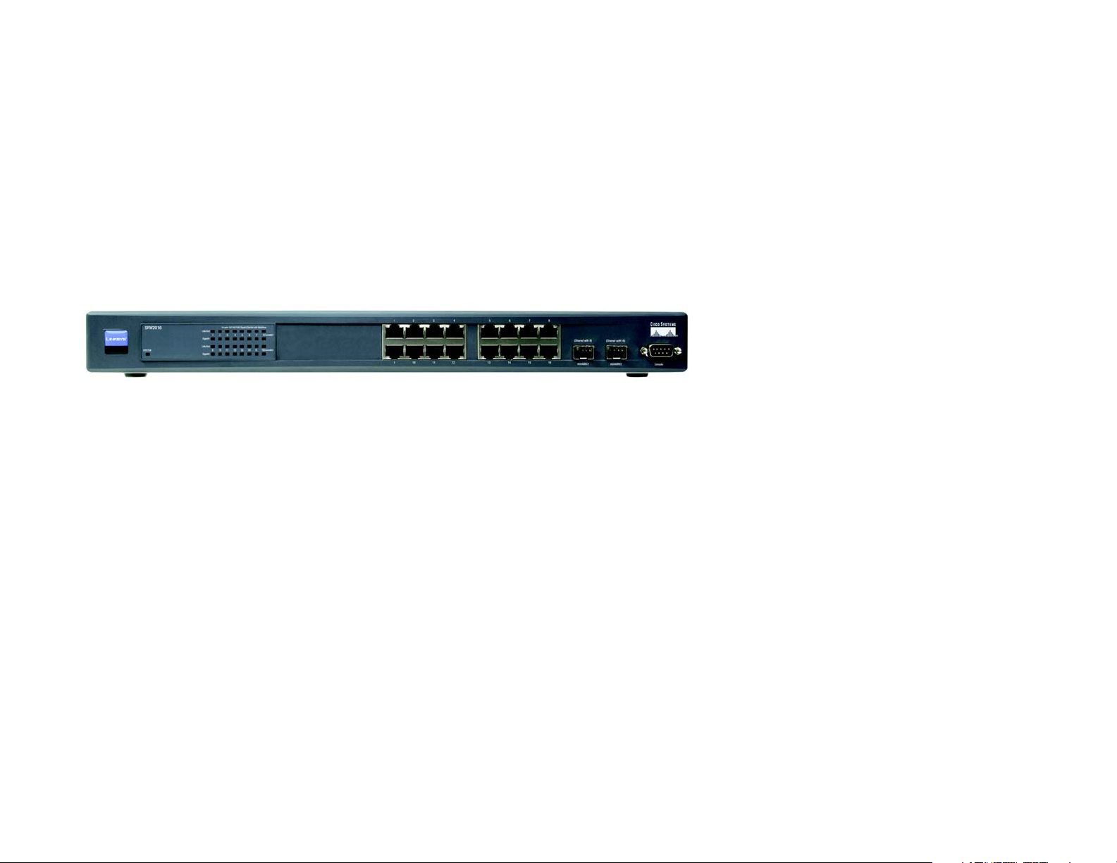
The Front Panel
The Switch's LEDs and ports are located on the front panel.
Figure 2-1: Front Panel of the 16-Port Switch
LEDs
SYSTEM Green. The SYSTEM LED lights up to indicate that the Switch is powered on.
Link/Act Green. The Link/Act LED lights up to indicate a functional network link through the
corresponding port (1 through 16, 24, or 48) with an attached device. It flashes to indicate
that the Switch is actively sending or receiving data over that port.
Gigabit Orange. The Gigabit LED lights up to indicate a Gigabit connection on the corresponding
port (1 through 16, 24, or 48).
Ports
1-48 The Switch is equipped with 16, 24, or 48 auto-sensing, Ethernet network ports, which use
RJ-45 connectors. The Fast Ethernet ports support network speeds of 10Mbps or
100Mbps, while the Gigabit Ethernet ports support network speeds of 10Mbps, 100Mbps,
and 1000Mbps. They can operate in half and full-duplex modes. Auto-sensing technology
enables each port to automatically detect the speed of the device connected to it (10Mbps,
100Mbps, or 1000Mbps), and adjust its speed and duplex accordingly.
Chapter 2: Getting to Know the Switch
Overview
3
Page 14
WebView Switches
For the 16-Port Switch, ports 8 and 16 are shared with miniGBIC1 and miniGBIC2,
respectively. For the 24-Port Gigabit Ethernet Switch, ports 12 and 24 are shared with
miniGBIC1 and miniGBIC2, respectively.
NOTE: If shared ports are both connected, then the miniGBIC port has priority.
miniGBIC1/2 The Switch provides two mini-GBIC ports. The mini-GBIC (gigabit interface converter) port
is a connection point for a mini-GBIC expansion module, so the Switch can be uplinked via
fiber to another switch. Each mini-GBIC port provides a link to a high-speed network
segment or individual workstation at speeds of up to 1000Mbps.
Use the Linksys MGBT1, MGBSX1, or MGBLH1 mini-GBIC modules with the Switch. The
MGBSX1 and the MGBLH1 require fiber cabling with LC connectors, while the MGBT1
requires a Category 5e Ethernet cable with an RJ-45 connector.
Console The Console port is where you can connect a serial cable to a PC’s serial port for
configuration using your PC’s HyperTerminal program. Refer to Chapter 4: Using the
Console Interface for Configuration for more information.
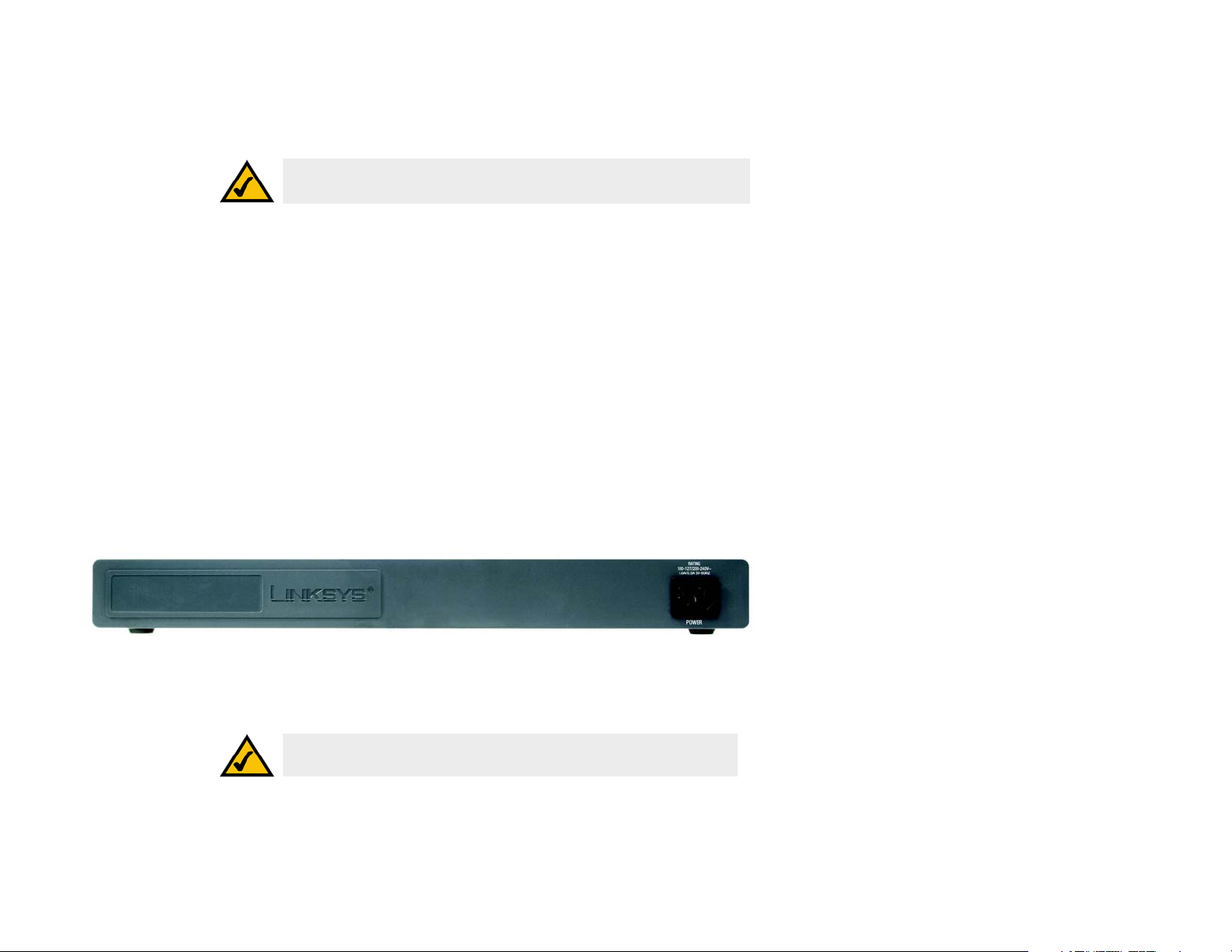
The Back Panel
The power port is located on the back panel of the Switch.
Figure 2-2: Back Panel of the 16-Port Switch
Power The Power port is where you will connect the power cord.
NOTE: If you need to reset the Switch, unplug the power cord from the back
of the Switch. Wait a few seconds and then reconnect it.
Chapter 2: Getting to Know the Switch
The Back Panel
4
Page 15
WebView Switches
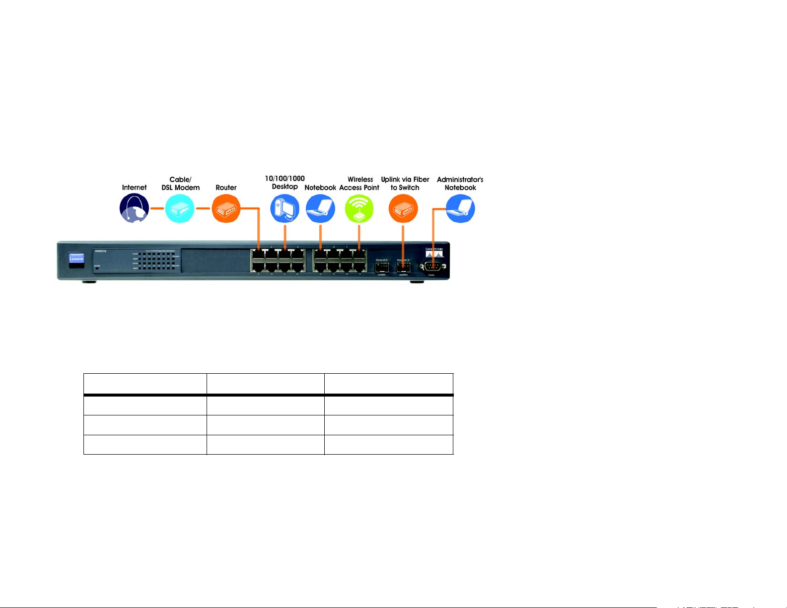
Chapter 3: Connecting the Switch
Overview
This chapter will explain how to connect network devices to the Switch. For an example of a typical network
configuration, see the application diagram shown below.
Figure 3-1: Typical Network Configuration for the 16-Port Switch
When you connect your network devices, make sure you don’t exceed the maximum cabling distances, which are
listed in the following table:
Table 1: Maximum Cabling Distances
From To Maximum Distance
Switch Switch or Hub* 100 meters (328 feet)
Hub Hub 5 meters (16.4 feet)
Switch or Hub Computer 100 meters (328 feet)
*A hub refers to any type of 100Mbps hub, including regular hubs and stackable hubs. A 10Mbps hub connected
to another 10Mbps hub can span up to 100 meters (328 feet).
Chapter 3: Connecting the Switch
Overview
5
Page 16

WebView Switches
Before You Install the Switch...
When you choose a location for the Switch, observe the following guidelines:
• Make sure that the Switch will be accessible and that the cables can be easily connected.
• Keep cabling away from sources of electrical noise, power lines, and fluorescent lighting fixtures.
• Position the Switch away from water and moisture sources.
• To ensure adequate air flow around the Switch, be sure to provide a minimum clearance of two inches
(50 mm).
• Do not stack free-standing Switches more than four units high.
Placement Options
Before connecting cables to the Switch, first you will physically install the Switch. Either set the Switch on its four
rubber feet for desktop placement or mount the Switch in a standard-sized, 19-inch wide, 1U high rack for rackmount placement.
Desktop Placement
1. Attach the rubber feet to the recessed areas on the bottom of the Switch.
2. Place the Switch on a desktop near an AC power source.
3. Keep enough ventilation space for the Switch and check the environmental restrictions mentioned in the
specifications.
4. Proceed to the section, “Connecting the Switch.”
Chapter 3: Connecting the Switch
Before You Install the Switch...
6
Page 17
WebView Switches
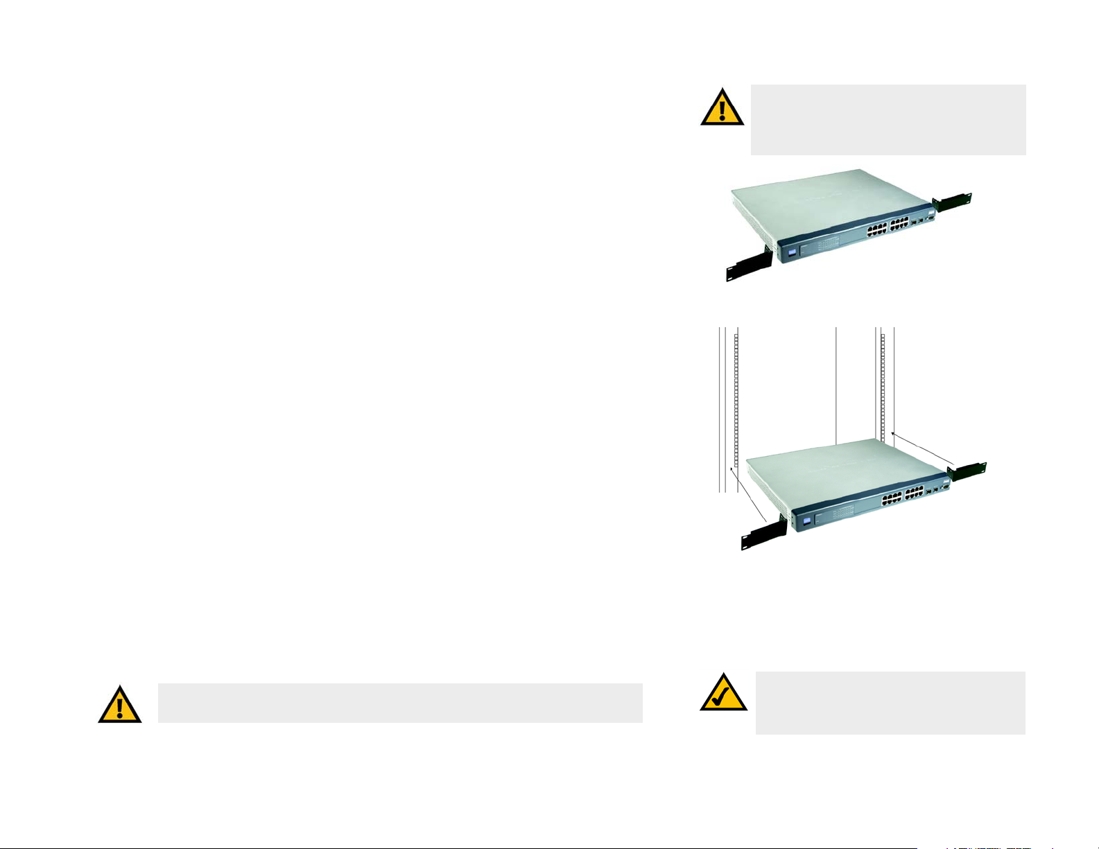
Rack-Mount Placement
To mount the Switch in any standard-sized, 19-inch wide, 1U high rack, follow these instructions:
1. Place the Switch on a hard flat surface with the front panel facing you.
2. Attach a rack–mount bracket to one side of the Switch with the supplied screws. Then attach the other
bracket to the other side.
3. Make sure the brackets are properly attached to the Switch.
4. Use the appropriate screws (not included) to securely attach the brackets to your rack.
5. Proceed to the section, “Connecting the Switch.”
Connecting the Switch
To connect network devices to the Switch, follow these instructions:
1. Make sure all the devices you will connect to the Switch are powered off.
2. For a 10/100Mbps devices, connect a Category 5 Ethernet network cable to one of the numbered ports on the
Switch. For a 1000Mbps device, connect a Category 5e Ethernet network cable to one of the numbered ports
on the Switch.
3. Connect the other end to a PC or other network device.
IMPORTANT: Make sure you use the screws
supplied with the mounting brackets. Using the
wrong screws could damage the Switch and would
invalidate your warranty.
Figure 3-2: Attach the Brackets to the Switch
4. Repeat steps 2 and 3 to connect additional devices.
5. If you are using the mini-GBIC port, then connect the mini-GBIC module to the mini-GBIC port. For detailed
instructions, refer to the module’s documentation.
6. If you will use the Switch’s console interface to configure the Switch, then connect the supplied serial cable
to the Switch’s Console port, and tighten the captive retaining screws. Connect the other end to your PC’s
serial port. (This PC must be running the VT100 terminal emulation software, such as HyperTerminal.)
7. Connect the supplied power cord to the Switch’s power port, and plug the other end into an electrical outlet.
IMPORTANT: Make sure you use the power cord that is supplied with the Switch. Use of a
different power cord could damage the Switch.
Chapter 3: Connecting the Switch
Connecting the Switch
Figure 3-3: Mount the Switch in the Rack
NOTE: If you need to reset the Switch, unplug the
power cord from the back of the Switch. Wait a
few seconds and then reconnect it.
7
Page 18

WebView Switches
8. Power on the network devices connected to the Switch. Each active port’s corresponding Link/Act LED will
light up on the Switch. If a port has an active Gigabit connection, then its corresponding Gigabit LED will also
light up.
If you will use the Switch’s console interface to configure the Switch, proceed to Chapter 4: Using the
Console Interface for Configuration for directions.
If you will use the Switch’s Web-based Utility to configure the Switch, proceed to Chapter 5: Using the
Web-based Utility for Configuration.
Chapter 3: Connecting the Switch
Connecting the Switch
8
Page 19
WebView Switches
Chapter 4: Using the Console Interface for Configuration
Overview
The Switch features a menu-driven console interface for basic configuration of the Switch and management of
your network. The Switch can be configured using CLI through the console interface or through a telnet
connection. This chapter describes console interface configuration. Configuration can also be performed through
the web utility, which is covered in the next chapter.
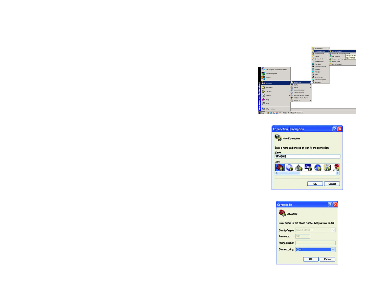
Configuring the HyperTerminal Application
Before you use the console interface, you will need to configure the HyperTerminal application on your PC.
1. Click the Start button. Select Programs and choose Accessories. Select Communications. Select
HyperTerminal from the options listed in this menu.
2. On the Connection Description screen, enter a name for this connection. In the example, the name of
connection is SRW2016. Select an icon for the application. Then, click the OK button.
3. On the Connect To screen, select a port to communicate with the Switch: COM1, COM2, or TCP/IP.
Figure 4-1: Finding HyperTerminal
Figure 4-2: Connection Description
Chapter 4: Using the Console Interface for Configuration
Overview
Figure 4-3: Connect To
9
Page 20
WebView Switches
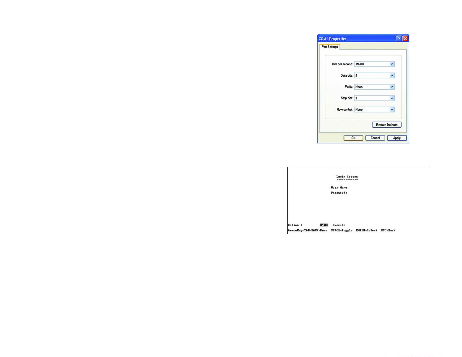
4. Set the serial port settings as follows:
Bits per second: 38400
Data bits: 8
Parity: None
Stop bits: 1
Flow control: None
Then, click the OK button.
Connecting to the Switch through a Telnet Session
Open a command line editor and enter telnet 192.168.1.254. Then, press the Enter key.
Figure 4-4: COM1 Properties
The Login screen will now appear. The first time you open the CLI interface, select Edit and enter admin in the
User Name field. Leave the Password field blank.
Press the Esc button and you will return to the login screen. Then, select Enter to enter the CLI interface.
Chapter 4: Using the Console Interface for Configuration
Connecting to the Switch through a Telnet Session
Figure 4-5: Telnet Login screen
10
Page 21
WebView Switches
Configuring the Switch through the Console Interface
The console screens consist of a series of menus. Each menu has several options, which are listed vertically. You
select a menu option when you highlight it; pressing the Enter key activates the highlighted option.
To navigate through the menus and actions of the console interface, use the up or down arrow keys to move up
or down, and use the left or right arrow keys to move left or right. Use the Enter key to select a menu option, and
use the Esc key to return to the previous selection. Menu options and any values entered or present will be
highlighted. The bottom of the screen lists the actions available.
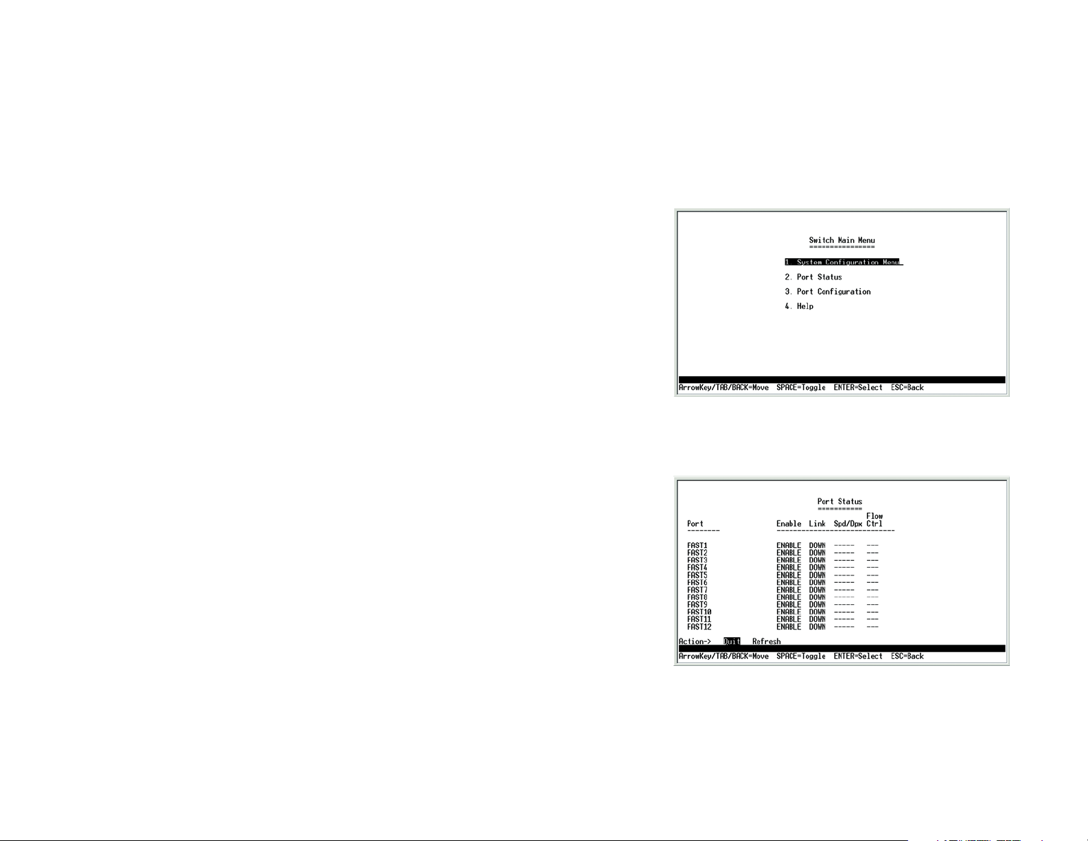
Switch Main Menu
The System Main Menu screen displays these choices:
1. System Configuration Information Menu
2. Port Status
3. Port Configuration
4. Help
Port Status
On the Switch Main Menu screen, select Port Status and press the Enter key if you want to view the status
information for the Switch’s ports.
The Port Status screen displays the port numbers, their status, Link status, speed and duplex mode, and status
of flow control, which is the flow of packet transmissions.
If you want to change any settings for a port, you must use the Port Configuration screen.
Chapter 4: Using the Console Interface for Configuration
Configuring the Switch through the Console Interface
Figure 4-6: Switch Main Menu
Figure 4-7: Port Status
11
Page 22
WebView Switches
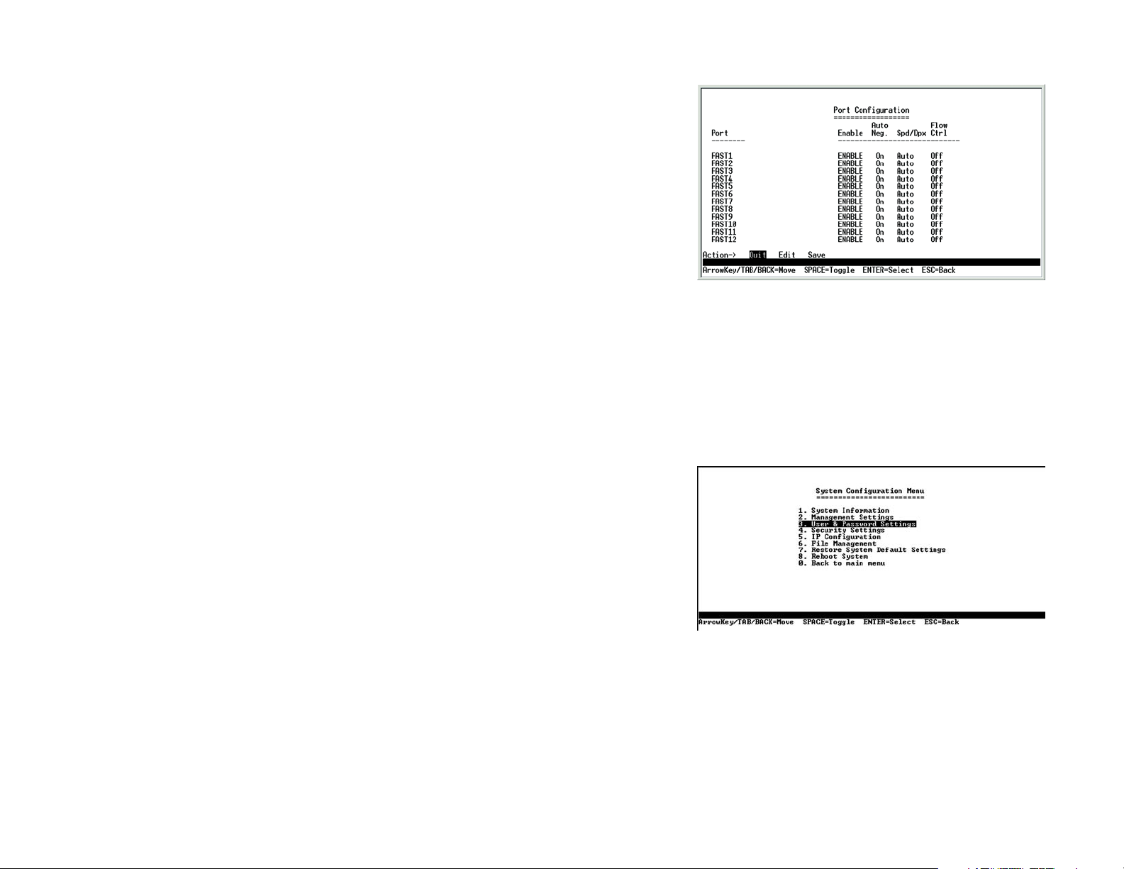
Port Configuration
On the Switch Main Menu screen, select Port Configuration and press the Enter key if you want to configure the
Switch’s ports.
The Port Configuration screen displays the port numbers, their status, auto-negotiation status, speed and duplex
mode, and status of flow control, which is the flow of packet transmissions.
Select Edit to make changes. When your changes are complete, press the Esc key to return to the Action menu,
and select Save to save your changes.
Help
Select Help and press the Enter key if you want to view the help information. This screen explains how to
navigate the various screens of the console interface.
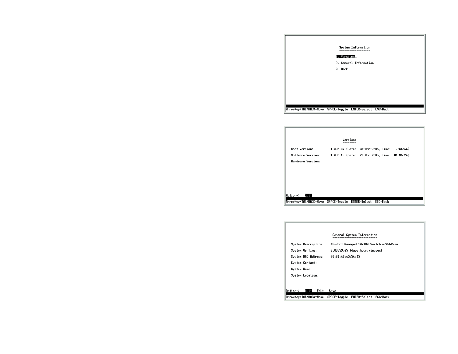
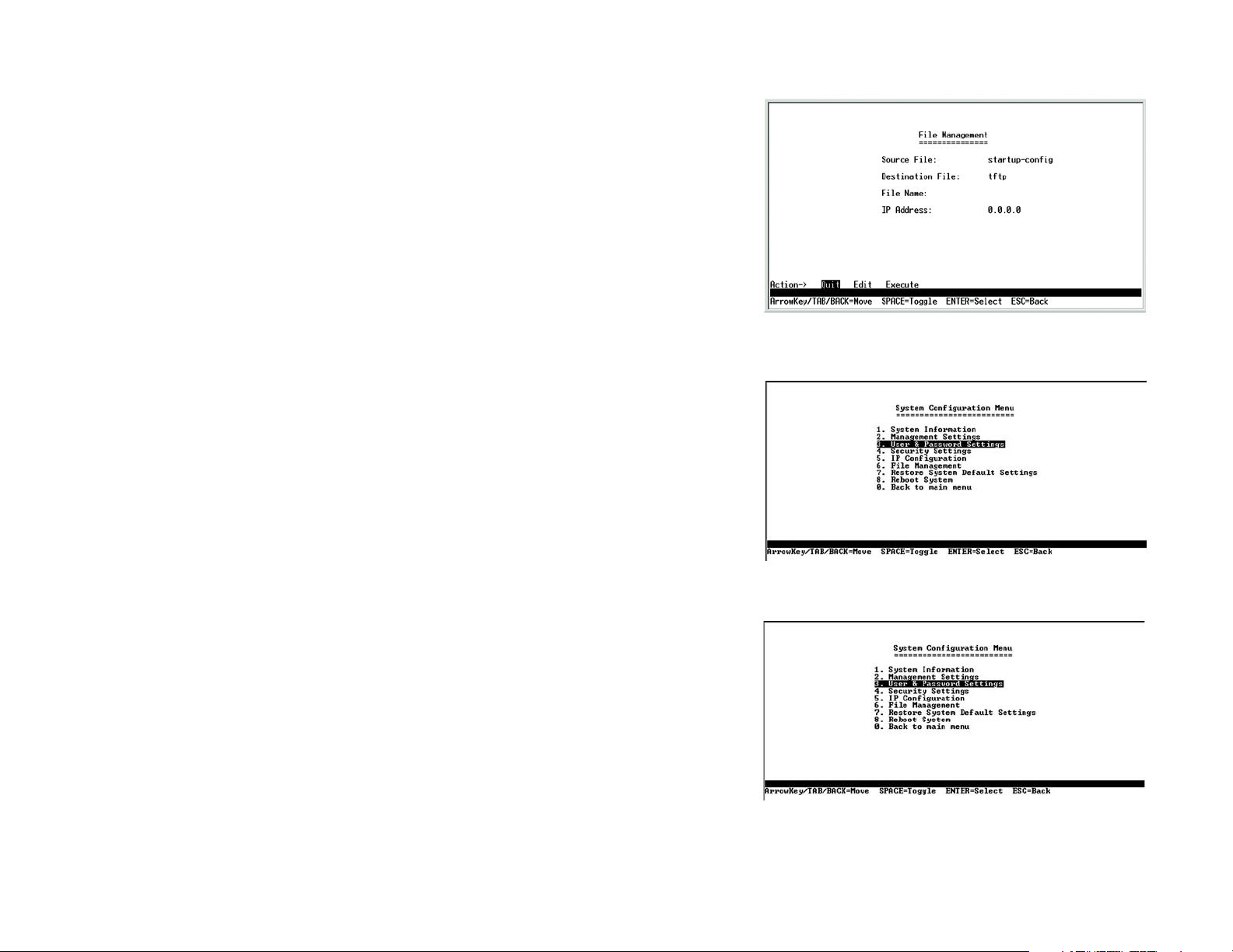
System Configuration Menu
On the System Configuration Menu screen, you have these choices:
1. System Information
2. Management Settings
3. User & Password Settings
4. Security Settings
5. IP Configuration
6. File Management
7. Restore System Default Settings
8. Reboot System
Figure 4-8: Port Configuration
Figure 4-9: System Configuration Menu
0. Back to main menu
Chapter 4: Using the Console Interface for Configuration
Configuring the Switch through the Console Interface
12
Page 23
WebView Switches
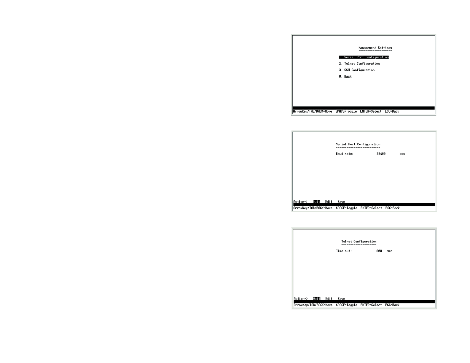
System Information
Using this screen, you can check the Switch’s firmware versions and general system information.
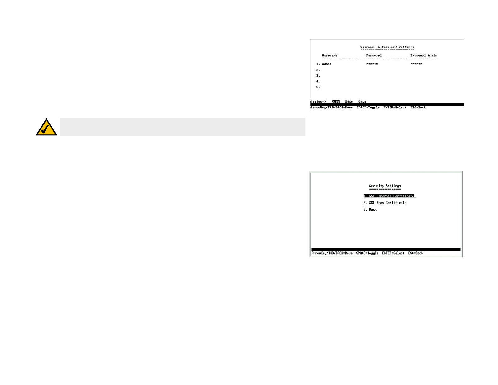
Versions
The Versions screen displays the Switch’s boot, software, and hardware firmware versions.
Figure 4-10: System Information Menu
General System Information
The General System Information screen displays the Switch’s description, System Up Time, System MAC
Address, System Contact, System Name, and System Location.
Select Edit to make changes. When your changes are complete, press the Esc key to return to the Action menu,
and select Save to save your changes.
Chapter 4: Using the Console Interface for Configuration
Configuring the Switch through the Console Interface
Figure 4-11: Versions
Figure 4-12: General System Information
13
Page 24
WebView Switches
Management Settings
From the Management Settings screen, you can set Serial Port Session Configuration, Telnet Session
Configuration, or Secure Telnet (SSH) Configuration.
Serial Port Configuration
On the Serial Port Configuration screen, the Switch’s baud rate is displayed.
Select Edit to make changes. When your changes are complete, press the Esc key to return to the Action menu,
and select Save to save your changes.
Figure 4-13: Management Settings Menu
Telnet Configuration
On the Telnet Configuration screen, the time-out is displayed.
Select Edit to make changes. When your changes are complete, press the Esc key to return to the Action menu,
and select Save to save your changes.
Chapter 4: Using the Console Interface for Configuration
Configuring the Switch through the Console Interface
Figure 4-14: Serial Port Configuration
Figure 4-15: Telnet Configuration
14
Page 25
WebView Switches
Username & Password Settings
From this sceen, you can administer the user names and passwords of those accessing the Switch.
NOTE: The Username & Password Settings screen can also be used to set passwords for other users.
Security Settings
The Security Settings screen enables you to configure security settings on the Switch, as well as generate and
display the certificate.
Figure 4-16: Username & Password Settings
Figure 4-17: Security Settings
Chapter 4: Using the Console Interface for Configuration
Configuring the Switch through the Console Interface
15
Page 26

WebView Switches
SSL Certificate Generation
Use the Certificate Generation screen to specify a device-generated certificate.
The following fields are specified:
Public Key Length - Specifies the SSL RSA key length. (Range: 512 - 2048)
Organization Name - Specifies the organization name. (Range: 1 - 64)
Locality or City Name - Specifies the location or city name. (Range: 1 - 64)
State or Province Name - Specifies the state or province name. (Range: 1 - 64)
Country Name - Specifies the country name. (Range: 2 - 2)
Validity Term - Specifies number of days certification is valid. (Range: 30 - 3650)
SSL_Certificate_Generation.bmp
Show Certificate
Figure 4-18: SSL Certificate Generation
Use the Show Certificate screen to display the internal certificate.
IP Configuration
The IP Configuration screen displays these choices: the Switch’s IP Address Settings, HTTP, HTTPS Configuration
and Network Configuration.
Chapter 4: Using the Console Interface for Configuration
Configuring the Switch through the Console Interface
Figure 4-19: SSL Certificate
Figure 4-20: IP Configuration
16
Page 27
WebView Switches
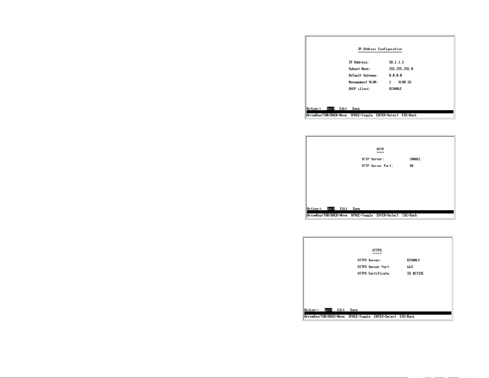
IP Address Configuration
The Switch’s IP information is displayed here.
IP Address. The IP Address of the Switch is displayed. (The default IP address is 192.168.1.254.) Verify that the
address you enter is correct and does not conflict with another device on the network.
Subnet Mask. The subnet mask of the Switch is displayed.
Default Gateway. The IP address of your network’s default gateway is displayed.
Management VLAN. The VLAN ID number is displayed.
DHCP client. The status of the DHCP client is displayed. If you want the Switch to be a DHCP client, then select
ENABLE. If you want to assign an static IP address to the Switch, then enter the IP settings and select DISABLE.
Select Edit to make changes. When your changes are complete, press the Esc key to return to the Action menu,
and select Save to save your changes.
HTTP
The HTTP screen displays the status and port number of the HTTP Server.
For the 24-Port Switch, there is also an HTTP Authentication setting. You can set the authentication method for up
to four users of the Switch’s Web-based Utility. Select LOCAL if you want access protected by a username and
password. Select RADIUS if you want to use authentication via a RADIUS server. Select TACACS if you want
access protected by the TACACS authentication protocol, which uses a username and password. Select DENY if
you want to block access (for example, if you want to allow fewer than four users).
Select Edit to make changes. When your changes are complete, press the Esc key to return to the Action menu,
and select Save to save your changes.
HTTPS Configuration
Use the HTTPS Configuration screen to configure HTTPS settings. You can enable or disable the HTTPS server
and configure the port on which the session is enabled.
Figure 4-21: IP Address Configuration
Figure 4-22: HTTP
Chapter 4: Using the Console Interface for Configuration
Configuring the Switch through the Console Interface
Figure 4-23: HTTPS Configuration
17
Page 28
WebView Switches
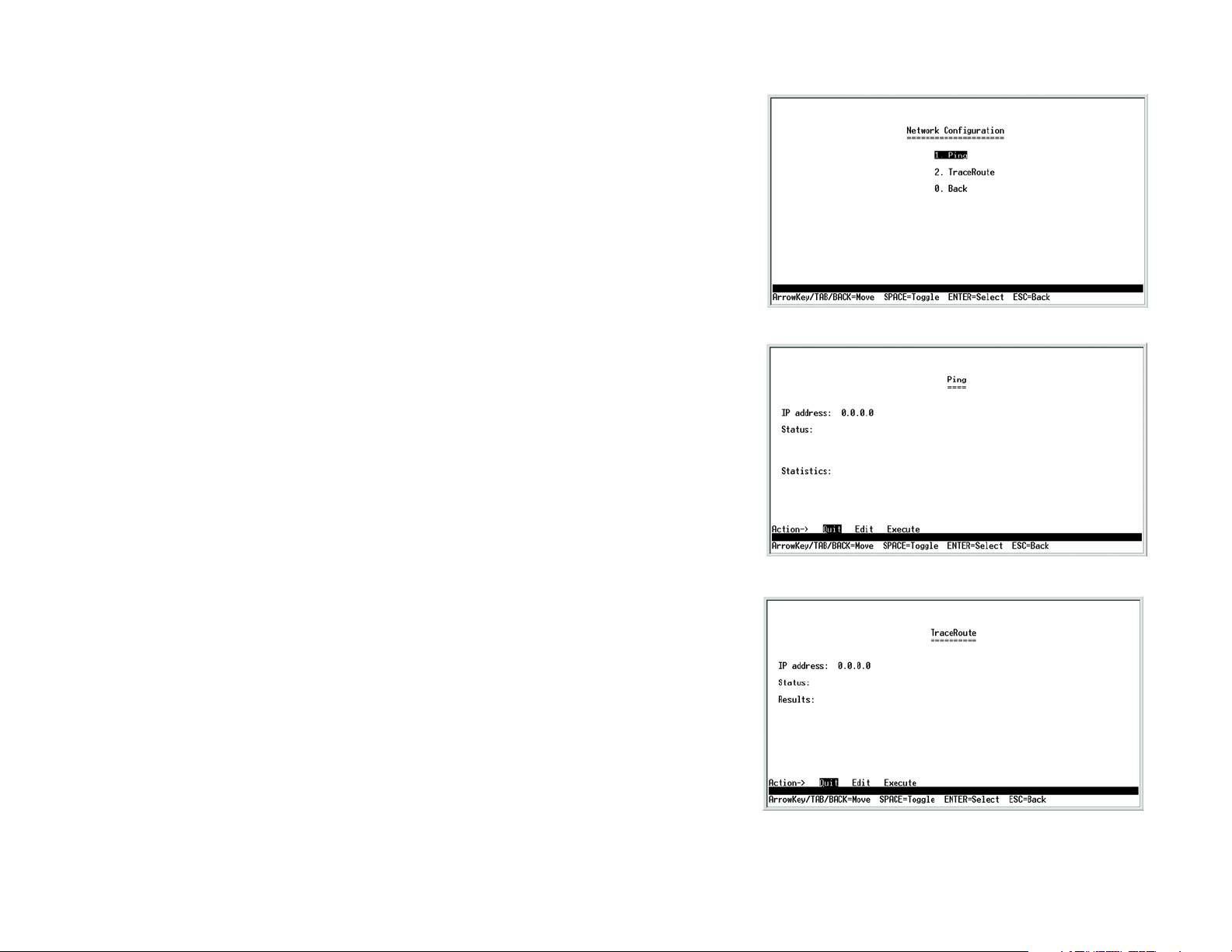
Network Configuration
The Network Configuration screen offers a choice of two tests, Ping and TraceRoute.
Ping
The Ping screen displays the IP address of the location you want to contact.
Select Edit to change the IP address, and select Execute to begin the ping test.
After the ping test is complete, the Ping screen displays the IP address, status, and statistics of the ping test.
Select Edit to make changes. When your changes are complete, press the Esc key to return to the Action menu,
and select Save to save your changes.
Figure 4-24: Network Configuration
TraceRoute
The TraceRoute screen displays the IP address of the address whose route you want to trace.
Select Edit to change the IP address, and select Execute to begin the traceroute test.
After the traceroute test is complete, the TraceRoute screen displays the IP address, status, and statistics of the
traceroute test.
Select Edit to make changes. When your changes are complete, press the Esc key to return to the Action menu,
and select Save to save your changes.
Chapter 4: Using the Console Interface for Configuration
Configuring the Switch through the Console Interface
Figure 4-25: Ping Test
Figure 4-26: TraceRoute Test
18
Page 29
WebView Switches
File Management
The File Management screen allows you to upload or download files, such as the startup configuration, boot, or
image file, using a TFTP server.
Select Edit to change the settings. When your changes are complete, press the Esc key to return to the Action
menu, and select Execute to upload or download the designated file. After you download a file to the Switch, it
may need to be rebooted.
Restore System Default Settings
To restore the Switch back to the factory default settings, select Restore System Default Settings and press
the Enter key. You will be asked if you want to continue. Press the y key to restore the Switch’s default settings,
or press the n key to cancel.
Figure 4-27: File Management
Reboot System
Select Reboot System and press the Enter key if you want to restart the Switch. You will be asked if you want to
continue. Press the y key to reboot the Switch, or press the n key to cancel. After the Switch has rebooted, the
Switch Main Menu screen will appear.
Back to main menu
Select Back to main menu and press the Enter key if you want to return to the Switch Main Menu screen.
Chapter 4: Using the Console Interface for Configuration
Configuring the Switch through the Console Interface
Figure 4-28: Restore System Default Settings
Figure 4-29: Reboot System
19
Page 30
WebView Switches
Chapter 5: Using the Web-based Utility for Configuration
Overview
This chapter describes the features included in the Web-based utility. All of the features shown in this chapter,
unless specifically identified, are included in the Fast Ethernet switches. Additional features for the Gigabit
switches are specified with images for the Gigabit Ethernet’s utility included.
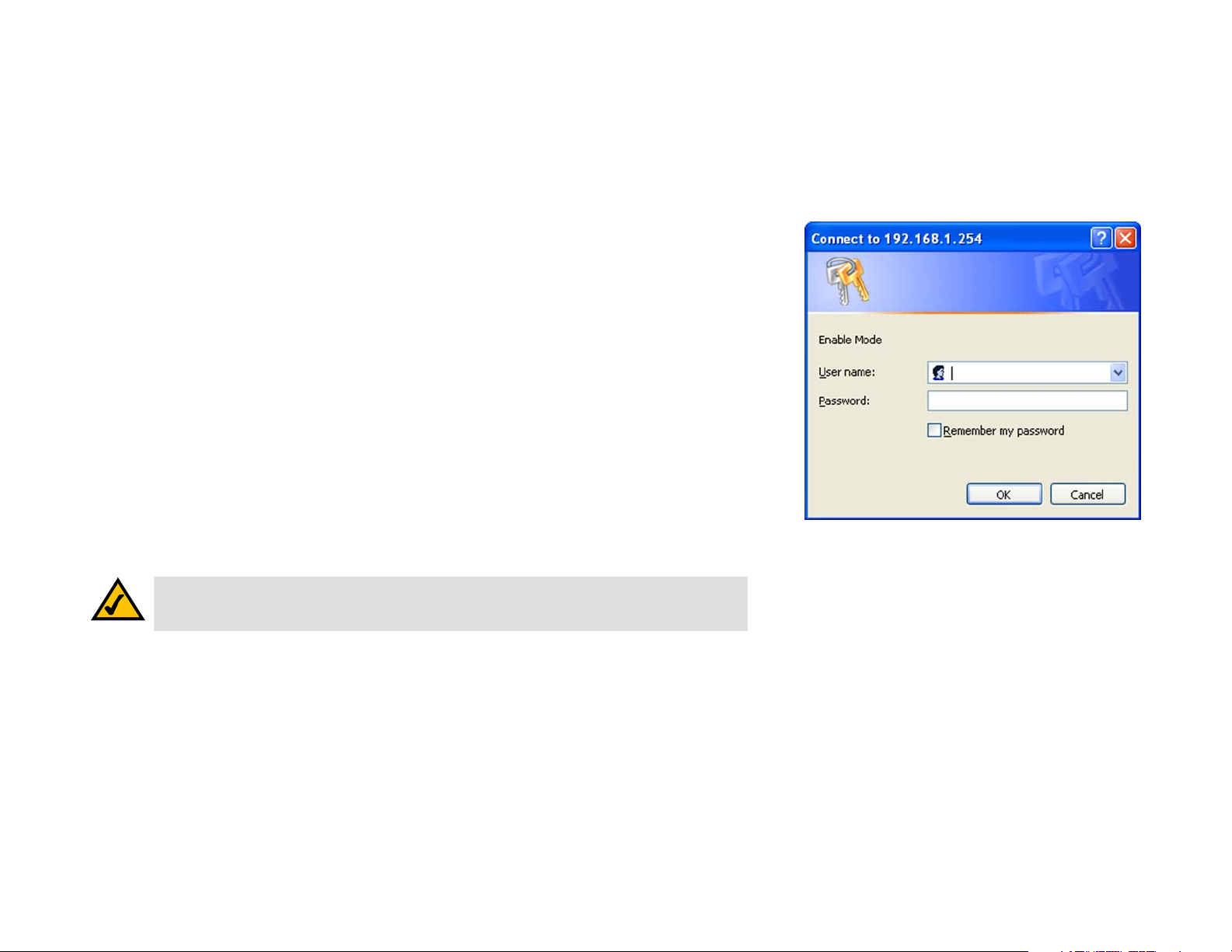
Accessing the Web-based Utility
Open your web browser and enter 192.168.1.254 into the Address field. Press the Enter key and the login
screen will appear. The first time you open the Web-based Utility, enter admin in the User Name field, and leave
the Password field blank. Click the OK button. You can set a password later from the System Password screen.
The first screen that appears is the System Description screen. This allows you to access six main tabs: Sys. Info.
(System Information), IP Conf. (Configuration), Switch Conf. (Configuration), QoS (Quality of Service), Security,
SNTP (Simple Network Time Protocol), Statistics, Logs, Maintenance, and Help. Click one of the main tabs to view
additional tabs.
An About button appears at the top of each screen. Clicking this button will bring up the versioning information of
the Switch. The LEDs on the screen display status information about their corresponding ports. A green LED
indicates a connection, while a blue LED indicates no connection. When you click a port’s LED, the statistics for
that port are displayed.
Figure 5-1: Login Screen
NOTE: The LEDs displayed in the Web-based Utility are not the same as the LEDs on the front panel
of the Switch. The front panel LEDs display different status information, which is described in
Chapter 2: Getting to Know the Switch.
Chapter 5: Using the Web-based Utility for Configuration
Overview
20
Page 31

WebView Switches
Sys. Info. (System Information) Tab - System Description
The System Description screen lets you enter general information about the Switch.
Model Name. This is the model number and name of the Switch.
System Name. Enter a name for the Switch.
System Location. Describe the location of the Switch.
System Contact. Enter the name of the contact person for this Switch.
System Object ID. The vendor's authoritative identification of the network management subsystem contained in
the entity.
System up time. This displays the amount of time that has elapsed since the Switch was last reset.
IP Address. This is the IP address of the Switch.
Base MAC Address. This is the MAC address of the Switch.
Hardware Version. Displayed here is the version number of the Switch’s hardware.
Software Version. Displayed here is the version number of the Switch’s software.
Figure 5-2: System Information - System Description
Click the Submit button to save your changes.
Sys. Info. (System Information) Tab - System Mode
This screen appears in the Web-based utility for the Gigabit Ethernet switches ONLY. The System Mode
screen allows you to enable or disable the Jumbo Frames feature. Jumbo Frames enable the travel of identical
data in fewer frames; this promotes faster data transmissions.
Jumbo Frames. If you want to enable this feature on the Switch, select Enabled. You will be notified that this
feature will be enabled after the Switch is reset. Otherwise, select Disabled.
Click the Submit button to save your changes.
Chapter 5: Using the Web-based Utility for Configuration
Sys. Info. (System Information) Tab - System Description
Figure 5-3: System Information - System Mode
NOTE: The System Mode screen applies to the Gigabit
Ethernet switches ONLY.
21
Page 32

WebView Switches
Sys. Info. (System Information) Tab - Forwarding Database
The Forwarding Database screen lets you define the aging interval of the Switch.
Aging Interval (15-630) (secs). This specifies the aging-out period on the Forwarding Database.
Click the Submit button to save your changes.
A table of VLAN (Virtual Local Area Network) entries is listed.
VLAN ID. Displayed here is the ID number of the VLAN for this entry.
MAC Address. This is the MAC address of the entry.
Port. This is the port number for this entry.
ifIndex. This is the interface for this entry.
Status. This indicates how the entry was created, Dynamic (dynamically learned) or Static (statically configured).
You can add or edit a forwarding interface by clicking the icon that looks like a sheet of paper. This will allow you
to configure the following settings:
Interface. Select the appropriate interface, either a port number or LAG (Link Aggregation Group) number.
MAC Address. Enter the MAC address for this entry.
VLAN ID. If you want to use a VLAN ID, then select the radio button and enter the ID number of the VLAN.
VLAN Name. If you want to use a VLAN Name, select the radio button and then enter a name here.
Status. Select the status of your entry, Permanent, Delete On Reset, or Delete On Time Out.
Click the Submit button to save your changes.
Figure 5-4: System Information - Forwarding Database
Figure 5-5: Forwarding Database - Add Entry
Chapter 5: Using the Web-based Utility for Configuration
Sys. Info. (System Information) Tab - Forwarding Database
22
Page 33

WebView Switches
Sys. Info. (System Information) Tab - Time Synchronization
The Time Synchronization screen allows you to configure the time settings for the Switch.
Clock Source. If you want to set the system clock via an SNTP (Simple Network Time Protocol) server, then select
SNTP. Otherwise, select None.
Local Settings
Date. Specify the system date here.
Local Time. Specify the system time here.
Time Zone Offset. Enter the difference between Greenwich Mean Time (GMT) and local time.
Daylight Saving. Select Daylight Saving to enable it on the Switch. If the Switch should use US daylight
savings, then select USA. If the Switch should use EU daylight savings, then select European. If it should use
another kind of daylight savings, then select Other and complete the From and To fields.
Time Set Offset (1-1440). For non-US and European countries, specify the amount of time for daylight savings.
The default is 60 minutes.
From. If you selected Other for the Daylight Saving setting, then enter the date and time when daylight savings
begins.
Figure 5-6: System Information - Time Synchronization
To. If you selected Other for the Daylight Saving setting, then enter the date and time when daylight savings ends.
Recurring. If you selected Other for the Daylight Saving setting and daylight savings has the same start and end
dates and times every year, then select Recurring.
From. If you selected Recurring, then enter the date and time when daylight savings begins.
To. If you selected Recurring, then enter the date and time when daylight savings ends.
Click the Submit button to save your changes.
Chapter 5: Using the Web-based Utility for Configuration
Sys. Info. (System Information) Tab - Time Synchronization
23
Page 34

WebView Switches
IP Conf. (Configuration) Tab - IP Addr. (Address)
The IP Address screen allows you to assign DHCP or static IP settings to interfaces and assign default gateways.
DHCP Interface. If you are using the DHCP Interface, then select the radio button and specify the VLAN on which
the DHCP IP address is configured.
Host Name. Enter the DHCP Host Name here.
Static Address. If you are using a static IP address, then select the radio button and enter the IP settings.
IP Address. Enter the interface IP address.
Mask. Enter the subnet mask of the currently configured IP address.
Default Gateway. Enter the IP address of the Default Gateway. To delete the Default Gateway setting, click the
red X to the right.
Current Management Interface. Specify the interface used to manage the Default Gateway.
Click the Submit button to save your changes. Before any changes are incorporated into the Web-based utility,
you must first return to the System Description screen on the System Information tab and click your web
browser’s Refresh button.
Figure 5-7: IP Configuration - IP Address
Chapter 5: Using the Web-based Utility for Configuration
IP Conf. (Configuration) Tab - IP Addr. (Address)
24
Page 35

WebView Switches
Switch Conf. (Configuration) Tab - Interface Conf. (Configuration)
The Interface Configuration screen shows you the settings for each of the Switch’s ports. Where many ports are
present, you can scroll to the right on the screen to view the settings for further ports.
Interface#. This is the port number.
Name. This is the device port ID.
Edit. The next row shows which port is selected or modified (according to the buttons at the bottom of the
screen. Click the radio button in the port’s row to select that port before clicking either button at the bottom of the
screen.
Port Type. This is the port type.
Port Status. Displayed here is the status of the port.
Port Speed. Displayed here is the configured rate for the port. The speed can be configured only when auto-
negotiation is disabled on that port.
Duplex Mode. This is the port duplex mode, Full (transmission occurs in both directions simultaneously) or Half
(transmission occurs in only one direction at a time). This mode can be configured only when auto-negotiation is
disabled and port speed is set to 10Mbps or 100Mbps. It cannot be configured on Link Aggregation Groups
(LAGs).
Auto Negotiation. This is the status of the port’s Auto Negotiation feature.
Back Pressure. Displayed here is the status of the port’s Back Pressure mode, which is used with Half Duplex
Mode to disable ports from receiving messages. This mode is used for ports in Half Duplex Mode or on LAGs.
Flow Control. This is the flow control status of the port. It is active when the port uses Full Duplex Mode.
MDI/MDIX. This is the MDI/MDIX status of the port. The Auto setting is used when you want the port to
automatically detect the cable type. The MDI setting is used if the port is connected to an end station. The MDIX
setting is used if the port is connected to a hub or another switch.
LAG. This indicates if the port is part of a LAG.
Storm Control. When enabled, the Storm Control setting prevents an excessive number of broadcast and
multicast messages.
Figure 5-8: Switch Configuration - Interface Configuration
Chapter 5: Using the Web-based Utility for Configuration
Switch Conf. (Configuration) Tab - Interface Conf. (Configuration)
25
Page 36

WebView Switches
PVE. For Gigabit Ethernet switches. When a port is a Private VLAN Edge (PVE) port, it bypasses the Forwarding
Database and forwards all unicast, multicast, and broadcast traffic to an uplink, except for MAC-to-me packets.
Uplinks can be ports or LAGs.
PVE. For Fast Ethernet switches. PVE Groups indicates the PVE group to which the port belongs. When an
uplink is configured for a port, all ports in that group are also protected by that uplink. PVE Uplink indicates the
uplink to which all traffic from a protected port is forwarded.
If you want to reset a port’s settings to its defaults, select a port by clicking the radio button for that port. Then,
click the Reset the settings of Selected Port to default button.
If you want to modify a port’s changes, select a port by clicking the radio button for that port. Then, click the
Modify the settings of Selected Port button. On the new screen that appears, you can change the port’s
settings. (Some settings shown may not be available, depending on the type of switch you have and other
settings you have configured for that port.)
Interface. This is the port number.
Description. Enter a description for this port.
Port Type. This is the port type.
Admin Status. Change the status of the port here.
Current Port Status. Displayed here is the status of the port.
NOTE: PVE is configured on a group of ports
for FE devices. This is done using the using the
PVE Mapping screen
Reactivate Suspended Port. If you want to reactivate a port that has been suspended, click the checkbox.
Operational Status. This indicates whether or not the port is active.
Admin Speed. Change the speed of the port here.
Current Port Speed. Displayed here is the current speed of the port.
Admin Duplex. Change the duplex mode here.
Current Duplex Mode. This is the duplex mode of the port.
Auto Negotiation. You can enable or disable the port’s Auto Negotiation feature.
Current Auto Negotiation. This is the current setting of the port’s Auto Negotiation feature.
Back Pressure. You can enable or disable the port’s Back Pressure feature.
Chapter 5: Using the Web-based Utility for Configuration
Switch Conf. (Configuration) Tab - Interface Conf. (Configuration)
Figure 5-9: Interface Configuration - Change Settings
26
Page 37

WebView Switches
Current Back Pressure. Displayed here is the status of the port’s Back Pressure mode.
Flow Control. You can enable or disable the port’s Flow Control feature.
Current Flow Control. This is the flow control status of the port.
MDI/MDIX. Select the Auto setting if you want the port to automatically detect the cable type. Select MDI if the
port is connected to an end station. Select MDIX if the port is connected to a hub or another switch.
Current MDI/MDIX. This is the current MDI/MDIX status of the port.
LA. This indicates if the port is part of a LAG.
Storm Control. You can enable or disable the port’s Storm Control setting.
PVE. For Gigabit Ethernet switches ONLY. When a port is a Private VLAN Edge (PVE) port, it bypasses the
Forwarding Database and forwards all unicast, multicast, and broadcast traffic to an uplink, except for MAC-tome packets. Uplinks can be ports or LAGs.
Click the Submit button to save your changes.
Chapter 5: Using the Web-based Utility for Configuration
Switch Conf. (Configuration) Tab - Interface Conf. (Configuration)
27
Page 38

WebView Switches
Switch Conf. (Configuration) Tab - VLAN
The VLAN screen displays subgroups of a LAN (Local Area Network).
Chose the Select VLAN ID or Show All option. If you chose to Select VLAN ID, chose the ID
you wish to display from the drop-down menu. The following information is displayed:
VLAN
ID. This displays the VLAN ID number.
Name. This can be up to 32 alphanumeric characters long and identifies the name assigned to the VLAN.
Type. Displayed here is the VLAN type: Dynamic (dynamically created), Static (created by user), or Default (the
Switch has one default VLAN).
Ports & LAGs. This shows the port of the column you selected or all of the ports with the following designations:
Member: Indicates the port's membership status in the VLAN, which can be:
S - Statistically included
D - Dynamically included
E - Excluded
F - Forbidden
Tagging: Indicates if the port is a tagged member with a T for "Tagged" or U for "Untagged".
To create a VLAN, click the Create icon on the far right of the screen. On the screen that appears, enter the VLAN
ID as well as the VLAN name. Chose the port, as well as the Member and Tagging type. Then, click the Submit
button.
Figure 5-10: Switch Configuration - VLAN
Figure 5-11: Switch Configuration - Create VLAN
Chapter 5: Using the Web-based Utility for Configuration
Switch Conf. (Configuration) Tab - VLAN
28
Page 39

WebView Switches
Switch Conf. (Configuration) Tab - VLAN Interface Settings
The VLAN Interface Settings screen lets you define properties of the interfaces that are associated with VLANs.
Interface. This is the physical address of the interface, Port or LAG.
Interface VLAN Mode. One of the following VLAN modes will appear
• General - The port belongs to VLANs, and each VLAN is user-defined as tagged or untagged (full 802.1q
mode).
• Access - The port belongs to a single, untagged VLAN. When a port is in Access mode, the packet tapes
accepted on the port cannot be designated. Ingress filtering cannot be enabled/disabled on an access
port.
• Trunk - The port belongs to VLANs in which all ports are tagged (except for one port that can be
untagged).
PVID. VLAN ID of untagged packets.
Frame Type. Packet type accepted on the port, Admit All (all packets are accepted) or VLAN Only (only VLAN
packets are accepted).
Ingress Filtering. Enables or disables Ingress filtering on the port. Ingress filtering discards packets that are
destined to VLANs of which the specific port is not a member.
To edit the interface settings for a particular VLAN, click the Edit icon, which resembles a pencil, for that
interface. On the screen that appears, you can settings for that interface. Click the Submit button when finished.
Chapter 5: Using the Web-based Utility for Configuration
Switch Conf. (Configuration) Tab - VLAN Interface Settings
Figure 5-12: Switch Configuration - VLAN Interface Settings
Figure 5-13: Switch Configuration - edit VLAN Interface
Settings
29
Page 40

WebView Switches
Switch Conf. (Configuration) Tab - GVRP Parameters
The name of this section is different depending on the type of Switch you are using. Gigabit Ethernet Switches
show the GVRP Parameters screen. Fast Ethernet Switches show the PVE Mapping screen
GVRP Parameters - Gigabit Ethernet Switches ONLY
GARP VLAN Registration Protocol (GVRP) is specifically provided for automatic distribution of VLAN membership
information among VLAN-aware bridges. GVRP allows VLAN-aware bridges to automatically learn VLANs to
bridge ports mapping, without having to individually configure each bridge and register VLAN membership.
GVRP Global Status. This indicates if GVRP is enabled on the Switch.
Interface. This dIsplays the interface/port on which GVRP is enabled.
GVRP State. This indicates if GVRP is enabled on the interface.
Dynamic VLAN Creation. This indicates if Dynamic VLAN creation is enabled on the interface.
GVRP Registration. This indicates if VLAN registration through GVRP is enabled on the interface.
To modify a GVRP, click the Edit icon, which looks like a pencil.
To apply changes made to a GVRP, click the Submit button.
NOTE: The GVRP Parameters screen applies to the
SRW2048 model ONLY.
Figure 5-14: Switch Configuration - GVRP Parameters
Switch Conf. (Configuration) Tab - PVE Mapping
PVE Mapping performs the same functions on the Fast Ethernet Switch , as configuring a PVE uplink, using the
interface screen on GE devices.
Group ID. This indicates the Group mapped on the Switch.
Group Members. This dIsplays the ports associated with this Group.
PVE Uplink. This indicates the type of PVE uplink.
To modify a PVE, click the Edit icon, which looks like a pencil.
Chapter 5: Using the Web-based Utility for Configuration
Switch Conf. (Configuration) Tab - GVRP Parameters
Figure 5-15: Switch Configuration - PVE Mapping
30
Page 41

WebView Switches
Switch Conf. (Configuration) Tab - LAG Conf. (Configuration)
The Switch supports up to eight Link Aggregated Groups (LAGs), which maximize port usage by linking a group of
ports together to form a single group. LAGs multiply the bandwidth between the network devices, increase port
flexibility, and provide link redundancy. The Switch’s LAGs are listed on the LA Configuration screen, which also
allows you to modify them.
LAG Port. This displays the LAG number.
Name. This is the port name.
Link State. Displayed here is the status of the link.
Member. This shows the ports configured to the LAG.
If you want to delete a current LAG, then select the LAG’s X icon.
To modify a LAG, click the LAG’s Edit icon, which resembles a pencil. On the new screen that appears, you can
modify the LAG for each of the Switch’s ports. Where many ports are present, you can scroll to the right on the
screen to view the settings for further ports.
LAG Port. This displays the LAG number.
LAG Name. Complete the LAG Name field.
Port. Select the ports you want to include in this LAG.
LACP. Select the ports for which you want to enable the use of Link Aggregation Control Protocol (LACP).
Activity. If checked, indicates that the port is an active member of the LAG. If not checked, indicates that it is a
LAG LAP candidate, but is not an active LAG member.
Click the Submit button to save your changes.
Figure 5-16: Switch Configuration - LAG Configuration
Figure 5-17: Switch Configuration - edit LAG Configuration
Chapter 5: Using the Web-based Utility for Configuration
Switch Conf. (Configuration) Tab - LAG Conf. (Configuration)
31
Page 42

WebView Switches
Switch Conf. (Configuration) Tab - Port Mirroring
The Port Mirroring screen lets you configure the Switch’s port mirroring settings. Port mirroring can be used for
diagnostics or debugging. It forwards copies of incoming and outgoing packets from one port to a monitoring
port.
Port to be Mirrored. Select the port number from which port traffic is mirrored.
Probe Port. Select the port number to which port traffic is copied.
Mode. Select the appropriate port mode configuration, RxOnly (receiving only), TxOnly (transmitting only), or
Both (receiving and transmitting).
Click the Submit button to save your changes.
Your port mirroring sessions are listed in a table.
Probe Port. This is the port number to which port traffic is copied.
Port To Be Mirrored. This is the port number from which port traffic is mirrored.
Copy Direction. This displays the traffic direction(s) being monitored.
Remove. If you want to delete a port mirroring session, click its Remove checkbox and the Remove button.
Figure 5-18: Switch Configuration - Port Mirroring
Chapter 5: Using the Web-based Utility for Configuration
Switch Conf. (Configuration) Tab - Port Mirroring
32
Page 43

WebView Switches
Switch Conf. (Configuration) Tab - LACP
The LACP screen allows you to enable the use of the Link Aggregation Control Protocol (LACP) on relevant links
for LAGs. Listed on this screen are the LACP LAGs.
LACP System Priority (1 - 65535). Select the LACP priority value for the system. Then, click the Submit button.
LACP information is displayed below, per port.
Port. This is the port number using LACP.
Port Priority. This is the LACP priority value for the port.
LACP Timeout. This is the administrative LACP timeout period, Short or Long.
Click the pencil-shaped Edit icon to modify settings for a port. A new screen will appear, displaying the available
LACP settings.
Port. Select the port you want.
LACP Port Priority. Select the LACP priority value for the port.
LACP Timeout. Select the LACP timeout period for this port, Short or Long.
Click the Submit button to save your changes.
Chapter 5: Using the Web-based Utility for Configuration
Switch Conf. (Configuration) Tab - LACP
Figure 5-19: Switch Configuration - LACP
Figure 5-20: LACP - Change Settings
33
Page 44

WebView Switches
Switch Conf. (Configuration) Tab - IGMP Snooping
When IGMP Snooping is enabled globally, all IGMP packets are forwarded to the CPU. The CPU analyzes the
incoming packets and determines:
Which ports want to join which Multicast groups.
Which ports have Multicast routers generating IGMP queries.
What routing protocols are forwarding packets and Multicast traffic.
Ports requesting to join a specific Multicast group issue an IGMP report, specifying that Multicast group is
accepting members. This results in the creation of the Multicast filtering database.
The IGMP Snooping page contains the following fields:
Enable IGMP Snooping Status. When this box is checked, IGMP Snooping is enabled on the Switch. IGMP
Snooping can be enabled only if Bridge Multicast Filtering is enabled.
VLAN ID. Specifies the VLAN ID.
IGMP Snooping Status. Indicates if IGMP snooping is enabled or disabled on the VLAN.
Enable Auto Learn. Indicates if Auto Learn is enabled or disabled on the Switch. If Auto Learn is enabled, the
Switch automatically learns where other Multicast groups are located.
Figure 5-21: Switch Configuration - IGMP Snooping
Host Timeout. Indicates the amount of time host waits to receive a message before timing out. The default time
is 260 seconds.
MRouter Timeout. Indicates the amount of the time the Multicast router waits to receive a message before it
times out. The default value is 300 seconds.
Leave Timeout. Indicates the amount of time the host waits, after requesting to leave the IGMP group and not
receiving a Join message from another station, before timing out. If a Leave Timeout occurs, the Switch notifies
the Multicast device to stop sending traffic The Leave Timeout value is either user-defined, or an immediate leave
value. The default timeout is 10 seconds.
Click the Edit icon, which looks like a pen, to edit any of the IGMP Snooping settings. Click the Submit button to
activate any changed you made on this screen.
Chapter 5: Using the Web-based Utility for Configuration
Switch Conf. (Configuration) Tab - IGMP Snooping
Figure 5-22: Switch Configuration - Edit IGMP Snooping
34
Page 45

WebView Switches
Switch Conf. (Configuration) Tab - Bridge Multicast
The Bridge Multicast screen displays the ports and LAGs attached to the Multicast service group. The Port and
LAG tables reflect the manner in which the port or LAG joined the Multicast group. Ports can be added either to
existing groups or to new Multicast service groups.
From this screen, you can view the VLAN ID for each of the Switch’s ports. Where many ports are present, you can
scroll to the right on the screen to view the settings for further ports.
Enable Bridge Multicast Filtering. Indicates if bridge Multicast filtering is enabled. If Multicast filtering is
disabled, Multicast frames are flooded to all ports in the relevant VLAN. This is disabled by default.
VLAN ID. Identifies a VLAN and contains information about the Multicast group address.
Bridge Multicast Address. Identifies the Multicast group IP or MAC address.
Ports. Displays Port that can be added to a Multicast service.
LAGs. Displays LAGs that can be added to a Multicast service.
The table on this screen displays the IGMP port and LAG members management settings:
• D - The Port/LAG has joined the multicast group dynamically,
• S - Attaches the port to the Multicast group as a static member.
• F - Forbidden ports, which are not included in the multicast group, even if IGMP snooping designated the
port to join a multicast group.
• Blank - The port/LAG is not attached to a multicast group.
To add a multicast group, use the Add Multicast Group screen, by clicking the Add icon at the end of the row.
Figure 5-23: Switch Configuration - Bridge Multicast
Figure 5-24: Switch Configuration - Edit Bridge Multicast
Chapter 5: Using the Web-based Utility for Configuration
Switch Conf. (Configuration) Tab - Bridge Multicast
35
Page 46

WebView Switches
Switch Conf. (Configuration) Tab - Bridge Multicast Forward All
The Bridge Multicast Forward All screen contains fields for attaching ports or LAGs to a switch that is attached to
a neighboring Multicast router/switch. Once IGMP Snooping is enabled, Multicast packets are forwarded to the
appropriate port or VLAN.
VLAN ID. Displays the VLAN for which Multicast parameters are displayed.
Ports. Ports that can be added to a Multicast service.
The table on this screen displays the IGMP port and LAG members management settings:
• F - Forbidden ports, which are not included in the multicast group, even if IGMP snooping designated the
port to join a multicast group.
• S - Attaches the port to the Multicast group as a static member.
• D - The Port/LAG has joined the multicast group dynamically.
• Blank - The port/LAG is not attached to a multicast group.
Figure 5-25: Switch Configuration -
Bridge Multicast Forward All
Chapter 5: Using the Web-based Utility for Configuration
Switch Conf. (Configuration) Tab - Bridge Multicast Forward All
36
Page 47

WebView Switches
QoS Tab - CoS Settings
Quality of Service (QoS) allows you to implement priority queuing within a network, so different types of traffic
are assigned different priority queues. Class of Service (CoS) services are then assigned to the queues, using one
of two methods, Strict Priority, for which time-sensitive applications are forwarded using the quickest path, or
Weighted Round Robin (WRR), for which no single application dominates the forwarding capacity.
The CoS Settings screen lets you enable or disable CoS for various ports.
CoS Mode. This indicates whether CoS is enabled or disabled for the Switch.
Interface. This indicates the interface to be configured.
Default CoS. This defines the default CoS queue for incoming untagged packets.
Restore Defaults. To reset a port to its default value, select this checkbox.
Click the Submit button to save your changes.
Chapter 5: Using the Web-based Utility for Configuration
QoS Tab - CoS Settings
Figure 5-26: QoS - CoS Settings
37
Page 48

WebView Switches
QoS Tab - Queue Settings
The Queue Settings screen lets you select the CoS method and assign bandwidth values for your queues.
Queue. This is the queue number.
Scheduling
Strict Priority. If you want traffic scheduling to be based on queue priority, then click this radio button.
WRR. If you want to assign a WRR weight to a queue, then click this radio button.
WRR Weight. If a queue uses WRR, then enter the WRR weight in this field.
% of WRR Bandwidth. This is the percentage of bandwidth used by WRR. This automatically changes if you
change the WRR Weight for a queue.
Click the Submit button to save your changes.
QoS Tab - CoS to Queue
The CoS to Queue screen lets you assign CoS settings to traffic queues.
Class of Service. This specifies the CoS priority tag values (0 is the lowest and 7 is the highest).
Queue. This indicates the traffic forwarding queue to which the CoS priority is mapped. You can designate up to
four traffic priority queues.
Restore Defaults. To restore the factory defaults for mapping CoS values to a forwarding queue, click this
checkbox.
Click the Submit button to save your changes.
Figure 5-27: QoS - Queue Settings
Chapter 5: Using the Web-based Utility for Configuration
QoS Tab - Queue Settings
Figure 5-28: QoS - CoS to Queue
38
Page 49

WebView Switches
QoS Tab - Bandwidth
Use the Bandwidth Settings page to define the bandwidth settings for specified ingress and egress interface.
Modifying queue scheduling affects the queue settings globally.
Port. Shows the port to which bandwidth settings are applied.
Ingress Rate Limit. Defines the ingress Rate Limit on the interface.
• Status. Indicates if rate limiting is enabled on the interface.
• Rate Limit. Configures the rate to which traffic is limited. The range is 70 - 285,000 kbps.
Egress Shaping Rates. Determines the Committed Information Rate (CIR) and Committed Burst Size (CBS) on the
interface.
• Status. Indicates if rate limiting is enabled on the interface.
• Committed Information Rate (CIR). Defines the CIR rate. The possible field range is 4096-1,000,000,000.
• Committed burst Size (CbS). Defines the CBS rate. The possible field range is 4096-16,000,000.
To modify the settings on this screen, click the Edit icon, which resembles a pencil, to open the edit screen.
Figure 5-29: QoS - Bandwidth
NOTE: On FE Switches, the bandwidth rate cannot be
limited if storm control is enabled.
Chapter 5: Using the Web-based Utility for Configuration
QoS Tab - Bandwidth
Figure 5-30: QoS - Edit Bandwidth
39
Page 50

WebView Switches
Security Tab - Local Users/System Password
This screen will appear as Local Users for those using a Gigabit Ethernet Switch and as System Password for
those using a Fast Ethernet Switch.
This screen allows you to change the password for the Switch. To modify a user’s Password information, click
the Edit icon next to the user’s name to open the edit screen. From this screen, you can edit the following fields:
User Name. This is the name of the administrator presently logged into the Switch’s Web-based Utility.
Password. Enter a new password here. Passwords can be no longer than 20 alphanumeric characters long.
Confirm Password. Re-enter the new password. Passwords can be no longer than 20 alphanumeric characters
long.
Click the Submit button to save your changes.
To remove a user’s password information, click the Remove icon, which appears as a red X, next to their name.
To create a user’s password, click the pen and paper icon above the Edit and Remove icons and add the
information as above.
Security Tab - 802.1x Users
The 802.1x Users screen allows you to enable port-based authentication and specify the authentication method
you want to use.
Port Based Network Access Control. Enable or disable port-based network access on the Switch.
Figure 5-31: Security - Local Users/System Password
Figure 5-32: Security - Edit Local Users/System Password
Authentication Method. Select the authentication method you want to use, RADIUS, None; RADIUS; or None.
For the RADIUS, None method, port authentication is performed first via RADIUS (Remote Authentication Dial In
User Service). If the RADIUS server cannot be reached, then no authentication method is used. However, if a
failure occurs, the port remains unauthorized and access is not granted. If you want the authentication to occur at
the RADIUS server, select RADIUS. If you do not want to use an authentication method, then select None.
Click the Submit button to save your changes.
Chapter 5: Using the Web-based Utility for Configuration
Security Tab - Local Users/System Password
Figure 5-33: Security - 802.1x Users
40
Page 51

WebView Switches
Security Tab - 802.1x Port Conf. (Configuration)
The 802.1x Port Configuration screen lists the Switch’s 802.1x ports and allows you to configure the
authentication settings per port. This authentication method uses a RADIUS server and the Extensible
Authentication Protocol (EAP).
Port. This is the port name.
Admin Port Control. This is the state of the port authorization. Traffic is forwarded if the state is forceAuthorized.
Traffic is discarded if the state is forceUnauthorized. If the state is Auto, then that means the controlled port state
is set by the authentication method.
Enable Periodic Reauthentication. True indicates that reauthentication is automatic, while False indicates that
reauthentication is manual.
Reauthentication Period. This is the number of seconds that the Switch waits before initiating the
reauthentication process.
Quiet Period. This is the number of seconds the Switch remains in the quiet state after an authentication
exchange has failed.
Resending EAP. This is the number of seconds the Switch waits for a response to an EAP request/identity frame,
before resending the request.
Max EAP Requests. This is the total number of EAP requests sent. If a response is not received in time, the
authentication process is restarted.
Supplicant Timeout (sec). This is the number of seconds that the Switch waits before EAP requests are resent
to the client.
Server Timeout (sec). This is the number of seconds that the Switch waits before it resends a request to the
RADIUS server.
Figure 5-34: Security - 802.1x Port Configuration
Chapter 5: Using the Web-based Utility for Configuration
Security Tab - 802.1x Port Conf. (Configuration)
41
Page 52

WebView Switches
To modify the settings for an 802.1x port, click the port’s Edit icon. On the new screen that appears, you can
modify the port settings.
Port. This is the port name.
Admin Port Control. Select forceAuthorized if you want traffic to be forwarded. Select forceUnauthorized if
you want traffic to be discarded. Select Auto if you want the controlled port state set by the authentication
method.
Enable Periodic Reauthentication. Check this box if you want reauthentication to proceed automatically
Reauthentication Period. Enter the number of seconds that the Switch waits before initiating the
reauthentication process.
Quiet Period. Enter the number of seconds the Switch remains in the quiet state after an authentication
exchange has failed.
Resending EAP. Enter the number of seconds the Switch waits for a response to an EAP request/identity frame,
before resending the request.
Max EAP Requests. Enter the total number of EAP requests sent. If a response is not received in time, the
authentication process is restarted.
Supplicant Timeout. Enter the number of seconds that the Switch waits before EAP requests are resent to the
client.
Server Timeout. Enter the number of seconds that the Switch waits before it resends a request to the RADIUS
server.
Click the Submit button to save your changes.
Figure 5-35: 802.1x Port Configuration - Change Settings
Chapter 5: Using the Web-based Utility for Configuration
Security Tab - 802.1x Port Conf. (Configuration)
42
Page 53

WebView Switches
Security Tab - RADIUS Server
The RADIUS Server screen lists the RADIUS servers used for authentication. You can use this screen to access a
server’s settings.
IP Address. This is the IP address of the RADIUS server.
Priority. This is the server priority, which is used to configure the server query order.
Authentication Port. This is the authentication port used to verify the RADIUS server authentication.
Number of Retries. This is the number of requests sent to the RADIUS server before a failure occurs.
Timeout for Reply. This is the number of seconds the Switch waits for an answer from the RADIUS server before
retrying the query or switching to the next server.
Dead Time. This is the number of minutes that a RADIUS server is bypassed for service requests.
Source IP Address. This is the source IP address used for communication with the RADIUS server.
Usage Type. This is the RADIUS server authentication. Log in indicates that the RADIUS server is used for
authentication of usernames and passwords, while 802.1x indicates that the RADIUS server is used for 802.1x
authentication. All indicates that the RADIUS server is used for authentication of usernames and passwords, as
well as 802.1x authentication.
Figure 5-36: Security - RADIUS Server
To add a RADIUS server, click the paper and pencil icon. On the new screen that appears, you can configure its
settings. To modify the settings of a RADIUS server, click the server’s pencil icon. On the new screen that
appears, you can modify its settings.
IP Address. Enter the IP address of the RADIUS server.
Priority (0-65535). Enter the server priority.
Authentication Port (0-65535). Enter the number of the authentication port.
Number of Retries (1-10). Enter the number of retries allowed before a failure occurs. To use the default, click
the Use Default checkbox.
Timeout for Reply (1-30). Enter the number of seconds the Switch waits for an answer from the RADIUS server
before retrying the query or switching to the next server. To use the default, click the Use Default checkbox.
Chapter 5: Using the Web-based Utility for Configuration
Security Tab - RADIUS Server
Figure 5-37: Security - Add RADIUS Servers
43
Page 54

WebView Switches
Dead Time (0-2000). Enter the number of minutes that a RADIUS server is bypassed for service requests. To use
the default, click the Use Default checkbox.
Key String (0-128 Characters). Enter the pre-shared key in this field. To use the default, click the Use Default
checkbox.
Source IP Address. Enter the source IP address used for communication with the RADIUS server. To use the
default, click the Use Default checkbox.
Usage Type. This is the RADIUS server authentication. Select Log in if you want the RADIUS server used for
authentication of usernames and passwords. Select 802.1x if you want the RADIUS server used for 802.1x
authentication. Select All if you want the RADIUS server used for authentication of usernames and passwords, as
well as 802.1x authentication.
Default Parameters
Default Retries (1-10). Enter the number of retries allowed before a failure occurs. To use the default, click the
Use Default checkbox.
Default Timeout for Reply (1-30). Enter the default number of seconds the Switch waits for an answer from the
RADIUS server before retrying the query or switching to the next server.
Default Dead Time (0-2000). Enter the default number of minutes that a RADIUS server is bypassed for service
requests.
Default Key String (0-128 Characters). Enter the default pre-shared key in this field.
Source IP Address. Enter the default source IP address used for communication with the RADIUS server.
Click the Submit button to save your changes.
Chapter 5: Using the Web-based Utility for Configuration
Security Tab - RADIUS Server
44
Page 55

WebView Switches
Security Tab - Storm Control
The Storm Control screen allows you to enable or disable Storm Control, which limits the number of multicast
and broadcast frames accepted and forwarded by the Switch.
Port. Indicates the port on which storm control is enabled.
Enable Broadcast Control. Enables broadcast control on the port.
Broadcast Mode. Specifies the broadcast mode currently enabled on the Switch. These can be:
• Unknown Unicast, Multicast & Broadcast
• Multicast & Broadcast
• Broadcast
Broadcast Rate Threshold. Indicates the maximum rate at which broadcast packets are forwarded.
Figure 5-38: Security - Storm Control
To modify any of these settings, click the Edit icon, which resembles a pencil, to open the edit screen. T
Click the Submit button to save your changes.
Security Tab - Authenticated Users
The Authenticated Users screen shows the user port access lists.
User Name. Use this drop-down list to view the users who were authenticated and are permitted on each port.
Port. This is the port number.
Session Time. This is the number of seconds the user was logged on the port.
Authentication Method. This is the authentication method used during the most recent session. Remote
indicates that the port is forceauthorized. None indicates that no authentication method was used. RADIUS
indicates authentication by a RADIUS server.
MAC Address. Displayed here is the MAC address of the user.
Chapter 5: Using the Web-based Utility for Configuration
Security Tab - Storm Control
NOTE: On FE Switches, the storm control cannot be
enabled if the bandwidth rate is limited.
Figure 5-39: Security - Authenticated Users
45
Page 56

WebView Switches
Security Tab for SRW2048 Switches - ACL
The ACL screen lists the access profiles and allows you to configure access profiles for the Switch.
Access Profile. This is the name of the access profile.
Activated. You can activate an access profile by selecting the radio button. You can deactivate an access profile
by deselecting the radio button.
If you want to delete a current access profile, then select the access profile’s X icon and click the Submit button.
To create an access profile, click the paper and pencil icon. To modify an access profile, click the access profile’s
pencil icon. On the new screen that appears, you can modify the access profile.
Access Profile Name. This is the name of the access profile.
Rule Priority (1-65535). This is the rule priority. When a packet is matched to a rule, user groups are granted
permission or denied access.
Management Method. This is the method for which the access profile is defined.
Interface. This indicates the interface type to which the rule applies.
Source IP Address. This is the interface source IP address to which the rule applies.
• Network Mask. This is the IP subnetwork mask (or subnet mask).
• Prefix Length. This is the number of bits that comprise the source IP address prefix or network mask of
the source IP address.
NOTE: This section applies to the SRW2048 Switch
ONLY. For all other switches, refer to the sections titled
Security Tab for Other Switches.
Figure 5-40: SRW2048 Switch Security - ACL
Figure 5-41: SRW2048 Switch Security - create ACL profile
Action. This indicates whether to permit or deny management access per device.
Click the Submit button to save your changes.
Chapter 5: Using the Web-based Utility for Configuration
Security Tab for SRW2048 Switches - ACL
46
Page 57

WebView Switches
Security Tab for SRW2048 Switches - Profile Rules
The Profile Rules screen contains fields for defining profiles and rules for accessing the Switch. Access to
management functions can be limited to user groups, which are defined by ingress interfaces and source IP
address or source IP subnets.
Management access can be separately defined for each type of management access method, including Web
(HTTP), Secure Web (HTTPS), Telnet, and Secure Telnet. Access to different management methods may differ
between user groups. For example, User Group 1 can access the device only via an HTTPS session, while User
Group 2 can access the device via both HTTPS and Telnet sessions.
Management Access Lists contain up to 256 rules that determine which users can manage the device, and by
which methods. Users can also be blocked from accessing the device.
Access Profile Name. This user-defined name can contain up to 32 characters.
Priority. The rule priority. When the packet is matched to a rule, user groups are either granted access or denied
access to device management. The rule order is set by defining a rule priority using this field. The rule number is
essential to matching packets to rules, as packets are matched on a first-fit basis. The rule priorities can be
viewed in the Profile Rules Table.
Interface. The interface type to which the rule applies. This is an optional field. This rule can be applied to a
selected port, LAG, or VLAN by selecting the check box, then selecting the appropriate option button and
interface.
Management Method. The management method for which the access profile is defined. Users with this access
profile are denied or permitted access to the device from the selected management method (line). Assigning an
access profile to an interface denies access via other interfaces. If an access profile is not assigned to any
interface, the device can be accessed by all interfaces.
NOTE: This section applies to the SRW2048 Switch
ONLY. For all other switches, refer to the sections titled
Security Tab for Other Switches.
Figure 5-42: SRW2048 Switch Security - Profile Rules
Source IP Address. Shown in the format X.X.X.X, this is the interface source IP address for which the rule
applies. This is an optional field and indicates that the rule is valid for a subnetwork.
Prefix Length. Shown in the format /XX, this displays the number of bits that comprise the source IP address
prefix, or the network mask of the source IP address.
Action - Defines whether to permit or deny management access to the defined interface.
To modify the settings on this screen, click the Edit icon, which resembles a pencil, to open the edit screen.
To delete a rule, click the Remove icon, which appears as a red X.
Chapter 5: Using the Web-based Utility for Configuration
Security Tab for SRW2048 Switches - Profile Rules
47
Page 58

WebView Switches
Security Tab for SRW2048 Switches - Authentication Profiles
The Authentication Profiles screen contains fields for selecting the user authentication method on the Switch.
User authentication occurs both locally and via an external server.
User authentication occurs in the order the methods are selected. For example, if both the Local and RADIUS
options are selected, the user is authenticated first locally. If the local user database is empty, the user is then
authenticated via the RADIUS server. If the authentication fails using the first method, the authentication process
ends.
If an error occurs during the authentication, the next selected method is used. To open the page, click Security Authentication Profiles.
Profile Name. User-defined authentication profile lists to which user-defined authentication profiles are added.
The defaults are Network Default and Console Default.
Methods. User authentication methods. The possible options are:
• None — No user authentication occurs.
• Local — User authentication occurs at the Switch level. The Switch checks the user name and password
for authentication.
NOTE: This section applies to the SRW2048 Switch
ONLY. For all other switches, refer to the sections titled
Security Tab for Other Switches.
Figure 5-43: SRW2048 Switch Security -
Authentication Profiles
• RADIUS — User authentication occurs at the RADIUS server.
• Line — The line password is used for user authentication.
• Enable — The enable password is used for authentication.
• TACACS+ — The user authentication occurs at the TACACS+ server.
•
To modify the settings on this screen, click the Edit icon, which resembles a pencil, to open the edit screen.
To delete a mapped ACL, click the Remove icon, which appears as a red X.
Chapter 5: Using the Web-based Utility for Configuration
Security Tab for SRW2048 Switches - Profile Rules
48
Page 59

WebView Switches
Security Tab for SRW2048 Switches - Authentication Mapping
Console. Authentication profiles used to authenticate console users.
Telnet . Authentication profiles used to authenticate Telnet users.
Secure Telnet (SSH). Authentication profiles used to authenticate Secure Shell (SSH) users. SSH provides
clients with secure and encrypted remote connections to a device.
HTTP and Secure HTTP. Authentication method used for HTTP access and Secure HTTP access, respectively.
Possible field values are:
• None - No authentication method is used for access.
• Local - Authentication occurs locally.
• RADIUS - Authentication occurs at the RADIUS server.
• TACACS+ - Authentication occurs at the TACACS+ server.
NOTE: This section applies to the SRW2048 Switch
ONLY. For all other switches, refer to the sections titled
Security Tab for Other Switches.
Figure 5-44: SRW2048 Switch Security -
Authentication Mapping
Chapter 5: Using the Web-based Utility for Configuration
Security Tab for SRW2048 Switches - Profile Rules
49
Page 60

WebView Switches
Security Tab for SRW2048 Switches - TACACS+
TACACS+ provides centralized security for validation of users accessing the Switches. TACACS+ provides a
centralized user-management system, while still retaining consistency with RADIUS and other authentication
processes.
The TACACS+ default parameters are user-defined defaults. The default settings are applied to newly defined
TACACS+ servers. If default values are not defined, the system defaults are applied to the new TACACS+ servers.
The following are the TACACS+ defaults:
Source IP Address. The default device source IP address used for the TACACS+ session between the device and
the TACACS+ server. The default source IP address is 0.0.0.0.
Key String. The default key string used for authenticating and encrypting all communications between the
device and the TACACS+ server. This key is encrypted and should be no longer than 128 characters.
Timeout for Reply. The default time that passes before the device and the TACACS+ server connection times
out. This setting is between 1 and 30 seconds, with a default of 5 seconds.
Configuration of Server Values:
Host IP Address. Indicates the TACACS+ Server IP address.
Priority. Indicates the order in which the TACACS+ servers are used. This setting is between 0 and 65535, with
a default of 0.
NOTE: This section applies to the SRW2048 Switch
ONLY. For all other switches, refer to the sections titled
Security Tab for Other Switches.
Figure 5-45: SRW2048 Switch Security - TACACS+
Source IP Address. The device source IP address used for the TACACS+ session between the device and the
TACACS+ server.
Authentication Port. The port number through which the TACACS+ session occurs. This setting is between 0 and
65535, with a default port of 49.
Timeout for Reply. The amount of time that passes before the connection between the device and the TACACS+
server times out. The field range is 1-30 seconds.
Single Connection. Maintains a single open connection between the device and the TACACS+ server when
selected
Status. The connection status between the device and the TACACS+ server., either Connected or Not Connected.
Chapter 5: Using the Web-based Utility for Configuration
Security Tab for SRW2048 Switches - Profile Rules
50
Page 61

WebView Switches
Security Tab for Other Switches - ACL
The ACL screen lists the access profiles and allows you to configure access profiles for the Switch.
Access Profile. This is the name of the access profile.
Activated. You can activate an access profile by selecting the radio button. You can deactivate an access profile
by deselecting the radio button.
If you want to delete a current access profile, then select the access profile’s X icon and click the Submit button.
To create an access profile, click the paper and pencil icon. To modify an access profile, click the access profile’s
pencil icon. On the new screen that appears, you can modify the access profile.
Access Profile Name. This is the name of the access profile.
Rule Priority. This is the rule priority. When a packet is matched to a rule, user groups are granted permission or
denied access.
Management Method. This is the method for which the access profile is defined.
Interface. This indicates the interface type to which the rule applies.
Source IP Address. This is the interface source IP address to which the rule applies.
• Network Mask. This is the IP subnetwork mask (or subnet mask).
NOTE: This section does not apply to the SRW2048
Switch. If you have a SRW2048 Switch, refer to the
sections titled Security Tab for SRW2048 Switches.
Figure 5-46: Fast Ethernet Security - ACL
Figure 5-47: Fast Ethernet Security - create ACL Profile
• Prefix Length. This is the number of bits that comprise the source IP address prefix or network mask of
the source IP address.
Action. This indicates whether to permit or deny management access per device.
Click the Submit button to save your changes.
Chapter 5: Using the Web-based Utility for Configuration
Security Tab for Other Switches - ACL
51
Page 62

WebView Switches
Security Tab for Other Switches - MAC Based ACL
Access Control Lists (ACL) allow network managers to define classification actions and rules for specific ingress
ports. ACLs contain multiple classification rules and actions. Each classification rule and action are called
Access Control Element (ACE). ACEs are the filters that determine traffic classifications. MAC based ACLs are
applied to any packet, including non IP. Classification fields are based on L2 fields only.
The MAC Based ACL screen contains the following fields:
ACL Name. This names the ACL and can be up to 32 characters long.
Remove ACL. Checking this box and then clicking the Submit button will delete the ACL.
ACLs are listed in the table below with these headings:
Priority. This displays the priority of the ACL
Destination MAC Address. This is the MAC address to which packets are addressed to the ACE.
To edit a rule in the ACL, click the Edit icon, which resembles a pencil.
NOTE: This section does not apply to the SRW2048
Switch. If you have a SRW2048 Switch, refer to the
sections titled Security Tab for SRW2048 Switches.
Figure 5-48: Fast Ethernet Security - MAC Based ACL
To create an ACL:
1. Click the Create ACL button.
2. Enter a name for the ACL in the ACL Name field.
3. Enter a New ACE Priority (1-2147483647). Index of the ACE rule in the ACL field. Check the box to create a
new ACE.
4. Enter a Destination MAC Address. This is the MAC address to which packets are addressed to the ACE.
5. Click the Submit button.
Chapter 5: Using the Web-based Utility for Configuration
Security Tab for Other Switches - MAC Based ACL
52
Page 63

WebView Switches
Security Tab for Other Switches - ACL Mapping
When an ACL is mapped to an interface, the ACL is applied to the selected interface. Use the ACL Mapping
screen to assign ACL Lists to classification methods and interfaces.
The ACL Mapping page contains the following fields:
Interface. The VLAN to which the ACL is mapped.
ACL Name. The name of the ACL bound to the VLAN.
To modify the settings on this screen, click the Edit icon, which resembles a pencil, to open the edit screen.
To delete a mapped ACL, click the Remove icon, which appears as a red X.
NOTE: This section does not apply to the SRW2048
Switch. If you have a SRW2048 Switch, refer to the
sections titled Security Tab for SRW2048 Switches.
Figure 5-49: Fast Ethernet Security - ACL Mapping
Chapter 5: Using the Web-based Utility for Configuration
Security Tab for Other Switches - ACL Mapping
53
Page 64

WebView Switches
SNTP Tab - Global Settings
The Global Settings screen lets you set the Simple Network Time Protocol (SNTP) settings. SNTP makes possible
accurate time synchronization by a network SNTP server for network devices. Using SNTP, the Switch is
synchronized with the rest of the network and set with the correct time.
Poll Interval. Enter the interval (in seconds) at which the SNTP server is polled for unicast information.
Receive Broadcast Servers Updates. If enabled, the Switch listens to the SNTP servers for broadcast server
time information on selected interfaces.
Receive Anycast Servers Updates. If enabled, the Switch polls the SNTP server for anycast server time
information.
Receive Unicast Servers Updates. If enabled, the Switch polls the SNTP server for unicast server time
information.
Poll Unicast Servers. If enabled, the Switch sends SNTP unicast forwarding information to the SNTP server.
Click the Submit button to save your changes.
Figure 5-50: SNTP - Global Settings
Chapter 5: Using the Web-based Utility for Configuration
SNTP Tab - Global Settings
54
Page 65

WebView Switches
SNTP Tab - Authentication
The Authentication screen lists the keys used to authenticate the SNTP server.
SNTP Authentication. Enable or disable authentication of an SNTP session between the Switch and an SNTP
server.
Click the Submit button to save your change.
Encryption Key ID. Displayed here is the encryption key used to authenticate the SNTP server and Switch.
Authentication Key. This is the key used for authentication.
Trusted Key. This indicates if there is an encryption key used (unicast/anycast) or elected (broadcast) to
authenticate the SNTP server.
To add an entry, click the paper and pencil icon. On the new screen that appears, you can configure its settings.
To modify the settings of an entry, click its pencil icon. On the new screen that appears, you can modify its
settings.
Encryption Key ID. Enter the encryption key used to authenticate the SNTP server and Switch.
Authentication Key. Enter the key used for authentication.
Trusted Key. If there is an encryption key used (unicast/anycast) or elected (broadcast) to authenticate the SNTP
server, then click the checkbox.
Click the Submit button to save your changes.
Figure 5-51: SNTP - Authentication
Chapter 5: Using the Web-based Utility for Configuration
SNTP Tab - Authentication
55
Page 66

WebView Switches
SNTP Tab - Servers
On the Servers screen, you can see a list of servers and their settings.
Unicast Server. Displayed here is the IP address of the unicast server.
Poll Interval. This is the interval (in seconds) at which the unicast server is polled for unicast information.
Encryption Key ID. This is the encryption key used to authenticate the unicast server and Switch.
Preference. This is the Switch’s preference for this particular unicast server.
Status. Displayed here is the status of the unicast server.
Last Response. This describes the last response of the unicast server.
Offset. This is the difference between the Switch’s time zone and the server’s time zone.
Delay. This shows how long it takes for data from the server to travel to the Switch.
Add icon. To add an SNTP server, click the paper and pencil icon. Configure its settings on the screen that
appears, as described below.
Anycast Server. Displayed here is the IP address of the anycast server.
Interface. This is the interface that the anycast server uses.
Preference. This is the Switch’s preference for this particular anycast server.
Status. Displayed here is the status of the anycast server.
Last Response. This describes the last response of the anycast server.
Offset. This is the difference between the Switch’s time zone and the server’s time zone.
Figure 5-52: SNTP - Servers
Delay. This shows how long it takes for data from the server to travel to the Switch.
Broadcast Server. Displayed here is the IP address of the broadcast server.
Interface. This is the interface that the broadcast server uses.
Preference. This is the Switch’s preference for this particular broadcast server.
Chapter 5: Using the Web-based Utility for Configuration
SNTP Tab - Servers
56
Page 67

WebView Switches
Last Response. This describes the last response of the broadcast server.
To add an SNTP server, click the paper and pencil icon. On the new screen that appears, you can configure the
following settings:
SNTP Server. Enter the IP address of an SNTP server. You can have up to eight SNTP servers.
Poll Interval. Enable this feature if you want the Switch to poll the SNTP server for system time information.
Encryption Key ID. Select the encryption key used to communicate between the SNTP server and Switch.
Click the Submit button to save your changes.
SNTP Tab - Interface Settings
The Interface Settings screen shows the SNTP settings for different interfaces.
Interface. This shows the interface on which SNTP can be enabled, either a port, LAG, or VLAN.
Receive Servers Updates. This shows whether or not updates are received.
To add an interface, click the paper and pencil icon. On the new screen that appears, you can configure the
following settings:
Interface. Select the appropriate interface, Port, LAG, or VLAN. Then select the appropriate number from the
drop-down menu.
State. If you want the interface to receive updates, select Enable. Otherwise, select Disable.
Click the Submit button to save your changes.
Chapter 5: Using the Web-based Utility for Configuration
SNTP Tab - Interface Settings
Figure 5-53: SNTP - Interface Settings
57
Page 68

WebView Switches
Statistics Tab - Interface Statistics
The Interface Statistics screen displays statistics for received and transmitted packets.
Interface. Select the appropriate interface, Port or LAG. Then, select the appropriate number from the dropdown menu.
Refresh Rate. Select how often you want the interface statistics refreshed.
Receive Statistics
Total Bytes. This is the number of octets received on the selected interface.
Unicast Packets. Displayed here is the number of unicast packets received on the selected interface.
Multicast Packets. Displayed here is the number of multicast packets received on the selected interface.
Broadcast Packets. Displayed here is the number of broadcast packets received on the selected interface.
Packets with Errors. This is the number of error packets received from the selected interface.s
Transmit Statistics
Total Bytes. This is the number of octets transmitted from the selected interface.
Unicast Packets. Displayed here is the number of unicast packets transmitted from the selected interface.
Multicast Packets. Displayed here is the number of multicast packets transmitted from the selected interface.
Broadcast Packets. Displayed here is the number of broadcast packets transmitted from the selected interface.
Click the Clear All Counters button to reset all statistics to zero.
Figure 5-54: Statistics - Interface Statistics
Chapter 5: Using the Web-based Utility for Configuration
Statistics Tab - Interface Statistics
58
Page 69

WebView Switches
Statistics Tab - Etherlike Statistics
The Etherlike Statistics screen displays interface statistics.
Interface. Select the appropriate interface, Port or LAG. Then, select the appropriate number from the dropdown menu.
Refresh Rate. Select how often you want the interface statistics refreshed.
Frame Check Sequence (FCS) Errors. Displayed here is the number of FCS errors received on the selected
interface.
Single Collision Frames. Displayed here is the number of single collision frames received on the selected
interface.
Late Collisions. Displayed here is the number of late collision frames received on the selected interface.
Excessive Collisions. Displayed here is the number of excessive collisions received on the selected interface.
Oversize Packets. Displayed here is the number of oversized packet errors on the selected interface.
Internal MAC Receive Errors. Displayed here is the number of internal MAC received errors on the selected
interface.
Received Pause Frames. Displayed here is the number of received paused frames on the selected interface.
Transmitted Pause Frames. Displayed here is the number of paused frames transmitted from the selected
interface.
Click the Clear All Counters button to reset all statistics to zero.
Figure 5-55: Statistics - Etherlike Statistics
Chapter 5: Using the Web-based Utility for Configuration
Statistics Tab - Etherlike Statistics
59
Page 70

WebView Switches
Statistics Tab - RMON Statistics
The RMON Statistics screen displays information about the Switch’s use and errors. (RMON stands for Remote
Monitoring.)
Interface. Select the appropriate interface, Port or LAG. Then, select the appropriate number from the dropdown menu.
Refresh Rate. Select how often you want the interface statistics refreshed.
Drop Events. This is the number of dropped events that have occurred on the interface since the Switch was last
refreshed.
Received Bytes (Octets). This is the number of octets received on the interface since the Switch was last
refreshed. (This number excludes framing bits.)
Received Packets. This is the number of packets received on the interface since the Switch was last refreshed.
Broadcast Packets Received. This is the number of good broadcast packets received on the interface since the
Switch was last refreshed. (This number excludes multicast packets.)s
Multicast Packets Received. This is the number of good multicast packets received on the interface since the
Switch was last refreshed.
CRC & Align Errors. This is the number of CRC and Align errors that have occurred on the interface since the
Switch was last refreshed.
Undersize Packets. This is the number of undersized packets (fewer than 64 octets) received on the interface
since the Switch was last refreshed.
Oversize Packets. This is the number of oversized packets (over 1518 packets) received on the interface since
the Switch was last refreshed.
Fragments. This is the number of fragments (packets with fewer than 64 octets, excluding framing bits) received
on the interface since the Switch was last refreshed.
Jabbers. This is the total number of received packets that were longer than 1518 octets. (This number excludes
framing bits.)
Collisions. This is the number of collisions received on the interface since the Switch was last refreshed.
Figure 5-56: Statistics - RMON Statistics
Chapter 5: Using the Web-based Utility for Configuration
Statistics Tab - RMON Statistics
60
Page 71

WebView Switches
Frames of 64 Bytes. This is the number of 64-byte frames received on the interface since the Switch was last
refreshed.
Frames of 65 to 127 Bytes. This is the number of 65- to 127-byte frames received on the interface since the
Switch was last refreshed.
Frames of 128 to 255 Bytes. This is the number of 128- to 255-byte frames received on the interface since the
Switch was last refreshed.
Frames of 256 to 511 Bytes. This is the number of 256- to 511-byte frames received on the interface since the
Switch was last refreshed.
Frames of 512 to 1023 Bytes. This is the number of 512- to 1023-byte frames received on the interface since
the Switch was last refreshed.
Frames of 1024 to 1518 Bytes. This is the number of 1024- to 1518-byte frames received on the interface since
the Switch was last refreshed.
Click the Clear All Counters button to reset all statistics to zero.
Chapter 5: Using the Web-based Utility for Configuration
Statistics Tab - RMON Statistics
61
Page 72

WebView Switches
Statistics Tab - RMON History Control
The RMON History Control screen contains information about samples of data taken from ports.
History Entry No. This is the entry number for a RMON History entry.
Source Interface. This is the interface from which the history samples were taken, either a port or LAG.
Sampling Interval. This is the time during which samples were taken from the ports.
Sampling Requested. This is the number of samples requested.
Current Number of Samples. This is the current number of samples.
Owner. This is the user who requested the RMON information.
To delete an entry, click its X icon.
To add an entry, click the paper and pencil icon. On the new screen that appears, you can configure the following
settings:
New History Entry. The entry number is automatically displayed.
Source Interface. Select the source interface, either a port or LAG. Then, select the appropriate number from the
drop-down menu.
Owner. Enter the name of the user.
Max No. of Samples to Keep. Specify the maximum number of samples to keep for this entry.
Sampling Interval. Enter the number of seconds during which samples should be taken from the ports.
Click the Submit button to save your changes.
Figure 5-57: Statistics - RMON History Control
Chapter 5: Using the Web-based Utility for Configuration
Statistics Tab - RMON History Control
62
Page 73

WebView Switches
Statistics Tab - RMON History Log
The RMON History Log screen shows interface-specific statistics involving network sampling. Each entry has
statistics from a single sample.
History Entry No. Select the history entry whose statistics you want to view.
Owner. This is the user who requested this sampling.
Sample No. This is the sample number from which the statistics were taken.
Drop Events. This is the number of dropped events that have occurred on the interface since the Switch was last
refreshed.
Received Bytes (Octets). This is the number of octets received on the interface since the Switch was last
refreshed. This excludes framing bits.
Received Packets. This is the number of packets received on the interface since the Switch was last refreshed.
Broadcast Packets. This is the number of good broadcast packets receive on the interface since the Switch was
last refreshed.
Multicast Packets. This is the number of good multicast packets received on the interface since the Switch was
last refreshed.
CRC Align Errors. This is the number of CRC and Align errors that occurred on the interface since the Switch was
last refreshed.
Undersize Packets. This is the number of undersized packets (fewer than 64 octets) received on the interface
since the Switch was last refreshed.
Oversize Packets. This is the number of oversized packets (over 1518 octets) received on the interface since the
Switch was last refreshed.
Fragments. This is the number of fragments (packets with fewer than 64 octets, excluding framing bits) received
on the interface since the Switch was last refreshed.
Figure 5-58: Statistics - RMON History Log
Jabbers. This is the total number of received packets over 1518 octets. (This number excludes frame bits.)
Collisions. This is the number of collisions received on the interface since the Switch was last refreshed.
Utilization. This is the percentage of packet utilization across the entire Switch.
Chapter 5: Using the Web-based Utility for Configuration
Statistics Tab - RMON History Log
63
Page 74

WebView Switches
Statistics Tab - RMON Alarms
The RMON Alarms screen displays the network alarms you have set. When the network experiences problems or
events, such as rising and falling thresholds, then a network alarm will occur.
Alarm Entry. This identifies a specific alarm.
Counter Name. This is the selected MIB (Management Information Base) variable; for example, this can be the
total number of octets received, the number of unicast packets transmitted, the number of pause frames
received, the number of oversize packets.
Interface. This is the interface for which RMON statistics are displayed, either a port or LAG.
Counter Value. This is the value of the selected MIB variable.
Sample Type. This is the sampling method for the selected variable, Delta, which subtracts the last sampled
value from the current value and then compares the difference to the threshold, or Absolute, which compares
values directly with the thresholds at the end of the sampling interval.
Rising Threshold. This is the rising counter value that triggers the rising threshold alarm.
Rising Event. This is how alarms are reported, by Log, Trap, or Log and Trap.
Falling Threshold. This is the falling counter value that triggers the falling threshold alarm.
Figure 5-59: Statistics - RMON Alarms
Falling Event. This is how alarms are reported, by Log, Trap, or Log and Trap.
Startup Alarm. This is the trigger that activates the alarm generation.
Interval (Sec). This is the alarm interval, measured in seconds.
Owner. This is the user who requested this alarm.
To delete an entry, click its X icon.
Chapter 5: Using the Web-based Utility for Configuration
Statistics Tab - RMON Alarms
64
Page 75

WebView Switches
To add an entry, click the paper and pencil icon. On the new screen that appears, you can configure the following
settings:
Alarm Entry. This is the number of the alarm entry.
Interface. Select the interface for which RMON statistics are displayed, either a port or LAG. Then, select the
appropriate number from the drop-down menu.
Counter Name. Select the MIB (Management Information Base) variable from the drop-down menu.
Sample Type. Select the sampling method, Delta, which subtracts the last sampled value from the current value
and then compares the difference to the threshold, or Absolute, which compares values directly with the
thresholds at the end of the sampling interval.
Rising Threshold. Enter the rising counter value that triggers the rising threshold alarm.
Rising Event. Select how alarms are reported, Log, Tra p, or Log and Trap.
Falling Threshold. Enter the falling counter value that triggers the falling threshold alarm.
Falling Event. Select how alarms are reported, Log, Tra p, or Log and Trap.
Startup Alarm. Select the trigger that activates the alarm generation.
Interval. Enter the alarm interval, measured in seconds.
Owner. Enter the name of the user who requested this alarm.
Click the Submit button to save your changes.
Figure 5-60: Statistics - add RMON Alarm entry
Chapter 5: Using the Web-based Utility for Configuration
Statistics Tab - RMON Alarms
65
Page 76

WebView Switches
Statistics Tab - RMON Events Control
The RMON Events Control screen shows the RMON events you have configured.
Event Entry. This identifies the event.
Community. This is the community to which the event belongs.
Description. This is the description of the event.
Type. This is the event type, Log, Trap, Log and Trap, or None. Log indicates that the event is a log entry. Trap
indicates that the event is a trap. An event can be both a log entry and a trap. None indicates that no event has
occurred.
Time. This is the time at which the event occurred.
Owner. This is the user that defined the event.
To delete an entry, click its X icon.
To add an entry, click the paper and pencil icon. On the new screen that appears, you can configure the following
settings:
Event Entry. This is the number of the event.
Figure 5-61: Statistics - RMON Events Control
Community. Enter the name of the event’s community.
Description. Describe the event in this field.
Type. Select the event type, Log, Trap, Log and Trap, or None. Log indicates that the event is a log entry. Trap
indicates that the event is a trap. An event can be both a log entry and a trap. None indicates that no event has
occurred.
Owner. Enter the name of the user defining this event.
Click the Submit button to save your changes.
Chapter 5: Using the Web-based Utility for Configuration
Statistics Tab - RMON Events Control
66
Page 77

WebView Switches
Statistics Tab - RMON Events Log
The RMON Events Log screen displays a list of RMON events.
Event. This is the number of the RMON Event Log entry.
Log No. This is the log number.
Log Time. This is the time when the log entry was entered.
Description. This is the description of the log entry.
Figure 5-62: Statistics - RMON Events Log
Chapter 5: Using the Web-based Utility for Configuration
Statistics Tab - RMON Events Log
67
Page 78

WebView Switches
Statistics Tab - EAP Statistics
The EAP Statistics screen displays information about EAP packets received on a specific port.
Port. Select the port you want to poll for statistics.
Refresh Rate. Select how often you want the EAP statistics to be refreshed.
Frames Receive. Displayed here is the number of valid EAPOL (Extensible Authentication Protocol Over Local
Area Network) frames received on the port.
Frames Transmit. Displayed here is the number of EAPOL frames transmitted on the port.
Start Frames Receive. Displayed here is the number of EAPOL Start frames received on the port.
Log off Frames Receive. Displayed here is the number of EAPOL Logoff frames received on the port.
Respond ID Frames Receive. Displayed here is the number of EAP Respond/ID frames received on the port.
Respond Frames Receive. Displayed here is the number of valid EAP Response frames received on the port.
Request ID Frames Transmit. Displayed here is the number of EAP Request/ID frames transmitted on the port.
Request Frames Transmit. Displayed here is the number of EAP Request frames transmitted on the port.
Invalid Frames Receive. Displayed here is the number of unrecognized EAPOL frames received on the port.
Length Error Frames Receive. Displayed here is the number of EAPOL frames with an invalid Packet Body
Length received on the port.
Last Frame Version. This is the protocol version number attached to the most recently received EAPOL frame.
Last Frame Source. This is the source MAC address attached to the most recently received EAPOL frame.
Figure 5-63: Statistics - EAP Statistics
Chapter 5: Using the Web-based Utility for Configuration
Statistics Tab - EAP Statistics
68
Page 79

WebView Switches
Statistics Tab - GVRP Statistics
The GVRP Statistics screen displays information about GVRP packets received on a specific port.
Interface. Specifies whether statistics are displayed for a port or LAG.
Refresh Rate. Amount of time that passes before the interface statistics are refreshed.
GVRP Statistics Table
Attribute (Counter). Received/Transmitted - Statistics
Join Empty. Device GVRP Join Empty statistics.
Empty. Indicates the number of empty GVRP statistics.
Leave Empty. Device GVRP Leave Empty statistics.
Join In. Device GVRP Join In statistics.
Leave In. Device GVRP Leave in statistics.
Leave All. Device GVRP Leave all statistics.
NOTE: The GVRP Statistics screen applies to the
Gigabit Ethernet switches ONLY.
Figure 5-64: Statistics - GVRP Statistics
GVRP Error Statistics
Invalid Protocol ID. Device GVRP Invalid Protocol ID statistics.
Invalid Attribute Type. Device GVRP Invalid Attribute ID statistics.
Invalid Attribute Value. Device GVRP Invalid Attribute Value statistics.
Invalid Attribute Length. Device GVRP Invalid Attribute Length statistics.
Invalid Event. Device GVRP Invalid Events statistics.
Chapter 5: Using the Web-based Utility for Configuration
Statistics Tab - GVRP Statistics
69
Page 80

WebView Switches
Logs Tab - Message Log
The Message Log screen shows information about log entries saved to the Log file in flash memory.
Log entries are listed in a descending column, numbered on the left.
Log Index. This is the log number.
Log Time. Displayed here are the date and time at which the log was generated.
Severity. This is the severity level of the log.
Description. Displayed here is the log message text.
Click the Clear Logs button to clear the logs on this screen.
Logs Tab - Event Log
The Event Log screen shows information about all system logs that are saved in RAM. These logs are listed in
chronological order.
Figure 5-65: Logs - Message Log
Log entries are listed in a descending column, numbered on the left.
Log Index. This is the log number.
Log Time. Displayed here are the date and time at which the log was generated.
Severity. This is the severity level of the log.
Description. Displayed here is the log message text.
Click the Clear Logs button to clear the logs on this screen.
Chapter 5: Using the Web-based Utility for Configuration
Logs Tab - Message Log
Figure 5-66: Logs - Event Log
70
Page 81

WebView Switches
Logs Tab - Global Parameters
The Global Parameters screen lets you define which events are recorded by which logs. You can enable logs for
the Switch and define specific logs.
Logging. If you want the Switch to keep logs, select Enable. Otherwise, select Disable.
Attribute. Displayed here is Max RAM Log Entries (20-400). This stands for the maximum number of log entries
held in RAM. The minimum number is 20, and the maximum number is 400.
Current. Displayed here is the current maximum number of log entries.
After Reset. Enter the maximum number of log entries you want to allow. After you save this change, you will
need to reset the Switch so the change will take effect.
Severity. This is a list of severity levels, in order of severity from highest (Emergency) to lowest (Debug).
Event Log. Select the types of logs that you want to save to the Event Log.
Message Log. Select the types of logs that you want to save to the Message Log.
Click the Submit button to save your changes.
Figure 5-67: Logs - Global Parameters
Chapter 5: Using the Web-based Utility for Configuration
Logs Tab - Global Parameters
71
Page 82

WebView Switches
SNMP Tab
Simple Network Management Protocol (SNMP) provides a method for managing network devices. The switches
supports the following SNMP versions:
• SNMP version 1
• SNMP version 2
• SNMP version 3
SNMP v1 and v2
The SNMP agents maintains a list of variables, which are used to manage the switches. The variables are defined
in the Management Information Base (MIB). The MIB presents the variables controlled by the agent. The SNMP
agent defines the MIB specification format, as well as the format used to access the information over the
network. Access rights to the SNMP agents are controlled by access strings.
SNMP v3
SNMP v3 also applies access control and a new traps mechanism to SNMPv1 and SNMPv2 PDUs. In addition,
User Security Model (USM) are defined for SNMPv3 and includes:
• Authentication. Provides data integrity and data origin authentication.
NOTE: SNMP v3 is not supported on the SRW2016
or SRW2024 Switches and will not appear in the
utilities for these products.
• Privacy. Protects against disclosure message content. Cipher Bock-Chaining (CBC) is used for encryption.
Either authentication is enabled on a SNMP message, or both authentication and privacy are enabled on a
SNMP message. Privacy cannot be enabled, however, without authentication.
• Timeliness. Protects against message delay or message redundancy. The SNMP agent compares incoming
message to the message time information.
• Key Management. Defines key generation, key updates, and key use.
The switches support SNMP notification filters based on Object IDs (OID). OIDs are used by the system to manage
switch features. SNMP v3 supports the following features:
• Security
• Feature Access Control
Chapter 5: Using the Web-based Utility for Configuration
SNMP Tab
72
Page 83

WebView Switches
• Traps
The switches generate the following traps:
• Copy trap
• Stacking traps
This section contains the following topics:
• Configuring SNMP Security
• Configuring SNMP SecurityConfiguring SNMP Notifications
Configuring SNMP Security
Defining SNMP Security
The SNMP Global Parameters screen permits enabling both SNMP and Authentication notifications.
• Local Engine ID. Indicates the local device engine ID. The field value is a hexadecimal string. Each byte in
hexadecimal character strings is two hexadecimal digits. Each byte can be separated by a period or a colon.
The Engine ID must be defined before SNMPv3 is enabled. For stand-alone devices select a default Engine ID
that is comprised of Enterprise number and the default MAC address. For a stackable system configure the
Engine ID, and verify that the Engine ID is unique for the administrative domain. This prevents two devices in
a network from having the same Engine ID.
Figure 5-68: SNMP - Global Parameters
• Use Default. Uses the device generated Engine ID. The default Engine ID is based on the device MAC address
and is defined per standard as:
• First 4 octets - first bit = 1, the rest is IANA Enterprise number = 3955.
• Fifth octet - Set to 3 to indicate the MAC address that follows.
• Last 6 octets - MAC address of the device.
Chapter 5: Using the Web-based Utility for Configuration
SNMP Tab
73
Page 84

WebView Switches
Defining SNMP Views
SNMP Views provide access or block access to device features or feature aspects. For example, a view can be
defined which states that SNMP group A has Read Only (R/O) access to Multicast groups, while SNMP group B
has Read-Write (R/W) access to Multicast groups. Feature access is granted via the MIB name, or MIB Object ID.
To define SNMP views:
The SNMP Views screen contains the following fields:
• View Name. Displays the user-defined views. The view name can contain a maximum of 30 alphanumeric
characters.
• Object ID Subtree. Indicates the device feature OID included or excluded in the selected SNMP view.
• View Type. Indicates if the defined OID branch will be included or excluded in the selected SNMP view.
To add an entry, click the paper and pencil icon. If you want to delete a view, click its Remove button, which
appears an a red X.
Figure 5-69: SNMP - Views
Chapter 5: Using the Web-based Utility for Configuration
SNMP Tab
74
Page 85

WebView Switches
Defining SNMP Group Profiles
The Group Profiles screen provides information for creating SNMP groups, and assigning SNMP access control
privileges to SNMP groups. Groups allow network managers to assign access rights to specific device features,
or features aspects.
The Group Profiles screen contains the following fields:
• Group Name. Displays the user-defined group to which access control rules are applied.
• Security Model. Defines the SNMP version attached to the group. The possible field values are:
• SNMPv1 - SNMPv1 is defined for the group.
• SNMPv2 - SNMPv2 is defined for the group.
• SNMPv3 - SNMPv3 is defined for the group.
• Security Level. Defines the security level attached to the group. Security levels apply to SNMPv3 only. The
possible field values are:
• No Authentication - Indicates that neither the Authentication nor the Privacy security levels are assigned
to the group.
• Authentication - Authenticates SNMP messages, and ensures the SNMP messages origin is
authenticated.
• Privacy - Encrypts SNMP message.
• Context. This indicates is the Group is inband (within the network) or out-of-band (outside the network).
• Operation. Defines the group access rights. The possible field values are:
Figure 5-70: SNMP - Group Profile
• Read - The management access is restricted to read-only, and changes cannot be made to the assigned
SNMP view.
• Write - The management access is read-write and changes can be made to the assigned SNMP view.
• Notify - Sends traps for the assigned SNMP view.
Chapter 5: Using the Web-based Utility for Configuration
SNMP Tab
75
Page 86

WebView Switches
To add an entry, click the paper and pencil icon. On the new screen that appears, you can configure the following
settings:
• Group Name. Enter a name for the user-defined group to which access control rules are applied. The field
range is up to 30 characters.
• Security Model. Defines the SNMP version attached to the group. The possible field values are:
• SNMPv1 - SNMPv1 is defined for the group.
• SNMPv2 - SNMPv2 is defined for the group.
• SNMPv3 - SNMPv3 is defined for the group.
• Security Level. Defines the security level attached to the group. Security levels apply to SNMPv3 only. The
possible field values are:
• No Authentication - Indicates that neither the Authentication nor the Privacy security levels are assigned
to the group.
• Authentication - Authenticates SNMP messages, and ensures the SNMP messages origin is
authenticated.
• Privacy - Encrypts SNMP message.
• Operation. Defines the group access rights. The possible field values are:
• Read - The management access is restricted to read-only, and changes cannot be made to the assigned
SNMP view.
• Write - The management access is read-write and changes can be made to the assigned SNMP view.
• Notify - Sends traps for the assigned SNMP view.
Figure 5-71: SNMP - add Group Profile
Click the Submit button to save your entry.
Chapter 5: Using the Web-based Utility for Configuration
SNMP Tab
76
Page 87

WebView Switches
Defining SNMP Group Members
The Group Membership screen enables assigning system users to SNMP groups, as well as defining the user
authentication method.
The Group Membership screen contains the following fields:
• User Name. Contains a list of user-defined user names. The field range is up to 30 alphanumeric characters.
• Group Name. Contains a list of user-defined SNMP groups. SNMP groups are defined in the Access Control
Group page.
• Engine ID. Indicates either the local or remote SNMP entity, to which the user is connected. Changing or
removing the local SNMP Engine ID deletes the SNMPv3 User Database.
• Local - Indicates that the user is connected to a local SNMP entity.
• Remote - Indicates that the user is connected to a remote SNMP entity. If the Engine ID is defined, remote
devices receive inform messages.
• Authentication. Indicates the authentication method used to authenticate users. The possible field values
are:
• MD5 Key- Indicates users are authenticated using the HMAC-MD5 algorithm.
Figure 5-72: SNMP - Group Membership
• SHA Key - Indicates users are authenticated using the HMAC-SHA-96 authentication level.
• MD5 Password - Indicates that HMAC-MD5-96 password is used for authentication. The user should enter
a password.
• SHA Password - Indicates that users are authenticated using the HMAC-SHA-96 authentication level. The
user should enter a password.
• None - Indicates that no user authentication is used.
Chapter 5: Using the Web-based Utility for Configuration
SNMP Tab
77
Page 88

WebView Switches
To add an member, click the paper and pencil icon. On the new screen that appears, you can configure all of the
fields from the Group Membership screen, along with the following:
• Authentication Key. Defines the HMAC-MD5-96 or HMAC-SHA-96 authentication level. The authentication
and privacy keys are entered to define the authentication key. If only authentication is required, 16 bytes are
defined. If both privacy and authentication are required, 32 bytes are defined. Each byte in hexadecimal
character strings is two hexadecimal digits. Each byte can be separated by a period or a colon.
• Privacy Key. Defines the Privacy Key (LSB). If only authentication is required, 20 bytes are defined. If both
privacy and authentication are required, 36 bytes are defined. Each byte in hexadecimal character strings is
two hexadecimal digits. Each byte can be separated by a period or colon.
Click the Submit button to add the new member.
Defining SNMP Communities
Access rights are managed by defining communities on the SNMPv1,2 SNMP Community screen. When the
community names are changed, access rights are also changed. SNMP Comminutes are defined only for SNMP
v1 and SNMP v2.
The SNMP Communities screen is divided into the following tables:
• SNMP Communities Basic Table
Figure 5-73: SNMP - add Group Membership
• SNMP Communities Advanced Tables
SNMP Communities Basic Table
Management Station. Displays the management station IP address for which the basic SNMP community is
defined.
Community String. Defines the password used to authenticate the management station to the device.
Access Mode. Defines the access rights of the community. The possible field values are:
• Read-Only - Management access is restricted to read-only, and changes cannot be made to the
community.
• Read-Write - Management access is read-write and changes can be made to the device configuration, but
not to the community.
Chapter 5: Using the Web-based Utility for Configuration
SNMP Tab
Figure 5-74: SNMP - Communities
78
Page 89

WebView Switches
• SNMP-Admin - User has access to all device configuration options, as well as permissions to modify the
community.
View Name. Contains a list of user-defined SNMP views
To add a community, click the paper and pencil icon. You can configure all the fields on the SNMP Communities
screen, on the new screen that appears. Then, click the Submit button to add the community.
SNMP Communities Advanced Tables
Management Station. Displays the management station IP address for which the advanced SNMP community is
defined.
Community String. Defines the password used to authenticate the management station to the device.
Group Name. Defines advanced SNMP communities group names.
Advanced. (Only used with SNMP v3.) Contains a list of user-defined groups. When SNMP Advanced mode is
selected, the SNMP access control rules comprising the group are enabled for the selected community. The
Advanced mode also enables SNMP groups for specific SNMP communities. The SNMP Advanced mode is
defined only with SNMPv3.
Configuring SNMP Notifications
The SNMP Notification Properties screen contains parameters for defining SNMP notification parameters.
Enable SNMP Notifications. Check this box to enable the Switch to send SNMP notifications.
Enable Authentication Notifications. Check this box to enable the Switch to send SNMP Authentication failure
notifications.
Click the Submit button to save your changes on this screen.
Chapter 5: Using the Web-based Utility for Configuration
SNMP Tab
Figure 5-75: SNMP - Properties
79
Page 90

WebView Switches
Defining SNMP Notification Filters
The SNMP Notification Filter screen permits filtering traps based on OIDs. Each OID is linked to a device feature
or a feature aspect. The SNMP Notification Filter Page also allows network managers to filter notifications.
The SNMP Notification Filter screen contains the following fields:
• Filter Name. Contains a list of user-defined notification filters.
• Object ID Subtree. Displays the OID for which notifications are sent or blocked. If a filter is attached to an
OID, traps or informs are generated and sent to the trap recipients. Object IDs are selected from either the
Select from List or the Object ID List.
• Filter Type. Indicates whether informs or traps are sent regarding the OID to the trap recipients.
• Excluded - Restricts sending OID traps or informs.
• Included - Sends OID traps or informs.
To add a filter, click the paper and pencil icon. You can configure all the fields on the SNMP Notification Filter
screen. Then, click the Submit button to add the filter.
Figure 5-76: SNMP - Notification Filter
Chapter 5: Using the Web-based Utility for Configuration
SNMP Tab
80
Page 91

WebView Switches
Defining SNMP Notification Recipients
The SNMP Notification Receiver screen contains information for defining filters that determine whether traps are
sent to specific users, and the trap type sent. SNMP notification receivers provide the following services:
• Identifying Management Trap Targets
• Trap Filtering
• Selecting Trap Generation Parameters
• Providing Access Control Checks
SNMPv1,2 Notification Recipient and SNMPv3 Notification Recipient tables
Recipient IP. Indicates the IP address to whom the traps are sent.
Notification Type. Defines the notification sent. The possible field values are:
• Trap. Indicates traps are sent.
• Inform. Indicates informs are sent.
Community String. Identifies the community string of the trap manager.
Figure 5-77: SNMP - Notification Receiver
Notification Version. Determines the trap type. The possible field values are:
• SNMP V1. Indicates SNMP Version 1 traps are sent.
• SNMP V2. Indicates SNMP Version 2 traps are sent.
UDP Port. Displays the UDP port used to send notifications. The default is 162.
Filter Name. Indicates if the SNMP filter for which the SNMP Notification filter is defined.
Timeout. Indicates the amount of time (seconds) the device waits before resending informs. The default is 15
seconds.
Retries (1-255). This displays the amount of times the Switch resends an inform request. The default settings is
3.
To add a recipient, click the paper and pencil icon. Configure all the fields on the screen that appears and click
the Submit button.
Chapter 5: Using the Web-based Utility for Configuration
SNMP Tab
81
Page 92

WebView Switches
Maintenance Tab - Telnet
The Telnet screen lets you connect to the Switch through telnet, a terminal emulation TCP/IP protocol.
Connect Via Telnet. If you use a telnet connection, click Connect Via Telnet. The HyperTerminal screen will
automatically appear.
Maintenance Tab - Reset
The Reset screen lets you reset the Switch from a remote location.
Reset the Device. If you want to reset the Switch, click Reset the Device. You will be asked to confirm the
reset. Click the OK button. After the Switch is reset, you will be prompted for a user name and password before
you can access the Web-based Utility.
Figure 5-78: Maintenance - Telnet
NOTE: Before you reset the Switch, you should update your startup configuration file so you will not
lose your current configuration settings.
Maintenance Tab - File Download
The File Download screen lets you download firmware or a configuration file to the Switch. You cannot download
both at the same time.
Firmware Download. If you want to download firmware, click this radio button. If this is selected, then the
Configuration Download fields will not be available.
Configuration Download. If you want to download a configuration file, click this radio button. If this is selected,
then the Firmware Download fields will not be available.
NOTE: You can perform only one type of download at a time.
Firmware Download
TFTP Server IP Address. Enter the IP address of the TFTP server.
Figure 5-79: Maintenance - Reset
Figure 5-80: Maintenance - File Download
Chapter 5: Using the Web-based Utility for Configuration
Maintenance Tab - Telnet
82
Page 93

WebView Switches
Source File Name. Enter the name of the firmware file you want to download.
Destination File Name. Specify the file type, Software Image or Boot Code.
Configuration Download
TFTP Server IP Address. Enter the IP address of the TFTP server.
Source File Name. Enter the name of the configuration file you want to download.
Destination File Name. Specify the file type, Running Configuration or Startup Configuration. The Running
Configuration file holds all startup file commands and commands entered during the current session. The Startup
Configuration file holds the startup file commands needed by the Switch to power on or be rebooted.
Click the Submit button to begin the download of the firmware or configuration file.
Maintenance Tab - File Upload
The File Upload screen lets you upload firmware or a configuration file to a TFTP server. You cannot upload both
NOTE: You can perform only one type of upload at a time.
at the same time.
Firmware Upload. If you want to upload firmware, click this radio button. If this is selected, then the
Configuration Upload fields will not be available.
Configuration Upload. If you want to upload a configuration file, click this radio button. If this is selected, then
the Firmware Upload fields will not be available.
Software Image Upload
TFTP Server IP Address. Enter the IP address of the TFTP server.
Destination File Name. Enter the software image file path to which the file will be uploaded.
Configuration Upload
TFTP Server IP Address. Enter the IP address of the TFTP server.
Chapter 5: Using the Web-based Utility for Configuration
Maintenance Tab - File Upload
Figure 5-81: Maintenance - File Upload
83
Page 94

WebView Switches
Destination File Name. Enter the configuration file name to which the file will be uploaded.
Transfer File Name. Specify the file type, Running Configuration or Startup Configuration. The Running
Configuration file holds all startup file commands and commands entered during the current session. The Startup
Configuration file holds the startup file commands needed by the Switch to power on or be rebooted.
Click the Submit button to begin the upload of the firmware or configuration file.
Maintenance Tab - Restore Defaults
The Restore Defaults screen lets you restore the Switch’s factory defaults.
Restore Company Defaults. Click Restore Company Defaults to restore the factory default settings.
NOTE: Before you restore the Switch’s factory defaults, note any settings you may want to use later.
Maintenance Tab - Integrated Cable Test
The Integrated Cable Test screen shows you results from performance tests on copper cables. The maximum
cable length that can be tested is 120 meters. Cables are tested when the ports are in the down state, except for
the Approximate Cable Length test.
Port. This is the port to which the cable is connected.
Test Result. This is the test result. OK indicates that the cable passed the test. No Cable means there is no cable
connected to the port. Open Cable means the cable is connected on only one side. Short Cable indicates that a
short has occurred in the cable. Undefined indicates that the test could not be properly performed.
Cable Fault Distance. This is the distance from the port at which the cable error occurred.
Last Update. This is the last time the port was tested.
Test No w. Click the Test No w button to perform the test.
Approximate Cable Length. This is the approximate length of the cable. The Approximate Cable Length test can
be performed only when the port is up and operating at 1Gbps.
Figure 5-82: Maintenance - Restore Defaults
Chapter 5: Using the Web-based Utility for Configuration
Maintenance Tab - Restore Defaults
Figure 5-83: Maintenance - Integrated Cable Test
84
Page 95

WebView Switches
For results on a single port, click the Edit button for that port. A new screen will appear. After clicking the Te st
Now button, the following columns will be updated:
Test Result. This is the test result. OK indicates that the cable passed the test. No Cable means there is no cable
connected to the port. Open Cable means the cable is connected on only one side. Short Cable indicates that a
short has occurred in the cable. Undefined indicates that the test could not be properly performed.
Cable Fault Distance. This is the distance from the port at which the cable error occurred.
Last Update. This is the last time the port was tested.
Approximate Cable Length. This is the approximate length of the tested cable. The Approximate Cable Length
test can be performed only when the port is up and operating at 1Gbps.
Maintenance Tab - HTTP File Download
The HTTP File Download screen allows you to download a file to the Switch via HTTP.
Source File Name. Enter the file path of the file you want to download, or click the Browse button to browse for
the source file.
Click the Submit button to begin the download.
Figure 5-84: Integrated Cable Test - Perform Test
Figure 5-85: Maintenance - HTTP File Download
Chapter 5: Using the Web-based Utility for Configuration
Maintenance Tab - HTTP File Download
85
Page 96

WebView Switches
Spanning Tree Tab - Global Settings
Spanning Tree Protocol (STP) provides tree topography for any bridge arrangement. STP eliminates loops by
providing one path between end stations on a network.
Loops occur when alternate routes exist between hosts. Loops in an extended network can cause bridges to
forward traffic indefinitely, resulting in increased traffic and reducing network efficiency.
The Switch supports the following Spanning Tree versions:
Classic STP. This version provides a single path between end stations, avoiding and eliminating loops.
Rapid STP (RSTP). This version is supported on the Gigabit Ethernet Switches ONLY. This detects and uses
network topologies that provide faster convergence of the spanning tree, without creating forwarding loops. If
RSTP is enabled, but the neighboring device is STP enabled, the local device uses STP.
Multiple STP (MSTP). This version is supported on the Gigabit Ethernet Switches ONLY. This provides full
connectivity for packets allocated to any VLAN. Multiple STP is based on the RSTP. In addition, Multiple STP
transmits packets assigned to different VLANs through different MST regions. MST regions act as a single bridge
if MSTP is enabled. However, if RSTP is enabled on a neighboring device, the local device uses STP, RSTP, and
MSTP interoperability.
The Global Settings screen contains the following fields:
Spanning Tree State. Enables or disables STP, Rapid STP, or MSTP on the Switch.
NOTE: Spanning Tree Protocol (STP) is not supported
on the SRW2016 or SRW2024 Switches.
NOTE: Rapid STP and Multiple STP are available on
the SRW2048 Switches ONLY.
STP Operation Mode. Available on the Gigabit Ethernet Switches ONLY. Indicates the STP mode by which STP is
enabled on a Gigabit Ethernet Switch. The possible field values are:
Classic STP - Enables Classic STP. This is the default value.
Rapid STP - Enables Rapid STP.
Multiple STP - Enables Multiple STP.
BPDU Handling. Determines how BPDU packets are managed when STP is disabled. BPDUs are used to transmit
spanning tree information. The possible field values are:
Filtering - Filters BPDU packets when spanning tree is disabled. This is the default value.
Flooding - Floods BPDU packets when spanning tree is disabled.
Chapter 5: Using the Web-based Utility for Configuration
Spanning Tree Tab - Global Settings
Figure 5-86: Spanning Tree - Global Settings
86
Page 97

WebView Switches
Path Cost Default Values. Specifies the method used to assign default path costs to STP ports. The possible
field values are:
Short - Specifies 1 through 65,535 range for port path costs. This is the default value.
Long - Specifies 1 through 200,000,000 range for port path costs.
The default path costs assigned to an interface vary according to the selected method.
Ethernet - 2,000,000
Fast Ethernet - 200,000
Gigabit Ethernet - 20,000
The default values for short path costs are:
Ethernet - 100
Fast Ethernet - 19
Gigabit Ethernet - 4
Priority (0-65535). Specifies the bridge priority value. When switches or bridges are running STP, each is
assigned a priority. After exchanging BPDUs, the device with the lowest priority value becomes the Root Bridge.
The default value is 32768. The port priority value is provided in increments of 4096. For example, 4096, 8192,
12288, etc.
Hello Time (1-10). The Hello Time indicates the amount of time in seconds a root bridge waits between
configuration messages. The default is 2 seconds.
Max Age (6-40). Specifies the Maximum Age Time. The Maximum Age Time indicates the amount of time in
seconds a bridge waits before sending configuration messages. The default max age is 20 seconds.
Forward Delay (4-30). Specifies the forward delay time. The Forward Delay Time indicates the amount of time in
seconds a bridge remains in a listening and learning state before forwarding packets. The default is 10 seconds.
Designated Root. The information listed indicates the ID of the bridge, which is the root of the selected instance.
Chapter 5: Using the Web-based Utility for Configuration
Spanning Tree Tab - Global Settings
87
Page 98

WebView Switches
Spanning Tree Tab - STP Interface Settings
The STP Interface Settings screen shows STP properties assigned to individual ports. This screen contains the
following fields:
Port. Specifies the port number on which STP settings are to be to modified.
STP. Enables or disables STP on the port.
Port Fast. If Fast Link mode is enabled for a port, the Port State is automatically placed in the Forwarding state
when the port link is up. Fast Link mode optimizes the time it takes for the STP protocol to converge. STP
convergence can take 30-60 seconds in large networks.
Root Guard. Indicates that this port cannot be configured as a root port.
Port State - Indicates the current STP state of a port. If enabled, the port state determines what forwarding
action is taken on traffic. Possible port states are:
Disabled - STP is currently disabled on the port. The port forwards traffic while learning MAC addresses.
Blocking - The port is currently blocked and cannot be used to forward traffic or learn MAC addresses.
Blocking is displayed when Classic STP is enabled.
Listening - The port is currently in the listening mode. The port cannot forward traffic nor can it learn MAC
addresses.
Learning - The port is currently in the learning mode. The port cannot forward traffic however it can learn new
MAC addresses.
Figure 5-87: Spanning Tree - STP Interface Settings
Forwarding - The port is currently in the forwarding mode. The port can forward traffic and learn new MAC
addresses.
Port Role. Indicates the port role assigned by the STP algorithm that provides STP paths. The possible field
values are:
Root-Provides the lowest cost path to forward packets to root switch.
Designated-Indicates that the port via which the designated switch is attached to the LAN.
Alternate-Provides an alternate path to the root switch from the root interface.
Chapter 5: Using the Web-based Utility for Configuration
Spanning Tree Tab - STP Interface Settings
88
Page 99

WebView Switches
Backup-Provides a backup path to the designated port path toward the Spanning Tree leaves. Backup ports
occur only when two ports are connected in a loop by a point-to-point link. Backup ports also occur when a
LAN has two or more connections connected to a shared segment.
Disabled-Indicates the port is not participating in the Spanning Tree.
Speed. This shows the speed at which the port is operating.
Path Cost. The value for this setting is 1-200000000. The port contribution to the root path cost. The path cost is
adjusted to a higher or lower value, and is used to forward traffic when a path being rerouted.
Priority. This is the priority value of the port. The priority value influences the port choice when a bridge has two
ports connected in a loop. The priority value is between 0 -240. The priority value is provided in increments of 16.
Designated Bridge ID. The bridge priority and the MAC Address of the designated bridge.
Designated Port ID. The designated port's priority and interface.
Designated Cost. Cost of the port participating in the STP topology. Ports with a lower cost are less likely to be
blocked if STP detects loops.
Forward Transmission. This shows the number of times the port has changed from the Forwarding state to
Blocking.
LAG - This is the LAG to which the port is attached.
To modify the settings on this screen, click the Edit icon, which resembles a pencil, to open the edit screen.
NOTE: All Spanning Tree screens that follow, for Rapid STP and
Multiple STP, are available on the SRW2048 Switches ONLY.
Chapter 5: Using the Web-based Utility for Configuration
Spanning Tree Tab - STP Interface Settings
89
Page 100

WebView Switches
Spanning Tree Tab on SRW2048 Switches - RSTP Interface Settings
While the classic spanning tree prevents Layer 2 forwarding loops on a general network topology, convergence
can take 30-60 seconds. The delay allows time to detect possible loops, and propagate status changes.
The RSTP Interface Settings screen contains the following fields:
Interface. Port or LAG for which you can view and edit RSTP settings.
Role. Indicates the port role assigned by the STP algorithm in order to provide STP paths. The possible field
values are:
Root-Provides the lowest cost path to forward packets to root switch.
Designated-Indicates that the port or LAG via which the designated switch is attached to the LAN.
Alternate-Provides an alternate path to the root switch from the root interface.
Backup-Provides a backup path to the designated port path toward the Spanning Tree leaves. Backup ports
occur only when two ports are connected in a loop by a point-to-point link. Backup ports also occur when a
LAN has two or more connections connected to a shared segment.
Disabled-Indicates the port is not participating in the Spanning Tree.
Mode. Indicates the current Spanning Tree mode. The Spanning Tree mode is selected in the Spanning Tree
Global Settings screen. The possible field values are:
NOTE: Rapid STP is available on the
SRW2048 Switches ONLY.
Figure 5-88: Spanning Tree - RSTP Interface Settings
Classic STP-Indicates that Classic STP is enabled.
Rapid STP-Indicates that Rapid STP is enabled.
Multiple STP-Indicates that Multiple STP is enabled.
Fast Link Operational Status. Indicates if Fast Link is enabled or disabled for the port or LAG. If Fast Link is
enabled for an interface, the interface is automatically placed in the forwarding state.
Point-to-Point Admin Status. Enables or disables the Switch to establish a point-to-point link, or specifies for
the device to automatically establish a point-to-point link.
To establish communications over a point-to-point link, the originating PPP first sends Link Control Protocol (LCP)
packets to configure and test the data link. After a link is established and optional facilities are negotiated as
needed by the LCP, the originating PPP sends Network Control Protocols (NCP) packets to select and configure
Chapter 5: Using the Web-based Utility for Configuration
Spanning Tree Tab on SRW2048 Switches - RSTP Interface Settings
90
 Loading...