

Page 1
DRAFT
Linksys, Inc.
SPA941 Administration Guide
October 2005
Version 0.1 (DRAFT)
© 2003 - 2005 Linksys, a Division of Cisco Systems Proprietary (See Copyright Notice on Page 2)
1
Page 2

DRAFT
Disclaimer – Please Read:
This document contains implementation examples and techniques using Linksys, Inc.
and, in some instances, other company’s technology and products and is a
recommendation only and does not constitute any legal arrangement between Linksys,
Inc. and the reader, either written or implied. The conclusions reached and
recommendations and statements made are based on generic network, service and
application requirements and should be regarded as a guide to assist you in forming your
own opinions and decision regarding your particular situation. As well, Linksys reserves
the right to change the features and functionalities for products described in this
document at any time. These changes may involve changes to the described solutions
over time.
Use of Proprietary Information and Copyright Notice:
This document contains proprietary information that is to be used only by Linksys
customers. Any unauthorized disclosure, copying, distribution, or use of this information
is prohibited.
Please Note:
Design and specifications are subject to change without notice.
© 2003 - 2005 Linksys, a Division of Cisco Systems Proprietary (See Copyright Notice on Page 2)
2
Page 3

DRAFT
Table of Contents
1 HOW TO USE THIS DOCUMENT.......................................................................................................8
2 IMPORTANT OPERATING INFORMATION........................................................................................8
Compliance and Safety Information..........................................................................................................8
Network and Service Configuration Settings.........................................................................................10
3 SPA941 OVERVIEW..........................................................................................................................10
SPA941 Hardware Features:....................................................................................................................11
SPA941 Functionalities ............................................................................................................................12
Navigating the SPA941 GUI......................................................................................................................13
Definitions for the Four Call Appearances.............................................................................................14
4 CALL FEATURES ..............................................................................................................................15
Selecting Audio I/O Device and Line.......................................................................................................15
Making Calls ..............................................................................................................................................16
Answering Calls ........................................................................................................................................17
Ending Calls ..............................................................................................................................................17
Hold and Resume......................................................................................................................................17
Call-Waiting ...............................................................................................................................................17
Three way Conference..............................................................................................................................18
Attended Call Transfer..............................................................................................................................18
Blind Call Transfer....................................................................................................................................19
Call Back....................................................................................................................................................19
Message Waiting Indication (MWI)..........................................................................................................20
Accessing Voice Mail................................................................................................................................20
Muting Calls...............................................................................................................................................20
Shared Call Appearances.........................................................................................................................20
Line Key LED Behavior.............................................................................................................................21
Other Supplementary Services................................................................................................................22
Block Caller ID...........................................................................................................................................22
Block Anonymous Call.............................................................................................................................22
Do Not Disturb (DND)................................................................................................................................22
© 2003 - 2005 Linksys, a Division of Cisco Systems Proprietary (See Copyright Notice on Page 2)
3
Page 4

DRAFT
Secure Call.................................................................................................................................................22
Secure Call Implementation:....................................................................................................................22
User Interface .........................................................................................................................................23
Service Provider Requirements..............................................................................................................24
5 MEMORY FEATURES AND OTHER USER ACCESSIBLE SETTINGS...........................................25
Call Logs....................................................................................................................................................25
Personal Directory....................................................................................................................................26
Entering and Saving Settings..................................................................................................................27
Preferences................................................................................................................................................28
Speed Dials................................................................................................................................................28
Caller and Called Name Matching...........................................................................................................29
Dialing Assistance....................................................................................................................................29
Time/Date...................................................................................................................................................29
Daylight Saving Time................................................................................................................................30
Checking Phone Status............................................................................................................................31
Reboot and Restart...................................................................................................................................31
Factory Reset ............................................................................................................................................31
Password Protection ................................................................................................................................32
Audio Volume Adjustment.......................................................................................................................32
Ring Tone...................................................................................................................................................32
Star Code to Activate/Deactivate Certain Services...............................................................................33
Disabling Services....................................................................................................................................35
6 VOICE AND SIGNALING FEATURES...............................................................................................36
SIP Proxy Dynamic Redundancy: ...........................................................................................................36
Re-registration with Primary SIP Proxy Server......................................................................................36
Codec Name Assignment.........................................................................................................................36
Voice Algorithms: .....................................................................................................................................37
G.711 (A-law and mµ-law)......................................................................................................................37
G.726......................................................................................................................................................37
G.729A....................................................................................................................................................37
G.723.1...................................................................................................................................................37
Codec Selection........................................................................................................................................37
© 2003 - 2005 Linksys, a Division of Cisco Systems Proprietary (See Copyright Notice on Page 2)
4
Page 5

DRAFT
Dynamic Payload ......................................................................................................................................37
Adjustable Audio Frames Per Packet.....................................................................................................37
DTMF: In-band & Out-of-Band (RFC 2833) (SIP INFO *)........................................................................38
Call Progress Tone Generation...............................................................................................................38
Call Progress Tone Pass Through..........................................................................................................38
Jitter Buffer – Dynamic (Adaptive)..........................................................................................................38
Voice Activity Detection with Silence Suppression & Comfort Noise Generation.............................38
Configurable Dial Plan with Interdigit Timers........................................................................................38
Network Address Translation (NAT) Traversal......................................................................................40
VoIP-NAT Interworking.............................................................................................................................40
7 DATA NETWORKING FEATURES SUPPORTED............................................................................41
MAC Address (IEEE 802.3)....................................................................................................................42
IPv4 – Internet Protocol Version 4 (RFC 791) upgradeable to v6 (RFC 188.........................................42
ARP – Address Resolution Protocol.......................................................................................................42
DNS – A Record (RFC 1706), SRV Record (RFC 2782).......................................................................42
DiffServ (RFC 2475) and ToS – Type of Service (RFC 791/1349)........................................................42
DHCP Client – Dynamic Host Configuration Protocol (RFC 2131)........................................................42
ICMP – Internet Control Message Protocol (RFC792)...........................................................................42
TCP – Transmission Control Protocol (RFC793)...................................................................................42
UDP – User Datagram Protocol (RFC768).............................................................................................42
RTP – Real Time Protocol (RFC 1889) (RFC 1890)..............................................................................42
RTCP – Real Time Control Protocol (RFC 1889)...................................................................................42
SRTP - Secure Real Time Control Protocol (RFC XXXX).....................................................................42
8 CONFIGURING AND PROVISIONING OVERVIEW.........................................................................42
9 WEB INTERFACE ADMINISTRATION AND SECURITY..................................................................42
Web Interface Conventions......................................................................................................................43
Web Interface Administration Privileges................................................................................................43
Web Interface Basic and Advanced Views.............................................................................................44
10 SPA941 CONFIGURATION PARAMETERS.....................................................................................44
Notations....................................................................................................................................................45
Data Types.................................................................................................................................................45
System Parameters...................................................................................................................................51
System Configuration ..........................................................................................................................51
Network Configuration.........................................................................................................................51
Provisioning Parameters..........................................................................................................................52
© 2003 - 2005 Linksys, a Division of Cisco Systems Proprietary (See Copyright Notice on Page 2)
5
Page 6

DRAFT
SIP Parameters..........................................................................................................................................54
Regional Parameters ................................................................................................................................59
Phone Parameters.....................................................................................................................................66
Extension 1 – 4 Parameters .....................................................................................................................69
User Parameters........................................................................................................................................74
Info Parameters (Read Only)....................................................................................................................75
11 DIAL PLAN.........................................................................................................................................77
12 PROVISIONING OVERVIEW.............................................................................................................81
Provisioning ..............................................................................................................................................81
Provisioning Capabilities.........................................................................................................................81
Configuration Profile ................................................................................................................................82
13 PROVISIONING FLOW......................................................................................................................84
Pre-Provisioning .......................................................................................................................................84
Provisioning Proper..................................................................................................................................84
14 FIRMWARE UPGRADE.....................................................................................................................85
Premium Features.....................................................................................................................................86
15 FUNCTIONAL URLS FOR UPGRADES, REBOOT AND RESYNCH...............................................86
Upgrade URL .............................................................................................................................................86
Resync URL...............................................................................................................................................86
Reboot URL ...............................................................................................................................................87
16 PERFORMANCE REPORTING FEATURES.....................................................................................87
Call Statistics and Reporting...................................................................................................................87
Report Generation and Event Logging...................................................................................................88
Error and Log Reporting ..........................................................................................................................89
Syslog and Debug Server Records.........................................................................................................89
17 TROUBLESHOOTING.......................................................................................................................89
Phone does not “turn on” or “boot up”....................................................................................................89
Phone will not make or receive calls. .....................................................................................................90
Calls with Poor Voice Quality..................................................................................................................91
18 CUSTOMER SUPPORT METHODS.................................................................................................91
19 CARE FOR THE SPA941 PHONE.....................................................................................................92
Do not expose the phone to heat, sun, cold, water................................................................................92
© 2003 - 2005 Linksys, a Division of Cisco Systems Proprietary (See Copyright Notice on Page 2)
6
Page 7

DRAFT
Cleaning the phone.................................................................................................................................92
20 ACRONYMS.......................................................................................................................................93
21 GLOSSARY........................................................................................................................................94
© 2003 - 2005 Linksys, a Division of Cisco Systems Proprietary (See Copyright Notice on Page 2)
7
Page 8

DRAFT
• How to use this document
This Administration Guide provides instructions on managing and operating the SPA941 IP Telephone.
The Guide covers the following topics:
• General Operating Information
• Call, Voice, Signaling Features, and Hardware Functionality Descriptions
• Configuration, Performance, and Troubleshooting Guidelines
• Provisioning
The SPA941 User Guide provides more details on how to use the phone’s features via the phone’s
physical interfaces, including the softkeys, display menus, the key pad, and dedicated buttons. The
Administrative Guide is helpful for network administrators that need detailed information on how to
configure the phone from the phone’s Web Server, or need access to the phone’s troubleshooting and
performance functions. Finally, the document also covers provisioning of the SPA941.
• Important Operating Information
Please insure the safe operation of the SPA941 by following the operating instructions in this section.
Compliance and Safety Information
This equipment has been tested and found to comply with the limits for a Class B digital device in
accordance with the specifications in part 15 of the FCC rules. This product bears the CE Marking
indicating compliance with the 89/336/EEC directive. Standards to which conformity is Declared: EN
61000-4-2:1995, EN 61000-4-3:1997, EN 61000-4-4:1995, EN 61000-4-5:1995, EN 61000-4-6:1996, EN
61000-4-8:1994, EN 61000-4-11:1994, EN 61000-3-2:2001, EN 61000-3-3:1995 & EN 55022:1998 Class
B Modifications to this product not authorized by Linksys could void FCC approval, thereby terminating
end user authority to use this product.
For indoor use only.
Read installation instructions before connecting to a power source. The electric plug and socket must be
accessible at all times as this is the main method to disconnect power from the device.
Shock Hazard:
Do not operate near water or similar fluid.
Do not work with this device during periods of lightning activity.
Do not touch wires at the end of cables or within sockets.
One Year Limited Hardware Warranty
Linksys provides a one (1) year limited hardware warranty. Linksys warrants to customer that this product
will conform to its published specifications and will be free from defects in material and
workmanship at the time of delivery and for a period of one year thereafter. Without limiting the
© 2003 - 2005 Linksys, a Division of Cisco Systems Proprietary (See Copyright Notice on Page 2)
8
Page 9

DRAFT
foregoing, this warranty does not cover any defect resulting from (i) any design or specification sup plied
by an entity other than Linksys, (ii) non-observance of technical operating parameters (e.g., exceeding
limiting values), or (iii) misuse, abuse, abnormal conditions or alteration by anyone other than Linksys.
Replacement, Repair, Refund:
After the receipt of an RMA (Return Materials Authorization) request, Linksys will attempt to refund, repair
or replace this device. To receive an RMA number for this device, contact the party from whom it.
© 2003 - 2005 Linksys, a Division of Cisco Systems Proprietary (See Copyright Notice on Page 2)
9
Page 10

DRAFT
Network and Service Configuration Settings
This unit may have been supplied by or sponsored by a telephone service provider. If so, the service
provider or network administrator who supplied the unit may have provided a pre-configuration of the
network and service settings. Depending on the configuration policy, end user access to the local
configuration settings may be restricted or inaccessible. Therefore, some of the network and service
configuration setting instructions described in the following sections may not be available on all units.
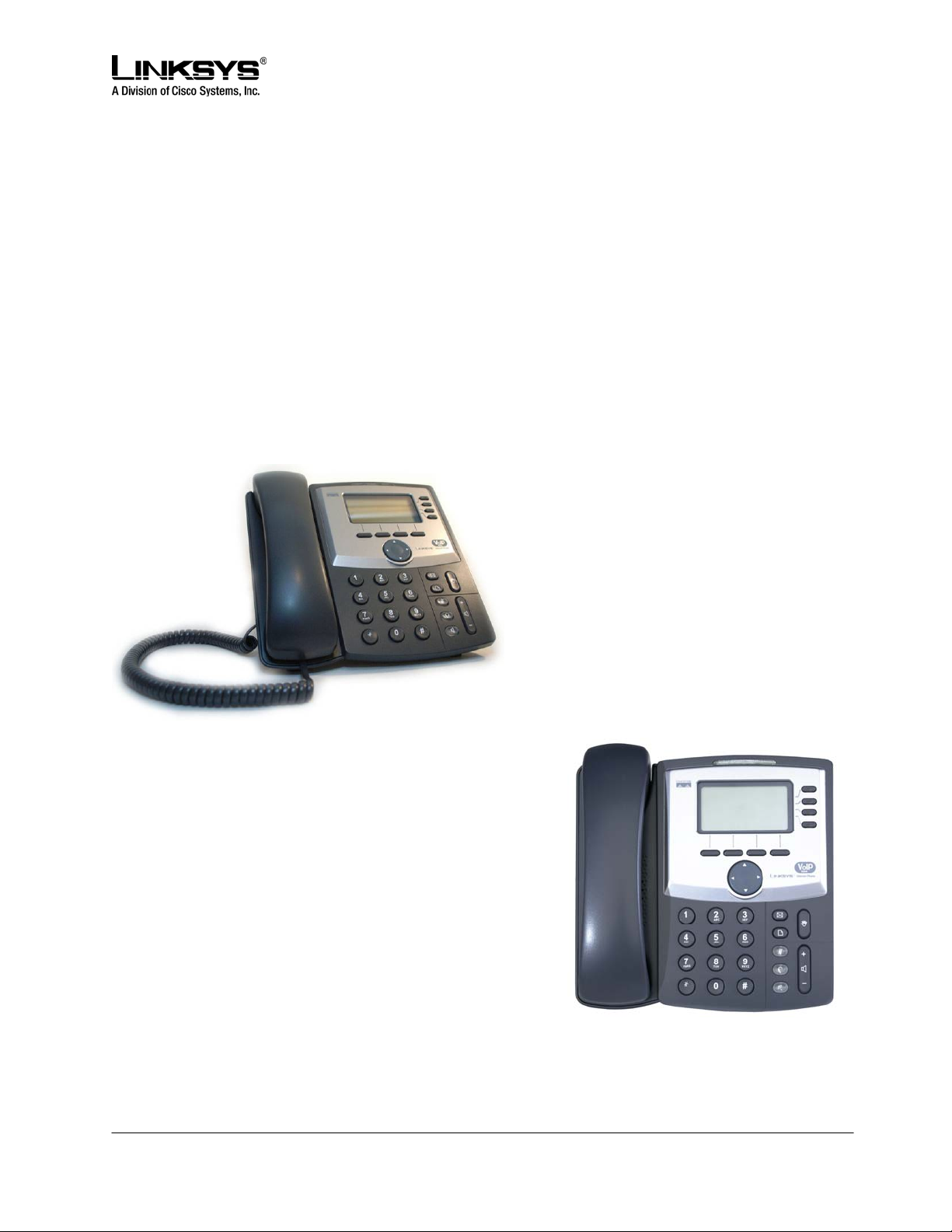
• SPA941 Overview
The SPA941 is a SIP based IP telephone offered by Linksys, a division of Cisco Systems. The SPA941
supports up to four phones lines of operation. It has a pixel-based display and a graphical user interface
that provides access to the phone’s functions and features. Figure 1.1 shows an illustration of the phone.
© 2003 - 2005 Linksys, a Division of Cisco Systems Proprietary (See Copyright Notice on Page 2)
10
Page 11
DRAFT
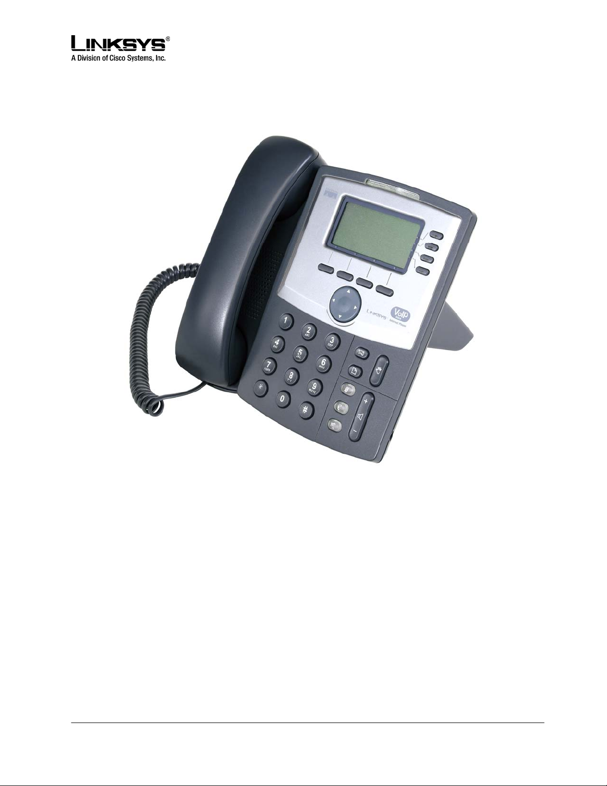
Figure 1.1: SPA941: Linksys IP Phone
SPA941 Hardware Features:
• Pixel Based Display: 128x64 Monochrome Graphical Liquid Crystal Display (LCD)
• Four Illuminated Call Appearance Line Buttons with Tricolor LEDs
o LED Indicates Line State – Active, Idle, On-Hold, Unregistered
o Line LED Configurable to 13 Different States (On/Off, Color, Flash)
• Dedicated Illuminated Buttons for:
o Audio Mute On/Off
o Headset On/Off
o Speakerphone On/Off
• Four Soft Key Buttons
• Four Way Rocking Direction Knob for Menu Navigation
© 2003 - 2005 Linksys, a Division of Cisco Systems Proprietary (See Copyright Notice on Page 2)
11
Page 12

DRAFT
• Voice Mail Message Waiting Indicator Light
• Voice Mail Message Retrieval Button
• Dedicated Call Hold Button
• Menu / Settings Button for Access to Feature, Set-up and Configuration Menus
• Volume Control Up/Down Rocking Knob Controls Handset, Headset, Speaker, Ringer
• Standard 12-Button Dialing Pad
• High Quality Handset and Cradle
• Built-In High Quality Microphone and Speaker
• Headset Jack – 2.5 millimeter
• Ethernet LAN – 10BaseT RJ-45
• Five volt DC Universal (100-240 Volt) Switching Power Adapter
• LED Test Function
SPA941 Features and Functions
• Up to Four Call Appearances with Independent Configuration and Registration
The SPA941 ships with two line appearances enabled. A two line upgrade is available via a
software license key installed locally using the SPA941 web interface, or installed remotely
via a secure profile update.
• Pixel Based Display: 128x64 Monochrome Graphical Liquid Crystal Display (LCD)
• Line Status - Active Line Indication, Name and Number
• Menu Driven User Interface
• Digits Dialed with Number Auto-Completion
• Shared Line Appearance **
• Full-Duplex Speakerphone
• Call Hold
• Music on Hold **
• Call Waiting
• Caller ID Name and Number
• Outbound Caller ID Blocking
• Call Transfer - Attended and Blind
• Call Conferencing
• Automatic Redial
• On-hook Dialing
• Call Pick Up - Selective and Group **
• Call Park and UnPark **
• Call Swap
• Call Back on Busy
• Call Blocking - Anonymous and Selective
• Call Forwarding - Unconditional, No Answer, On Busy
• Hot Line and Warm Line Automatic Calling
© 2003 - 2005 Linksys, a Division of Cisco Systems Proprietary (See Copyright Notice on Page 2)
12
Page 13

DRAFT
• Call Logs (60 entries each): Made, Answered, and Missed Calls
• Redial from Call Logs
• Personal Directory with Auto-dial (100 entries)
• Called Number with Directory Name Matching
• Call Number using Name - Directory Matching, Log Matching, or via Caller ID
• Subsequent Incoming Calls with Calling Name and Number
• URI (IP) Dialing Support (Vanity Numbers)
• Configurable Dial Plans with Auto-Completion of dialed number
• Do Not Disturb (callers hear line busy tone)
• On Hook Default Audio Configuration (Speakerphone and Headset)
• Multiple Ring Tones with Selectable Ring Tone per Extension
• Date and Time with Intelligent Daylight Savings Support
• Call Timer
• Call Duration and Start Time Stored in Call Logs
• Name and Identity (Text) Displayed at Start Up
• Distinctive Ringing Based on Calling and Called Number
• Ten User Downloadable Ring Tones - Ring Tone Generator Free from www.linksys.com
• Speed Dialing
• Configurable Dial/Numbering Plan Support - per Line
• DNS SRV and Multiple A Records for Proxy Lookup and Proxy Redundancy
• Syslog, Debug, Report Generation, and Event Logging
• SecureCall Encrypted Voice Communication Support
• Built-in Web Server for Administration and Configuration with Multiple Security Levels
• Automated Provisioning, Multiple Methods. Up to 256 Bit Encryption: (HTTP, HTTPS, TFTP)
• Optionally Require Admin Password to Reset Unit to factory Defaults
** Feature requires support by call server
Navigating the SPA941 Graphical User Interface
Note: Although this guide provides an overview of how to navigate the SPA941 Graphical User Interface
(GUI), its primary focus is to describe the administrative functions available via the phone’s web interface.
For more detailed discussion of the phone’s user interface, please refer to the SPA941 User Guide.
The user can invoke the phone’s GUI by pressing the menu button, and can navigate through the menus
using the round directional rocker knob and the soft keys. The menus are hierarchical. The select soft
key appears when a menu entry has a sub-menu. The sub-menu is entered by pressing the select soft
key, and exited by pressing the cancel soft key. The menus can be exited, and the phone returned to it
default display, by pressing the menu button.
The phone has four soft keys, but at times, more than four functions can be performed with the soft keys.
When this occurs, a small triangle appears at either the bottom right or the bottom left corner of the
display. This indicates that more soft key functions can be accessed by pushing the four way rocker knob
right or left respectively.
© 2003 - 2005 Linksys, a Division of Cisco Systems Proprietary (See Copyright Notice on Page 2)
13
Page 14

DRAFT
Up to four menu items can be displayed at one time. The entries in each menu can be cycled through in
a circular fashion by pressing the up and down arrows on the directional rocker knob. Pressing the down
arrow when the last entry in a menu is selected causes the cursor to move back to the top entry in the
menu list. Press the up arrow when the first menu entry is selected causes the cursor to move to the last
entry in menu.
While the user is navigating the menus down to a leaf level item, a number is displayed on the left side of
each menu entry that indicates its position in the current menu list. A menu item can be directly accessed
by typing its number on the keypad, even if the item isn’t currently visible on the display. For instance,
when the menu key is pressed to display the top level menus, items one through four are displayed. Item
nine can be immediately entered by pressing the 9 key on the keypad, without having to scroll down to
that item. Similarly, the fifteenth item in a menu can be entered by pressing the 1 key followed by the 5
key, with less than a two second pause between the key presses. Any leading 0 entries are ignored.
Some of the entries in the menus, such as those in the Status menu, are only informational; these entries
cannot be changed from within the menus. Typically only the cancel soft key is active when informational
menu entries are displayed.
The changeable menu entries can be modified by pressing the select soft key while the entry is
highlighted. The soft keys change to display the list of choices to modify the selected phone feature, such
as add, paste, edit, and delete. The modified entry can be saved by pressing the save soft key, or
discarded by pressing the cancel soft key.
A menu item’s display string may be wider than what can be displayed. When the user highlights a wide
item, the SPA941 automatically scrolls the contents horizontally from right to left so that the user can view
the entire text string.
Definitions for the Four Call Appearances
Some definitions:
• Station: A SPA941 phone (or a similar device in the Linksys SPA family) with one or more
Extensions and Call appearances provisioned
• Ext: An extension in the SPA941 is a VoIP account in a voice service provider (VSP)’s network or
an IP-PBX system. An extension can be uniquely identified with a User ID (like a phone number)
that is unique within the VSP. Up to 4 extensions can be configured in the SPA941, which are
refered to as Ext 1, Ext 2, Ext 3, and Ext 4 (or simply E1, E2, E3, and E4 respectively). Note that
the same extension can be configured on more than one station. These extensions are called
Shared Extensions. Extension 1 is referred to as the Primary Extension. Some features can only
be activated on the Primary Extension, such as Call Forwarding and Voice Mail Waiting Indicator
(VMWI).
• Call Appearance: Physically a call appearance corresponds to a Line Key on a station. There are
four Line Keys on the SPA941, which are referred to as Line Keys 1, 2, 3, and 4, or, L1, L2, L3,
and L4 respectively). Functionally, a call appearance is an instance of an extension. If an
extension is assigned to Line Keys on multiple stations, it is a Shared Line Appearance. One
© 2003 - 2005 Linksys, a Division of Cisco Systems Proprietary (See Copyright Notice on Page 2)
14
Page 15

DRAFT
extension can be assigned to multiple Line Keys on a SPA941. In fact, all four call appearances
can be instances of the same extension. (This extension is not a Shared Line Appearance
unless it is also assigned to a Line Key on another station.) Any of the four Line Keys can be
disabled. Each call appearance supports one call at a time, either active or on hold.
• VoIP Interface (VI): An Extension and its associated control parameters configured on a particular
station. The SPA941 includes a rich set of configuration parameters to control the operation
when calling via the account. Configuring an extension on the SPA941 includes configuring the
core account information and the set of VI control parameters. While the account information is
usually the same for a shared extension on different stations, the rest of the VI parameters can be
different. For example, the dial plan or the preferred codec to use when making a call on this
extension could be different for two different stations sharing the extension.
• Call Appearance State (CAST): The state of a call appearance which can be one of the following:
o Disabled: The Line Key is disabled
o Idle (Ready): The Call Appearance is ready for use
o Dialing: Collecting digits from the user to be dialed out from this Line
o Calling: Waiting for the called party to respond
o Proceeding (a.k.a. Progressing): Called party’s station is ringing
o Ringing (a.k.a. Alerting): Incoming call, station is ringing
o Connected: Connected with remote party
o Held: Remote party is on hold
o Invalid: Remote party hangs up or error while attempting outbound call
o Busy: the line is being used by another station (shared line only)
• Call State: A Call Appearance State followed by the term “Call”. For example, a Ringing Call, a
Dialing Call
• Active (Call) State: If the state is Dialing, Calling, Proceeding, Connected, or Invalid. When the
state of the Call is Active, it is referred to as an Active Call
• Standby (Call) State: the state is Ringing or Holding. When the state of the Call is Standby, it is
referred to as a Standby Call
• Key: Any one of the keys on the SPA941 keypad. A Key has two states: down (when pressed),
and up (when released)
• Button – a Key with an on and off state. The on/off state toggles when the key is pressed down
where applicable. There are 3 buttons on the SPA941: SPEAKER, HEADSET, and MUTE. Each
button has an associated LED that indicates the on/off state.
• SK(label) – Soft key with the given label, such as SK(select), SK(cancel), SK(dial), SK(conf),
SK(xfer)
• Call Features
Selecting Audio I/O Device and Line
There are three sets of audio I/O devices available: a) Handset, b) Built-in microphone and speaker, and
c) External microphone and headset. The speaker is also used for ri nging. For convenience, where the
context is clear, these are referred to as (b) the speaker, and (c) the headset.
© 2003 - 2005 Linksys, a Division of Cisco Systems Proprietary (See Copyright Notice on Page 2)
15
Page 16

DRAFT
Only one audio device can be selected at anytime. The speaker is selected by pressing the SPEAKER
button. The headset is selected by pressing the HEADSET button. When the SPEAKER or HEADSET is
selected, the corresponding LED will be steady GREEN. The handset is selected whenever it goes from
the on-hook to the off-hook position. Hence selecting or turning on of any of the audio device is equivalent
to an off-hook action, while turning off of any of the audio devices while it is equivalent to an on-hook
(hang-up) operation.
When there are no active calls, all audio devices are deselected. When any one of the calls becomes
active, the handset will be selected automatically as the audio device if it is off-hook, else the speaker or
the headset will be selected according to configuration: the user can configure whether speaker or the
headset device has higher preference.
A line is selected by pressing the corresponding Line Key.
To make or receive calls, the user must select a call appearance (Line Key) or an audio device. If the
user selects a call appearance, then an audio device is selected automatically according to user’ s
preference setting. If the user selects an audio device, an idle call appea rance is selected automatically
in the order L1, L2, L3, and L4. The user may switch between audio devices while the call in any of the
active states.
Exception: When a new call appearance is selected automatically when the user presses the conf soft
key or the xfer soft key, the SPA941 will attempt to pick an idle call appearance that is on the same
Extension as the last active call. If that call appearance is not available, the SPA941 attempts to pick one
whose Extension has the same Proxy server as the last active call. Finally, if that fails, the first idle call
appearance is selected, in the order L1, L2, L3, L4.
Making Calls
There are two steps in making a call:
1) Select an audio device, and
2) Dial the number.
The SPA941 allows the user to perform these two steps in either order. In other words, the user can
select an audio device either before or after dialing.
The SPA941 supports two types of dialing: explicit or implicit. Explicit dialing refers to one of the following
cases:
• enter the target number digits one by one
• enter the speed dial assignment of the target number
• select an entry from a directory, and press the dial soft key
• press a dedicated key, such as the Voice Mail key
“Implicit dialing” refers to dialing a highlighted entry from one of the device’s directories or logs. A number
can be implicitly dialing by selecting an audio device while the number is highlighted on the display.
© 2003 - 2005 Linksys, a Division of Cisco Systems Proprietary (See Copyright Notice on Page 2)
16
Page 17

DRAFT
If an audio device is selected prior to dialing, then only explicit dialing is supported. Both explicit and
implicit dialing are allowed if the audio device is selected after dialing. Explicit dialing before the audio
device is selected is called “on-hook dialing”.
When an audio device is selected before dialing, a call appearance (for making the call) is also indirectly
selected. The SPA941 will pick the first available call appearance, in descending order, starting with Line
Key One. If no call appearances are available, no audio devices are selected.
A call appearance can be explicitly selected by pressing the corresponding line key. An audio device is
selected automatically based on the device’s programmed preferences. (Set by pressing menu Æ
Preferences Æ Preferred Audio Device, or by accessing the User tab of the web based interface.
Answering Calls
A line key LED rapidly blinks red when a call is incoming. The user can answer the call by:
• Selecting an audio device.
The SPA941 will answer the ringing call. If there are simultaneous incoming calls, the call ringing on
the lowest numbered line key is answered.
• Pressing the corresponding Line Key. The default audio device will be automatically selected.
Ending Calls
When a call is in the active state (not on hold or parked), the call can be ended by turning off the currently
selected audio device. A call in a standby state cannot be ended; it must be brought back to the active
state first.
Hold and Resume
An active call can be placed on hold by
• explicitly pressing the Hold key, or by
• pressing another Line Key (to answer an incoming all, resume a held call, or start a new call).
When a call is on hold, the corresponding Line Key LED slowly blinks red. To resume a call that is on
hold, press the corresponding Line Key.
When the phone is hosting a three way conference, two call appearances are in the connected state.
Pressing the Hold key places both calls on hold. The calls can be individually brought back to the
connected state by pressing the corresponding Line Keys.
Call Waiting
The Call Waiting function is activated when a device has a call in the active state and another call is
incoming. The phones in the SPA series do not support multiple calls on the same Line Key. Incoming
calls are assigned to an unused Line Key, causing the Line Key to quickly blink red. (Note that the Voice
Mail Waiting Indicator also blinks red whenever there is an incoming call.) The phone will not ring.
However, to alert the user, the call waiting tone is played into the active audio device.
© 2003 - 2005 Linksys, a Division of Cisco Systems Proprietary (See Copyright Notice on Page 2)
17
Page 18

DRAFT
The SPA941 allow multiple lines to simultaneously cause Call Waiting. All four call appearances can ring
at the same time, after one of the Extension Keys is answered, the other three call appearances will go
into the Call Waiting state.
Three Way Conferencing
There are two ways to initiate a three way conference on the SPA941:
• During an active call, if the phone has one or more idle call appearances, press the conf soft key.
This places the active call on hold and selects the next available call appearance for dialing (the dial
tone is heard in the active audio device). Dial the third party, the party to be added to the conference
call. After the third party’s line rings or is answered, presses the conf soft key again to join the two
calls into a conference.
• If the phone has a call is on hold while another call is either ringing or is connected, the confLx soft
key appears. If the phone has only one call on hold, pressing the confLx soft key joins the call on
hold with the active call. If the phone has more than one call on hold, pressing the confLx soft key
places the active call on hold and prompts the user to select the other Line Key to join with the
conference call.
Once the conference starts, the SPA941 plays a special brief tone to all three parties to indicate that a
conference call is in progress. The initiator of the conference call can terminate it at any time by hanging
up. The initiator leave the conference without ending the call by pressing join soft key; this allows the
other two parties to continue the call. This is implemented as a call transfer, which may not work if the
other two parties are hosted by different service providers.
Note: If the extension is configured with an external Conference Bridge URL, then conference is not
limited to three way; it can be as many parties as the conference bridge supports. There are two
restrictions that apply when using an external conference bridge:
1) The conference can only be initiated (by pressing the conf soft key) when the third party has
answered, instead of when the phone is either ringing or answered, and
2) Ringing call cannot be brought into a conference by pressing the confLx soft key; only calls that
are on hold can be brought into the conference with the confLx soft key.
Attended Call Transfer
An attended call transfer allows a user to optionally transfer a call to a third party, after having a
discussion with that third party. There are two ways to perform an attended call transfer:
• During an active call, press the xfer soft key to place the current call on hold and to activate an idle
Line Key. Dialed the transfer target number on the newly activated line. When the target is either
ringing or answered, press the xfer soft key again to complete the transfer.
• While one or more call appearances is on hold, initiate a call on an idle Line Key. While the call is
either ringing or is connected, press the xferLx line key. If only one other call is on hold, the active
© 2003 - 2005 Linksys, a Division of Cisco Systems Proprietary (See Copyright Notice on Page 2)
18
Page 19

DRAFT
call is connected with the call on hold. Otherwise, the user is prompted to select which Line Key to
transfer the call to.
Notes:
• At the completion of call transfer operation, the holding call peer will be the transferee, and the
connected or proceeding call peer will be the transfer target.
• The case where a call transfer is completed when the transfer target is ringi ng is called a semi-
attended call transfer. This is different from a blind transfer which is described in the next subsection.
Blind Call Transfer
A blind transfer allows the user to transfer a call without speaking with the receiver of the transferred call.
For the user, the call ends as soon as the transfer target’s phone number is dialed. The underlying
mechanism is the user’s phone sends the contact information for the transfer target to the phone of the
other party on the call. The information is carried in a signaling message. When the message is sent, the
user’s phone is dropped from the call and the other party’s phone automatically dials the transfer target.
To perform a blind transfer press the bxfer soft key and then dial the target number. The bxfer soft key
will automatically become active during a call, but it may not be visible on the display. If the bxfer key is
not visible, press the left / right direction arrows on the directional rocker know until it scrolls onto the
display.
Some older SPA phones do not have bxfer soft keys. To perform a blind transfer on these older devices,
during the call, press the xfer soft key, or the Line Key of an unused line. (There must be a spare line
available to perform the transfer.) Once the new dial tone is heard, enter *98; the phone will prompt the
user to enter the phone number of the transfer target. Enter the number to complete the blind transfer. If
the user’s phone has more than one call on-hold on, the last call placed on hold will be the on e
transferred.
Call Back
This service mimics the call back service offered by the PSTN. The user can activate this service on a
busy number such that he will be called back as soon as the busy number becomes available. The
SPA941 (and other members in the SPA family) implements this feature by repeatedly dialing the busy
number periodically until the called party rings or answers, or until the service order is canceled by the
user or expires. For that reason, it is better referred to as the repeat dialing service.
To activate this service, the user selects a Line key and enters *66 (Call back activation code). The
SPA941 then uses this call appearance to call the last called number. The retry period and expiration time
are configurable. To cancel the service, the user picks up any line and enter *86. When call back service
is active, the corresponding Line key will blink in green. The user can still use this line to make or answer
calls; when that happens the call back service is temporarily paused until the call appearance is idle
again.
© 2003 - 2005 Linksys, a Division of Cisco Systems Proprietary (See Copyright Notice on Page 2)
19
Page 20

DRAFT
When the call back number rings or answers, the call appearance will ring also like a normal incoming call
(the ring to be used is the default ring for the corresponding extension for that Line key). If the call back
party answers the call before the local user does, the SPA941 sends holding tone to the call back party. If
the local user picks up the call back Line key first, he will hear ring back tone like a regular outbound call.
Message Waiting Indication (MWI)
The SPA941 indicates message waiting in 2 ways:
1. Turning on the red MWI light - LED (with an envelope icon right above LED) on the phone.
2. Playing stutter tone instead of regular dial tone. The MWI light only applies to new message
indication received on Extension 1. It will not be turned on or off due to new message indication
received on the other Extensions [2 – 4]. On the other hand, the SPA941 can be configured to play a
stutter tone on the individual call appearance according to the message waiting state of the
corresponding Extension “X”.
Accessing Voice Mail
The SPA941 has a VM retrieval key for quick access to voice mail. If a voice mail access number or URL
is not specified, pressing the key brings up a screen where the user can enter the appropriate
information. This information can also be entered from the web page or downloaded via provisioning.
The SPA941 will attempt to call the voice mail number or URL if there is an idle call appearance available.
Muting Calls
The user can mute the audio input into the phone when an audio device is switched on, by pressing the
MUTE key. To un-mute, press the MUTE key again. If no audio device is on, pressing the MUTE key has
no effect. When switching from the speaker phone to the handset, the phone is automatically un-muted.
Shared Call Appearances
The SPA941 supports shared call appearances in association with a Broadsoft a pplication server. An
extension can be shared by two (2) or more stations. Any call appearances on a shared extension is a
shared call appearance. At any given time, each station sharing a call appearance can monitor the state
of the call appearance. A station can select a share call appearance to make a call only if the call
appearance is not being used by another station. All stations will ring on an inbound call to the shared
call appearance extension. Whoever picks up the call first will take the call. When a call is placed on
hold by one station, it can be resumed from another station sharing the same call appearance.
Additional methods for shared call appearances per vendor application server implementation are being
added to the SPA941 and will be available in future firmware releases. Please contact sales@linksys.com
to inquire about roadmap / development schedules.
© 2003 - 2005 Linksys, a Division of Cisco Systems Proprietary (See Copyright Notice on Page 2)
20
Page 21

DRAFT
Line Key LED Behavior
The following outlines the Line Key LED Behavior:
• A Line Key corresponds to a call appearance. Call appearances for the same extension are
numbered in ascending order of their Line Key position starting at 1. The Line Key LED color and
blinking pattern are fully programmable. The administrator can specify a different color and
pattern for each well-defined states of the call appearance. These states are described below.
• Idle: This call appearance is not in use. The user can use it to make outbound call on this station
• Local Seized: This call appearance has been seized by this station to prepare for an outbound
call
• Local Progressing: This station is making an outbound call that is progressing
• Local Active: This station is engaged in a connected call on this call appearance
• Local Ringing: This station is ringing for an incoming call on this call appearance
• Local Held: This station has placed this call appearance on hold
• Remote Seized: This call appearance has been seized by another station to prepare for an
outbound call
• Remote Progressing: Another station is making a call on this call appearance and is progressing
• Remote Active: Another station is engaged in a connected call on this call appearance
• Remote Ringing: Another station is ringing for an incoming call to this call appearance
• Remote Held: Another station has placed this call appearance on hold
• Remote Undefined: The share call state is not known (this station is waiting for a notification from
the application server)
• Registration Failed: This station has failed to register with the proxy server for the corresponding
extension
• Registering: The station is attempting registration with the proxy server for the corresponding
extension.
• Disabled: This Line Key on this station is disabled
• Call Back: A call back (repeat dialing) operation is currently active on this call appearance
The Line Key LED supports 4 colors: Red (r), Green (g), Amber (a), and Off (o). The SPA941 has 4 builtin blinking patterns defined:
• No Blink (nb): Steady on (or off)
• Slow Blink (sb): 500ms on, 500ms off
• Fast Blink (fb): 100ms on, 100ms off
• Double Blink (db): 100ms on, 100ms off, 100ms on, 700ms off
The administrator can also define arbitrary blinking pattern by following the syntax of a LedScript. The
default LedScript for each call appearance state is described in section 3.
© 2003 - 2005 Linksys, a Division of Cisco Systems Proprietary (See Copyright Notice on Page 2)
21
Page 22

DRAFT
Other Supplementary Services
The SPA941 supports the following supplementary Services:
Block Caller ID
If enabled, the SPA941 will attempt to hide the caller-ID on all outbound calls by default. The user can
also enable or disable this feature on a per call basis by pre dialing a *code befo re making the call.
Block Anonymous Call
Reject all inbound calls with no caller-ID with a 406 response
Do Not Disturb (DND)
Reject all inbound calls as if the phone is busy. That is, the phone either responds a 302 if call forward on
busy if enabled, or 486 otherwise.
Secure Call
If enabled, the SPA941 will try to negotiate on all outbound calls to use encrypted media (SRTP) by
default. The user can also enable or disable this feature on a per call basis by pre dialing a *code before
making the call. Note that in order to use Secure Call on an extension, <Mini Certificate> and <SRTP
Private Key> must be configured for that extension.
The enabling and disabling of these services applies to calls on all configured extensions on the SPA941
Secure Call Implementation:
A secure call is established in two stages. The first stage is no different form a normal call setup. Right
after the call is established in the normal way with both sides ready to stream RTP packets, the second
stage starts where the two parties exchange information to determine if the current call can switch over to
the secure mode. The information is transported by base64 encoding and embedding in the message
body of SIP INFO requests and responses with a proprietary format. If the second stage is successful, the
SPA will play a special “Secure Call Indication Tone” for short while to indicate to both parties that the call
is secured and that RTP traffic in both directions are encrypted. The phone screen will be updated with
the CID information extracted from the Mini-Certificate received from the other end. The call state label on
the phone screen will also be prepended with a ‘$’ symbol (such as $Connected instead of Connected).
The second stage in setting up a secure all can be further divided into two steps. Step 1 the caller sends
a “Caller Hello” message (base64 encoded and embedded in the message body of a SIP INFO request)
to the called party with the following information:
- Message ID (4B)
- Version and flags (4B)
© 2003 - 2005 Linksys, a Division of Cisco Systems Proprietary (See Copyright Notice on Page 2)
22
Page 23

DRAFT
- SSRC of the encrypted stream (4B)
- Mini-Certificate (252B)
Upon receiving the Caller Hello, the callee responds with a Callee Hello message (base64 encoded and
embedded in the message body of a SIP response to the caller’s INFO request) with similar information, if
the Caller Hello message is valid. The caller then examines the Callee Hello and proceeds to step 2 if the
message is valid. In step 2 the caller sends the “Caller Final” message to the callee with the following
information:
- Message ID (4B)
- Encrypted Master Key (16B or 128b)
- Encrypted Master Salt (16B or 128b)
With the master key and master salt encrypted with the public key from the callee’s mini-certificate. The
master key and master salt are used by both ends for the derivation of session keys for encrypting
subsequent RTP packets. The callee then responds with a Callee Final message (which is an empty
message).
A Mini-Certificate contains the following information:
- User Name (32B)
- User ID or Phone Number (16B)
- Expiration Date (12B)
- Public Key (512b or 64B)
- Signature (1024b or 512B)
The signing agent is implicit and must be the same for all SPA’s that intended to communicate securely
with each other. The public key of the signing agent is pre-configured into the SPA’s by the administrator
and will be used by the SPA to verify the Mini-Certificate of its peer. The Mini-Certificate is valid if a) it has
not expired, and b) its signature checks out.
User Interface
The SPA can be set up such that all outbound calls are secure calls by default, or not secure by default. If
outbound calls are secure by default, user has the option to disable security when making the next call by
dialing *19 before dialing the target number. If outbound calls are not secure by default, user has the
option to make the next outbound call secure by dialing *18 before dialing the target number. On the other
hand, user cannot force inbound calls to be secure or not secure; it is at the mercy of the caller whether
he/she enables security or not for that call.
If the call successfully switches to the secure mode, both parties will hear the “Secure Call Indication
Tone” for a short while and the CID will be updated with the Name and Number extracted from the MiniCertificate sent by the other partyThe callee should check the name and number again to ensure the
identity of the caller. The caller should also double check the name and number of the callee to make
sure this is what he/she expects. Note that the SPA will not switch to secure mode if the callee’s CID
Number from its Mini-Certificate does not agree with the user-id used in making the outbound call: the
caller’s SPA will perform this check after receiving the callee’s Mini-Certificate.
© 2003 - 2005 Linksys, a Division of Cisco Systems Proprietary (See Copyright Notice on Page 2)
23
Page 24

DRAFT
Service Provider Requirements
The SPA Mini-Certificate (MC) has a 512-bit public key used for establishing secure calls. The
administrator must provision each subscriber of the secure call service with an MC and the corresponding
512-bit private key. The MC is signed with a 1024-bit private key of the service provider who acts as the
CA of the MC. The 1024-bit public key of the CA signing the MC must also be provisioned to each
subscriber. The CA public key is used by the SPA to verify the MC received from the other end. If the MC
is invalid, the SPA will not switch to secure mode. The MC and the 1024-bit CA public key are
concatenated and base64 encoded into the single parameter <Mini Certificate>. The 512-bit private key is
base64 encoded into the <SRTP Private Key> parameter, which should be hidden from the SPA’s web
interface like a password.
Since the secure call establishment relies on exchange of information embedded in message bodies of
SIP INFO requests/responses, the service provider must maker sure that their infrastructure will allow the
SIP INFO messages to pass through with the message body unmodified.
Linksys provides a configuration tool called gen_mc for the generation of MC and private keys with the
following syntax:
gen_mc <ca-key> <user-name> <user-id> <expire-date>
Where:
- ca-key is a text file with the base64 encoded 1024-bit CA private/public key pairs for signing/verifying
the MC, such as
9CC9aYU1X5lJuU+EBZmi3AmcqE9U1LxEOGwopaGyGOh3VyhKgi6JaVtQZt87PiJINKW8XQj3B9Qqe3V
gYxWCQNa335YCnDsenASeBxuMIEaBCYd1l1fVEodJZOGwXwfAde0MhcbD0kj7LVlzcsTyk2TZYTccnZ7
5TuTjj13qvYs=
5nEtOrkCa84/mEwl3D9tSvVLyliwQ+u/Hd+C8u5SNk7hsAUZaA9TqH8Iw0J/IqSrsf6scsmundY5j7Z5mK5J
9uBxSB8t8vamFGD0pF4zhNtbrVvIXKI9kmp4vph1C5jzO9gDfs3MF+zjyYrVUFdM+pXtDBxmM+fGUfrpAu
Xb7/k=
- user-name is the name of the subscriber, such as “Joe Smith”. Maximum length is 32 characters
- user-id is the user-id of the subscriber and must be exactly the same as the user-id used in the INVITE
when making the call, such as “14083331234”. Maximum length is 16 chara cters.
- expire-date is the expiration date of the MC, such as “00:00:00 1/1/34” (34=2034). Internally the date is
encoded as a fixed 12B string: 000000010134
The tool generates the <Mini Certificate> and <SRTP Private Key> parameters that can be provisioned to
the SPA.
For Example:
gen_mc ca_key “Joe Smith” 14085551234 “00:00:00 1/1/34”
Produces:
<Mini Certificate>
Sm9lIFNtaXRoAAAAAAAAAAAAAAAAAAAAAAAAAAAAAAAxNDA4NTU1MTIzNAAAAAAAMDAwMDAw
MDEwMTM00OvJakde2vVMF3Rw4pPXL7lAgIagMpbLSAG2+++YlSqt198Cp9rP/xMGFfoPmDKGx6JFtk
Q5sxLcuwgxpxpxkeXvpZKlYlpsb28L4Rhg5qZA+Gqj1hDFCmG6dffZ9SJhxES767G0JIS+N8lQBLr0Auem
© 2003 - 2005 Linksys, a Division of Cisco Systems Proprietary (See Copyright Notice on Page 2)
24
Page 25

DRAFT
otknSjjjOy8c+1lTCd2t44Mh0vmwNg4fDck2YdmTMBR516xJt4/uQ/LJQlni2kwqlm7scDvll5k232EvvvVtCK0
AYa4eWd6fQOpiESCO9CC9aYU1X5lJuU+EBZmi3AmcqE9U1LxEOGwopaGyGOh3VyhKgi6JaVtQZt87P
iJINKW8XQj3B9Qqe3VgYxWCQNa335YCnDsenASeBxuMIEaBCYd1l1fVEodJZOGwXwfAde0MhcbD0kj
7LVlzcsTyk2TZYTccnZ75TuTjj13qvYs=
<SRTP Private Key>
b/DWc96X4YQraCnYzl5en1CIUhVQQqrvcr6Qd/8R52IEvJjOw/e+Klm4XiiFEPaKmU8UbooxKG36SEdKus
p0AQ==
• Memory Features and other User Accessible Settings
Call Logs
There are three call logs maintained for each VoIP interface:
• Redial List – Each Redial List entry is added when dialing is completed, regardless the number is
correct or not, or the call is successful or not
• Answered Calls – An Answered Call is logged when the coming call is answered.
• Missed Calls – A Missed Call is logged for each incoming call that causes the phone to ring but
not answered.
From the Phone GUI, the user can:
View a call log:
1. Press SETUP
2. Select “Call History”
3. Select the log you want to view
Delete a log,
1. High light the entry
2. Press SK(del)
Edit a log,
1. High light the entry
2. Press SK(edit)
3. Press SK(save) to save the changes, or SK(cancel) to abort the changes
Call a log entry
1. High light the entry
2. Press SK(dial), or Off-Hook, or Turn on Speaker, or Turn on Headset, or Press a Line Key
Save a log entry into Personal Directory (if the directory is not already full)
1. High light the entry
2. Press SK(save)
3. Modify the entry as needed
© 2003 - 2005 Linksys, a Division of Cisco Systems Proprietary (See Copyright Notice on Page 2)
25
Page 26

DRAFT
4. Press SK(save) to save the entry in the personal directory
The SPA941 keeps up to 60 entries per log in reverse chronological order. The logs are saved in the
phone’s non-volatile memory.
All call logs can be viewed on the SPA941 web page also using the link:
http://<ip-address./calllog.htm
Each log is shown on the web page with the syntax: [ext-id]name, phone, time-stamp
• ext-id is the extension on which the call is made from or received at (E1, E2, E3, or E4). If [En] is
not present, it implies [E1].
• name is the call peer’s name. If this field is missing, the peer’s name is not available
• phone is the call peer’s phone number (user-id). If this field is missing, the peer’s phone num ber
is not available
• t is the time-stamp at which the call log is entered. It has the format mm/dd hh/mm<a|p> (where a
= am and p = pm
Example 1: [E2]Joe Smith,14089991234,t=10/12 11:12a
Example 2: 14089991234,10/12 01:12p
(On E1; name not available)
Personal Directory
A directory entry consists of the following information:
• Name
• Phone number or (SIP) URL
• Ring Tone
Up to 100 entries can be stored in the SPA941. An entry can be added or edited from the phone GUI or
on the web page or through remote provisioning. To do this from the web page or through remote
provisioning, you specify the value as a DirEntry script. To view or edit the personal directory via the
phone web interface, use the link
The user can invoke the Directory menu on the phone in 2 ways: a) Press the menu button and select
“Directory”, or b) Press SK(dir) when you’re not already in a SETUP screen. The user can add a new
entry to the Directory by selecting the “New Entry” option (the first item) on the Directory menu and press
SK(add). To modify or delete an existing item, highlight the corresponding entry and press SK(edit) or
SK(del). When trying to delete an entry, the phone will prompt the user for confirmation before
proceeding.
© 2003 - 2005 Linksys, a Division of Cisco Systems Proprietary (See Copyright Notice on Page 2)
http://<ip-address>/pdir.htm
26
Page 27

DRAFT
The user can copy an existing directory entry to create a new entry. To do this, high light the entry you
want to copy and press SK(copy). Then high light the “New Entry” option and press SK(paste). The user
can edit the new entry and then press SK(save) to save the entry.
The user can also save a call log entry into the directory. To do this, select a call log entry and press
SK(save). Then edit the entry if needed, and then press SK(save) to save the new entry in the directory.
Entering and Saving Settings
The SPA941 GUI allows the user to enter alphanumeric and numeric inputs will ease. The following data
types may be entered into the phone:
• Numeric String, such as a phone number when dialing
• Alphanumeric String, such a name when adding a Directory entry
• IP Address, such as a DNS server IP address
• Boolean (y/n), such as enabling or disabling DHCP
• Option, such as selecting a preferred audio device or a ring tone
When any two or more of the numeric string, alphanumeric string, and IP address types can apply to an
entry, the phone will show a soft key for switching input modes among the applicable types. The soft keys
will change when pressed to allow the user to scroll through the available modes, such as SK(num) Æ
SK(alpha) Æ SK(IP). The cursor will also change according to the following table, to remind the user
which input mode is being used:
Input Mode Soft Key Cursor (appending) Cursor (inserting)
Numeric num Blinking underscore _ Blinking vertical line |
Alphanumeric alpha
IP Address IP
When entering digits during numeric mode, just enter the corresponding digits from the key pad.
When entering letters or symbols during alphanumeric mode, the phone will show a template of 2 or more
choices of symbols as the user presses each digit key; the user can scroll through the choices by
pressing the same key multiple times. To accept a symbol as input, the user can a)stop pre s sing the digit
key for 1.5s, b)pressing another digit key, c)navigate to another input field (if applicable) by pressing the
UP/DOWN key, or d)save the value by pressing the proper soft key, such SK(save) or SK(ok)
When entering IP address, pressing the * digit will insert a dot (.), or a colon (:) if there are 3 dots entered
already.
When entering numeric, alphanumeric, or IP address values, the following additional soft keys will be
available for easier editing:
• SK(<<) – Move cursor to the left by 1 character
• SK(>>) – Move cursor to the right by 1 character
• SK(erase<) – Erase the character to the left of the cursor
Blinking full-height block █ Blinking open rectangle 匚
Blinking half-height block ▅ Blinking half rectangle Ⅼ
© 2003 - 2005 Linksys, a Division of Cisco Systems Proprietary (See Copyright Notice on Page 2)
27
Page 28

DRAFT
• SK(clear) – Clear the entire entry
Note that SK(<<), SK(>>), SK(erase<), and the digit key presses will automatically repeat by keep
pressing the corresponding key down without releasing it. If input value is wider than what the LCD
display can show, the SPA941 automatically scroll the input to the left so that the user can continue to
enter input. On the other hand, the SPA941 will stop accepting further input for a give field if the
maximum allowed input length has been reached for that input field.
For Boolean input, the SPA941 will show SK(y/n) pressing which will toggle the current input between yes
and no.
For Option input, the SPA941 will show SK(option) pressing which will either a) change the input field to
the next available choice in round-robin fashion, or b) bring up a menu of choices that the user can select
from.
For most settings, the input value is saved once the user press SK(save) or SK(ok) before exiting the edit
screen for that setting. However, there are a few exceptions where the user must press SK(save) again at
the upper level when all the required changes have been made to the settings so that they are saved into
the configuration at the same time. These exceptions are:
Preferences
• Call Forward
• Network
Speed Dialing
The SPA941 has eight programmable speed dial numbers which can be set either through the GUI, or
through the User tab of the phone’s web page. To use the GUI to configure the speed dial, select the
Speed Dial entry after pressing menu key. The speed dial numbers are assigned to the digits two
through nine. If a slot is not configured, it will show <Not Assigned> on the entry. Highlight the speed dial
entry you want to add or modify, press SK(edit) to make the changes, and press SK(ok) to store the
value.
A speed dial entry can be a phone number or URL. The user can also enter a name that matches one of
the directory entries. As you enter the value, the SPA941 will attempt to match the entry to the directory
entries and brings up a list of potential matches on the screen. User can scroll down to select one of the
suggested entries.
To dial a speed dial, dial the corresponding single digit like a 1-digit phone number. The user can enter
“#” after the speed dial number but it is not necessary.
© 2003 - 2005 Linksys, a Division of Cisco Systems Proprietary (See Copyright Notice on Page 2)
28
Page 29

DRAFT
Caller and Called Name Matching
When making an outgoing call, SPA941 will try to find the dialed number in the personal directory first,
and then from the missed call log, and finally from the answered call log. If a match is found and the
name field is present in the matched entry, it will be shown on the call screen as the called peer’s name.
For incoming calls, SPA941 will try to find the caller’s phone number in the personal directory. If a match
is found and the name field is present in the matched entry, it will replace the current caller ID name and
will be shown on the call screen as the calling peer’s name. The same name will also go into the incoming
call log. If a match is not found, or the name field is not present in the matched entry, the current caller ID
name will be used if it exists.
Dialing Assistance
Dialing assistance is an option the user can enable or disable under the Preferences menu. If the option
is enabled, the phone will show up to ten potential matches from the Redial List (most recent first) and
from the Personal Directory as the user dials the target number. This feature applies to both off-hook
(with dial tone) and on-hook (without dial tone) dialing. When the suggestion list appears, the user can
scroll down the list using the Up/Down key to select the desired target number from the list.
When looking for matches from the Redial List and the Directory, the SPA941 will skip any leading
*codes, so that the match is purely based on the target number. The *code that will be skipped are (if
configured in the phone):
• All call forward activation and deactivation codes
• Secure call activation and deactivation codes
• Block CID activation and deactivation codes
• Block anonymous call activation and deactivation codes
• DND activation and deactivation codes
• All the Prefer codec and Force codec codes
• Referral services codes and Feature Dial Services codes
Time/Date
The SPA941 obtains the current time information from one of the following ways:
• NTP Server – One or two NTP servers can be configured to the phone. When it first boots up, the
phone will try to contact the NTP server to get the current time. Then the phone periodically
synchronizes the current time with the NTP server. The synchronization period is fixed at 1 hour.
In between the update, the phone tracks the time with its own internal clock.
• SIP Messages – Each SIP message (request or response) sent to the SPA may contain a Date
header with the current time information. If the header is present, the SPA will use it to update its
current time.
• Manual Setup – SPA941 also allows the user to manually enter the current time and date from
the phone GUI or from the web page. However, this value will be overridden by the NTP time or
© 2003 - 2005 Linksys, a Division of Cisco Systems Proprietary (See Copyright Notice on Page 2)
29
Page 30

DRAFT
SIP Message Date whenever they are presented to the phone. Manual setup requires the user to
enter the time in 24 hour format only.
Note that the time served by the NTP Server and the SIP Date Header are GMT time. The local time is
obtained by offsetting the GMT according to the time zone of the region. <Time Zone> can be configured
from the web page or provisioning. This time can be further offset by <Time Offset (HH/mm)> parameter,
which must be entered in 24 hour format only. This parameter can be configured from the Phone GUI
also.
The <Time Zone> and <Time Offset (HH/mm)> offset values are not applied to the manual time/date
setup.
Daylight Saving Time
The SPA941 supports auto adjustment for daylight saving time. To enable this feature, the administrator
must configure the <Daylight Saving Time Rule> (regional) parameter. This parameter is a rule with three
(3) fields. Each field is separated by semicolon (;) as shown below:
start=<start-time>;end=<end-time>;save=<save-time>
where
<start-time> and <end-time> are of the form: <month>/<day>/<weekday>[/HH:[mm[:ss]]]
<save-time> is of form: [/[+|-]HH:[mm[:ss]]]
<month> = 1,2,3,…,12 (for Jan, Feb, …, Dec)
<day> = [+|-]1,2,3,…,31
<weedday> = 1, 2, 3, …, 7 (for Mon, Tue, …, Sun), or 0 which has special meaning
HH = hour (0-23)
mm = minute (0-59)
ss = second (0-59)
<start-time> and <end-time> specify the start and end time-date of daylight saving time and <save-time>
is the amount of hour/min/sec to add to the current time during daylight saving period. The <save-time>
value can be preceded by a negative (-) sign if subtraction is desired instead of addition.
If <weekday> is 0, it means the date to start or end daylight saving is at exactly the given date. In that
case, the <day> value must not be negative. If <weekday> is not zero, then the daylight saving starts or
ends on the <weekday> on or after the given date if <day> is positive, or on or before the given date if
<day> is negative. If <day> is –1, it means the <weekday> on or before the end-of-the-month (in other
words the last occurrence of < weekday> in that month).
© 2003 - 2005 Linksys, a Division of Cisco Systems Proprietary (See Copyright Notice on Page 2)
30
Page 31

DRAFT
Optional values inside [ ] are assumed to be 0 if they are not specified. Midnight means 0:0:0 of the given
date.
Example 1:
Starts at midnight on 1st Sunday of April; ends at midnight on the last Sunday of October; add 1 hour
(USA, N. America). Below are all equivalent rules:
start=4/1/7/0:0:0;end=10/31/7/0:0:0;save=1
start=4/1/7;end=10/-1/7;save=1
start=4/1/7/0;end=10/-1/7/0;save=1
Example 2:
Starts at midnight on last Sunday of April; ends at midnight on the last Sunday of September; add 1 hour
(Egypt):
start=4/-1/5;end=9/-1/4;save=1 (Egypt)
Example 3:
Starts at midnight on first Sunday of October; ends at midnight on the 3rd Sunday of March; add 1 hour
(New Zealand):
start=10/1/7;3/22/7;save=1 (New Zealand)
Checking Phone Status
Besides the Info group on the web page, the Phone GUI has a Status menu where one can check the
current status of the phone.
Reboot and Restart
Reboot will cold boot the phone and restart DHCP. Restart will warm boot the phone, without restarting
DHCP. Both options require the user to confirm before proceeding.
Factory Reset
Factory reset will reset all parameters to default value. Personal directory and call logs will be cleared
also. This option require the user to confirm before proceeding.
© 2003 - 2005 Linksys, a Division of Cisco Systems Proprietary (See Copyright Notice on Page 2)
31
Page 32

DRAFT
Password Protection
The user can configure a password to the phone to protect against access to the following options:
• Directory
• Call History (Redial List, Missed Calls, and Answered Calls)
• Call Forward
• Speed Dial
• Ring Tone
• Preferences
• Time/Date
• Voice Mail
• Factory Reset
• Set Password
Audio Volume Adjustment
There are 4 kinds of audio volume to be adjusted:
• Ringer Volume (on the speaker)
• Speaker
• Handset
• Headset
To adjust the volume, press the VOL key to invoke the volume adjustment screen. Then use the
UP/DOWN keys to increase or decrease the volume. The kind of volume to adjust is by context. When no
audio device is selected at the moment, the Ringer volume will be adjusted. Each UP/DOWN key press
will play a short burst of the current ring tone. If one of the audio devices is selected, then the volume
adjustment applies to that device. The screen will show why kind of volume is being adjusted with a
pictorial representation of the volume level.
Each volume has 16 steps in nonlinear logarithmic scale. Each setting is a 16-bit multiplier in the range
41 to 32764 in Q3.12 format (or 0.01 to 7.999 or –40 to 18 dB). Each step is equal to 58/(16-1) or 3.87
dB.
Additional volume settings can be added and accessed via the phone setup screens. These volumes are:
• DTMF Echo Volume (use <DTMF Playback Level>)
• Call Progress Tone Volume (setting the ToneScript for each tone)
Ring Tone
The SPA941 offers 10 ring tones. The characteristics of each ring tone is configurable using a RingScript
(see Section 3). In a RingTone script, the user can assign a name for the ring tone, and specifies 2
components for it:
© 2003 - 2005 Linksys, a Division of Cisco Systems Proprietary (See Copyright Notice on Page 2)
32
Page 33

DRAFT
• Waveform – 1, 2, 3, or 4
• Cadence – 1, 2, 3, …, or 8
The user can assign a default ring tone for each extension. The user can assign a ring tone for each
personal directory entry (which overrides the default ring tone). Ring tone can be selected from the GUI.
In addition, the SPA941 allows 2 user-downloadable ring tones. Therefore a total of 12 ring tone choices
are available to the user to be used as default ring for an extension or assigned to individual callers in the
personal directory. The user downloaded ring tone as labeled as "User 1" and "User 2" in the choices for
the <Default Ring>. On the phone ring tone menu, the User 1 and 2 choices are replaced by the
corresponding name of the ring tone or “Not Installed” if the user ring tone slots have not been
downloaded into.
The user ring tone (1 or 2) can be downloaded using the phone web interface with the link:
http://<phone-ip-addr>/ringtone1[?<url>]
where <url> syntax is [tftp://][host[:port]]/<path>. Only tftp is supported. If host is not specified, the TFTP
host is the web client; default port is 69.To remove user ringtone 1 from the phone, set the <path> to
"delete", such as:
http://<phone-ip-addr>/ringtone1?/delete
The link is case sensitive.
Notes:
• For User Ring Tone 1 and 2, the cadence is fixed with the on-time equals to the duration of the ring
tone file and off-time equals to 4s. The total ring duration is fixed at 60s.
• The user ring tone names displayed on the phone GUI are extracted from the ring tone file header file
• No need to reboot phone after a ring tone download.
• However, if your phone is already in ring tone GUI menu while the new ring tone is downloaded, you
will need to exit and re-enter the ring tone menu in order to see the new ring tone name on the menu.
Star Code to Activate/Deactivate Certain Services
THE SPA941 accepts star codes to activate or deactivate certain services on the phone. Below is a list of
services that are accessible with a star code, with the default star code shown in parenthesis:
• Call Return (*69) – call the last caller, regardless which extension
• Call Back(*66) – Periodically redial the last busy number (every 30s by default) until it rings or
until the trial expires (30 min by default), regardless which extension. Only 1 call back operation
can be ordered at a time. A new order will automatically cancel the last order.
• Cancel Call Back(*86) – Cancel the last call back operation
• Call Forward All (*72) – Call forward all inbound calls. Applicable to primary extension only
© 2003 - 2005 Linksys, a Division of Cisco Systems Proprietary (See Copyright Notice on Page 2)
33
Page 34

DRAFT
• Cancel Call Forward All (*73) – Cancel call forward all. Applicable to primary extension only
• Call Forward Busy (*90) – Call forward on busy. Applicable to primary extension only
• Cancel Call Forward Busy (*91) – Cancel call forward on busy. Applicable to primary extension
only
• Call Forward No Answer (*92) – Call forward if no answer. Applicable to primary extension only
• Cancel Call Forward No Answer (*93) – Cancel call forward no answer. Applicable to primary
extension only
• Block Caller ID Always (*67) – Block caller ID on all outbound calls. Apply to all extensions
• Block Caller ID Per Call (*81) – Block caller ID on the next outbound call (on the current call
appearance only).
• Unblock Caller ID Always (*68) – Unblock caller ID on all outbound calls. Apply to all extensions
• Unblock Caller ID Per Call (*82) – Unblock caller ID on the next outbound call (on the current call
appearance only).
• Secure All Calls (*16) – Default to prefer to use encrypted media for all outbound calls. Apply to
all extensions.
• Secure No Calls (*17) – Default to prefer to use unencrypted media for all outbound calls. Apply
to all extensions.
• Secure Next Call (*18) – Prefer to use encrypted media for the next outbound call (on this call
appearance only)
• Do Not Secure Next Call (*19) – Prefer to use unencrypted media for the next outbound call (on
this call appearance only).
• Do Not Disturb (*78) – Apply to all extensions
• Cancel Do Not Disturb (*79) – Apply to all extensions
• Block Anonymous Calls – Apply to all extensions
• Cancel Block Anonymous Calls – Apply to all extensions
• Blind Transfer (*98)
• Prefer G711u (*017110) – Set preferred codec to G711u for next outbound call
• Prefer G711a (*017111) – Set preferred codec to G711a for next outbound call
• Prefer G723 (*01723) – Set preferred codec to G723 for next outbound call
• Prefer G726r16 (*0172616) – Set preferred codec to G726r16 for next outbound call
• Prefer G726r24 (*0172624 – Set preferred codec to G726r24 for next outbound call
• Prefer G726r32 (*0172632) – Set preferred codec to G726r32 for next outbound call
• Prefer G726r40 (*0172640) – Set preferred codec to G726r40 for next outbound call
• Prefer G729a (*01729) – Set preferred codec to G729a for next outbound call
• Force G711u (*027110) – Force to use G711u for next outbound call
• Force G711a (*027111) – Force to use G711a for next outbound call
• Force G723 (*02723) – Force to use G723 for next outbound call
© 2003 - 2005 Linksys, a Division of Cisco Systems Proprietary (See Copyright Notice on Page 2)
34
Page 35

DRAFT
• Force G726r16 (*0272616) – Force to use G726r16 for next outbound call
• Force G726r24 (*0272624 – Force to use G726r24 for next outbound call
• Force G726r32 (*0272632) – Force to use G726r32 for next outbound call
• Force G726r40 (*0272640) – Force to use G726r40 for next outbound call
• Force G729a (*02729) – Force to use G729a for next outbound call
When off-hook dialing, the star code is processed by the phone as soon as they are entered (and
recognized by the phone). When on-hook dialing, the user can pre-dial multiple star code before the
target number, such as *67*017110…. ; the star codes will be handled one by one in the order they are
entered, before the target number is dialed out. There is SK(*code) in the dialing soft key to assist the
user on what *code is available.
Star code can be included in a directory entry and redial list.
In addition there are two special codes:
• Referral Services Codes – This is a list of ‘|’ separated star codes (such as “*79|*199|*09”), where
entering each member triggers a blind transfer operation except the transfer target number in this
case will be prepended by the corresponding star code (whereas blind transfer itself contains the
target number only without the star code). Like blind transfer, a referral service code can only be
entered when the last call is placed on hold.
• Feature Dial Services Codes – this is a list of ‘|’ separated star codes where entering each
member will cause the next outbound call target number prepended by the corresponding star
code.
Disabling Services
Services handled locally by the phone can be disabled by the administrator in one or two ways: a) by
directly disabling the service in the configurable profile, or b) by emptying out the *code associated with
the service.
Services that can be disabled (or enabled) by method (a) are:
- Block Caller ID (including blocking and unblocking, per call and always)
- Block Anonymous Calls
- Do Not Disturb
- Secure Call (including enabling and disabling, per call and always)
- Call Forward All
- Call Forward Busy
- Call Forward No Answer
- Call Back
- Conference Call (no star code)
© 2003 - 2005 Linksys, a Division of Cisco Systems Proprietary (See Copyright Notice on Page 2)
35
Page 36

DRAFT
- Attended Call Transfer (no star code)
- Blind Call Transfer
Services that can be disabled (or enabled) by method (b) are any of the services that have a star code
assignment in the SPA941 configuration profile (see Section 21 on a complete list). Note that if service is
enabled, but the corresponding *code is emptied, the service can still be enabled/disabled by the enduser from the phone GUI or web page.
If a service is disabled, any soft key associated with that service will be hidden from the GUI. These are:
SK(dnd), SK(-dnd), SK(cfwd) and SK(-cfwd). Any menu item associated with a disabled service will be
preceded with an exclamation mart (!) and no soft keys will be visible to select that entry.
• Voice and Signaling Features
SIPv2 – Session Initiation Protocol Version 2 (RFC 3261-3265)
SIP Proxy Redundancy – Static or Dynamic via DNS SRV
In typical commercial IP Telephony deployments, all calls are established through a SIP proxy server. An
typical SIP proxy server may serve tens of thousands subscribers. It is important that a backup server is
available so that an active server can be temporarily switched out for maintenance. The SPA supports the
use of backup SIP proxy servers so that service disruption should be next to non-existent.
SIP Proxy Dynamic Redundancy:
The dynamic nature of SIP message routing makes the use of a static list of proxy servers inadequate in
some scenarios. In deployments where user agents are served by different domains, for instance, it
would not be feasible to configure one static list of proxy servers per covered domain into an SPA. One
solution to this situation is through the use DNS SRV records. The SPA can be instructed to contact a SIP
proxy server in a domain named in SIP messages. The SPA shall consult the DNS server to get a list of
hosts in the given domain that provides SIP services. If an entry exists, the DNS server will return a SRV
record which contains a list of SIP proxy servers for the domain, with their host names, priority, listening
ports, etc. The SPA shall try to contact the list of hosts in the order of their stated priority.
Re-registration with Primary SIP Proxy Server
If the SPA is currently using a lower priority proxy server, it should periodically probe the higher priority
proxy to see if it is back on line and attempt to switch back to the higher priority proxy whenever possible.
It is very important that switching proxy server should not affect calls that are already in progress.
Codec Name Assignment
Negotiation of the optimal voice codec is sometimes dependent on the SPA device’s ability to “match” a
codec name with the far-end device/gateway codec name. The SPA allows the network administrator to
© 2003 - 2005 Linksys, a Division of Cisco Systems Proprietary (See Copyright Notice on Page 2)
36
Page 37

DRAFT
individually name the various codecs that are supported such that the correct codec successfully
negotiates with the far end the equipment.
Voice Algorithms:
The SPA941 supports the following voice algorithms.
G.711 (A-law and mµ-law)
This very low complexity codec supports uncompressed 64 kbps digitized voice transmission at one
through ten 5 ms voice frames per packet. This codec provides the highest voice quality and uses the
most bandwidth of any of the available codecs.
G.726
This low complexity codec supports compressed 16, 24, 32 and 40 kbps digitized voice transmission at
one through ten 10 ms voice frames per packet. This codec provides the high voice quality.
G.729A
The ITU G.729 voice coding algorithm is used to compress digitized speech. Linksys supports G.729.
G.729A is a reduced complexity version of G.729. It requires about half the processing power to code
G.729. The G.729 and G.729A bit streams are compatible and interoperable, but not identical.
G.723.1
The SPA supports the use of ITU G.723.1 audio codec at 6.4 kbps.
Codec Selection
The administrator can select which low-bit-rate codec to be used for each line. G711a and G711u are
always enabled.
Dynamic Payload
When no static payload value is assigned per RFC 1890, the SPA can support dynamic payloads for
G.726.
Adjustable Audio Frames Per Packet
This feature allows the user to set the number of audio frames contained in one RTP packet. Packets can
be adjusted to contain from 1 – 10 audio frames. Increasing the number of packets decreases the
bandwidth utilized – but it also increases delay and may affect voice quality.
© 2003 - 2005 Linksys, a Division of Cisco Systems Proprietary (See Copyright Notice on Page 2)
37
Page 38

DRAFT
DTMF: In-band & Out-of-Band (RFC 2833) (SIP INFO *)
The SPA may relay DTMF digits as out-of-band events to preserve the fidelity of the digits. This can
enhance the reliability of DTMF transmission required by many IVR applications such as dial-up banking
and airline information.
Call Progress Tone Generation
The SPA has configurable call progress tones. Parameters for each type of tone may include number of
frequency components, frequency and amplitude of each component, and cadence information.
Call Progress Tone Pass Through
This feature allows the user to hear the call progress tones (such as ringing) that are generated from the
far-end network.
Jitter Buffer – Dynamic (Adaptive)
The SPA can buffer incoming voice packets to minimize out-of-order packet arrival. This process is known
as jitter buffering. The Jitter Buffer size will proactively adjust or adapt in size depending on changing
network conditions.
The SPA has a Network Jitter Level control setting for each line of service. The jitter level decides how
aggressively the SPA will try to shrink the jitter buffer over time to achieve a lower overall delay. If the
jitter level is higher, it shrinks more gradually. If jitter level is lower, it shrinks more quickly.
.
Voice Activity Detection with Silence Suppression & Comfort Noise
Generation
Voice Activity Detection (VAD) and Silence Suppression is a means of increasing the number of calls
supported by the network by reducing the required bi-directional bandwidth for a singl e call. VAD uses a
very sophisticated algorithm to distinguish between speech and non-speech signals. Based upon the
current and past statistics, the VAD algorithm decides whether or not speech is present. If the VAD
algorithm decides speech is not present, the silence suppression and comfort noise generation is
activated. This is accomplished by removing and not transmitting the natural silence that occurs in normal
2-way connection – the IP bandwidth is used only when someone is speaking. During the silent periods of
a telephone call additional bandwidth is available for other voice calls or data traffic since the silence
packets are not being transmitted across the network.
Configurable Dial Plan with Interdigit Timers
The SPA has three configurable interdigit timers:
• Initial timeout (T) = handset off hook, no digit pressed yet.
• Long timeout (L) = one or more digits pressed, more digits needed to reach a valid number (as
per the dial plan).
© 2003 - 2005 Linksys, a Division of Cisco Systems Proprietary (See Copyright Notice on Page 2)
38
Page 39

DRAFT
• Short timeout (S) = current dialed number is valid, but more digits would also lead to a valid
number.
Please see Section 10 for complete Dial Plan implementation details.
© 2003 - 2005 Linksys, a Division of Cisco Systems Proprietary (See Copyright Notice on Page 2)
39
Page 40

DRAFT
Network Address Translation (NAT) Traversal
The SPA941 supports NAT traversal for VoIP signaling and media packets. This section overviews the
basics around NAT. The SPA941 NAT features are reviewed in the configuration section.
Why NAT?
A NAT allows multiple devices to share the same external IP address to access the resources on the
external network. The NAT device is usually available as one of the functions performed by a router that
routes packets between an external network and an internal (or private) one. A typical application of a
NAT is to allow all the devices in a subscriber’s home network to access the Internet through a router with
a single public IP address assigned by the ISP. The IP header of the packets sent from the private
network to the public network can be substituted by the NAT with the public IP address and a port
selected by the router according to some algorithm. In other words, recipient of the packets on the public
network will perceive the packets as coming from the external address instead of the private address of
the device where the packets are originated.
In most Internet protocols, the source address of a packet is also used by the recipient as the destination
to send back a response. If the source address of the packets sent from the private network to the public
network is not modified by the router, the recipient may not be able to send back a response to the
originator of the message since its private source IP address/port is not usable. When a packet is sent
from a device on the private network to some address on the external network, the NAT selects a port at
the external interface from which to send the packet to the destination address/port. The private
address/port of the device, the external address/port selected by the NAT to send the packet, and the
external destination address/port of the packet form a NAT Mapping.
The mapping is created when the device first sends a packet from the particular source address/port to
the particular destination address/port and is remembered by the NAT for a short period of time. This
period varies widely from vendor to vendor; it could be a few seconds, or a few minutes, or more, or less.
While the mapping is in effect, packets sent from the same private source address/port to the same public
destination address/port is reused by the NAT. The expiration time of a mapping is extended whenever a
packet is sent from the corresponding source to the corresponding destination.
More importantly, packets sent from that public address/port to the external address/port of the NAT will
be routed back to the private address/port of the mapping session that is in effect. Some NAT devices
actually reuse the same mapping for the same private source address/port to any external IP
address/port and/or will route packets sent to its external address/port of a mapping from any external
address/port to the corresponding private source address/port. These characteristics of a NAT can be
exploited by an SPA to let external entities send SIP messages and RTP packets to it when it is installed
on a private network.
VoIP-NAT Interworking
© 2003 - 2005 Linksys, a Division of Cisco Systems Proprietary (See Copyright Notice on Page 2)
40
Page 41

DRAFT
In the case of SIP, the addresses where messages/data should be sent to an SPA are embedded in the
SIP messages sent by the device. If the SPA is sitting behind a NAT, the private IP address assigned to it
is not usable for communications with the SIP entities outside the private network. The SPA must
substitute the private IP address information with the proper external IP address/port in the mapping
chosen by the underlying NAT to communicate with a particular public peer address/port. For this the
SPA needs to perform the following tasks:
Discover the NAT mappings used to communicate with the peer. This could be done with the help of
some external device. For example a server could be deployed on the external network such that the
server will respond to a special NAT-Mapping-Discovery request by sending back a message to the
source IP address/port of the request, where the message will contain the source IP address/port of the
original request. The SPA can send such a request when it first attempts to communicate with a SIP
entity in the public network and stores the mapping discovery results returned by the server.
Communicate the NAT mapping information to the external SIP entities. If the entity is a SIP Registrar,
the information should be carried in the Contact header that overwrites the private address/port
information. If the entity is another SIP UA when establishing a call, the information should be carried in
the Contact header as well as in the SDP embedded in SIP message bodies. The VIA header in
outbound SIP requests might also need to be substituted with the public address if the UAS relies on it to
route back responses.
Extend the discovered NAT mappings by sending keep-alive packets. Since the mapping is only alive for
short period, the SPA continues to send periodic keep-alive packets through the mapping to extend its
validity as necessary.
Note: NAT Mapping does not have to applied globally on the phone. It can be enabled or disabled per
Extension. Some service providers offer their own solution of NAT traversal; NAT mapping should be
disabled on the SPA941 for extensions configured for these service providers.
• Data Networking Features Supported
The SPA941 supports the following Data Networking Features:
© 2003 - 2005 Linksys, a Division of Cisco Systems Proprietary (See Copyright Notice on Page 2)
41
Page 42

DRAFT
MAC Address (IEEE 802.3) IPv4 – Internet Protocol Version 4 (RFC 791) upgradeable to v6 (RFC 188 ARP – Address Resolution Protocol DNS – A Record (RFC 1706), SRV Record (RFC 2782) DiffServ (RFC 2475) and ToS – Type of Service (RFC 791/1349) DHCP Client – Dynamic Host Configuration Protocol (RFC 2131) ICMP – Internet Control Message Protocol (RFC792) TCP – Transmission Control Protocol (RFC793) UDP – User Datagram Protocol (RFC768) RTP – Real Time Protocol (RFC 1889) (RFC 1890) RTCP – Real Time Control Protocol (RFC 1889) SRTP - Secure Real Time Control Protocol (RFC XXXX)
• Configuring and Provisioning Overview
The SPA941 requires the administrator to ensure that two files are loaded correctly onto the device.
These files are:
• A firmware file (e.g. SPA941.bin). This file provides the operating system and call processing
functions for the device. Firmware upgrades are explained in Section 13.
• A configuration file (e.g. SPA941.cfg). This file provides the specific parameter values for the
administrator’s network. Many of the remaining sections explain the details on the configuration
file i.e. the configurable parameters, their values, how to edit the parameters, how to load the
configuration file securely and remotely.
Both files can be loaded to the device remotely using TFTP, HTTP or HTTPS. The configuration file can
be manually accessed and changed using the phone’s web server and that web interface is explained in
the next section.
Note: In this document, Configuration refers to the parameter values of the configuration file. Provisioning
refers to preparing the device with the correct configuration and firmware files for the network
implementation.
• Web Interface Administration and Security
The SPA provides a built-in web server. Configuration and administration can be performed through this
convenient web interface.
© 2003 - 2005 Linksys, a Division of Cisco Systems Proprietary (See Copyright Notice on Page 2)
42
Page 43

DRAFT
Web Interface Conventions
The SPA uses the following conventions with the web administration capabilities:
• The SPA web administration supports two privilege levels: Administrator and User. To use the
User privilege, simply point a web browser at the IP address of the SPA; to use the administrator
privilege, use URL
• Version 1.0 of the SPA supports Internet Explorer 5.5 and above and Netscape 7.0 and above.
• The web configuration pages can be password protected. See 0 for more information about
password protect.
The user name of web Administrator is : admin
The user name of web User is : user
Note: The user names for both administrator and User are fixed and cannot be changed.
After making changes to SPA configuration parameters, pressing “Submit All Changes” button will apply
all the changes and if necessary, automatically reboot the device. Multiple changes may be made on
multiple page tabs of the web interface at the same time. Pressing “Submit All Changes” will apply all
the modifications.
Important Note: switching between page tabs won’t apply the changes to SPA, The only way to apply
the changes is to press the “Submit All Changes” button.
If the “Undo All Changes” button is clicked, any modifications to profile parameters on any and all pages
will be reset back to their original values before modification.
NOTE: Pressing the “Undo All Changes” has no effect on the SPA; it will only reset the values on the
web page.
http://<IP_Address_Of_SPA>/admin/.
Web Interface Administration Privileges
The SPA supports two levels of administration privileges: Administrator and User, both privileges can be
password protected. Important note: by factory default, there are no passwords assigned for both
Administrator and User.
The Administrator has the privilege to modify all the web profile parameters and can also modify the
passwords of both Administrator and User. A User only has the privilege to access part of the web profile
parameters; the parameter group that User can access is specified by the Administrator, which can only
be done through provisioning.
To access the Administrator level privilege, use URL:
has been set for Administrator, the browser will prompt for authentication. The username for Administrator
is “admin” and cannot be changed.
To access the User level privilege, use URL:
for User, the browser will prompt for User authentication. The username for User is “user” a nd cannot be
changed.
© 2003 - 2005 Linksys, a Division of Cisco Systems Proprietary (See Copyright Notice on Page 2)
http://IP_Address_Of_SPA/. If the password has been set
http://IP_Address_Of_SPA/admin/. If the password
43
Page 44

DRAFT
When browsing Administrator pages, one can switch to User privileges by click the link “User Login”.
(Note: if User password was set, the browser will prompt for User authentication when you click “User
Login” link). On the other side, from the User pages the user can switch to Administrator privilege by
clicking the link “Admin Login.” Authentication is needed if Administrator password has been set.
Warning: Switching between the User and Administrator will discard the uncommitted changes that have
already been made on the web pages.
Web Interface Basic and Advanced Views
The web configuration interface provides a Basic and an Advanced view from which the various
configuration parameters can be accessed. The SPA Provisioning tab is only visible from the Advanced
Administrator view of the web interface.
Warning: Switching between the basic and advanced view will discard the uncommitted chan ges that
have been made on the web pages.
• SPA941 Configuration Parameters
This section tabulates all the SPA941 parameters. The parameters can be configured in 2 ways: a) phone
configuration web page, and b) remote provisioning. In addition, a small subset of “user options” can be
set via the phone’s GUI under various setup menus.
On the configuration web page, the parameters are organized into several groups with each group hidden
under a “tab” on the top of the web page. To see the group of parameters, the user click on the
corresponding “tab” on the web page. The following groups are defined at present:
• Info – Status Information (read only). This is the default “tab” when the web page is first loaded.
• System – System level parameters, including network and debug parameters
• SIP – Parameters to adjust the SIP stack behavior
• Provisioning – Parameters that control remote provisioning
• Regional – Parameters that depends on country or region, such as call progress tones and *
codes
• Phone – Parameters that apply to all the extensions configured for the phone
• Ext 1 – Parameters that apply to Extension 1
• Ext 2 – Parameters that apply to Extension 2
• Ext 3 – Parameters that apply to Extension 3
• Ext 4 – Parameters that apply to Extension 4
• User – User level parameters (other parameters are presumably administrator level)
Each parameter has a name and corresponding value. A parameter-name is of the form: seg[_seg][[n]],
where seg is text segment composed of ascii characters only excluding space and underscore, [ ]
© 2003 - 2005 Linksys, a Division of Cisco Systems Proprietary (See Copyright Notice on Page 2)
44
Page 45

DRAFT
indicates optional components, and n = 1, 2, 3, 4. Parameter names are case sensitive. Parameter values
may be case sensitive or case insensitive, depending on the parameter. Examples are: Proxy[1],
RTP_Packet_Size, DND_Act_Code.
When a parameter name is displayed on the web page, the underscore is replaced by a single spa ce a nd
the [n] component, if exists, will be hidden. Examples are: Proxy, RTP Packet Size, DND Act Code.
Notations
• var (in italics) represents a variable or value to be substituted by the actual value it represents.
var can appear standalone or anywhere within a longer string.
• a|b|c represents choices. The value can be one of the given choices.
• [optional value] represents an optional value
• <Par Name> represents a configuration parameter name, such as <Proxy>. In a profile, the
corresponding tag is formed by replacing the space with an underscore “_”, such as <RTP Packet
Size> is replaced with RTP_Packet_Size. Some parameters carry an implicit index value if they
apply to multiple extensions, such as <Proxy> which exists for Extensions 1, 2, 3, and 4. In a
profile, a “[n]” must be appended to the parameter to make it unambiguous. In this example, n =
1, 2, 3, 4 for Proxy[1], Proxy[2], Proxy[3], and Proxy[4] respectively.
• An empty default value field implies an empty string (“”)
Notes:
- The SPA shall continue to use the last configured values for tags that are not present in a given
profile.
- Templates are compared in the order given. The first, not the closest, match is selected. The
parameter name must match exactly.
- If more than one definition for a parameter is given in a configuration file, the last such definition
in the file is the one that will take effect in the SPA.
- A parameter specification with an empty parameter value forces the parameter back to its default
value. To specify an empty string instead, use the empty string “” as the parameter value.
Data Types
Unsn – Unsigned n-bit value, where n = 8, 16, or 32. It can be specified in decimal or hex format such as
12 or 0x18 as long as the value can fit into n bits.
Sign – Signed n-bit value. It can be specified in decimal or hex format. Negative values must be
preceded by a “-“ sign. A ‘+’ sign before positive value is optional
Int – A generic integer value. The range depends on the parameter.
Strn– A generic string with up to n non-reserved characters.
Floatn – A floating point value with up to n decimal places.
Timen – Time duration in seconds, with up to n decimal places. Extra decimal places specified are
ignored.
PwrLevel – Power level expressed in dBm with 1 decimal place, such as –13.5 or 1.5 (dBm)
Bool: Boolean value of either “yes” or “no”
© 2003 - 2005 Linksys, a Division of Cisco Systems Proprietary (See Copyright Notice on Page 2)
45
Page 46

DRAFT
{a,b,c,…} – A choice among a, b, c, …
IP – IP Address in the form of x.x.x.x, where x between 0 and 255. For example 10.1.2.100
Port – TCP/UDP Port number (0-65535). It can be specified in decimal of hex format.
UserID – User ID as appeared in a URL; up to 63 characters
FQDN – Fully Qualified Domain Name, such as “sip.linksys.com:5060”, or “109.12.14.12:12345”. It can
contain up to 63 characters
Phone – A phone number string, such as 14081234567, *69, *72, 345678, or a generic URL such a s
1234@10.10.10.100:5068, or jsmith@linksys.com. It can contain up to 39 characters.
ActCode – Activation code for a supplementary service, such as *69. It can contain up to 11 characters.
PhTmplt – A phone number template. Each template may contain 1 or more patterns separated by a “,”.
White space at the beginning of each pattern is ignored. “?” and “*” represent wildcard cha racters. It can
contain up to 39 characters. Examples: “1408*, 1510*”, “1408123????, 555?1”.
RscTmplt – A template of SIP Response Status Code, such as “404, 5*”, “61?”, “407, 408, 487, 481”. It
can contain up to 39 characters.
CadScript – A mini-script that specifies the cadence parameters of a signal. Up to 127 characters.
Syntax: S
[;S2], where Si=Di(on
1
as a section, on
and off
i,j
are the on/off duration in seconds of a segment and i = 1 or 2, and j = 1 to 6. Di
i,j
/off
[,on
/off
[,on
/off
[,on
/off
[,on
/off
[,on
/off
i,1
i,1
i,2
i,2
i,3
i,3
i,4
i,4
i,5
i,5
]]]]]) and is known
i,6
i,6
is the total duration of the section in seconds. All durations can have up to 3 decimal places to provide 1
ms resolution. The wildcard character “*” stands for infinite duration. The segments within a section are
played in order and repeated until the total duration is played. Examples:
Example 1: Normal Ring
60(2/4)
Number of Cadence Sections = 1
Cadence Section 1: Section Length = 60 s
Number of Segments = 1
Segment 1: On=2s, Off=4s
Total Ring Length = 60s
Example 2: Distinctive Ring (short,short,short,long)
60(.2/.2,.2/.2,.2/.2,1/4)
Number of Cadence Sections = 1
Cadence Section 1: Section Length = 60s
Number of Segments = 4
Segment 1: On=0.2s, Off=0.2s
Segment 2: On=0.2s, Off=0.2s
Segment 3: On=0.2s, Off=0.2s
Segment 4: On=1.0s, Off=4.0s
© 2003 - 2005 Linksys, a Division of Cisco Systems Proprietary (See Copyright Notice on Page 2)
46
Page 47

DRAFT
Total Ring Length = 60s
ToneScript – A mini-script that specifies the frequency, level and cadence parameters of a call progress
tone. May contain up to 127 characters. Syntax: FreqScript;Z
[;Z2]. The section Zi is similar to the Si
1
section in a CadScript except that each on/off segment is followed by a frequency components
parameter: Z
where fi,j = n
= Di(on
i
[+n2]+n3[+n4[+n5[+n6]]]]] and 1 < nk < 6 indicates which of the frequency components given
1
/off
i,1
i,1/fi,1
[,on
/off
i,2
i,2/fi,2
[,on
/off
i,3
i,3/fi,3
[,on
/off
i,4
i,4/fi,4
[,on
/off
i,5
i,5/fi,5
[,on
/off
i,6
i,6/fi,6
]]]]]),
in the FreqScript shall be used in that segment; if more than one frequency component is used in a
segment, the components are summed together.
Example 1: Dial Tone
350@-19,440@-19;10(*/0/1+2)
Number of Frequencies = 2
Frequency 1 = 350 Hz at –19 dBm
Frequency 2 = 440 Hz at –19 dBm
Number of Cadence Sections = 1
Cadence Section 1: Section Length = 10 s
Number of Segments = 1
Segment 1: On=forever, with Frequencies 1 and 2
Total Tone Length = 10s
Example 2: Stutter Tone
350@-19,440@-19;2(.1/.1/1+2);10(*/0/1+2)
Number of Frequencies = 2
Frequency 1 = 350 Hz at –19 dBm
Frequency 2 = 440 Hz at –19 dBm
Number of Cadence Sections = 2
Cadence Section 1: Section Length = 2s
Number of Segments = 1
Segment 1: On=0.1s, Off=0.1s with Frequencies 1 and 2
Cadence Section 2: Section Length = 10s
Number of Segments = 1
Segment 1: On=forever, with Frequencies 1 and 2
Total Tone Length = 12s
© 2003 - 2005 Linksys, a Division of Cisco Systems Proprietary (See Copyright Notice on Page 2)
47
Page 48

DRAFT
Example 3: SIT Tone
985@-16,1428@-16,1777@-16;20(.380/0/1,.380/0/2,.380/0/3,0/4/0)
Number of Frequencies = 3
Frequency 1 = 985 Hz at –16 dBm
Frequency 2 = 1428 Hz at –16 dBm
Frequency 3 = 1777 Hz at –16 dBm
Number of Cadence Sections = 1
Cadence Section 1: Section Length = 20s
Number of Segments = 4
Segment 1: On=0.38s, Off=0s, with Frequency 1
Segment 2: On=0.38s, Off=0s, with Frequency 2
Segment 3: On=0.38s, Off=0s, with Frequency 3
Segment 4: On=0s, Off=4s, with no frequency components
Total Tone Length = 20s
RingScript – A script that describes a ring tone.
Syntax: n=ring-tone-name;w=waveform-id-or-path;c=cadence-id;b=break-time;t=total-time
ring-tone-name is a name to identify this ring tone specification. This name will appear on the Ring Tone
menu of the phone. The same name can be used in a SIP Alert-Info header in an inbound INVITE request
to tell the phone to play the corresponding ring tone specification. Because of this, the name should
contain characters allowed in a URL only.
Waveform-id is the index of the desired waveform to use in this ring tone specification. There are 4 built-in
waveforms at present:
1 = A classic phone with mechanical bell
2 = Typical phone ring
3 = A classic ring tone
4 = A wide-band frequency sweep signal
This field can also be a network path (url) to download a ring tone data file from a server on-the-fly. In this
case, the syntax of the field is
w=[tftp://]hostname[:port]/path.
cadence-id is the index of the desired cadence to play the given waveform. 8 cadences (1–8) as defined
in <Cadence 1> through <Cadence 8>. Cadence-id can be 0 If w=3,4, or an url. Setting c=0 implies the
on-time is the natural length of the ring tone file.
break-time specifies the number of seconds to break between two bursts of ring tone, such as b=2.5
© 2003 - 2005 Linksys, a Division of Cisco Systems Proprietary (See Copyright Notice on Page 2)
48
Page 49

DRAFT
total-time specifies the total number of seconds to play the ring tone before it times out
Example 1: n=Classic-1;w=3;c=1
Example 2: n=Simple-1;w=2;c=1
Example 3: (TBD)
LedScript – A script that describes the color and blinking pattern of a Line Key LED. Each script contains
a number of fields separated by a semicolon(;). White spaces are ignored. Each field has the syntax
<field-name> = <field-value>. The allowed field-name and corresponding field-values are listed below:
c=o|r|g|a
This field sets the color of the LED. The 4 choices are:
o = off
r = red
g = green
a = amber
p=n[b]|s[b]|f[b]|d[b]|u[d]
This field sets the blinking pattern of the LED. The 4 choices are:
nb = no blink (steady on or off)
sb = slow blink (1s on and 1s off)
fb = fast blink (100ms on and 100ms off)
ud = user-defined (according to the contents of the u field)
u=on/off/on/off...
This is a user-defined blinking pattern used only when p = ud. It consists of up to 4 pairs of on/off duration
in seconds with up to 2 deciaml places; each value is separated by a forward slash (/).
Example 1: c=r;p=sb
Color is red and slow blink
Example 2: c=o
LED is off
Example 3: c=g
Color is green and steady on
Example 4: c=a;p=ud;u=.1/.1/.1/.1/.1/.9
Color is amber and blink with the pattern (100ms on, 100ms off, 100ms on, 100ms off,
100ms on, 900ms off).
© 2003 - 2005 Linksys, a Division of Cisco Systems Proprietary (See Copyright Notice on Page 2)
49
Page 50

DRAFT
DirEntry – A script that describes a directory entry
Syntax: n=name;p=phone;r=ring-tone-id
name is the name of the entry
phone is the phone number or URL of the entry
ring-tone-id is the ID of the ring tone (1–10) that should be played when the entry is called.
Example 1: n=Joe Smith;p=14089991234
(ring-tone = default)
Example 2: p=123456@192.168.2.12:5061;r=5
(unknown name)
ProvisioningRuleSyntax – Scripting syntax used to define configuration resync and firmware upgrade
rules. Refer to the provisioning discussion for an explanation of the syntax.
DialPlanScript – Scripting syntax used to specify line 1 and line 2 dial plans. Refer to the dial plan
section of this document for an explanation.
© 2003 - 2005 Linksys, a Division of Cisco Systems Proprietary (See Copyright Notice on Page 2)
50
Page 51

DRAFT
System Parameters
System Configuration
Parameter Name Description Type Default
Restricted Access
Domains
Enable Web Server Enable/disable web server of SPA
Web Server Port TCP port through which the SPA web server will
Enable Web Admin
Access
Admin Password The password for administrator Str63
User Password The password for User Str63
This feature is used when implementing software
customization.
.
communicate
Enable/disable Admin pages of web server of SPA
Str127
Bool Yes
Uns8 80
Bool Yes
Network Configuration
Parameter Name Description Type Default
DHCP Enable/Disable DHCP Bool Yes
Host Name Host Name of SPA Str31
Domain The network domain of SPA Str127
Static IP Static IP address of SPA, which will take effect if DHCP
is disabled
NetMask The NetMask used by SPA when DHCP is disabled IP 255.255.255.
Gateway The default gateway used by SPA when DHCP is
disabled
Primary DNS DNS server used by SPA in addition to those supplied
by DHCP server if DHCP is enabled (See “DNS Server
Order” for more information); when DHCP is disabled,
this will be the primary DNS server.
Secondary DNS DNS server used by SPA in addition to those DHCP
server supplied if DHCP is enabled (See “DNS Server
Order” for more information); when DHCP is disabled,
this will be the secondary DNS server.
DNS Server Order Controls how to organize the DNS servers supplied by
DHCP server and the ones statically configured; it is
used only when DHCP is enabled.
Manual: Use statically configured DNS servers if there
is any; otherwise, use the ones supplied by DHCP
server.
IP 0.0.0.0
0
IP 0.0.0.0
IP 0.0.0.0
IP 0.0.0.0
Choice Manual
© 2003 - 2005 Linksys, a Division of Cisco Systems Proprietary (See Copyright Notice on Page 2)
51
Page 52

DRAFT
“Manual,DHCP”, “DHCP,Manual”: Both DNS servers
supplied by DHCP server and the ones statically
configured, but in different order.
DNS Query Mode Do parallel or sequential DNS Query Choice Parallel
Syslog Server Specify the Syslog server name and port. This feature
FQDN
specifies the server for logging SPA system information
and critical events.
Debug Server The debug server name and port. This feature
FQDN
specifies the server for logging SPA debug information.
The level of detailed output depends on the debug level
parameter setting.
Debug Level The higher the debug level, the more debug
Choice 0
information will be generated. Zero (0) means no
debug information will be generated.
Primary NTP
Server
Secondary NTP
Server
IP address or name of primary NTP server. Str127
or IP
IP address or name of secondary NTP server Str127
or IP
Notes:
1. Parallel DNS query mode: SPA will send the same request to all the DNS servers at the same
time when doing a DNS look up, the first incoming reply will be accepted by SPA.
2. To log SIP messages, Debug Level must be set to at least 2.
3. If both Debug Server and Syslog Server are specified, _Syslog messages are also logged to the
Debug Server.
Provisioning Parameters
Provisioning operations are gated by the Provision_Enable parameter.
Parameter Name Description Type Default
Provision Enable Master enable for configuration profile resync
operations
Resync On Reset Resyncs configuration profile from configuration
server whenever the SPA resets.
Resync Random Delay Spread interval for resync requests Time0 2
Resync Periodic Resyncs configuration profile periodically after
reset.
Resync Error Retry Delay Retry interval following resync failure Time0 3600
Forced Resync Delay Maximum time SPA will wait before initiating a
resync operation if it is not idle.
Resync From SIP Enables resync of configuration profile from a
SIP command
Resync After Upgrade Attempt Whether or not to resync following an upgrade Bool Yes
© 2003 - 2005 Linksys, a Division of Cisco Systems Proprietary (See Copyright Notice on Page 2)
Bool yes
Bool yes
Time0 3600
Time0 14400
Bool Yes
52
Page 53

DRAFT
attempt
Resync Trigger 1 Scriptable resync condition Script empty
Resync Trigger 2 Scriptable resync condition Script empty
Resync Fails On FNF Whether file-not-found response from
provisioning server should be considered a
failed resync
Profile Rule Primary configuration profile URL script. ProfileScript /spa941.cfg
Profile Rule B Secondary configuration profile URL script ProfileScript empty
Profile Rule C Secondary configuration profile URL script ProfileScript empty
Profile Rule D Secondary configuration profile URL script ProfileScript empty
Log Resync Request Msg Syslog message generated when attempting a
resync
Log Resync Success Msg Syslog message generated after a successful
resync
Log Resync Failure Msg Syslog message generated after a failed resync ProfileMsg See
Bool Yes
ProfileMsg See
provisioning
discussion
section
ProfileMsg See
provisioning
discussion
section
provisioning
discussion
section
Upgrade Parameters
Parameter Name Description Type Default
Upgrade Enable Master enable for firmware upgrade operations Bool Yes
Upgrade Error Retry Delay Retry interval following upgrade failure Time0 3600
Upgrade Rev Limit Restricts downgrades to versions greater than a
specified minimum version
Upgrade Rule Upgrade script. UpgradeScript empty
Log Upgrade Request Msg Syslog message generated when attempting an
upgrade
Log Upgrade Success Msg Syslog message generated after a successful
upgrade
Log Upgrade Failure Msg Syslog message generated after a failed upgrade UpgradeMsg See
License Keys Premium features license keys. The key need only
be entered once. (write-only parameter)
RevNum empty
UpgradeMsg See
provisioning
discussion
section
UpgradeMsg See
provisioning
discussion
section
provisioning
discussion
section
String empty
© 2003 - 2005 Linksys, a Division of Cisco Systems Proprietary (See Copyright Notice on Page 2)
53
Page 54

DRAFT
SIP Parameters
SIP Parameters
Parameter Name Description Type Default
Max Forward SIP Max-Forward value. Range: 1 – 255 Uns8 70
Max Redirection Number of times to allow an INVITE to be
redirected by a 3xx response to avoid an infinite
loop.
Note: This parameter currently has no effect:
there is no limit on number of redirection.
Max Auth Maximum number of times a request may be
challenged (0-255)
SIP User Agent Name User-Agent Header to be used by the unit in
outbound requests. If empty, the header is not
included.
SIP Server Name Server Header to used by the unit in responses to
inbound responses. If empty, the header is not
included.
SIP Accept Language Accept-Language Header to be used by the unit.
If empty, the header is not included.
Remove Last Reg Remove last registration before registering a new
one if value is different one.
DTMF Relay MIME
Type
Use Compact Header If set to yes, the SPA will use compact SIP
This is the MIME Type to be used in a SIP INFO
message used to signal DTMF event.
headers in outbound SIP messages. If set to no
the SPA will use normal SIP headers.
SIP Timer Values (sec)
Parameter Name Description Type Default
SIP T1 RFC 3261 T1 value (RTT Estimate). Range: 0 – 64
sec
SIP T2 RFC 3261 T2 value (Maximum retransmit interval
for non-INVITE requests and INVITE responses).
Range: 0 – 64 sec
SIP T4 RFC 3261 T4 value (Maximum duration a message
will remain in the network). Range: 0 – 64 sec
SIP Timer B INVITE time out value. Range: 0 – 64 sec Time3 32
SIP Timer F Non-INVIT E time out value. Range: 0 – 64 sec Time3 32
SIP Timer H INVITE final response time out value. Range: 0 –
64 sec
SIP Timer D ACK hang around time. Range: 0 – 64 sec Time3 32
SIP Timer J Non-INVITE response hang around time. Ra nge: 0
– 64 sec
INVITE Expires INVITE request Expires header value in sec. 0 =
do not include Expires header in INVITE. Range: 0
31
– 1)
– (2
ReINVITE Expires ReINVITE request Expires header valu e in s ec. 0 =
do not include Expires header in the request.
© 2003 - 2005 Linksys, a Division of Cisco Systems Proprietary (See Copyright Notice on Page 2)
Uns8 5
Uns8 2
Str63 Linksys/
$version
Str63 Linksys/
$version
Str31
Bool no
Str31 application/dtmf-relay
Bool no
Time3 .5
Time3 4
Time3 5
Time3 32
Time3 32
Time0 180
Time0 30
54
Page 55

DRAFT
Range: 0 – (231 – 1)
Reg Min Expires Minimum regist ration expiration time allowed from
Time0 1
the proxy in the Expires header or as a Contact
header parameter. If proxy returns something less
this value, then the minimum value is used.
Reg Max Expires Maximum registration expiration time allowed from
Time0 7200
the proxy in the Min-Expires header. If value is
larger than this, then the maximum value is used
Reg Retry Intvl Interval to wait before the SPA retries registratio n
Time0 30
again after encountering a failure condition during
last registration
Reg Retry Long
Interval
When Registration fails with a SIP response code
that does no match <Retry Reg RSC>, the SPA
Time0 1200
will wait for the delay specified in this parameter
before retrying. If this parameter is 0, the SPA will
stop retrying. This value should be much larger
than <Reg Retry Intvl> which should not be 0.
Response Status Code Handling
Parameter Name Description Type Default
SIT1 RSC
SIT2 RSC
SIT3 RSC
SIT4 RSC
Try Backup RSC SIP response status code on which to retry a
Retry Reg RSC Interval to wait before the SPA retries registration
1
1
1
1
SIP response status code to INVITE on which to
play the SIT1 Tone
SIP response status code to INVITE on which to
play the SIT2 Tone
SIP response status code to INVITE on which to
play the SIT3 Tone
SIP response status code to INVITE on which to
RscTmplt
RscTmplt
RscTmplt
RscTmplt
play the SIT4 Tone
RscTmplt
backup server for the current request
Time0 30
again after encountering a failure condition during
last registration
RTP Parameters
Parameter Name Description Type Default
RTP Port Min
RTP Port Max
RTP Packet Size Packet size in sec. Valid valu es must be multiple of
Max RTP ICMP Err Number of successive ICMP errors allowed when
RTCP Tx Interval
© 2003 - 2005 Linksys, a Division of Cisco Systems Proprietary (See Copyright Notice on Page 2)
2
2
Minimum port number for RTP transmission and
reception
Maximum port number for RTP transmission and
Port 16384
Port 16482
reception
Time3 0.03
0.01s. Range: 0.01 – 0.16
Uns32 0
transmitting RTP packets to the peer before the
SPA will terminate the call. If value is set to 0, the
4
SPA will ignore the limit on ICMP errors.
Controls the interval (sec) to send out RTCP
Time0 0
sender report on an active connection.
Range: 0 – 255 (s)
55
Page 56

DRAFT
Notes:
1. Reorder or Busy Tone will be played by default for all unsuccessful response status code
2. <RTP Port Min> and <RTP Port Max> should define a range that contains at least 4 even number
ports, such as 100 – 106
3. If inbound SIP requests contain compact headers, SPA will reuse the same compact headers when
generating the response regardless the settings of the <Use Compact Header> parameter. If
inbound SIP requests contain normal headers, SPA will substitute those headers with compact
headers (if defined by RFC 261) if <Use Compact Header> parameter is set to “yes.”
4. During an active connection, the SPA can be programmed to send out compound RTCP packet on
the connection. Each compound RTP packet except the last one contains a SR (Sender Report) and
a SDES.(Source Description). The last RTCP packet contains an additional BYE packet. Each SR
except the last one contains exactly 1 RR (Receiver Report); the last SR carries no RR. The SDES
contains CNAME, NAME, and TOOL identifiers. The CNAME is set to <User ID>@<Proxy>, NAME is
set to <Display Name> (or “Anonymous” if user blocks caller ID), and TOOL is set to the
Verdor/Hardware-platform-software-version (such as Linksys/SPA2000-1.0.31(b)). The NTP
timestamp used in the SR is a snapshot of the SPA’s local time, not the time reported by an NTP
server. If the SPA receives a RR from the peer, it will attempt to compute the round trip delay and
show it as the <Call Round Trip Delay> value (ms) in the Info section of SPA web page.
Dynamic Payload Types
Parameter Name Description Type Default
AVT Dynamic Payload
INFOREQ Dynamic Payload If this value is not blank, the SPA will include X-
G726r16 Dynamic Payload
G726r24 Dynamic Payload
G726r40 Dynamic Payload
G729b Dynamic Payload
1,2
1,2
1,2
1,2
1,2
AVT (DTMF tones) dynamic payload type Uns8 101
Uns8
nt-inforeq in the SDP to indicate support of INFO
method for out-of-band DTMF transmission (per
Nortel MCS specification). The recommended
value to use is 111
G726-16 dynamic payload type Uns8 98
G726-24 dynamic payload type Uns8 97
G726-40 dynamic payload type Uns8 96
G729b dynamic payload type Uns8 99
Notes:
1. Valid range is 96 – 127
2. The configured dynamic payloads are used for outbound calls only where the SPA presents the SDP
offer. For inbound calls with a SDP offer, SPA will follow the caller’s dynamic payload type assignments
SDP Audio Codec Names
Parameter Name Description Type Default
NSE CODEC NAME
© 2003 - 2005 Linksys, a Division of Cisco Systems Proprietary (See Copyright Notice on Page 2)
NSE Codec name used in SDP Str31 NSE
56
Page 57

DRAFT
AVT Codec Name AVT Codec name used in SDP Str31 telephone-event
G711a Codec Name G711a Codec name used in SDP Str31 PCMA
G711u Codec Name G711u Codec name used in SDP Str31 PCMU
G726r16 Codec Name G726-16 Codec name used in SDP Str31 G726-16
G726r24 Codec Name G726-24 Codec name used in SDP Str31 G726-24
G726r32 Codec Name G726-32 Codec name used in SDP Str31 G726-32
G726r40 Codec Name G726-40 Codec name used in SDP Str31 G726-40
G729a Codec Name G729a Codec name used in SDP Str31 G729a
G729b Codec Name G729b Codec name used in SDP Str31 G729a b
G723 Codec Name G723 Codec name used in SDP Str31 G723
Notes:
1. SPA uses the configured codec names in its outbound SDP
2. SPA ignores the codec names in incoming SDP for standard payload types (0 – 95).
3. For dynamic payload types, SPA identifies the codec by the configured codec names. Comparison is
case-insensitive.
NAT Support Parameters
Parameter Name Description Type Default
Handle VIA received If set to “yes”, the SPA will process the “received”
parameter in the VIA header inserted by the server in a
response to any one of its request. Else the parameter is
ignored.
Handle VIA rport If set to “yes”, the SPA will process the “rport” parameter
in the VIA header inserted by the UAS in a response. Else
the parameter is ignored.
Insert VIA received If set to “yes”, the SPA will insert received parameter in
VIA header in SIP responses if received from IP and VIA
sent-by IP differ
Insert VIA rport If set to “yes”, the SPA will insert rport parameter in VIA
header in SIP responses if received-from port and VIA
sent-by port differ
Substitute VIA addr If set to “yes”, the SPA will use nat-mapped IP:port values
in VIA header
Send Resp To Src Port If set to “yes”, SPA will send a response to the source
port where the corresponding request is received from.
Else the SPA will send the response as indicated in the
VIA header by the UAC
STUN Server STUN server to contact for NAT mapping discovery FQDN
STUN Enable Enable the use of STUN to discover NAT mapping Bool No
STUN Test Enable If enabled with <STUN Enable> = “yes” and a valid
<STUN Server>, the SPA will perform a NAT type
discovery operation when first power on by contacting the
configured STUN server. The result of the discovery will
be reported in a Warning header in all subsequent
REGISTER requests –
© 2003 - 2005 Linksys, a Division of Cisco Systems Proprietary (See Copyright Notice on Page 2)
Bool No
Bool No
Bool No
Bool No
Bool No
Bool No
Bool No
57
Page 58

DRAFT
“Warning: 399 spa <stun type>”, where <stun type> is
one of the following:
"Unknown NAT Type",
"STUN Server Not Reachable",
"STUN Server Not Responding",
"Open Internet Detected",
"Symmetric Firewall Detected",
"Full Cone NAT Detected",
"Restricted Cone NAT Detected",
"Symmetric NAT Detected";
If the SPA detects Symmetric Nat or Symmetric Firewall,
Nat Mapping will be disabled (that is, no substitution of IP
address and port with external IP address an nat-mapped
port)
Ext IP If this parameter is specified, the SPA will assume this IP
address when generating SIP messages and SDP (if NAT
Mapping is enabled for that Line). However, results of
STUN and VIA received parameter processing, if
available, will supersede this statically configured value
Ext RTP Port Min External port mapping of <RTP Port Min>. If the
parameter is specified and non-zero, the SPA will use this
value to compute the corresponding external RTP port of
a connection and use the result in the SDP for
establishing the connection. However, results of STUN, if
available, will supersede this statically configured value
IP
Port
NAT Keep Alive Intvl This is the interval at which keep alive messa ges are sent
by the SPA to preserve a NAT mapping. It controls the
interval for sending keep alive messages for the SIP
signaling ports and also for the RTP ports.
Uns16 15
© 2003 - 2005 Linksys, a Division of Cisco Systems Proprietary (See Copyright Notice on Page 2)
58
Page 59

DRAFT
Regional Parameters
Call Progress Tones
Parameter Name Description Type Default
Dial Tone
Second Dial Tone An alternative to <Dial Tone> when user tries
Outside Dial Tone
Prompt Tone
Busy Tone Played when a 486 RSC is received for an
Reorder Tone
Off Hook Warning
Tone
Ring Back Tone Played for an outbound call when the far end is
Confirm Tone This should be a brief tone to notify the user
SIT1 Tone An alternative to <Reorder Tone> played when
SIT2 Tone See <SIT1 Tone> ToneScript 914@-16,1371@-
SIT3 Tone See <SIT1 Tone> ToneScript 914@-16,1371@-
SIT4 Tone See <SIT 1 Tone> ToneScript 985@-16,1371@-
MWI Dial Tone
Cfwd Dial Tone Special dial tone played when call forward all is ToneScript 350@-19,440@-
© 2003 - 2005 Linksys, a Division of Cisco Systems Proprietary (See Copyright Notice on Page 2)
1
Played when prompting the user to enter a
phone number
ToneScript 350@-19,440@-
19;10(*/0/1+2)
ToneScript 420@-19,520@-
1
to dial a Three way call
An alternative to <Dial Tone> usually used to
ToneScript 420@-16;10(*/0/1)
19;10(*/0/1+2)
prompt the user to enter an external phone
number (versus an internal extension). This is
triggered by a “,” character encountered in the
1
dial plan.
Played when prompting the user to enter a call
forward phone number
ToneScript 520@-19,620@-
19;10(*/0/1+2)
ToneScript 480@-19,620@-
1,2
outbound call
Played when an outbound call has failed or
after the far end hangs up during an
ToneScript 480@-19,620@-
19;10(.5/.5/1+2)
19;10(.25/.25/1+2)
established call
2
Played when the subscriber does not place the
handset on the cradle properly
ToneScript 480@-
10,620@0;10(.125/.1
25/1+2)
ToneScript 440@-19,480@-
ringing
19;*(2/4/1+2)
ToneScript 600@-
that the last input value has been accepted.
16;1(.25/.25/1)"
ToneScript 985@-16,1428@an error occurs while making an outbound call.
The RSC to trigger this tone is configurable
(see Section ???)
16,1777@16;20(.380/0/1,.380/0/
2,.380/0/3,0/4/0)
16,1777@16;20(.274/0/1,.274/0/
2,.380/0/3,0/4/0)
16,1777@16;20(.380/0/1,.380/0/
2,.380/0/3,0/4/0)
16,1777@16;20(.380/0/1,.274/0/
1
This tone is played instead of <Dial Tone>
ToneScript 350@-19,440@when there are unheard messages in the
subscriber’s mail box
2,.380/0/3,0/4/0)
19;2(.1/.1/1+2);10(*/0/
1+2)
59
Page 60

DRAFT
activated 19;2(.2/.2/1+2);10(*/0/
1+2)
Holding Tone Indicate to the local user that the far end has
placed the call on hold
Conference Tone Plays to all parties when a Three way
conference is in progress
Secure Call Indication
Tone
This tone is played when a call is successfully
switched to secure mode. It should be played
only for a short while (< 30s) and at a reduced
level (< -19 dBm) so that it will not interfere with
the conversation.
ToneScript 600@-
16;*(.1/.1/1,.1/.1/1,.1/
9.5/1)
ToneScript 350@-
16;30(.1/.1/1,.1/9.7/1)
ToneScript 397@-19,507@-
19;15(0/2/0,.2/.1/1,.1/
2.1/2)
Notes:
1. Reorder Tone is played automatically when <Dial Tone> or any of its alternatives times out
Distinctive Ring Patterns
8 cadence scripts can be specified to be used as building blocking to construct a ring tone in a RingScript.
Parameter Name Description Type Default
Cadence 1 Cadence 1 script CadScript 60(2/4)"
Cadence 2 Cadence 2 script CadScript 60(.3/.2, 1/.2,.3/4)"
Cadence 3 Cadence 3 script CadScript 60(.8/.4,.8/4)
Cadence 4 Cadence 4 script CadScript 60(.4/.2,.3/.2,.8/4)
Cadence 5 Cadence 5 script CadScript 60(.4/.2,.3/.2,.8/4)
Cadence 6 Cadence 6 script CadScript 60(.4/.2,.3/.2,.8/4)
Cadence 7 Cadence 7 script CadScript 60(.4/.2,.3/.2,.8/4)
Cadence 8 Cadence 8 script CadScript 60(.4/.2,.3/.2,.8/4)
Control Timer Values (sec)
Parameter Name Description Type Default
Reorder Delay Delay after far end hangs up before reorder tone is
played. 0 = plays immediately, inf = never plays.
Range: 0 – 255 sec
Call Back Expires Expiration time in sec of a call back activation.
Ragne: 0 – 65535 sec
Call Back Retry Intvl Call back retry interval in sec. Range: 0 – 255 sec Time0 30
Call Back Delay Delay after receiving the first SIP 18x response
before declaring the remote end is ringing. If a busy
response is received during this time, the SPA still
considers the call as failed and keeps on retrying.
VMWI Refresh Intvl Interval between VMWI refresh to the CPE Time3 0.5
Interdigit Long Timer
© 2003 - 2005 Linksys, a Division of Cisco Systems Proprietary (See Copyright Notice on Page 2)
2
Long timeout between entering digits when dialing.
Range: 0 – 64 sec
Time0 5
Time0 1800
Time3 0.5
Time0 10
60
Page 61

DRAFT
Interdigit Short Timer
2
Short timeout between entering digits when dialing.
Range: 0 – 64 sec
Time0 3
Notes:
1. The interdigit timer values are used as defaults when dialing. The Interdigit_Long_Timer is used after
any one digit, if all valid matching sequences in the dial plan are incomplete as dialed. The
Interdigit_Short_Timer is used after any one digit, if at least one matching sequence is complete as
dialed, but more dialed digits would match other as yet incomplete sequences.
© 2003 - 2005 Linksys, a Division of Cisco Systems Proprietary (See Copyright Notice on Page 2)
61
Page 62

DRAFT
Vertical Service Activation Codes
Parameter Name Description Type Default
Call Return Code Call the last caller. ActCode *69
Blind Transfer Code Blind transfer current call to the target specified
after the activation code
Cfwd All Act Code Forward all calls to the target specified after the
activation code
Cfwd All Deact Code Cancel call forward all ActCode *73
Cfwd Busy Act Code Forward busy calls to the target specified after
the activation code
Cfwd Busy Deact Code Cancel call forward busy ActCode *91
Cfwd No Ans Act Code Forward no-answer calls to the target specified
after the activation code
Cfwd No Ans Deact Code Cancel call forward no-answer ActCode *93
Call Back Act Code Callback when the last outbound call is not busy ActCode *66
Call Back Deact Code Cancel callback ActCode *86
Block CID Act Code Block CID on all outbound calls ActCode *67
Block CID Deact Code Unblock CID on all outbound calls ActCode *66
Block CID Per Call Act Code Block CID on the next outbound call ActCode *81
Block CID Per Call Deact Code Unblock CID on the next inbound call ActCode *82
Block ANC Act Code Block all anonymous calls ActCode *77
Block ANC Deact Code Unblock all anonymous calls ActCode *87
DND Act Code Enable Do Not Disturb ActCode *78
DND Deact Code Disable Do Not Disturb ActCode *79
Secure All Call Act Code Make all outbound calls secure ActCode *16
Secure No Call Act Code Make all outbound calls not secure ActCode *17
Secure One Call Act Code Make the next outbound call secure. This
operation is redundant if all outbound calls are
secure by default.
Secure One Call Deact Code Make the next outbound call not secure. This
operation is redundant if all outbound calls are
not secure by default.
Referral Services Codes One or more *code can be configured into this
parameter, such as *98, or *97|*98|*123, etc.
Max total length is 79 chars. This parameter
applies when the user places the current call on
hold (by Hook Flash) and is listening to 2nd dial
tone. Each *code (and the following valid target
number according to current dial plan) entered
on the 2nd dial-tone triggers the SPA to perform
a blind transfer to a target number that is
prepended by the service *code. For example,
after the user dials *98, the SPA plays a special
dial tone called the "Prompt Tone" while waiting
for the user the enter a target number (which is
checked according to dial plan as in normal
dialing). When a complete number
is entered, the SPA sends a blind REFE R to
© 2003 - 2005 Linksys, a Division of Cisco Systems Proprietary (See Copyright Notice on Page 2)
ActCode *98
ActCode *72
ActCode *90
ActCode *92
ActCode *18
ActCode *19
Str79
62
Page 63

DRAFT
the holding party
with the Refer-To target equals to
*98<target_number>.
This feature allows the SPA to "hand off" a
call to an application server to perform further
processing, such as call park.
Notes:
- The *codes should not conflict with any of
the other vertical service codes internally
processed by the SPA. You can empty the
corresponding *code that you do not want to
SPA to process.
Feature Dial Services Codes One or more *code can be configured i nto this
parameter, such as *72, or *72|*74|*67|*82, etc.
Max total length is 79 chars. This parameter
applies when the user has a dial tone (1st or
2nd dial tone). Enter *code (and the following
target number according to current dial plan)
entered at the dial tone triggers the SPA to call
the target number prepended by the *code. For
example, after user dials *72, the SPA plays a
prompt tone awaiting the user to enter a valid
target number. When a complete number is
entered, the SPA sends a INVITE to
*72<target_number> as in a normal call. This
feature allows the proxy to process features like
call forward (*72) or BLock Caller ID (*67).
Notes:
- The *codes should not conflict with any of
the other vertical service codes internally
processed by the SPA. You can empty the
corresponding *code that you do not want to
SPA to process.
- You can add a paramter to each *code in
"Features Dial Services Codes" to indicate what
tone to play after the *code is entered, such as
*72`c`|*67`p`. Below are a list of allowed tone
parameters (note the use of back quotes
surrounding the parmeter w/o spaces)
`c` = <Cfwd Dial Tone>
`d` = <Dial Tone>
`m` = <MWI Dial Tone>
`o` = <Outside Dial Tone>
`p` = <Prompt Dial Tone>
`s` = <Second Dial Tone>
`x` = No tones are place, x is any digit not
used above
If no tone parameter is specified, the SPA plays
Prompt tone by default.
© 2003 - 2005 Linksys, a Division of Cisco Systems Proprietary (See Copyright Notice on Page 2)
Str79
63
Page 64

DRAFT
- If the *code is not to be followed by a phone
number, such as *73 to cancel call forwarding,
do not include it in this parameter. In that case,
simple add that *code in the dial plan and the
SPA will send INVITE *73@..... as usual when
user dials *73.
Notes:
1. These codes automatically appended to the dial-plan. It is therefore not necessary to explicitly include
them in dial-plan.
© 2003 - 2005 Linksys, a Division of Cisco Systems Proprietary (See Copyright Notice on Page 2)
64
Page 65

DRAFT
Outbound Call Codec Selection Codes
Parameter Name Description Type Default
Prefer G711u Code Dialing code will make this codec the preferred
codec for the associated call.
Force G711u Code Dialing code will make this codec the only codec that
can be used for the associated call.
Prefer G711a Code Dialing code will make this codec the preferred
codec for the associated call.
Force G711a Code Dialing code will make this codec the only codec that
can be used for the associated call.
Prefer G723 Code Dialing code will make this codec the pref erred
codec for the associated call.
Force G723 Code Dialing code will make this codec the only codec that
can be used for the associated call.
Prefer G726r16 Code Dialing code will make this codec the preferred
codec for the associated call.
Force G726r16 Code Dialing code will make this codec the only codec that
can be used for the associated call.
Prefer G726r24 Code Dialing code will make this codec the preferred
codec for the associated call.
Force G726r24 Code Dialing code will make this codec the only codec that
can be used for the associated call.
Prefer G726r32 Code Dialing code will make this codec the preferred
codec for the associated call.
Force G726r32 Code Dialing code will make this codec the only codec that
can be used for the associated call.
Prefer G726r40 Code Dialing code will make this codec the preferred
codec for the associated call.
Force G726r40 Code Dialing code will make this codec the only codec that
can be used for the associated call.
Prefer G729a Code Dialing code will make this codec the preferred
codec for the associated call.
Force G729a Code Dialing code will make this codec the only codec that
can be used for the associated call.
ActCode *017110
ActCode *027110
ActCode *017111
ActCode *027111
ActCode *01723
ActCode *02723
ActCode *0172616
ActCode *0272616
ActCode *0172624
ActCode *0272624
ActCode *0172632
ActCode *0272632
ActCode *0172640
ActCode *0272640
ActCode *01729
ActCode *02729
Notes:
1. These codes automatically appended to the dial-plan. It is therefore not necessary to explicitly include
them in dial-plan.
Miscellaneous Parameters
Parameter Name Description Type Default
Set Local Date
(mm/dd/yyyy)
Set Local Time
(HH/mm/ss)
© 2003 - 2005 Linksys, a Division of Cisco Systems Proprietary (See Copyright Notice on Page 2)
Setting the local date; year is optional and can be
2-digit or 4-digit
Setting the local time; second is optional. Str8
Str10
65
Page 66

DRAFT
Time Zone Number of hours to add to GMT to form local time
for caller-id generation. Choices: GMT-12:00,
GMT-11:00,…, GMT, GMT+01:00, GMT+02:00,
…, GMT+13:00
Time Offset (HH/mm/ss) Additional time offset to apply to form the local
time. A – sign can be added at the beginning to
indicate the offset should be subtracted from the
current time to form the local time; otherwise the
offset is added.
Daylight Saving Time Rule If a rule is specified, the SPA will automatically
adjust for daylight saving time. See “Daylight
Saving Time” Section on syntax of this rule
DTMF Playback Level Local DTMF playback level in dBm (up to 1
decimal place)
DTMF Playback Length Local DTMF playback duration in seconds (up to 3
decimal places)
Choice GMT-07:00
Str9
Daylight Saving
Time Rule
PwrLevel -26
Time3 .1
Phone Parameters
General
Parameter Name Description Type Default
Station Name A name to identify this station (reserved for future use). Str31
Preferred Audio
Device
Voice Mail Number A phone number or URL to check voice mail. Str79
Text Logo To set the text logo to display when the phone boots up. Default
Specifies whether to use the headset or the speaker when
pressing a Line key to make a new call or to answer an incoming
call. Choices = {Speaker, Headset}.
is (blank) which will show "Linksys". Up to 2 lines of text can be
setup; each line should contain less than 32 characters. A
newline character (\n) must be inserted between the 2 lines and
escaped with %0a. For example, "Super%0aTelecom".
Choice
Str32
Line Key n, n = 1–4
Parameters in this section must be appended with [n] in the configuration profile
Parameter Name Description Type Default
Extension Select an extension to be used for this Line key. Choices are
{1,2,3,4} for the 4-Line version and {1,2} for the 2-Line version.
Short Name A short label to be shown on the LCD display for the Line Key n Str15
Share Call
Appearance
Yes indicates Line Key n is a shared call appearance. Otherwise
this call appearance is not shared (a.k.a. private)
Choice 1
Bool no
© 2003 - 2005 Linksys, a Division of Cisco Systems Proprietary (See Copyright Notice on Page 2)
Speaker
66
Page 67

DRAFT
Line Key LED Pattern
Each parameter in this section represents the call appearance state where the specified LED pattern
should apply
Parameter Name Description Type Default
Idle LED pattern during the Idle state, where the call appearance is
not is in use and is available to make a new call. Leaving this
entry blank indicates the default value of “c=g”
Local Seized LED pattern during the Local Seized state, where this station has
seized the call appearance to prepare for a new outbound call.
Leaving this entry blank indicates the default value of “c=r”
Local Progressing LED pattern during the Local Progressing state, where this
station is attempting on this call appearance an outgoing call that
is in proceeding (i.e. the called number is ringing). Leaving this
entry blank indicates the default value of “c=r”
Local Ringing LED pattern during the Local Ringing state, when the call
appearance is ringing. Leaving this entry blank indicates the
default value of “c=r;p=f”
Local Active LED pattern during the Local Active state, where the call
appearance is engaged in an active call. Leaving this entry blank
indicates the default value of “c=r”
Local Held LED pattern during the Local Held state, where the call
appearance is held by this station. Leaving this entry blank
indicates the default value of “c=r;p=s”
Remote Undefined LED pattern during the Remote Undefined state, where the
shared call state is undefined (the station is still waiting for the
state information from the application server). Not applicable if
the call appearance is not shared. Leaving this entry blank
indicates the default value of “c=r;p=d”
Remote Seized LED pattern during the Remote Seized state, where the shared
call appearance is seized by another station. Not application if
the call appearance is not shared. Leaving this entry blank
indicates the default value of “c=r;p=d”
Remote
Progressing
Remote Ringing LED pattern during the Remote Ringing state, where the shared
Remote Active LED pattern during the Remote Active state, where another
Remote Held LED pattern during the Remote Held state, where another station
LED pattern during the Remote Progressing state, where
another station is attempting on this shared call appearance an
outbound call that is progressing. Not applicable if the call
appearance is not shared. Leaving this entry blank indicates the
default value of “c=r;p=d”
call appearance is in ringing on another station. Not applicable if
the call appearance is not shared. Leaving this entry blank
indicates the default value of “c=r;p=d”
station is engaged in an active call on this shared call
appearance. Not applicable is this call appearance is not shared.
Leaving this entry blank indicates the default value of “c=r;p=d”
has placed this call appearance on hold. Not applicable if the call
LedScript
LedScript
LedScript
LedScript
LedScript
LedScript
LedScript
LedScript
LedScript
LedScript
LedScript
LedScript
© 2003 - 2005 Linksys, a Division of Cisco Systems Proprietary (See Copyright Notice on Page 2)
67
Page 68

DRAFT
appearance is not shared. Leaving this entry blank indicates the
default value of “c=r;p=s”
Disabled LED pattern when the Call Appearance is disabled (not available
for any incoming or outgoing call). Leaving this entry blank
indicates the default value of “c=o”
Register Failed LED pattern when the corresponding extension has failed to
register with the proxy server. Leaving this entry blank indicates
the default value of “c=a”
Registering LED Pattern when the corresponding extension is trying to
register with the proxy server. Leaving this entry blank indicates
the default value of “c=r;p=s”
Call Back Active Call Back operation is currently active on this call appearance LedScript
LedScript
LedScript
LedScript
Supplementary Services
Enable or disable the corresponding supplementary services on the phone.
Parameter Name Description Type Default
Conference Enable/disable Three way conference service Bool Yes
Attn Transfer Enable/disable attended-call-transfer service Bool Yes
Blind Transfer Enable/disable blind-call-transfer service Bool Yes
Do Not Disturb Enable/disable do-not-disturb service Bool Yes
Block Anonymous
Call
Call Back Enable/disable call-back (a.k.a. repeating dialing) service Bool Yes
Block Caller ID Enable/disable blocking outbound Caller-ID service Bool Yes
Secure Call Enable/disable secure-call service Bool Yes
CFWD All Enable/disable call-forward-all service Bool Yes
CFWD On Busy Enable/disable call-forward-on-busy service Bool Yes
CFWD On No
Answer
Enable/disable block-anonymous-call service Bool Yes
Enable/disable call-forward-on-no-answer service Bool Yes
Ring Tone
Each entry defines a ring tone to be used on the phone, with an ID between 1 and 10. The ID can be
used in a DirEntry to indicate which ring tone to use when the corresponding caller calls.
Parameter Name Description Type Default
Ring 1 Ring tone script for Ring 1 RingScript n=Classic-1;w=3;c=1
Ring 2 Ring tone script for Ring 2 RingScript n=Classic-2;w=3;c=2
Ring 3 Ring tone script for Ring 3 RingScript n=Classic-3;w=3;c=3
Ring 4 Ring tone script for Ring 4 RingScript n=Classic-4;w=3;c=4
Ring 5 Ring tone script for Ring 5 RingScript n=Simple-1;w=2;c=1
Ring 6 Ring tone script for Ring 6 RingScript n=Simple-2;w=2;c=2
Ring 7 Ring tone script for Ring 7 RingScript n=Simple-3;w=2;c=3
Ring 8 Ring tone script for Ring 8 RingScript n=Simple-4;w=2;c=4
Ring 9 Ring tone script for Ring 9 RingScript n=Simple-5;w=2;c=5
Ring 10 Ring tone script for Ring 10 RingScript n=THx;w=4;c=7
© 2003 - 2005 Linksys, a Division of Cisco Systems Proprietary (See Copyright Notice on Page 2)
68
Page 69

DRAFT
Extension 1 – 4 Parameters
Each Extension has its own set of Ext configuration parameters. In a configuration profile, the parameters
listed in this section must be appended with [n], where n = 1,2,3,4, to indicate which extension the
parameter belongs to.
General
Parameter Name Description Type Default
Line Enable Enable this extension for service Bool Yes
Share Ext Indicates whether this extension is to be shared with
other stations. If the extension is not shared, then a call
appearance assigned to this extension is not shared,
regardless the setting of <Share Call Appearance> for
that call appearance. If the extension is shared, then
whether or not a call appearance assigned to this
extension is shared follows the setting of <Share Call
Appearance> for that call appearance.
Bool Yes
© 2003 - 2005 Linksys, a Division of Cisco Systems Proprietary (See Copyright Notice on Page 2)
69
Page 70

DRAFT
NAT Settings
Parameter Name Description Type Default
NAT Mapping Enable If set to yes, the SPA will substitute private address/port
with external address/port where appropriate. Otherwise,
the SPA will use the private address/port only.
NAT Keep Alive Enable If set to “yes”, the configured <NAT Keep Alive Msg> is
sent periodically every <NAT Keep Alive Intvl> seconds.
NAT Keep Alive Msg Contents of the keep-alive message to be sent to a given
destination periodically to maintain the current NATmapping. It could be an empty string. If value is
$NOTIFY, a NOTIFY message is sent as keep alive. If
value is $REGISTER, a REGISTER message w/o
Contact is sent. If value is $PING, a PING message is
sent. For all other values, the string is sent as specified.
NAT Keep Alive Dest Destination to send NAT keep alive messages to. If value
is $PROXY, it will be sent to the current proxy or
outbound proxy
Bool No
Bool No
Str31 $NOTIFY
FQDN $PROXY
Network Settings
Parameter Name Description Type Default
SIP TOS/DiffServ Value TO S/DiffServ field value i n UDP IP Packets carrying a
SIP Message
RTP TOS/DiffServ
Value
Network Jitter Level 4 settings are available: very high, high, medium, low.
TOS/DiffServ field value in UDP IP Packets carrying a
RTP data
This parameter affects how jitter buffer size is adjusted in
the SPA. Jitter buffer size is adjusted dynamically. The
minimum jitter buffer size is 30 ms or (10 ms + current
RTP frame size), which ever is larger, for all jitter level
settings. But the starting jitter buffer size value is larger
for higher jitter levels. This parameter controls the rate at
which to adjust the jitter buffer size to reach the
minimum. If the jitter level is set to high, then the rate of
buffer size decrement is slower (more conservative), else
faster (more aggressive).
Byte 0xb8
Byte 0xb8
Choice High
Call Feature Settings
Parameter Name Description Type Default
Blind Attn-Xfer Enable
MOH Server
2
The User ID or URL of the auto-answering SAS to
contact for MOH services. Examples: 5000,
1001@music.linksys.com, 66.12.123.15:5061. Note:
When only a user-id is given, the current proxy or
outbound proxy will be contacted as in the making of a
Str127
© 2003 - 2005 Linksys, a Division of Cisco Systems Proprietary (See Copyright Notice on Page 2)
70
Page 71

DRAFT
regular outbound call. MOH is disabled if this parameter
is not specified (empty).
Message Waiting
Default Ring
Conference Bridge URL
SIP Settings
Parameter Name Description Type Default
SIP Port SIP message listening port and transmission port Port 5060
Ext SIP Port External port to substitute for the actual SIP port of the
unit in all outgoing SIP messages. If “0” is specified, no
SIP port substitution is performed.
SIP 100REL Enable Enable the support or the 100rel SIP extension for
reliable transmission of provisional responses (18x) and
the use of PRACK requests.
SIP Proxy-Require
Auth Resync-Reboot
SIP Remote-Party-ID
SIP Debug Option None, 1-line, full, exclude OPTIONS, exclude
REGISTER, exclude NOTIFY, …
Port 0
Bool No
Choice
Proxy and Registration
Parameter Name Description Type Default
Proxy SIP Proxy Server for all outbound requests FQDN
Use Outbound Proxy Enable the use of <Outbound Proxy>. If set to “no”,
<Outbound Proxy> and <Use OB Proxy in Dialog) is
ignored.
Outbound Proxy SIP Outbound Proxy S erver where all outbound requests
are sent as the first hop.
Use OB Proxy In Dialog Whether to forcer SIP requests to be sent to the
outbound proxy within a dialog. Ignored if <Use
Outbound Proxy> is “no” or <Outbound Proxy> is empty
Register Enable periodic registration with the <Proxy>. This
parameter is ignored if <Proxy> is not specified.
Make Call Without Reg Allow making outbound calls without succes sful
(dynamic) registration by the unit. If “No”, dial tone will
not play unless registration is successful
Ans Call Without Reg Allow answering inbound calls without successful
Register Expires
Use DNS SRV Whether to use DNS SRV lookup for Proxy and
© 2003 - 2005 Linksys, a Division of Cisco Systems Proprietary (See Copyright Notice on Page 2)
1
(dynamic) registration by the unit
Expires value in sec in a REGISTER request. SPA will
periodically renew registration shortly before the current
registration expired. This parameter is ignored if
<Register> is “no”. Range: 0 – (2
Outbound Proxy
31
– 1) sec
Bool No
FQDN No
Bool Yes
Bool Yes
Bool No
Bool No
Time0 3600
Bool No
71
Page 72

DRAFT
DNS SRV Auto Prefix If enabled, the SPA will automatically prepend the Proxy
or Outbound Proxy name with _sip._udp when
performing a DNS SRV lookup on that name
Proxy Fallback Intvl This parameter sets the delay (sec) after which the SPA
will retry from the highest priority proxy (or outbound
proxy) servers after it has failed over to a lower priority
server. This parameter is useful only if the primary and
backup proxy server list is provided to the SPA via DNS
SRV record lookup on the server name. (Using multiple
DNS A record per server name does not allow the notion
of priority and so all hosts will be considered at the same
priority and the SPA will not attempt to fall back after a
fail over)
Bool No
Time0 3600
Subscriber Information
Parameter Name Description Type Default
Display Name Subscriber’s display name to appear in caller-id Str23
User ID Subscriber’s user-id. Usu ally a E.164 number Str47
Password Subscriber’s a/c password Str23
Auth ID Subscriber’s authentication ID Str39
Use Auth ID If set to “yes”, the pair <Auth ID> and <Password> are
used for SIP authentication. Else the pair <User ID> and
<Password> are used.
Mini Certificate Base64 encoded of Mini-Certificate concatenated with
the 1024-bit public key of the CA signing the MC of all
subscribers in the group.
SRTP Private Key Base6 4 encoded of the 512-bit private key per subscriber
for establishment of a secure call.
Bool No
Str508 Empty
Str88 Empty
Notes:
1. If proxy responded to REGISTER with a smaller Expires value, the SPA will renew registration based
on this smaller value instead of the configured value. If registration failed with an “Expires too brief” error
response, the SPA will retry with the value given in the Min-Expires header in the error response.
2. MOH Notes:
• The remote party must indicate that it can receive audio while holding MOH to work. That is the SIP 2xx
response from the remote party in reply to the re-INVITE from the SPA to put the call on hold must have
the SDP indicate a sendrecv or recvonly attribute and the remote destination address and port must not
be 0
Audio Settings
Parameter Name Description Type Default
Preferred Codec Select a preferred codec for all calls. However, the actual
codec used in a call still depends on the outcome of the
codec negotiation protocol.G711u, G711a, G726-16, G726-
© 2003 - 2005 Linksys, a Division of Cisco Systems Proprietary (See Copyright Notice on Page 2)
Choice G711u
72
Page 73

DRAFT
24, G726-32, G726-40, G729a, G723
Use Pref Codec Only Only use the preferred codec f or all calls. The call will fail if
the far end does not support this codec.
Silence Supp Enable Enable silence suppression so that silent audio frames are
G729a Enable
G723 Enable
G726-16 Enable
G726-24 Enable
G726-32 Enable
G726-40 Enable
DTMF Tx Method Method to transmit DTMF signals to the far end: Inband =
DTMF Process AVT If set to yes, SPA will include AVT payload type in its SDP
Release Unused Codec If set to yes, SPA will relinquish all the low bit rate codecs
1
1
1
1
1
1
not transmitted
Enable the use of G729a codec at 8 kbps. Bool Yes
Enable the use of G723 codec at 6.3 kbps Bool Yes
Enable the use of G726 codec at 16 kbps Bool Yes
Enable the use of G726 codec at 24 kbps Bool Yes
Enable the use of G726 codec at 32 kbps Bool Yes
Enable the use of G726 codec at 40 kbps Bool Yes
Send DTMF using the audio path; INFO = Use the SIP
INFO method, AVT = Send DTMF as AVT events; Auto =
Use Inband or AVT or INFO based on outcome of codec
negotiation
and will process AVT (DTMF) packets sent by the peer.
Else, it will not include AVT payload type in the SDP.
included in the original SDP that are not supported by the
called party; hence other concurrent calls can reuse these
low bit rate codecs (such as g729a). Otherwise, the SPA
will not relinquish these resources until the end of the call
even if the called party did not indicate support for these
codecs
Bool No
Bool No
{InBand,
AVT,
INFO
Auto}
Bool Yes
Bool Yes
Auto
Notes:
1. A codec resource is considered as allocated if it has been included in the SDP codec list of an active
call, even though it eventually may not be the one chosen for the connection. So, if the G.729a codec is
enabled and included in the codec list, that resource is tied up until the end of the call whether or not the
call actually uses G.729a. If the G729a resource is already allocated and since only one G.729a resource
is allowed per SPA, no other low-bit-rate codec may be allocated for subsequent calls; the only choices
are G711a and G711u. On the other hand, two G.723.1/G.726 resources are available per SPA.
Therefore it is important to disable the use of G.729a in order to guarantee the support of 2 simultaneous
G.723/G.726 codec.
Dial Plan
Parameter Name Description Type Default
DIAL PLAN
ENABLE IP DIALING
Per-line dial plan script DialPlanScript See below
Enable IP Dialing Bool no
See the previous section for explanation of Dial Plan Script syntax.
© 2003 - 2005 Linksys, a Division of Cisco Systems Proprietary (See Copyright Notice on Page 2)
73
Page 74

DRAFT
Default Dial Plan script for each line:
“(*xx|[3469]11|0|00|[2-9]xxxxxx|1xxx[2-9]xxxxxx|xxxxxxxxxxxx.)”
Explanation of Default Dial Plan:
Dial Plan Entry Functionality
*xx Allow arbitrary 2 digit star code
[3469]11 Allow x11 sequences
0 Operator
00 Int’l Operator
[2-9]xxxxxx US "local" number
1xxx[2-9]xxxxxx US 1 + 10-digit long distance number
xxxxxxxxxxxx. Everything else (Int’l long distance, FWD, ...)
Note: If IP dialing is enabled, one can dial [user-id@]a.b.c.d[:port], where ‘@’, ‘.’, and ‘:’ are dialed by
entering “*”, user-id must be numeric (like a phone number) and a, b, c, d must be between 0 and 255,
and port must be larger than 255. If port is not given, 5060 is used. Port and User-Id are optional. If the
user-id portion matches a pattern in the dial plan, then it is interpreted as a regular phone number
according to the dial plan. The INVITE message, however, is still sent to the outbound proxy if it is
enabled.
User Parameters
Call Forward
Parameter Name Description Type Default
Cfwd All Dest Forward number for Call Forward All Service Phone
Cfwd Busy Dest Forward number for Call Forward Busy Service Phone
Cfwd No Ans Dest Forward number for Call Forward No Answer Service Phone
Cfwd No Ans Delay Delay in sec before Call Forward No Answer triggers Uns8 20
Speed Dial
Parameter Name Description Type Default
© 2003 - 2005 Linksys, a Division of Cisco Systems Proprietary (See Copyright Notice on Page 2)
74
Page 75

DRAFT
Speed Dial 2 Target phone number (or URL) assigned to speed dial “2” Phone
Speed Dial 3 Target phone number (or URL) assigned to speed dial “3” Phone
Speed Dial 4 Target phone number (or URL) assigned to speed dial “4” Phone
Speed Dial 5 Target phone number (or URL) assigned to speed dial “5” Phone
Speed Dial 6 Target phone number (or URL) assigned to speed dial “6” Phone
Speed Dial 7 Target phone number (or URL) assigned to speed dial “7” Phone
Speed Dial 8 Target phone number (or URL) assigned to speed dial “8” Phone
Speed Dial 9 Target phone number (or URL) assigned to speed dial “9” Phone
Supplementary Service Settings
Parameter Name Description Type Default
Block CID Block Caller ID on/off for all calls Bool No
Block ANC Block Anonymous Calls on or off Bool No
DND DND on or off Bool No
Secure Call Setting If set to yes, all outbound calls are secure calls by default Bool No
Dial Assistance Enable/disable dialing assistance. If enabled, the phone
will show up to 10 potential matches from the Redial List
(most recent first) and from the Personal Directory as the
user is dialing the target number. This feature applies to
both off-hook (with dial tone) and on-hook (without dial
tone) dialing. The user can scroll down the list using the
Up/Down key to select the desired target number from the
list
Bool No
Audio Volume
Parameter Name Description Type Default
Ringer High er = Louder. Range is 1-16 Uns8 8
Speaker Higher = Louder. Range is 1-16 Uns8 8
Handset Higher = Louder. Range is 1-16 Uns8 8
Headset Higher = Louder. Range is 1-16 Uns8
Info Parameters (Read Only)
System Information
DHCP Enabled / Disabled
Current IP Current IP address of 941
Host Name Hostname of the 941
Domain Domain name used by 941
Current Netmask Current Network Mask
Current Gateway Current Gateway
Primary DNS Primary DNS server
Secondary DNS Secondary DNS servers
Product Information
Product Name Production Na me: SPA941
© 2003 - 2005 Linksys, a Division of Cisco Systems Proprietary (See Copyright Notice on Page 2)
75
Page 76

DRAFT
Serial Number Serial number of this device
Software Version Firmware version running on 941
Hardware Version Hardware version of this device
MAC Address MAC address
Client Certificate Installed / Not Installed
Phone Status
Current Time Current time and date. E.g., 10/3/2003 16:43:00
Elapsed Time Total time elapsed since last reboot. E.g., 25 days and 18:12:36
Broadcast Pkts Sent Total number of broadcast packets sent
Broadcast Pkts Recv Total number of broadcast packets received
Broadcast Bytes Sent Total number of broadcast bytes sent
Broadcast Bytes Recv Total number of broadcast bytes received and processed
Broadcast Packets Dropped Total number of broadcast packets received but not processed
Broadcast Bytes Dropped Total number of broadcast bytes received but not processed
RTP Packets Sent Total number of RTP packets sent (including redundant packets)
RTP Packets Recv Total number of RTP packets received (including redundant packets)
RTP Bytes Sent Total number of RTP bytes sent
RTP Bytes Received Total number of RTP bytes received
SIP Messages Sent Total number of SIP messages sent (including retransmissions)
SIP Messages Recv Total number of SIP messages received (includi ng retransmissions)
SIP Bytes Sent Total number of bytes of SIP messages sent (including retransmissions)
SIP Bytes Received Total number of bytes of SIP messages received (including retransmissions)
External IP External IP address used for NAT mapping
Ext 1 – 4 Status (One Section Per Extension)
Registration State Registration state of the line: Not Registered, Registered, or Failed
Last Registration At Local time of the last successful registration
Next Registration In Number of seconds before the ne xt registration renewal
Message Waiting Indicate whether new voice mails av ailable: Yes or No
Mapped SIP Port NAT Mapped SIP Port
Call 1 – 4 Status (One Section Per Call; each Call corresponds to a Line Key)
State State of the call: Idle, Dialing, Calling, Proceeding, Ringing, Answering,
Connected, Hold, Holding, Resuming, or Reorder
Tone T one playing for this call: Dial, 2nd Dial, Outside Dial, Ring Back, Ring, Busy,
Reorder, SIT1– 4, Call Waiting, Call Forward, Conference, Prompt,
Confirmation, or Message-Waiting
Encoder Encoder in use: G711u, G711a, G726-16/24/32/40, G729a, or G729a b
Decoder Decoder in use: G711u, G711a, G726-16/24/32/40, G729a, or G729ab
Type Indicate the call t ype: Inbound or Outbound
Remote Hold Indicate whether the remote end has placed the call on hold: Yes or No
Call Back Indicate whether the call is triggered by a call back request: Yes or No
Peer Name Name of the peer
Peer Phone Phone number of the peer
Duration Duration of the call in hr/min/sec format
Packets Sent Number of RTP packets sent
Packets Recv Number of RTP packets received
Bytes Sent Number of RTP bytes sent
Bytes Recv Number of RTP bytes received
Decode Latency Decoder latency in milliseconds
© 2003 - 2005 Linksys, a Division of Cisco Systems Proprietary (See Copyright Notice on Page 2)
76
Page 77

DRAFT
Jitter Receiver jitter in milliseconds
Round Trip Delay Network round trip delay (ms); available if the peer supports RTCP
Packets Lost Total number of packets lost
Packet Error Number of RTP packets received that are invalid
Mapped RTP Port NAT mapped RTP port
Downloaded Ring Tone
Status Indicates whether the phone is downloading a ring tone (and from where) or idle
Ring Tone 1 Information about the user downloaded ring tone 1: name, size, and time-stamp
of the tone
Ring Tone 2 Information about the user downloaded ring tone 2: name, size, and time-stamp
of the tone
• Dial Plan
The SPA allows each extension to be configured with a distinct dial plan. The dial plan specifies how to
interpret digit sequences dialed by the user, and how to convert those sequences into an outbound dial
string.
The SPA syntax for the dial plan closely resembles the corresponding syntax specified by MGCP and
MEGACO. Some extensions are added that are useful in an end-point.
The dial plan functionality is regulated by the following configurable parameters:
• Interdigit_Long_Timer
• Interdigit_Short_Timer
• Dial_Plan (unique per extension)
Other timers are configurable via parameters, but do not directly pertain to the dial plan itself. They are
discussed elsewhere in this document.
Interdigit Long Timer:
ParName: Interdigit_Long_Timer
Default: 10
The Interdigit_Long_Timer specifies the default maximum time (in seconds) allowed between dialed
digits, when no candidate digit sequence is as yet complete (see discussion of Dial_Plan parameter for
an explanation of candidate digit sequences).
© 2003 - 2005 Linksys, a Division of Cisco Systems Proprietary (See Copyright Notice on Page 2)
77
Page 78

DRAFT
Interdigit Short Timer:
ParName: Interdigit_Short_Timer
Default: 3
The Interdigit_Short_Timer specifies the default maximum time (in seconds) allowed between dialed
digits, when at least one candidate digit sequence is complete as dialed (see discussi on of Dial_Plan
parameter for an explanation of candidate digit sequences).
Dial Plan (independent for each extension):
ParName: Dial_Plan[1], Dial_Plan[2], Dial_Plan[3], Dial_Plan[4]
Default: ( *xx | [3469]11 | 0 | 00 | [2-9]xxxxxx |
1xxx[2-9]xxxxxxS0 | xxxxxxxxxxxx. )
The Dial_Plan parameters contain the actual dial plan scripts for each extension.
Dial Plan Digit Sequences:
The plans contain a series of digit sequences, separated by the ‘|’ character. The collection of sequences
is enclosed in parentheses, ‘(‘ and ‘)’.
When a user dials a series of digits, each sequence in the dial plan is tested as a possible match. The
matching sequences form a set of candidate digit sequences. As more di gits are entered by the user, the
set of candidates diminishes until only one or none are valid.
Any one of a set of terminating events triggers the SPA to either accept the user-dialed sequence, and
transmit it to initiate a call, or else reject it as invalid. The terminating events are:
• No candidate sequences remain: the number is rejected.
• Only one candidate sequence remains, and it has been matched completely: the number is
accepted and transmitted after any transformations indicated by the dial plan, unless the
sequence is barred by the dial plan (barring is discussed later), in which case the number is
rejected.
• A timeout occurs: the digit sequence is accepted and transmitted as dialed if incomplete, or
transformed as per the dial plan if complete.
• An explicit ‘send’ (user presses the ‘#’ key): the digit sequence is accepted and transmitted as
dialed if incomplete, or transformed as per the dial plan if complete.
The timeout duration depends on the matching state. If no candidate sequences are as yet complete (as
dialed), the Interdigit_Long_Timeout applies. If a candidate sequence is complete, but there exists one or
more incomplete candidates, then the Interdigit_Short_Timeout applies.
© 2003 - 2005 Linksys, a Division of Cisco Systems Proprietary (See Copyright Notice on Page 2)
78
Page 79

DRAFT
White space is ignored, and may be used for readability.
Digit Sequence Syntax:
Each digit sequence within the dial plan consists of a series of elements, which are individually matched
to the keys pressed by the user. Elements can be one of the following:
Individual keys ‘0’, ‘1’, ‘2’ . . . ‘9’, ‘*’, ‘#’.
The letter ‘x’ matches any one numeric digit (‘0’ .. ‘9’)
A subset of keys within brackets (allows ranges): ‘[‘ set ‘]’ (e.g. [389] means ‘3’ or ‘8’ or ‘9’)
Numeric ranges are allowed within the brackets: digit ‘-‘ digit (e.g. [2-9] means ‘2’ or ‘3’ or … or ‘9’)
Ranges can be combined with other keys: e.g. [235-8*] means ‘2’ or ‘3’ or ‘5’ or ‘6’ or ‘7’ or ‘8’ or ‘*’.
Element repetition:
Any element can be repeated zero or more times by appending a period (‘.’ character) to the element.
Hence, “01.” matches “0”, “01”, “011”, “0111”, … etc.
Subsequence Substitution:
A subsequence of keys (possibly empty) can be automatically replaced with a different subsequence
using an angle bracket notation: ‘<’ dialed-subsequence ‘:’ transmitted-subsequence ‘>’. So, for example,
“<8:1650>xxxxxxx” would match “85551212” and transmit “16505551212”.
Intersequence Tones:
An “outside line” dial tone can be generated within a sequence by appending a ‘, ’ character between
digits. Thus, the sequence “9, 1xxxxxxxxxx” sounds an “outside line” dial tone after the user presses ‘9’,
until the ‘1’ is pressed.
Number Barring:
A sequence can be barred (rejected) by placing a ‘!’ character at the end of the sequence. Thus,
“1900xxxxxxx!” automatically rejects all 900 area code numbers from being dialed.
Interdigit Timer Master Override:
The long and short interdigit timers can be changed in the dial plan (affecting a specific line) by pre cedi ng
the entire plan with the following syntax:
Long interdigit timer: ‘L’ ‘:’ delay-value ‘,’
Short interdigit timer: ‘S’ ‘:’ delay-value ‘,’
Thus, “L=8,( . . . )” would set the interdigit long timeout to 8 seconds for the line associated with this dial
plan. And, “L:8,S:4,( . . . )” would override both the long and the short timeout values.
Local Timer Overrides:
The long and short timeout values can be changed for a particular sequence starting at a particular point
in the sequence. The syntax for long timer override is: ‘L’ delay-value ‘ ‘. Note the terminating space
character. The specified delay-value is measured in seconds. Similarly, to change the short timer
override, use: ‘S’ delay-value <space>.
© 2003 - 2005 Linksys, a Division of Cisco Systems Proprietary (See Copyright Notice on Page 2)
79
Page 80

DRAFT
Pause:
A sequence may require an explicit pause of some duration before continuing to dial digits, in order for
the sequence to match. The syntax for this is similar to the timer override syntax: ‘P’ delay-value <space>.
The delay-value is measured in seconds.
This syntax allows for the implementation of Hot-Line and Warm-Line services. To achieve this, one
sequence in the plan must start with a pause, with a 0 delay for a Hot Line, and a non-zero delay for a
Warm Line.
Implicit sequences:
The SPA implicitly appends the vertical code sequences entered in the Regional parameter settings to
the end of the dial plan for both line 1 and line 2. Likewise, if Enable_IP_Dialing is enabled, then ip
dialing is also accepted on the associated line.
Examples:
The following dial plan accepts only US-style 1 + area-code + local-number, with no restrictions on the
area code and number.
( 1 xxx xxxxxxx )
The following also allows 7-digit US-style dialing, and automatically inserts a 1 + 212 (local area code) in
the transmitted number.
( 1 xxx xxxxxxx | <:1212> xxxxxxx )
For an office environment, the following plan requires a user to dial 8 as a prefix for local calls and 9 as a
prefix for long distance. In either case, an “outside line” tone is played after the initial 8 or 9, and neither
prefix is transmitted when initiating the call.
( <9,:> 1 xxx xxxxxxx | <8,:1212> xxxxxxx )
The following allows only placing international calls (011 call), with an arbitrary number of digits past a
required 5 digit minimum, and also allows calling an international call operator (00). In addition, it
lengthens the default short interdigit timeout to 4 seconds.
S:4, ( 00 | 011 xxxxx x. )
The following allows only US-style 1 + area-code + local-number, but disallows area cod es and local
numbers starting with 0 or 1. It also allows 411, 911, and operator calls (0).
© 2003 - 2005 Linksys, a Division of Cisco Systems Proprietary (See Copyright Notice on Page 2)
80
Page 81

DRAFT
( 0 | [49]11 | 1 [2-9]xx [2-9]xxxxxx )
The following allows US-style long distance, but blocks 9xx area codes.
( 1 [2-8]xx [2-9]xxxxxx )
The following allows arbitrary long distance dialing, but explicitly blocks the 947 area code.
( 1 947 xxxxxxx ! | 1 xxx xxxxxxx )
The following implements a Hot Line phone, which automatically calls 1 212 5551234.
( S0 <:12125551234> )
The following provides a Warm Line to a local office operator (1000) after 5 seconds, unless a 4 digit
extension is dialed by the user.
( P5 <:1000> | xxxx )
• Provisioning Overview
Provisioning
This section contains information regarding the steps that a network administration should take when
setting up a provisioning system for large numbers of IP telephones and/or terminal adaptors. An
additional reference document is the Linksys SPA Provisioning Guide, which provides detailed
information on provisioning requirements.
Provisioning Capabilities
The SPA941 provides for secure provisioning and remote upgrades. The following provides an overview
of the basic functionality and requirements for provisioning IP telephones:
© 2003 - 2005 Linksys, a Division of Cisco Systems Proprietary (See Copyright Notice on Page 2)
81
Page 82

DRAFT
• Provisioning is achieved through configuration profiles requested by the device from a
provisioning server, via TFTP, HTTP or HTTPS.
• No end-user intervention is required to initiate or complete a profile update or firmware upgrade.
The SPA941 is programmed to resync with the server on power-up and periodically thereafter.
• Remote upgrade is also achieved via TFTP, HTTP or HTTPS.
• General purpose parameters are provided as an additional aid to service providers in managing
the provisioning process. These parameters are often used to hold encryption keys, file path
locations, or provisioning state.
• The SPA can be configured to resync its internal configuration state to a remote profile
periodically and on power up. Additional triggers are available, including SIP NOTIFY messages,
registration state, and provisioning state.
• 256-bit symmetric key encryption of profiles.
• Supports targeted (end-point unique) key-less profile encryption.
• The SPA941 supports a secure first-time provisioning mechanism using SSL functionality. For
this purpose, each SPA941 is loaded with a unique client certificate at manufacturing time. The
certificate identifies each device by MAC address, Serial Number, and Product Name. This
feature can be used in conjunction with a properly configured HTTPS provisioning server, to
provide for an additional level of security in provisioning units.
• Profile resyncs and firmware upgrades are attempted only when the SPA is idle, as they may
trigger a software reboot, as a result of changes in parameter values. A configurable override
delay is available to force a resync after a predetermined grace period.
Configuration Profile
The SPA941 configuration profile can take one of two forms: a compact binary file, or an XML text file. By
convention, the profile is named with the extension “.cfg” (e.g. spa941.cfg). In the case of a binary profile,
the Linksys Profile Compiler tool (SPC) is provided by Linksys for compiling a plain-text file containing
parameter-value pairs into a properly formatted (and optionally encrypted) CFG file. The spc tool is
available from Linksys for the Win32 environment (spc.exe), and the Linux-i386-elf environment (spclinux-i386-static). In the case of an XML text profile, the XML file itself is fed to the SPA941 directly,
without prior compilation into a binary form. The XML text profile function is an advanced feature,
described in the SPA Provisioning Guide.
The syntax of the source plain-text file accepted by the Linksys Profile Compiler is a series of parametervalue pairs, with the value enclosed in double quotes. Each parameter-value pair is followed by a
semicolon, thus:
Parameter_Name “parameter value”;
For example:
© 2003 - 2005 Linksys, a Division of Cisco Systems Proprietary (See Copyright Notice on Page 2)
82
Page 83

DRAFT
Proxy[1] “sip.service.com”;
Register_Expires[1] “900”;
A sample source plain-text profile can be generated from the SPC tool with the following command-line
invocation:
spc.exe --sample-profile sample.txt
The sample.txt can then be edited as appropriate for the administrator’s network, and compiled into a
binary profile with this SPC command-line invocation:
spc.exe sample.txt sample.cfg
If no quoted value is specified for a parameter (or if a parameter specification is missing entirely from the
source plain-text file) the value of the parameter will remain unchanged in the SPA941 when the SPA941
resyncs to the compiled binary profile.
The syntax also controls the parameter’s user-level access when using the built-in web interface to the
SPA. An optional exclamation point or question mark, immediately following the parameter name,
indicates the parameter should be user read-write or read-only, respectively. If neither mark is present,
the parameter is made inaccessible to the user from the web interface. Note that this syntax has no
effect on the admin-level access to the parameters.
Typical usage would be as in the following example:
Par1 “123” ;
Par2 ! ;
Here, Par1 is managed by the administrator through remote provisioning, and is only visible in the admin-
login webUI (http://spa-ip-addr/admin/advanced). On the other hand, Par2 is managed by the end-user,
is visible in the user-login webUI (http://spa-ip-addr/advanced), and is unaffected by periodic resyncs to
the provisioning server.
In this way, a service provider is given full control over which parameters become end-user inaccessible,
read-only, or read-write following provisioning of the SPA.
In its most basic configuration, the SPA941 resyncs to the provisioning server periodically, downloading
the configuration profile specified as a URL in the Profile_Rule parameter.
Eample:
Profile_Rule “http://my.local.server.net/profile-path/spa941.cfg” ;
Please refer to the Linksys SPA Provisioning Guide for a more exhaustive description of the available
provisioning features in the SPA941.
© 2003 - 2005 Linksys, a Division of Cisco Systems Proprietary (See Copyright Notice on Page 2)
83
Page 84

DRAFT
• Provisioning Flow
Provisioning a pool of SPA941 phones consists of two main steps:
• Configuring all devices to their common provisioning environment, and
• Configuring each device to their unique network attributes.
The first step (also known as pre-provisioning) includes programming initial parameters such as a resync
URL, a resync period, and an administrator password.
The second step (provisioning proper) manages the SPA941 under normal provisioned conditions,
configuring all pertinent parameters for normal operation unique to each device.
Pre-Provisioning
New units need to be told where to find their configuration within the customer’s network. This step can
be automated within a local network. By default, each SPA941 will resync out-of-the-box to the
configuration profile spa941.cfg located in the virtual root directory of the TFTP boot server specified by
the Local Area Network’s DHCP parameters (DHCP option 66). This shared configuration profile can
redirect the SPA941 to its eventual home URL.
This pre-provisioning step is typically performed in a controlled environment. For sufficiently large volume
orders, Linksys can customize the pre-provisioning parameters into each unit at the time of manufacture.
For instance, pre-provisioning can be as simple as configuring only the Profile Rule parameter with the
final URL of the phone’s profile.
For example:
Profile_Rule “http://prov.voip.one.com/spa941/profile/$MA.cfg” ;
Here, the macro variable $MA expands to the MAC address of each specific SPA941 (e.g. $MA.cfg would
expand to 000e08dabcde.cfg for a unit with that MAC address).
Provisioning Proper
Once the SPA941 is pre-provisioned it will resync periodically to the specified profile URL, maintaining its
internal configuration synchronized with the provisioning server. Typically, a separate configuration file is
maintained for each SPA941 in the network.
The periodic profile would contain individual information about each phone, including account identifiers
and credentials.
© 2003 - 2005 Linksys, a Division of Cisco Systems Proprietary (See Copyright Notice on Page 2)
84
Page 85

DRAFT
Please refer to the Linksys SPA Provisioning Guide for a more exhaustive description of the available
provisioning features in the SPA941.
• Firmware Upgrade
The SPA is firmware upgradeable via TFTP or HTTP. Firmware loads are released as single binary files,
which contain all the modules pertaining to any one release version. By convention, the firmware loads
are named with the extension “.bin” (e.g. spa941.bin)
Firmware upgrades are attempted only when the SPA is idle, since they trigger a software reboot. During
a firmware upgrade the phone is out of service and cannot be used to initiate or receive calls. The LEDs
flash during the course of an upgrade, providing progress indication.
To initiate a (remotely provisioned) upgrade, program the URL of the firmware BIN file into the
Upgrade_Rule parameter. The SPA941 will respond by downloading the file and performing the upgrade.
Subsequently, a new upgrade will not be attempted again until the contents of Upgrade_Rule are
modified to a different URL (such as by changing the firmware file name).
Example:
Upgrade_Rule “http://prov.service.com/spa941/spa941-00-09-01.bin” ;
Using the above strategy, the SPA941 might attempt to upgrade again if it is redirected to a different file
(for example, if the DNS entries change and the server name resolves to a new IP address). To prevent
spurious upgrades, it is better to condition the upgrade on a specific target firmware version number. The
SPA941 can be directed to upgrade to a specific version, by indicating the version number before the
URL. The following examples illustrate.
This will upgrade to 1.0.3:
Upgrade_Rule “(!1.0.3)? http://call.me.com/firmware/spa941-01-00-03.bin” ;
This will upgrade to 2.1.4(d):
Upgrade_Rule “(!2.1.4(d))? Tftp://192.168.20.100/phones/spa941-02-01-04-d.bin” ;
Note that the downloaded file at the specified URL must match the version specified in the conditional
expression.
Please refer to the Linksys SPA Provisioning Guide for a more exhaustive description of the available
provisioning features in the SPA941.
© 2003 - 2005 Linksys, a Division of Cisco Systems Proprietary (See Copyright Notice on Page 2)
85
Page 86

DRAFT
Premium Features
Premium functionality in the SPA941 is enabled via license keys, that can be obtained from Linksys.
Specifically, the 4 independently configurable extension capability can be enabled with such a key. This
is an “upgrade” from the 2 independently configurable extension capability that comes with the default
SPA941.
The keys consist of a sequence of letters and digits, organized in groups of 4, separated by the ‘-‘
character. Each key is unique to a specific phone. To enable the premium feature in a phone, program
the key supplied for that phone into the License_Keys parameter, either via the phone’s webUI, or via
remote provisioning. This operation need only be performed once. Thereafter, the premium feature is
enabled on that phone. The License_Keys parameter is write-only, and will revert to the empty state after
every submit or resync operation. If the key is programmed via a remote profile resync, it is advisable
that the License_Keys parameter be emptied in the profile stored on the server once the key has been
installed in the phone.
To obtain premium feature license keys for the SPA941, please contact Linksys:
sales@linksys.com.
• Functional URLs for Upgrades, Reboot and Resync
The web interface of the SPA supports several functions through special URLs: Upgrade, Reboot and
Resync. Administrator privilege is needed for these functions.
Upgrade URL
Through upgrade URL the user can upgrade the SPA to a firmware specified by the URL. Note: If the
value of “upgrade enable” parameter in Provisioning tab is no, the user cannot upgrade the SPA even if
the web page tells you that the upgrade will be done when it is not in use. See to get more information
on firmware upgrade.
The syntax of Upgrade URL is:
http://<spa-ip-addr>/upgrade?[protocol://][server-name[:port]][/firmware-pathname] or
http://<spa-ip-addr>/admin/upgrade?[protocol://][server-name[:port]][/firmware-pathname]
• If no protocol is specified, TFTP is assumed. Note: Only TFTP is supported in the current release.
• If no server-name is specified, the host that requests the URL is used as server-name.
• If no port specified, default port of the protocol is used. (69 for TFTP)
• The “firmware-pathname” is typically the file name of the SPA binary located in the root directory
of the TFTP server. If no firmware-pathname is specified, “/spa.bin” is assumed.
• For example:
Resync URL
Through Resync URL the user can force the SPA to do a resync to a profile specified in the URL.
© 2003 - 2005 Linksys, a Division of Cisco Systems Proprietary (See Copyright Notice on Page 2)
http://192.168.2.217/upgrade?tftp://192.168.2.251/spa.bin
86
Page 87

DRAFT
Note: The SPA will resync only when it is idle.
The syntax of Resync URL is:
http://<spa-ip-addr>/resync?[[protocol://][server-name[:port]]/profile-pathname]
• If no parameter follows “/resync?”, the profile rule setting in provisioning is used.
• If no protocol is specified, TFTP protocol is assumed. Note: Only TFTP is supported in the current
release.
• If no server-name is specified, the host that requests the URL is used as server-name.
• If no port specified, default port of the protocol is used – 69 for TFTP.
• The profile-path is the path to the new profile to resync with.
For example:
http://192.168.2.217/upgrade?tftp://192.168.2.251/spaconf.scf
Reboot URL
Through the Reboot URL, the user can reboot the SPA.
Note: Upon request, the SPA will reboot only when it is idle.
The Reboot URL is:
http://<spa-ip-addr>/admin/reboot
• Performance Reporting Features
Call Statistics and Reporting
The following lists the statistics collected by the SPA during normal operation. These statistics are
presented in the SPA web-page (under the “Info” tab). Line status is reported for each line (1 and 2).
Each line maintains up to 2 calls: Call 1 and 2.
System Status
Current Time Current time and date. E.g., 10/3/2003 16:43:00
Elapsed Time Total time elapsed since last reboot. E.g., 25 days and 18:12:36
Broadcast Pkts Sent Total number of broadcast packets sent
Broadcast Pkts Recv Total number of broadcast packets received
Broadcast Bytes Sent Total number of broadcast bytes sent
Broadcast Bytes Recv Total number of broadcast bytes received and processed
Broadcast Packets Dropped Total number of broadcast packets received but not processed
Broadcast Bytes Dropped Total number of broadcast bytes received but not processed
RTP Packets Sent Total number of RTP packets sent (including redundant packets)
RTP Packets Received Total number of RTP packets received (including redundant packets)
RTP Bytes Sent Total number of RTP bytes sent
RTP Bytes Received Total number of RTP bytes received
© 2003 - 2005 Linksys, a Division of Cisco Systems Proprietary (See Copyright Notice on Page 2)
87
Page 88

DRAFT
SIP Messages Sent Total number of SIP messages sent (including retransmissions)
SIP Messages Received Total number of SIP messages received (includi ng retransmissions)
SIP Bytes Sent Total number of bytes of SIP messages sent (including retransmissions)
SIP Bytes Received Total number of bytes of SIP messages received (including retransmissions)
External IP External IP address used for NAT mapping
Line 1/2 Status
Hook State State of the hook switch: On or Off
Registration State Registration state of the line: Not Registered, Registered or Failed
Last Registration At Local time of the last successful registration
Next Registration In Number of seconds before the ne xt registration renewal
Message Waiting Indicate whether new voice mails av ailable: Yes or No
Call Back Active Indicate whether a call back request is in progress: Yes or No
Last Called Number The last number called
Last Caller Number The number of the last caller
Mapped SIP Port NAT Mapped SIP Port
Call 1/2 Status
State State of the call: Idle, Dialing, Calling, Proceeding, Ringing, Answering,
Connected, Hold, Holding, Resuming, or Reorder
Tone Tone playing for this call: Dial, 2nd Dial, Outside Dial, Ring Back, Ring, Busy,
Reorder, SIT1– 4, Call Waiting, Call Forward, Conference, Prompt,
Confirmation, or Message-Waiting
Encoder Encoder in use: G711u, G711a, G726-16/24/32/40, G729a, or G729a b
Decoder Decoder in use: G711u, G711a, G726-16/24/32/40, G729a, or G729ab
FAX Indicate whether FAX pass-through mode has been i nitiated: Yes or No
Type Indicate the call t ype: Inbound or Outbound
Remote Hold Indicate whether the remote end has placed the call on hold: Yes or No
Call Back Indicate whether the call is triggered by a call back request: Yes or No
Peer Name Name of the peer
Peer Phone Phone number of the peer
Duration Duration of the call in hr/min/sec format
Packets Sent Number of RTP packets sent
Packets Recv Number of RTP packets received
Bytes Sent Number of RTP bytes sent
Bytes Recv Number of RTP bytes received
Decode Latency Decoder latency in milliseconds
Jitter Receiver jitter in milliseconds
Round Trip Delay Network round trip delay (ms); available if the peer supports RTCP
Packets Lost Total number of packets lost
Packet Error Number of RTP packets received that are invalid
Mapped RTP Port NAT mapped RTP port
Report Generation and Event Logging
The SPA reports a variety of status and error reports to assist service providers to diagnose problems and
evaluate the performance of their services. The information can be queried by an authorized agent (using
© 2003 - 2005 Linksys, a Division of Cisco Systems Proprietary (See Copyright Notice on Page 2)
88
Page 89

DRAFT
HTTP with digested authentication, for instance). The information may be organized as an XML page or
HTML page.
Error and Log Reporting
The SPA Error Status Code (ESC) is used to indicate the current operation status of the SPA unit. An
error state can be a relatively long transient state or a steady state. The state is also represented by a
special blinking pattern of the Status LED (next to the RJ-11 ports). The Error Status Code is a 4 digit
number. The first digit indicates the error class: 1xxx represents normal operation states while 2xxx –
9xxx represent error states that must be fixed for the unit to function properly. The status code values
can be read from the IVR option XXX or from the SPA web-page.
• LED Blink Rate Definitions
• ON – LED remains solid on
• OFF – LED remains solid off
• LONG (Long On) – 3.0s on, 1s off continuously
• FAST – 0.125s on, 0.125s off continuously
• SLOW – 0.5s on, 0.5s off continuously
• VSLO (Very Slow) – 1.0s on, 1.0s off continuously
• HB (Heart Beat) – 0.1s on, 0.1s off, 0.1s on, 1s off continuously
Note: The Link LED will blink on transmit and receive (TX/RX) of packets. The LED will display solid off if
no link is available. The LED will display solid on if link is up but no TX/RX activity is present.
Syslog and Debug Server Records
The SPA supports detailed logging of all activities for further debugging. The debug information may be
sent to a configured Syslog server. Via the configuration parameters, the SPA allows some settings to
select which type of activity/events should be logged – for instance, a debug level setting.
• Troubleshooting
Phone does not “turn on” or “boot up”.
If the phone does not turn-on or boot-up, please execute the following steps
Step 1 - Check all the connections into the phone (5 Volt Power supply, RJ 45 Ethernet connection, and
Handset cord.)
Step 2 - Check the Wall socket and confirm that AC power is available. Try plugging another electrical
device into the socket to confirm power.
© 2003 - 2005 Linksys, a Division of Cisco Systems Proprietary (See Copyright Notice on Page 2)
89
Page 90

DRAFT
I
I
S
S
S
S
Step 3 - Contact Network Administrator or Service Provider. Tell them that the phone does not boot up
and that all the connections including the AC have been checked. Please have the Model: SPA941,
Serial Number and telephone number ready for the support personnel. The Serial number is printed on
the bottom of the phone.
Phone will not make or receive calls.
If the phone will not make or receive calls, please execute the following steps.
Step 1 - Please press menu button, then “11”, then “2”. This will provide the registration information for
Extension 1 of the phone. The screen should display “E1 Registered” and other information in the format
provided below. There may be a problem and the screen will display “Not Registered”.
This diagram needs to be updated to reflect the SPA941 user interface.
L
K
Y
L
NNK
Y
E1 Registered
Last Reg: 08:33 1/3
Next Reg in: 13s
Status cancel
cancel
Step 2 – Write down if the phone is “Registered” or “Not Registered”. To exit from this menu option, press
the menu button.
Step 3 – Get the Current IP Address of the phone. To get the Current IP Address, please press menu,
"9", “2”. The phone will display the Current IP Address and please write it down. To exit from this menu
option, press the menu button.
© 2003 - 2005 Linksys, a Division of Cisco Systems Proprietary (See Copyright Notice on Page 2)
90
Page 91

DRAFT
Step 4 - Contact the network administrator or service provider. Please have the Model: SPA941, Serial
Number, telephone number, Current IP Address and Registration Status (Registered, Not Registered)
ready for the support personnel. The Serial number is printed on the bottom of the phone.
Calls with Poor Voice Quality.
The source of this issue often is one of two sources:
• The phone or call controller may have be configured improperly.
• The transport network has performance issues.
Please try to gather the following information
Step 1 - Identify when and where the issue occurred. Please look at the Redial List (calls that the user
made) by pressing menu, “3”, “1” and write down the calls that were affected. Then look at the Answered
Calls by pressing menu, “3”, “2” and write down the calls that were affected.
Step 2 - Identify the type of voice quality issue i.e. part of conversations dropped out or were lost,
excessive echo, unclear or garbled speech, one way conversation, low volume
Step 3 – Get the Current IP Address of the phone. To get the Current IP Address, please press menu,
"9", “2”. The phone will display the Current IP Address and please write it down. To exit from this menu
option, press the menu button.
Step 4 - Contact the network administrator or service provider. Be prepared to provide the call log
information and the voice quality issue type. Additionally, please have the Model: SPA941, Serial
Number, telephone number, Current IP Address and Registration Status (Registered, Not Registered)
ready for the support personnel. The Serial number is printed on the bottom of the phone.
• Customer Support Methods
For support on the SPA941 IP Telephone, please use the following methods:
First, contact the VAR dealer from whom you purchased your phone(s). Authorized service providers and
VAR dealers may access the Linksys voice product technical support web site under the “Support” tab at
http://www.linksys.com/. This site contains FAQs and other technical documentation and soft tools for
supporting the Linksys IP Telephone and other Linksys VoIP products.
Please see the SPA941 User Guide for information about the configuration and settings that a typical end
user will encounter. The SPA941 User Guide can be found on the Linksys web site. See the “Support”
tab at http://www.linksys.com/
© 2003 - 2005 Linksys, a Division of Cisco Systems Proprietary (See Copyright Notice on Page 2)
91
Page 92

DRAFT
Service Provider Support:
Service providers may contact Linksys and receive direct support by sending e-mail to
support@sipura.com. This email address will be updated the Linksys email support address for the SPA
series of devices.
• Care for the SPA941 Phone
Do not expose the phone to heat, sun, cold, water.
The SPA941 phone is an electronic device and should not be exposed to heat, sun, cold or water. A rule
of thumb is that if its too hot or cold for you to be comfortable, its not a good place for the phone either.
Do not expose the phone to water, as this will create a shock hazard.
Cleaning the phone
To clean the phone, please use a lightly moistened paper towel. Do not spray or pour cleaning solution
directly onto the phone.
© 2003 - 2005 Linksys, a Division of Cisco Systems Proprietary (See Copyright Notice on Page 2)
92
Page 93

DRAFT
• Acronyms
A/D Analog To Digital Converter
ANC Anonymous Call
B2BUA Back to Back User Agent
Bool Boolean Values. Specified as “yes” and “no”, or “1” and “0” in the profile
CA Certificate Authority
CDR Call Detail Record
CID Caller ID
CIDCW Call Waiting Caller ID
CNG Comfort Noise Generation
CPC Calling Party Control
CPE Customer Premises Equipment
CWCID Call Waiting Caller ID
CWT Call Waiting Tone
D/A Digital to Analog Converter
dB decibel
dBm dB with respect to 1 milliwatt
DHCP Dynamic Host Configuration Protocol
DNS Domain Name Server
DRAM Dynamic Random Access Memory
DSL Digital Subscriber Loop
DSP Digital Signal Processor
DTAS Data Terminal Alert Signal (same as CAS)
DTMF Dual Tone Multiple Frequency
FQDN Fully Qualified Domain Name
GW Gateway
ITU International Telecommunication Union
HTML Hypertext Markup Language
HTTP Hypertext Transfer Protocol
HTTPS HTTP over SSL
ICMP Internet Control Message Protocol
IGMP Internet Group Management Protocol
ILEC Incumbent Local Exchange Carrier
IP Internet Protocol
ISP Internet Service Provider
ITSP IP Telephony Service Provider
IVR Interactive Voice Response
LAN Local Area Network
LBR Low Bit Rate
LBRC Low Bit Rate Codec
MC Mini-Certificate
MGCP Media Gateway Control Protocol
© 2003 - 2005 Linksys, a Division of Cisco Systems Proprietary (See Copyright Notice on Page 2)
93
Page 94

DRAFT
MOH Music On Hold
MOS Mean Opinion Score (1-5, the higher the better)
ms Millisecond
MWI Message Waiting Indication
OSI Open Switching Interval
PCB Printed Circuit Board
PS Provisioning Server
PSQM Perceptual Speech Quality Measurement (1-5, the lower the better)
PSTN Public Switched Telephone Network
NAT Network Address Translation
OOB Out-of-band
REQT (SIP) Request Message
RESP (SIP) Response Message
RSC (SIP) Response Status Code, such as 404, 302, 600
RTP Real Time Protocol
RTT Round Trip Time
SDP Session Description Protocol
SDRAM Synchronous DRAM
sec seconds
SIP Session Initiation Protocol
SP Service Provider
SPA Linksys IP Telephone
SSL Secure Socket Layer
TFTP Trivial File Transfer Protocol
TCP Transmission Control Protocol
UA User Agent
uC Micro-controller
UDP User Datagram Protocol
URL Uniform Resource Locator
VM Voice Mail
VMWI Visual Message Waiting Indication/Indicator
VQ Voice Quality
WAN Wide Area Network
XML Extensible Markup Language
• Glossary
• ACD (Automatic Call Distribution): A switching system designed to allocate incoming calls to
certain positions or agents in the order received and to hold calls not ready to be handled (often
with a recorded announcement).
• Area Code: A Three digit code used in North America to identify a specific geographic telephone
location. The first digit can be any number between 2 and 9. The second and third digits can be
any number.
© 2003 - 2005 Linksys, a Division of Cisco Systems Proprietary (See Copyright Notice on Page 2)
94
Page 95

DRAFT
• Billing Increment: The division by which the call is rounded. In the field it is common to see full-
minute billing on the local invoice while 6-second rounding is the choice of most long-distance
providers that bill their customers directly.
• Blocked Calls: Caused by an insufficient network facility that does not have enough lines to allow
calls to reach a given destination. May also pertain to a call from an originating number that is
blocked by the receiving telephone number.
• Bundled Service: Offering various services as a complete package.
• Call Completion: The point at which a dialed number is answered.
• Call Termination: The point at which a call is disconnected.
• CDR (Call Detail Records): A software program attached to a VoIP/telephone system that records
information about the telephone number’s activity.
• Carrier’s Carrier: Companies that build fiber optic and microwave networks primarily selling to
resellers and carriers. Their main focus is on the wholesale and not the retail market.
• Casual Access: Casual Access is when customers choose not to use their primary carriers to
process the long-distance call being made. The customer dials the carrier’s 101XXXX number.
• CO (Central Office): Switching center for the local exchange carrier.
• Centrex: This service is offered by the LEC to the end user. The feature-rich Centrex line offers
the same features and benefits as a PBX to a customer without the capital investment or
maintenance charges. The LEC charges a monthly fee to the customer, who must agree to sign a
term agreement.
• Circuits: The communication path(s) that carry calls between two points on a network.
• Customer Premise Equipment: The only part of the telecommunications system that the customer
comes into direct contact with. Example of such pieces of equipment are: telephones, key
systems, PBXs, voicemail systems and call accounting systems as well as wiring telephone
jacks. The standard for this equipment is set by the FCC, and the equipment is supplied by an
interconnect company.
• Dedicated Access: Custom ers have direct access to the long-distance provider via a special
circuit (T1 or private lines). The circuit is hardwired from the customer site to the POP and does
not pass through the LEC switch. The dial tone is provided from the long-distance carrier.
• Dedicated Access Line (DAL): Provided by the local exchange carrier. An access line from the
customer’s telephone equipment directly to the long-distance company’s switch or POP.
• Demarcation Point: This is where the LEC’s ownership and responsibility (wiring, equipment)
ends and the customer’s responsibilities begin.
• Direct Inward Dialing (DID): Allows an incoming call to bypass the attendant and ring directly to
an extension. Available on most PBX systems and a feature of Centrex service.
• Dual Tone Multifrequency (DTMF): Better known as the push button keypad. DTMF replaces dial
pulses with electronically produced tones for network signaling.
• Enhanced Service: Services that are provided in addition to basic long distance and accessed by
way of a touchtone phone through a series of menus.
• Exchange Code (NXX): The first three digits of a phone number.
© 2003 - 2005 Linksys, a Division of Cisco Systems Proprietary (See Copyright Notice on Page 2)
95
Page 96

DRAFT
• Flat-rate Pricing: The customer is charged one rate (sometimes two rates, one for peak and one
for off-peak) rather than a mileage-sensitive program rate.
• IXC (Interexchange Carrier): A long-distance provider that maintains its own switching equipment.
• IVR (Interactive Voice Response): Provides mechanism for information to be stored and retrieved
using voice and a touchtone telephone.
• Local Loop: The local telephone company provides the transmission facility from the customer to
the telephone company’s office, which is engineered to carry voice and/or data.
• North American Numbering Plan (NANP): How we identify telephone numbers in North America.
We can identify the telephone number based on their three separate components (NPA) (NXX)
(XXXX).
• PIN (Personal Identification Code): A customer calling/billing code for prepaid and pay-as-you-go
calling cards.
• Private Branch Exchange: Advanced phone system commonly used by the medium to larger
customer. It allows the customer to perform a variety of in-house routing (inside calling). The dial
tone that is heard when the customer picks up the phone is an internal dial tone.
• SS7 (System Signaling Number 7): Technology used by large carriers to increase the reliability
and speed of transmission between switches.
• Switch (Switching): Equipment that connects and routes calls and provides other interim functions
such as least cost routing, IVR, and voicemail. It performs the “traffic cop” function of
telecommunications via automated management decisions.
• Touchtone (DTMF): The tone recognized by a push button (touchtone) telephone.
• Unified Messaging: Platform that lets users send, receive, and manage all email, voice, and fax
messages from any telephone, PC, or information device.
• Voice Mail: A system that allows storage and retrieval of voice messages through voicemail
boxes.
© 2003 - 2005 Linksys, a Division of Cisco Systems Proprietary (See Copyright Notice on Page 2)
96
 Loading...