

Page 1

Linksys Voice System
SPA 900 Series IP Phones
ADMINISTRATION GUIDE
BUSINESS SERIES
Page 2

Document Audience i-ix
How This Document is Organized i-x
Related Documentation i-x
Technical Support i-x
CONTENTS
CHAPTER
1 Introducing Linksys IP Phones 1-1
Overview 1-1
Linksys IP Phone Features 1-2
SPA901 Features 1-4
SPA92x, SPA94x, SPA962 1-4
Ensuring Voice Quality 1-4
Feature Descriptions 1-5
SIP Proxy Redundancy 1-5
Supported Codecs 1-6
Other Features 1-7
Technology Background 1-8
Session Initiation Protocol 1-9
Using Linksys IP Phones with a Firewall or Router 1-9
Network Address Translation 1-10
NAT Overview 1-10
NAT Types 1-11
Simple Traversal of UDP Through NAT (STUN) 1-11
SIP-NAT Interoperation 1-12
CHAPTER
2 Getting Started 2-1
Linksys 900 Series IP Phones 2-1
Caring for Your Hardware 2-2
SPA901 2-2
Front Panel and Side of Phone 2-3
Back Panel 2-3
SPA92x, SPA94x, and SPA962 Hardware Features 2-3
SPA921 2-4
Firmware Version 5.1
Linksys IP Phone Administrator Guide
i
Page 3

Contents
Front Panel 2-4
Back Panel 2-5
SPA922 2-5
SPA932 2-5
SPA941 2-6
Front Panel 2-7
Back Panel 2-7
SPA942 2-7
SPA962 2-8
Front Panel 2-9
Back Panel 2-9
SPA9000 IP PBX System 2-9
Establishing Connectivity 2-9
Bandwidth Requirements1 2-10
Installing the SPA900 Series IP Phone 2-10
Assembling the Phone and Connecting to the Network 2-11
Attaching the Desk Stand 2-11
Mounting the Phone to the Wall 2-11
Turning on the Phone 2-12
CHAPTER
Using the Administration Web Server 2-12
Connecting to the Administration Web Server 2-12
Administrator Account Privileges 2-13
Web Interface URLs 2-14
Upgrade URL 2-14
Resync URL 2-14
Reboot URL 2-15
Provisioning 2-15
Provisioning Capabilities 2-15
Configuration Profile 2-15
Using the Interactive Voice Response Interface 2-16
Using the IVR Menu on a Linksys SPA901 Phone 2-16
IVR Options 2-17
Entering a Password through the IVR 2-19
3 Managing Linksys IP Phones 3-1
Using the 900 Series LCD Display 3-1
SPA900 Series LCD Display Controls 3-1
Using Soft Keys 3-3
Entering and Saving Settings 3-4
Linksys IP Phone Administrator Guide
ii
Firmware Version 5.1
Page 4

Localization 3-5
Changing the Display Background (SPA942/962) 3-7
Using the SPA932 (Sidecar) with the SPA962 3-8
Configuring the SPA9000 for the SPA932 3-9
Configuring the Broadsoft Server for the SPA932 3-10
Configuring the Asterisk Server for the SPA932 3-11
Configuring the SPA932 3-11
Monitoring the SPA932 3-15
Configuring the Web Service 3-15
Web Interface Basic and Advanced Views 3-15
Configuration Parameters 3-16
Notes 3-16
Data Types 3-17
RSS Newsfeeds (SPA962) 3-21
Call Appearances and Extensions 3-22
Contents
Line Key LEDs 3-23
LED Script 3-23
LED Script Examples 3-24
LED Pattern 3-24
Using Call Features 3-25
Selecting the Audio I/O Device and Line 3-25
Making Calls 3-26
Answering and Ending Calls 3-26
Hold and Resume 3-27
Call Waiting 3-27
Speed Dialing 3-27
Three-Way Conferencing 3-27
Attended Call Transfer 3-28
Blind Call Transfer 3-28
Call Back 3-29
Message Waiting Indication (MWI) 3-29
Accessing Voicemail 3-29
Muting Calls 3-29
Shared Call Appearances 3-30
Personal Directory 3-30
Caller and Called Name Matching 3-30
Dialing Assistance 3-31
Supplementary Services 3-31
Call Logs 3-31
Firmware Version 5.1
Linksys IP Phone Administrator Guide
iii
Page 5

Contents
Audio Volume Adjustment 3-32
Managing Ring Tones 3-33
Configuring a Dial Plan 3-34
Dial Plan Digit Sequences 3-34
Dial Plan Rules 3-35
Digit Sequence Syntax 3-35
Element Repetition 3-35
Sub-sequence Substitution 3-35
Intersequence Tones 3-36
Number Barring 3-36
Interdigit Timer Master Override 3-36
Local Timer Overrides 3-36
Pause 3-36
Dial Plan Examples 3-36
Dial Plan Timers 3-37
Interdigit Long Timer 3-37
Interdigit Short Timer 3-38
Dial Plans 3-38
CHAPTER
System Administration 3-38
Reboot and Restart 3-38
Factory Reset 3-39
Password Protection 3-39
Managing the Time/Date 3-39
Daylight Saving Time 3-39
Using Star Codes to Activate/Deactivate Services 3-40
Disabling Services 3-42
Error and Log Reporting 3-43
Troubleshooting FAQ 3-43
4 SPA900 Series LCD Command Reference 4-1
1 Directory 4-2
Entering Names and Numbers into the Directory 4-2
Entering Directory Names, Numbers and Ring Default 4-2
2 Speed Dial 4-3
3 Call History 4-3
Redial List 4-4
Answered Calls 4-4
Missed Calls 4-4
4 Ring Tone 4-4
Linksys IP Phone Administrator Guide
iv
Firmware Version 5.1
Page 6

5 Preferences 4-4
5.1 Block Caller ID 4-5
5.2 Block Anonymous Call 4-5
5.3 Do Not Disturb 4-5
5.4 Secure Call 4-6
5.5 Dial Assistance 4-6
5.6 Preferred Audio Device 4-6
5.7 Auto Answer Page 4-6
5.8 Preferred Audio Device 4-7
5.9 Preferred Audio Device 4-7
5.10 Preferred Audio Device 4-7
5.11 Preferred Audio Device 4-7
5.12 Preferred Audio Device 4-7
6 Call Forward 4-8
6.1 CFWD All Number 4-8
6.2 CFWD Busy Number 4-8
6.3 CFWD No Ans Number 4-8
6.4 CFWD No Ans Delay 4-8
Contents
7 Time/Date 4-9
8 Voice Mail 4-9
9 Network 4-9
9.1 DCHP 4-10
9.2 Current IP Address 4-10
9.3 Host Name 4-10
9.4 Domain 4-10
9.5 Current NetMask 4-11
9.6 Current Gateway 4-11
9.7 Enable Web Server 4-11
9.8 Non DHCP IP Address 4-11
9.9 Non DHCP Subnet Mask 4-11
9.10 Non DHCP Default Route 4-11
9.11 Non DHCP DNS 1 4-12
9.12 Non DHCP DNS 2 4-12
9.13 Non DHCP NTP Server 1 4-12
9.14 Non DHCP NTP Server 2 4-12
9.15 Multicast Address 4-12
9.16 Enable VLAN 4-13
9.17 VLAN ID 4-13
9.18 CDP 4-13
Firmware Version 5.1
Linksys IP Phone Administrator Guide
v
Page 7

Contents
10 Product Info 4-13
10.1 Product Name 4-13
10.2 Serial Number 4-14
10.3 Software Version 4-14
10.4 Hardware Version 4-14
.10.5 MAC Address 4-14
.10.6 Client Cert 4-14
10.7 Customization 4-14
11 Status 4-14
Phone 4-15
Ext 1/2/3/4 4-15
Line 1, 2,3,4 4-15
Provisioning 4-15
Call Statistics History 4-16
12 Reboot 4-16
CHAPTER
13 Restart 4-16
14 Factory Reset 4-16
15 Custom Reset 4-16
16 Set Password 4-17
17 Set LCD Contrast 4-17
18 CallPark Status 4-17
19 Language (SPA922, 942, and 962) 4-17
20 GUI Properties (SPA962) 4-18
21 Web Service (SPA962) 4-18
5 Linksys IP Phone Field Reference 5-1
Info Tab 5-2
System Information 5-2
Product Information 5-2
Phone Status 5-3
Ext 1/2/3/4/5/6 Status 5-3
Line 1/2/3/4/5/6 Call 1/2 Status 5-4
Downloaded Ring Tone 5-5
System Tab 5-6
System Configuration 5-6
Internet Connection Type 5-6
Static IP Settings 5-7
PPPoE Settings 5-7
Linksys IP Phone Administrator Guide
vi
Firmware Version 5.1
Page 8

Optional Network Configuration 5-7
VLAN Settings 5-8
SIP Tab 5-9
SIP Parameters 5-9
SIP Timer Values (sec) 5-11
Response Status Code Handling 5-13
RTP Parameters 5-13
SDP Payload Types 5-14
NAT Support Parameters 5-16
Linksys Key System Parameters 5-17
Provisioning Tab 5-18
Regional Tab 5-19
Call Progress Tones 5-19
Distinctive Ring Patterns 5-20
Control Timer Values (sec) 5-21
Vertical Service Activation Codes 5-22
Vertical Service Announcement Codes 5-25
Outbound Call Codec Selection Codes 5-25
Miscellaneous 5-27
Contents
Phone Tab 5-30
General 5-30
Line Key 1/2/3/4/5/6 5-30
Miscellaneous Line Key Settings 5-31
Line Key LED Pattern 5-31
Supplementary Services 5-33
Ring Tone 5-34
Auto Input Gain (dB) 5-35
Extension Mobility 5-35
Ext Tab 5-36
General 5-36
Share Line Appearance 5-37
NAT Settings 5-37
Network Settings 5-37
SIP Settings 5-38
Call Feature Settings 5-40
Proxy and Registration 5-41
Subscriber Information 5-43
Audio Configuration 5-43
Dial Plan 5-46
Firmware Version 5.1
Linksys IP Phone Administrator Guide
vii
Page 9

Contents
User 5-48
Call Forward 5-48
Speed Dial 5-48
Supplementary Services 5-48
Web Information Service Settings (SPA962) 5-49
Traffic Service Information Settings (SPA962) 5-49
Audio Volume 5-50
Phone GUI Menu Color Settings (SPA962 only) 5-50
932 Tab (SPA962 only) 5-51
General 5-51
Unit 1 5-52
Unit 2 5-53
SPA932 Status 5-54
Linksys IP Phone Administrator Guide
viii
Firmware Version 5.1
Page 10

Preface
This guide describes administration and use of the Linksys Voice System (L VS) IP phones. This p reface
describes:
• Document Audience, page ix
• How This Document is Organized, page x
• Related Documentation, page x
• Technical Support, pa ge x
Document Audience
This document is written for the following audience:
• Internet Telephony Service Providers (ITSPs, abbreviated to SPs) offering services using LVS
products
• Value-Added Resellers (VARs) and resellers who need LVS configuration references
• System administrators or anyone who performs LVS installation and administration
Note This guide does not provide the configuration information required by specific SPs. Please
consult with your SP for specific parameters.
Firmware Version 5.1
Linksys IP Phone Administrator Guide
ix
Page 11

How This Document is Organized
How This Document is Organized
To do this ... Refer to
Get an overview of Linksys IP phones and their
functions
Use the different administration and configuration
tools provided for managing Linksys 900 Series IP
phone
Configure and monitor a Linksys 900 Series IP
phone
Find configuration and monitoring options
available from the LCD display on SPA900 Series
IP phones
Find the function and usage for each field or
parameter on the Linksys 900 Series IP phone
administration web server pages
Preface
Chapter 1, “Introducing Linksys IP Phones”
Chapter 2, “Getting Started”
Chapter 3, “Managing Linksys IP Phones”
Chapter 4, “SPA900 Series LCD Command
Reference”
Chapter 5, “Linksys IP Phone Field Reference”
Related Documentation
The following documentation provides additional information about Linksys IP phones:
• SPA IP Phone User Guide
• SPA IP Phone Quick Reference Guide
• SPA Provisioning Guide (Linksys Partner Login required)
• Linksys Voice System Installation Guide
• Linksys Voice over IP Product Guide: SIP CPE for Massive Scale Deployment
• SPA 2.0 Analog Telephone Adapter Administrator Guide
Technical Support
If you are an end user of LVS products and need technical support, contact the VAR or SP that supplied
the equipment.
Technical support contact information for authorized Linksys Voice System partners is as follows:
• LVS Phone Support (requires an authorized partner PIN)
888 333-0244 Hours: 4am-6pm PST, 7 days a week
• E-mail support
voipsupport@linksys.com
Linksys IP Phone Administrator Guide
x
Firmware Version 5.1
Page 12
Overview
CHA P T E R
1
Introducing Linksys IP Phones
This chapter introduces the functionality of the Linksys 900 Series IP phones and includes the following :
• Overview, page 1-1
• Linksys IP Phone Features, page 1-2
• Feature Descriptions, page 1-5
• Technology Background, page 1-8
Table 1-1 summarizes the ports and features provided by the Linksys 900 Series IP phones described in
this document.
Table 1-1 Linksys IP Phones
Firmware Version 5.1
Product Name RJ-45 Voice Lines Additional Features/Notes
SPA901 One (1) One (1) No display.
SPA921 One (1) One (1) 1 display.
SPA922 Two (2) One (1) Monochrome display, Power over Ethernet (PoE)
support, and an extra Ethernet port for connectin g
another device to the LAN.
SPA932 — — Attendant sidecar for SPA962 with 32
LEDs/buttons for monitoring and call t ransfer.
Support for Broadsoft Busy Lamp Field and
Asterisk Line Monitoring.
SPA941 One (1) Four (4) Monoch rom e displ ay.
SPA942 Two (2) Four (4) Monochrome display, Power over Ethernet (PoE)
support, and an extra Ethernet port for connecting
another device to the LAN
SPA962 Two (2) Six (6) High-resolution color display, Power over Ethernet
(PoE) support, and an extra Ethernet port for con-
necting another device to the LAN
Linksys IP Phone Administrator Guide
1-1
Page 13
Linksys IP Phone Features
Note PoE units (SPA922, SPA942, and SPA962) do not come with an external power adapter. The
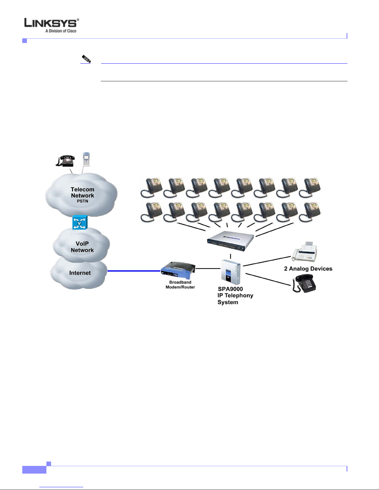
Figure 1-1 illustrates how the IP phones are connected in a VoIP network.
Figure 1-1 Linksys IP Phones in a VoIP Network
Chapter 1 Introducing Linksys IP Phones
PA100 power supply must be ordered separately if you are not using a PoE switch.
Linksys IP Phone Features
The following telephony features are provided by the differen t models of Linksys IP phon es. An asterisk
(*) indicates that the feature requires support by the SIP server.
:
• Shared Line Appearance *
–
SPA901: Two Call Appearances Accessed Via Flash Key or Hook-Flash
–
WIP310, SPA921, and SPA922: Two call appearances
–
SPA941 and SPA942: Four call appearances
–
SPA962: Six call appearances
• Line Status Indicators
• Call Hold
Linksys IP Phone Administrator Guide
1-2
Firmware Version 5.1
Page 14

Chapter 1 Introducing Linksys IP Phones
• Music on Hold *
• Call Waiting
• Outbound Caller ID Blocking
• Call Transfer - Attended and Blind
• Call Conferencing
• Call Pick Up - Selective and Group *
• Call Park and UnPark *
• Call Swap
• Call Back on Busy
• Call Blocking - Anonymous and Selective
• Call Forwarding - Unconditional, No Answer, On Busy
• Hot Line and Warm Line Automatic Calling
• Call Logs (60 entries each): Made, Answered, and Missed Calls
• Do Not Disturb (callers hear line busy tone)
• URI (IP) Dialing Support (Vanity Numbers)
• Date and Time with Intelligent Daylight Savings Support
• Call Duration and Start Time Stored in Call Logs
Linksys IP Phone Features
• Ten-User Downloada ble Ring Tones - Ring Tone Generator Free from www.linksys.com
• Speed Dialing
• Automatic Redial
• Configurable Dial/Numbering Plan Support - per Line
• Intercom *
• Group Paging *
• DNS SRV and Multiple A Records for Proxy Lookup and Proxy Redundancy
• Syslog, Debug, Report Generation, and Event Logging
• Secure Call Encrypted Voice Communication Support
• Built-in Web Server for Administration and Configuration with Multiple Security Levels
• Automated Provisioning, Multiple Methods. Up to 256-Bit Encryption: (HTTP, HTTPS, TFTP)
• Optionally Require Admin Password to Reset Unit to Factory Defaults
• NAT Traversal
• Set Preferred CODEC, Per Call, All Calls
• Call Return - Redial Last Caller
• Configurable Dial/Numbering Plan Support
• Support Linksys Voice System Automatic Configuration
Firmware Version 5.1
Linksys IP Phone Administrator Guide
1-3
Page 15

Linksys IP Phone Features
SPA901 Features
The SP A901 prov ides the following features that are not needed with the Linksys IP phon es that prov ide
an LCD display:
• Built-in Interactive Voice Response (IVR) system to check status and change configuration
• Ringer and Handset Vo lume Controls
• Handset Input Gain Adjustment
SPA92x, SPA94x, SPA962
The SPA921, SPA922, SPA941, SPA942, and SPA962 provide an LCD display and ad ditional featur es
that are not provided with the SPA901, including the following:
• Line Status Indicators: Active Line, Name, and Number
• Menu-Driven User Interface
• Digits Dialed with Number Auto-Completion
• Caller ID Name and Number and Outbound Caller ID Blockin g
• On-Hook Dialing
Chapter 1 Introducing Linksys IP Phones
• Redial from Call Logs
• Personal Directory with Auto-dial (100 entries)
• On Hook Default Audio Configuration (Speakerphone and Headset)
• Called Number with Directory Name Matching
• Call Number using Name - Directory Matching or via Caller ID
• Subsequent Incoming Calls with Calling Name and Number
• Name and Identity (Text) Displayed at Start Up
• Distinctive Ringing Based on Calling and Called Number
Ensuring Voice Quality
Voice quality perceived by the subscribers of the IP T elephony service shoul d be indistingui shable from
that of the PSTN. Voice quality can be measured with such methods as Perceptual Speech Quality
Measurement (PSQM), with a scale of 1–5, in which lower is better; and Mean Opinion Score (MOS),
with a scale of 1–5, in which higher is be tter.
Table 1-2 displays speech quality metrics associated with various audio compression algorithms. For
information about bandwidth requirements for each supported codec, refer to Table 2-1 on page 2-10.
Table 1-2 Speech Quality Metrics
Algorithm Complexity MOS Score
G.71 1 Very low
G.726 Low 4.1 (32 kbps)
G.729a Low–medium 4
Linksys IP Phone Administrator Guide
1-4
4.5
Firmware Version 5.1
Page 16

Chapter 1 Introducing Linksys IP Phones
Table 1-2 Speech Quality Metrics
G.729 Medium 4
G.723.1 High 3.8
Note Linksys IP phones support all the above voice coding algorithms.
Feature Descriptions
Linksys IP phones are full featured, fully programmable IP phones that can be custom provisioned
within a wide range of configuration parameters. This chapter contains a high-level overview of features
to provide a basic understand ing of the feature bread th and cap abilities o f Linksys IP p hones.
• SIP Proxy Redundancy, page 1-5
• Supported Codecs, page 1-6
• Other Features, page 1-7
Feature Descriptions
SIP Proxy Redundancy
In typical commercial IP Telephony deployments, all calls are established through a SIP proxy server.
An average SIP proxy server may handle tens of thousands of subscribers. It is important that a backup
server be available so that an active server can be temporarily switched out for maintenance. Linksys IP
phones support the use of backup SIP proxy servers so that service disruption should be nearly
eliminated.
A simple way to support proxy redundancy is to configure a SIP proxy server in the Linksys IP phone
configuration profile.
a. In Linksys SPA Configuration menu web GUI, enter your service provider name in the Proxy field.
The system
b. In the DNS SRV Auto Prefix filed, enter Yes.
c. In the User DNS SRV field, enter Yes.
d. The phone tries to register and the server sends a list of IP addresses in order of priority.
(automatically)
where the list is arranged in order of priority. The Linksys IP phone attempts to contact the highest priority
proxy server whenever possible.
The dynamic nature of SIP message routing makes the us e of a static list of proxy servers inadequate in
some scenarios. In deployments where user agents are served by different domains, for instance, it would
not be feasible to configure one static list of proxy servers per covered domain into every Linksys IP
phone. One solution to this situation is through the use of DNS SRV records. Linksys IP phones can be
instructed to contact a SIP proxy server in a domain named in SIP messages. The Linksys IP phone
consults the DNS server to get a list of hosts in the given domain that provides SIP services. If an entry
exists, the DNS server returns an SRV record that contains a list of SIP proxy servers for the domain,
with their host names, priority, listening ports, and so on. The Linksys IP phone tries to contact the list
of hosts in the order of their stated priority.
Firmware Version 5.1
Linksys IP Phone Administrator Guide
1-5
Page 17

Feature Descriptions
If the Linksys IP phone is currently using a lower priority proxy server, it periodically probes the higher
priority proxy to see whether it is back on line, and attempts to switch back to the higher priority proxy
whenever possible.
Supported Codecs
Negotiation of the optimal voice codec sometimes depends on the ability of Linksys IP p hone to “match”
a codec name with the far-end device/gateway codec name. Linksys IP phones allow the network
administrator to individually name the various codecs that are supported such that the correct codec
successfully negotiates with the far-end equipment.
The administrator can select the low-bit-rate codec used for each line. G.711a and G.711u are always
enabled. Table 1-3 describes the codecs supported by the Linksys IP phones.
Table 1-3 Codecs Supported by Linksys IP Phones
Codec (Voice Compression
Algorithm) Description
G.711 (A-law and mµ-law) This very low complexity codec supports uncompressed 64 kbps
G.726 This low complexity codec supports compressed 16, 24, 32, and 40
G.729A The ITU G.729 voice coding algorithm is used to compress
G.723.1 Linksys IP phones support the use of ITU G.723.1 audio codec at
Chapter 1 Introducing Linksys IP Phones
digitized voice transmission at one through ten 5 ms voice frames
per packet. This codec provides the highest voice quality and uses
the most bandwidth of any of the available codecs.
kbps digitized voice transmission at one through ten 10 ms voice
frames per packet. This codec provides high voice quality.
digitized speech. Linksys supports G.729. G.729A is a reduced
complexity version of G.729. It requires about half the processing
power to code G.729. The G.729 and G.729A bit streams are
compatible and interoperable, but not identical.
6.4 kbps. Up to two channels of G.723.1 can be used
simultaneously. For example, Line 1 and Line 2 can be using
G.723.1 simultaneously, or Line 1 or Line 2 can initiate a three-way
conference with both call legs using G.723.1.
When no static payload value is assigned per RFC 1890, Linksys IP phones can support dynamic
payloads for G.726.
Linksys IP Phone Administrator Guide
1-6
Firmware Version 5.1
Page 18

Chapter 1 Introducing Linksys IP Phones
Other Features
Table 1-4 summarizes the features provided by Linksys IP Phones.
Table 1-4 Linksys Phone Features
Feature Description
Music On Hold On a connected call, Linksys IP phones may place the rem ote pa rty on ca ll .
Secure Calls A user (if enabled by service provider or administrator) has the option to
Adjustable Audio
Frames Per Packet
DTMF In-Band and Out-of-Band (RFC 2833) (SIP INFO) Lin ksys IP phon es may
Call Progress Tone
Generation
Call Progress T one Pass
Through
Jitter Buffer—Dynamic
(Adaptive)
Feature Descriptions
If the remote party indicates that they can still recei ve audio while t he call is
holding, the MOH server sends streaming audio.
make an outbound call secure in the sense that the audio packets in both
directions are encrypted.
This feature allows you to set the number of audio frames contained in one
RTP packet. Packets can be adjusted to contain from 1–10 audio frames.
Increasing the number of packets decreases the bandwidth utilized, but it
also increases delay and may affect voice quality.
relay DTMF digits as out-of-band events to preserv e the fidelity of the digits.
This can enhance the reliability of DTMF transmission required by many
IVR applications such as dial-up banking and airline information.
Linksys IP phones have configurable call progress tones. Parameters for
each type of tone may include number of frequency components, frequency
and amplitude of each component, and cadence information.
This feature allows you to hear the call progress tones (such as ringing) that
are generated from the far-end network.
Linksys IP phones can buffer incoming voice packets to minimize
out-of-order packet arrival. This process is known as jitter buffering. The
jitter buffer size proactively adjusts or adapts in size, depen ding on changing
network conditions.
Linksys IP phones have a Network Jitter Level control setting for each line
of service. The jitter level decides how aggressively Linksys IP phones try
to shrink the jitter buffer over time to achieve a lower overall delay. If the
jitter level is higher, it shrinks more gradually. If jitter level is lower, it
shrinks more quickly.
Firmware Version 5.1
Linksys IP Phone Administrator Guide
1-7
Page 19

Technology Background
Table 1-4 Linksys Phone Features (continued)
Feature Description
Voice Activity
Detection with Silence
Suppression and
Comfort Noise
Generation
Configurable Dial Plan
with Interdigit Timers
Voice Activity Detection (VAD) with Silence Suppression is a means of
increasing the number of calls supported by the network by reducing the
required bidirectional bandwidth for a single call. VAD uses a very
sophisticated algorithm to distinguish between speech and non-speech
signals. Based on the current and past statistics, the VAD algorithm decides
whether or not speech is present. If the VAD algorithm decides speech is not
present, the silence suppression and comfort noise generation is activated.
This is accomplished by removing and not transmitting the natural silence
that occurs in normal two-way connection. The IP bandwidth is used only
when someone is speaking. During the silent periods of a telephone call,
additional bandwidth is available for other voice calls or data traffic because
the silence packets are not being transmitted across the network. Comfort
Noise Generation provides artificially-generated background white noise
(sounds), designed to reassure callers that their calls are still connected
during silent periods. If Comfort Noise Generation is not used, the caller
may think the call has been disconnected because of the “dead silence”
periods created by the VAD and Silence Suppression feature.
Linksys IP phones have three configurable interdigit timers:
• Initial timeout (T)—Handset off hook; no digit pressed yet.
Chapter 1 Introducing Linksys IP Phones
Report Generation and
Event Logging
Syslog and Debug
Server Records
Dynamic Payload When no static payload value is assigned per RFC 1890, Linksys IP phones
Call Statistics and
Reporting
Technology Background
• Long timeout (L)—One or more digits pressed, more digits needed to
reach a valid number (as per the dial plan).
• Short timeout (S)—Current dialed number is valid, but more digits
would also lead to a valid number.
Linksys IP phones report a variety of status and error reports to assist service
providers in diagnosing problems and evaluating the performance of their
services. The information can be queried by an authorized agent, using
HTTP with message-digest authentication, for instance. The information
may be organized as an XML page or HTML page.
Linksys IP phones support detailed logging of all activities for further
debugging. The debug information may be sent to a configured Syslog
server. Linksys IP phones provide configuration settings that determine the
type of activity/events that should be logged as, for example, a debug level
setting.
can support dynamic payloads for G.726.
The statistics collected by Linksys IP phones during normal operation
statistics are available in the Info tab. Line status is reported fo r each line (1
and 2). Each line maintains up to 2 calls: Call 1 and 2.
This section provides background information about the technology and protocols used by the phone:
• Session Initiation Protocol, page 1-9
Linksys IP Phone Administrator Guide
1-8
Firmware Version 5.1
Page 20
Chapter 1 Introducing Linksys IP Phones
• Using Linksys IP Phones with a Firewall or Router, page 1-9
• Using Linksys IP Phones with a Firewall or Router, page 1-9
Session Initiation Protocol
Linksys 900 Series IP phones are implemented using open standards, such as Session Initiation Protocol
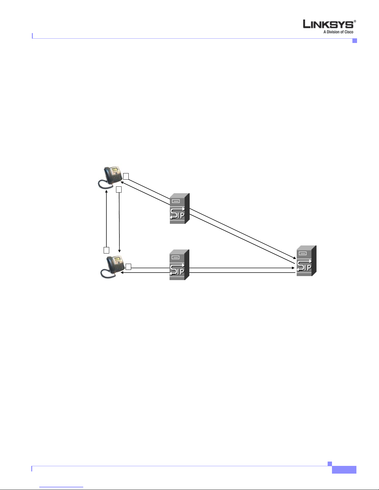
(SIP), allowing interoperation with all ITSPs supporting SIP. Figure 1-2 illustrates a SIP request for
connection to another subscriber in the network. The requestor is called the user agent server (UAS),
while the recipient is called the user agent client (UAC).
Figure 1-2 SIP Requests and Responses
SIP UA
2
4
Technology Background
SIP Proxy
RTP
3
SIP Proxy
1
SIP UA
In a SIP VoIP network, when the SIP proxy receives a request from a UAS for a connection and it does
not know the location of the UAC, it forwards the message to another SIP proxy in the network. Once
the UAC is located and the resp onse is routed back to the UAS, a direct peer-to-peer session is
established between the two UAs. The actual voice traffic is transmitted between UAs over dynamically
assigned ports using the Real-time Protocol (RTP).
Using Linksys IP Phones with a Firewall or Router
When using a Linksys IP phone behind a firewall or router, make sure that the following ports are not
blocked:
• SIP ports—By default, UDP port 5060 and 5061
• RTP ports—16384 to 16482
SIP Proxy
If security is not a concern in your environment, you can consider disabling SPI, if this function exists
on your firewall.
Firmware Version 5.1
Linksys IP Phone Administrator Guide
1-9
Page 21
Technology Background
Network Address Translation
This section describes issues that arise when using the LVS system on a network behind a network
address translation (NAT) device. It includes the following topics:
• NAT Overview, page 1-10
• NAT Types, page 1-11
• Simple Traversal of UDP Through NAT (STUN), page 1-11
• SIP-NAT Interoperation, page 1-12
NAT Overview
Network Address Translation (NAT) allows multiple devices to share the same public, routable, IP
address for establishing connections over the Internet. NAT is typically performed by a router that
forwards packets between the Internet and the internal, private network.
The association between a private address and port and a public address and port is called a NAT
mapping. This mapping is maintained for a short period of time, that varies from a few seconds to several
minutes. The expiration time is extended whenever the mapping is used to send a packet from the source
device.
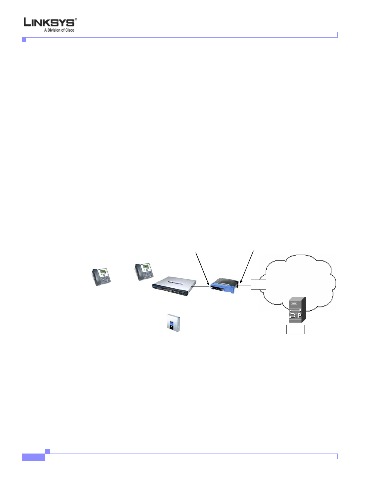
The ITSP may support NAT mapping using a Se ssion Border Controller (s ee Figure 1-3).
Chapter 1 Introducing Linksys IP Phones
Figure 1-3 NAT Support with Session Border Controller Provided by ITSP
192.168.1.101
Private IP address
192.168.1.1
192.168.1.102
NAT Device
DHCP
server
External IP address
assigned by ISP
ISP
Internet
SPA9000
ITSP
SIP Proxy
192.168.1.100
Session Border
Controller
This is the preferred option because it eliminates the need for managing NAT on the Linksys IP phone.
If this is not available, you need to discuss with the ITSP how to use the NAT Support Parameters
provided by the Linksys IP phone, such as <Outbound Proxy> and <STUN Server Enable>.
A typical application of NAT allows all the devices in a subscriber network to access the Internet through
a router with a single public IP address assigned by an ISP. The IP header of the packets sent from the
private network to the public network is substituted by NAT with the public IP address and a port
assigned by the router. The receiver of the packets on the public network sees the packets as coming
from the external address instead of the private address of the device.
Linksys IP Phone Administrator Guide
1-10
Firmware Version 5.1
Page 22

Chapter 1 Introducing Linksys IP Phones
NAT Types
The ways that NAT is implemented can be divided into the following categories:
• Full cone NAT—Also known as one-to-one NAT. All requests from the same internal IP address
and port are mapped to the same external IP address and port. An external host can send a packet to
the internal host, by sending a packet to the mapped external address
• Restricted cone NAT—All requests from the same internal IP address and port are mapped to the
same external IP address and port. Unlike a full cone NAT, an external host can send a packet to the
internal host only if the internal host had previously sent a packet to it.
• Port restricted cone NAT/symmetric NAT—Port restricted cone NAT or symmetric NAT is like a
restricted cone NAT, but the restriction includes port numbers. Specifically, an external host can
send a packet to a particular port on the internal host only if the internal host had previously sent a
packet from that port to the external host.
With symmetric NAT, all requests from the same internal IP address and port to a specific destination
IP address and port are mapped to a unique external source IP address and port. I f the same internal host
sends a packet with the same source address and port to a different destination, a different mapping is
used. Only an external host that receives a packet can send a UDP packet back to the internal host.
Simple Traversal of UDP Through NAT (STUN)
Technology Background
Simple Traversal of User Datagram Protocol (UDP) through Network Address Translators (NATs), or
STUN, is a protocol defined by RFC 3489 that allows a client behind a NAT device to determine its
public address, the type of NAT implemented, and the port associated on the Internet connection with a
particular local port. This information is used to set up UDP communication between two hosts that are
both behind NAT routers. Open source STUN software can be obtained at the following website:
http://www.voip-info.org/wiki-Open+Source+VOIP+Software
STUN does not work with a symmetric NAT router. To determine the type of NAT your router uses,
complete the following steps:
Enable debugging on the Linksys IP phone:
1. Make sure you do no t have firewall runn ing on you r PC that could bl ock the syslog por t (by default
this is 514).
2. On the administration web server , System tab, set <Debug Server> to the IP address and port number
of your syslog server.
Note that this address and port number has to be reachable from the Linksys IP phone.
3. Set <Debug level> to 3, but do not change the value of the <syslog server> parameter.
4. To capture SIP signaling messages, under the Line tab, set <SIP Debug Option> to Full. The output
is named syslog.514.log.
5. To determine the type of NAT your router is using set <STUN Test Enable> to yes.
6. View the debug messages to determine if your network uses symmetric NAT.
Firmware Version 5.1
Linksys IP Phone Administrator Guide
1-11
Page 23

Technology Background
SIP-NAT Interoperation
In the case of SIP, the addresses where messages/data should be sent to a Linksys IP phone system are
embedded in the SIP messages sent by the device. If the Linksys IP phone system is located behind a
NAT device, the private IP address assigned to it is not usable for communications with the SIP entities
outside the private network.
Note The ITSP might offer an outbound NAT-Aware proxy, which discovers the public IP address from the
remote endpoint and eliminates the need to modify the SIP message from the UAC.
The Linksys IP phone system must substitute the private IP address information with the pro per external
IP address/port in the mapping chosen by the underlying NAT to communicate with a particular public
peer address/port. For this, the Linksys IP phone system must perform the following tasks:
• Discover the NAT mappings used to communicate with the peer.
This can be done with the help of an external device, such as a STUN server. A STUN server
responds to a special NAT-Mapping-Discovery request by sending back a message to the source IP
address/port of the request, where the message contains the source IP address/port of the original
request. The Linksys IP phone system can send this request when it first attempts to communicate
with a SIP entity over the Internet. It then stores the mapping discovery results returned by the
server.
• Communicate the NAT mapping information to the external SIP entities.
Chapter 1 Introducing Linksys IP Phones
If the entity is a SIP Registrar, the information should be carried in the Contact header that
overwrites the private address/port information. If the entity is another SIP UA when establishing a
call, the information should be carried in the Contact header as well as in the SDP embedded in SIP
message bodies. The VIA header in outbound SIP requests might also need to be substituted with
the public address if the UAS relies on it to route back responses.
• Extend the discovered NAT mappings by sending keep-alive packets.
Because the mapping is alive only for a short period , the Linksys IP phone sy stem continues to send
periodic keep-alive packets through the mapping to extend its validity as necessary.
Linksys IP Phone Administrator Guide
1-12
Firmware Version 5.1
Page 24

CHA P T E R
2
Getting Started
This chapter describes the tools and utilities available for administering Linksys phones. It includes the
following sections:
• Linksys 900 Series IP Phones, page 2-1
• SPA9000 IP PBX System, page 2-9
• Establishing Connectivity, page 2-9
• Using the Administration Web Server, page 2-12
• Web Interface URLs, page 2-14
• Provisioning, page 2-15
• Using the Interactive Vo ice Response Interfac e, page 2-1 6
Note If the Linksys IP phone is supplied or sponsored b y an Internet Telephone Service Provider (ITSP),
certain network and service settings may be preconfigured. Depending on the configuration policy,
access by an end user to specific configuration settings may be restricted or blocked.
Linksys 900 Series IP Phones
The Linksys provides fully-featured VoIP phones that integrate with the Linksys SPA9000 to provide
connectivity to other local stations, and through an ITSP to IP phones over the Internet, In addition, t he
optional SPA400 integrates with the SPA9000 and provides connectivity between SPA900 IP phones
and the PSTN. This section summarizes the ports and hardware features provided by each device. It
includes the following topics:
• Caring for Your Hardwa re, page 2-2
• SPA901, page 2-2
• SPA92x, SPA94x, and SPA962 Hardware Features, page 2-3
• SPA92x, SPA94x, and SPA962 Hardware Features, page 2-3
• SPA922, page 2-5
• SPA932, page 2-5
• SPA941, page 2-6
Firmware Version 5.1
Linksys IP Phone Administrator Guide
2-1
Page 25
Linksys 900 Series IP Phones
• SPA942, page 2-7
• SPA962, page 2-8
Caring for Your Hardware
The Linksys 900 Series IP phones are electronic devices that should not be exposed to excessive heat,
sun, cold or water. To clean the equipment, use a slightly moistened paper or cloth towel. Do not spray
or pour cleaning solution directly onto the hardware unit.
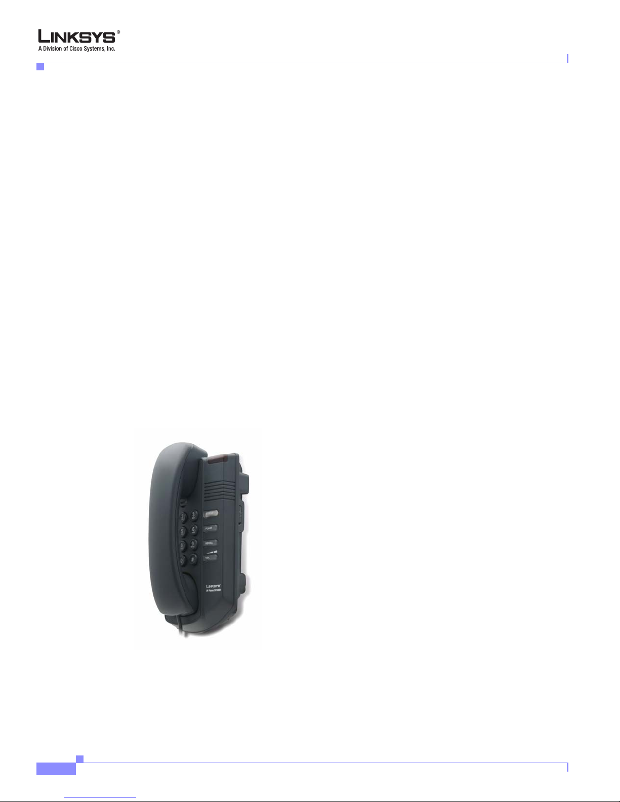
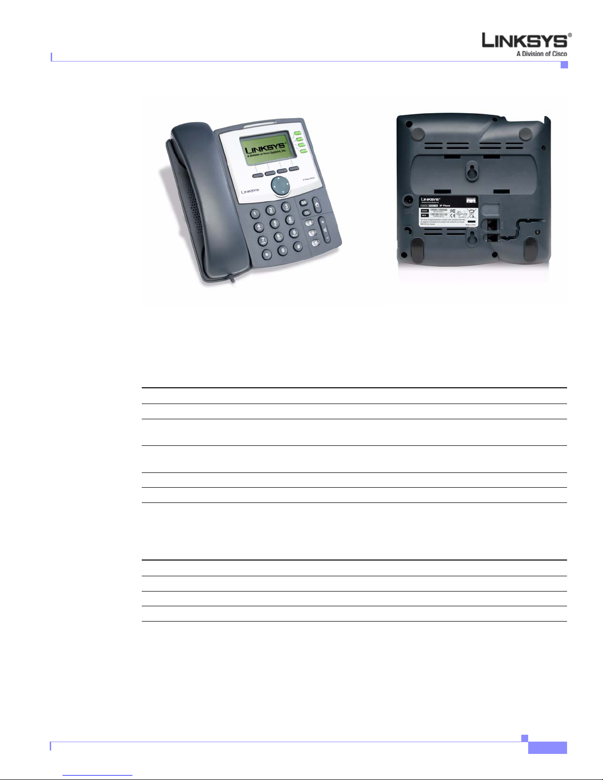
SPA901
The SPA901 provides an entry-level IP phone that can be w all mounted (see Figure 2-1). The following
are the hardware features provided by the SPA901:
• Voice Mail Message Waiting Indicator Light
• Redial Button
• Dedicated Flash Button
• Volume Control Button Cycles Through Volume Levels. Controls Ringer and Handset Volume.
• Standard 12-Button Dialing Pad
• High Quality Handset and Cradle
Chapter 2 Getting Started
• Ethernet LAN – 10BaseT RJ-45
• 5-volt DC Universal (100-240 Volt) Switching Power Adaptor
Figure 2-1 SPA901
The following tables describe the status indicators and controls on the front of the device and the port s
on the back panel of the device.
Linksys IP Phone Administrator Guide
2-2
Firmware Version 5.1
Page 26

Chapter 2 Getting Started
Front Panel and Side of Phone
Feature Function
Message waiting light On: you have a voicemail message.
STATUS Off: make a call. On: make a call; line is shared. Flashing: shared
FLASH Press to pickup a second incoming call, transfer a call, or setup a
REDIAL Press the redial the last number called.
Back Panel
Port Function
Phone jack Connect to the handset.
Ethernet port Connect to the SPA9000 through a local switch.
Power Connect to the 5-volt power supply.
Linksys 900 Series IP Phones
line on hold. On red: line in use. Flashing red: local call on hold. On
orange: phone not registered.
three-way conference call.
SPA92x, SPA94x, and SPA962 Hardware Features
The SPA941, SPA942, and SPA962 provide LCD displays and other additional hardware features,
including the following:
• Four Illuminated Call Appearance Line Buttons with Tricolor LED's (six LED’s on the SPA962)
• LED Indicates Line State – Active, Idle, On-Hold, Unregistered
• Line LED Configurable to 13 Different States (See “Line Key LED Pattern” section on page 5-31).
• Dedicated Illuminated Buttons for:
• Audio Mute On/Off
• Headset On/Off
• Speakerphone On/Off
• Four Soft Key Buttons
• Four Way Rocking Directional Knob for Menu Navigation
• Voice Mail Message Waiting Indicator Light
• Voice Mail Message Retrieval Button
• Dedicated Hold Button
• Settings Button for Access to Feature, Set-up, and Configuration Menus
• Volume Control Rocking Up/Down Knob Controls Handset, Headset, Speaker, Ringer
• Standard 12-Button Dialing Pad
• High Quality Handset and Cradle
Firmware Version 5.1
Linksys IP Phone Administrator Guide
2-3
Page 27
Linksys 900 Series IP Phones
SPA921
Chapter 2 Getting Started
• Built-In High Quality Microphone and Speaker
• Headset Jack – 2.5 millimeter
• Two Ethernet LAN ports (100BaseT RJ-45)
• 802.3af Compliant Power over Ethernet (PoE) (not available on SPA9x1 models)
• Optional 5 volt DC Universal (100-240 Volt) Switching Power Adaptor - Power Supply is Ordered
Separately
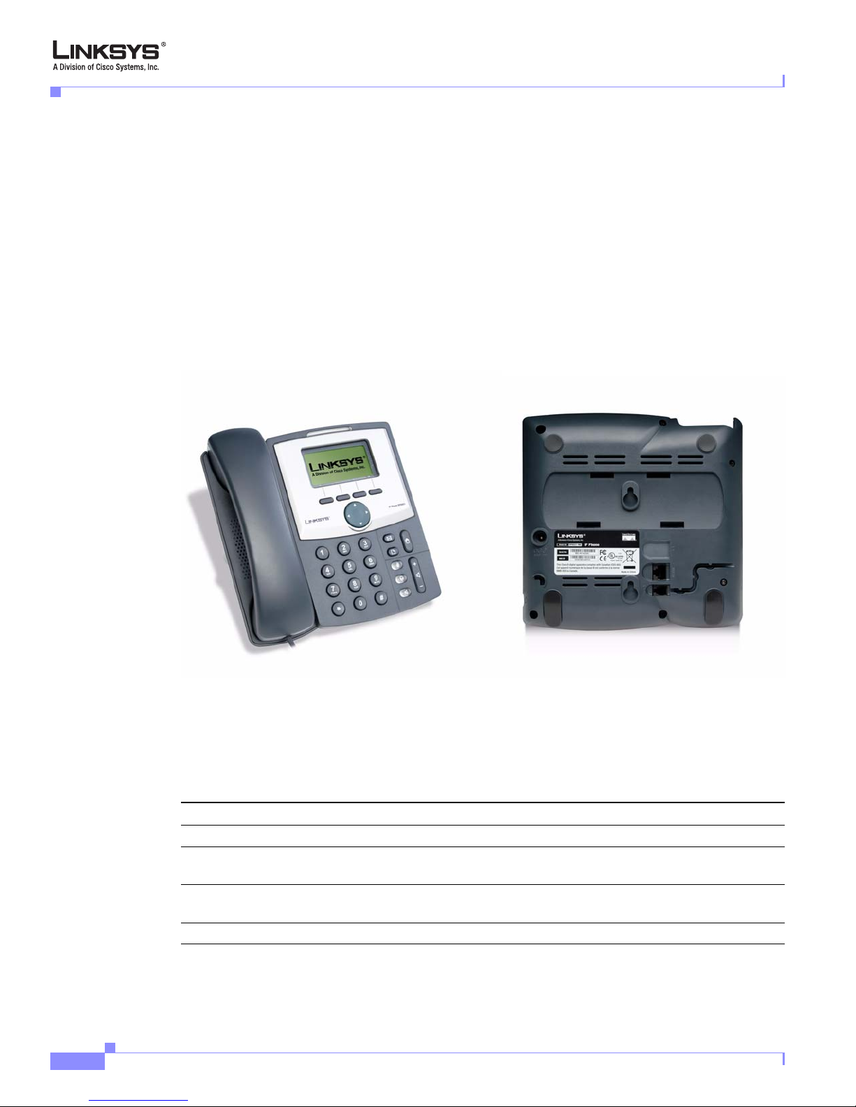
The SPA921 has one RJ-11 phone port and one 100BaseT RJ-45 port for connecting the phone to the
LAN (see Figure 2-2).
Figure 2-2 SPA921
The following tables describe the status indicators and controls on the front of the device and
the ports on the back panel of the device.
Front Panel
Feature Function
LCD display Lists device status and configuration options.
Telephone keypad Enters numeric digits for initiating a call or for entering
Navigation button Scrolls between display and configuration options in the LCD
Soft keys 1-4 Selects options on the LCD display
Linksys IP Phone Administrator Guide
2-4
configuration information.
display.
Firmware Version 5.1
Page 28
Chapter 2 Getting Started
Back Panel
SPA922
Linksys 900 Series IP Phones
Port Function
Phone jack Connects to the handset.
Ethernet ports Connects to the SPA9000 through a local switch. The SPA922 has
two ports. Use the other port to connect to a PC or other LAN
device.
Power Connect to the 5-volt power supply.
The SPA922 is similar to the SPA921, but provides Power over Ethernet (PoE) and an extra Ethernet
port for connecting another device to the LAN (see Figure 2-3). The SPA100 power supply must be
ordered separately if you are not using a PoE switch.
Figure 2-3 SPA922
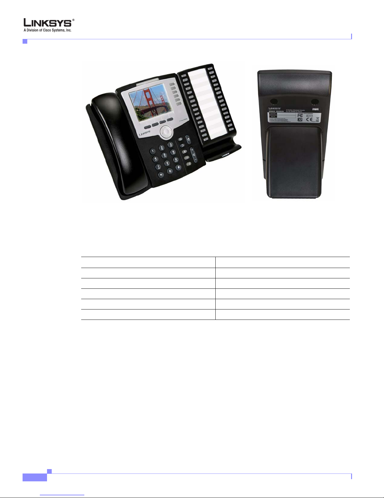
SPA932
The SPA932 is a 32-button attendant console for the SPA962, providing 32 three-color (red, green, and
amber) programmable LEDS, with support for Broadsoft Busy Lamp Field and Asterisk Line
Monitoring (see Figure 2-4). The SPA932 attaches to the SPA962 with the attachment arm provided (not
shown). It obtains power directly from the SPA962 and does not require a separate power supply. Two
SPA932 units can be attached to a single SPA962 to monitor a total of 64 separate lines.
Firmware Version 5.1
Linksys IP Phone Administrator Guide
2-5
Page 29
Linksys 900 Series IP Phones
Figure 2-4 SPA932 (Front View with SPA962)
Each SPA932 unit provides 32 programmable speed-dial or direct station select (DSS) buttons, Each
lighted button indicates line status (idle, ringing, busy, or null) using a busy lamp field (BLF) . Incoming
calls can be immediately transferred to the proper location by pushing a button assigned to the exten sion
on the SPA932.
The following table summarizes the meaning of each light color and pattern.
Chapter 2 Getting Started
SPA941
Port/LED Meaning
AUX IN Connects to the SPA962
AUX OUT Connects to a second SPA932 unit (optional)
Green Idle
Red In-use
Blinking Red Ringing
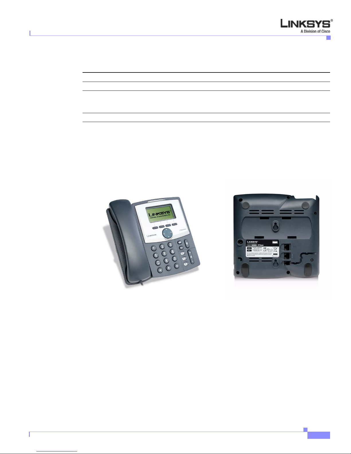
The SPA941 provides four lines (see Figure 2-5).
Linksys IP Phone Administrator Guide
2-6
Firmware Version 5.1
Page 30
Chapter 2 Getting Started
Linksys 900 Series IP Phones
Figure 2-5 SPA941
The following tables describe the status indicators and controls on the front of the device and the port s
on the back panel of the device.
Front Panel
Back Panel
SPA942
Feature Function
LCD display Lists device status and configuration options.
Telephone keypad Enters numeric digits for initiating a call or for entering
configuration information.
Navigation button Scrolls between display and configuration options in the LCD
display.
Soft keys 1-4 Selects options on the LCD display.
Line status indicators 1-4 Displays status of each extension.
Port Function
Phone jack Connects to the handset.
Ethernet ports Connects to the SPA9000 through a local switch.
Power Connects to the 5-volt power supply.
The SPA942 is similar to the SPA941, but provides two Ethernet ports for connecting to the LAN and
supports Power over Ethernet (see Figure 2-6). The PA100 power supply must be ordere d separately if
you are not using a PoE switch. See the table for SPA941.
Firmware Version 5.1
Linksys IP Phone Administrator Guide
2-7
Page 31

Linksys 900 Series IP Phones
SPA962
Chapter 2 Getting Started
Figure 2-6 SPA942
The SPA962 has a 320 x 240 true color, four-inch, LCD, provides up to six telephone extensions, and
supports PoE (see Figure 2-7). The P A 100 power suppl y must be ordered separately if you are not usin g
a PoE switch.
Figure 2-7 SPA962
The following tables describe the status indicators and controls on the front of the device and the port s
on the back panel of the device.
Linksys IP Phone Administrator Guide
2-8
Firmware Version 5.1
Page 32

Chapter 2 Getting Started
Front Panel
Back Panel
SPA9000 IP PBX System
Feature Function
Full-color LCD display Lists device status and configuration options.
T elephone keypad Enters numeric digits for initiating a call or for entering configuration
information.
Navigation button Scrolls between display and configuration options in the LCD display.
Soft keys 1-4 Selects options on the LCD display.
Line status indicators 1-6 Displays status of each extension.
Port Function
Phone jack Connects to the handset.
Ethernet ports (2) Connects to the SPA9000 through a local switch. Use the second port
to connect to a PC or other LAN device.
Power Connects to the 5-volt power supply.
AUX RJ-11 port Connects to optional SPA932
SPA9000 IP PBX System
The SPA9000 IP PBX System (VoIP side), along with the SPA400, which is Internet Telephony
Gateway, provides for an analog line and voicemail.
The system provides auto attendant features for multiple extensions. Features include:
• Auto Attendant
• Shared line appearances
• Configurable call routing
• Multiple DID numbers per VoIP line
• Call hunting (sequential, round robin, random)
• Call transfer and Call forward
• Call hold and Call waiting
You can perform SPA9000 administrative tasks using an Interactive Voice Response (IVR) system or a
built-in Web Server.
Establishing Connectivity
This section describes how to connect the SPA900 Series IP phone hardware. It includes the following
topics:
• Bandwidth Requirements1, page 2-10
Firmware Version 5.1
Linksys IP Phone Administrator Guide
2-9
Page 33

Establishing Connectivity
• Installing the SPA900 Series IP Phone, page 2-10
Bandwidth Requirements1
Depending on how you have your IP phones configured, each call requires 55 to 110 kbps in each
direction. Therefore, using G.729 as the voice codec setting, and with an average business-grade
broadband Internet connection supporting 1.5 Mbps downstream and 384 kbps upstream , a total of seven
(7) simultaneous conversations can be reliably supported with adequate bandwidth available for file
downloads.
Linksys recommends using the Linksys IP phone with QoS-capable networking equipment that can
prioritize the VoIP application traffic. QoS features are available on many Linksys data networking
switches and routers. A QoS-en ab led ro uter p rio ritizes the packets going upstream to the ISP. Table 2-1
illustrates the bandwidth budget using different codecs.
Table 2-1 Ethernet Bandwidth Budget for Off-Net VoIP Calling
Approximate bandwidth budget for
Codec
G.711 110 kbps 220 kbps 440 kbps 660 kbps 880 kbps
G.726-40 87 kbps 174 kbps 348 kbps 522 kbps 696 kbps
G.726-32 79 kbps 158 kbps 316 kbps 474 kbps 632 kbps
G.726-24 71 kbps 142 kbps 284 kbps 426 kbps 568 kbps
G.726-16 63 kbps 126 kbps 252 kbps 378 kbps 504 kbps
G.729 55 kbps 110 kbps 220 kbps 330 kbps 440 kbps
each side of conversation 2 calls 4 calls 6 calls 8 calls
Chapter 2 Getting Started
This table is based on the following assumptions:
• Bandwidth Calculated with No Silence Suppression
• 20 Millisecond of payload per RTP packet
Note The use of silence suppression can reduce the average bandwidth budget by 30% or more.
For more information about bandwidth calculation, refer to the following websites:
http://www.erlang.com/calculator/lipb/
http://www.packetizer.com/voip/diagnostics/bandcalc.html
Installing the SPA900 Series IP Phone
This section describes how to install and verify operation of SPA900 Series IP phones.
Check to make sure that you have the following package contents:
• Linksys 900 Series phone
• Ethernet cable
• Power adapter (must be ordered separately for PoE units: SPA922, SPA942, and SPA962)
Linksys IP Phone Administrator Guide
2-10
Firmware Version 5.1
Page 34

Chapter 2 Getting Started
Assembling the Phone and Connecting to the Network
Perform the following steps to connect Linksys IP phone.
Step 1 Find the end of the coiled phone cord that has the longer straightened end. Plug that end into the back
of the phone base (phone symbol).
Step 2 Plug in the short straightened end of the handset cord into the jack at the bottom of the handset.
Step 3 If you are using an external power source, push the power cord into the power supply, and plug the power
supply into the phone base unit. Use only the power supply that came with the phone. SPA922, SPA942
and SPA962 can be configured without external power, if connecting to an IEEE powered Ethernet
switch. See Linksys.com for details.
Step 4 Plug the Ethernet cable into the back of the base station.
Step 5 Plug the other end of the Ethernet cable into your already prepared network connection.
If the phone is configured using an optional PoE adapter, see the PoE device documentation for setup
instructions.With the SPA922, SPA942, and SPA962, the second Ethernet port can be used to connect a
PC. The AUX RJ-11 port on the SPA962 is reserved for SPA 932 use.
Note Do NOT plug a telephone line into the AUX port.
Establishing Connectivity
Attaching the Desk Stand
This and the following sections app ly to a SPA900 Series IP phone with an LCD display. For
information regarding the SPA901 IP phone, refer to the SPA901 QuickStart Guide.
Step 1 Line up the tabs on the desk stand with the slots on the back of the phone.
Step 2 Slide the bottom ta bs into th e slots
Step 3 Lightly press down on the t op of the de sk stand. It should easily slid e into the top slots. Do not force.
Mounting the Phone to the Wall
Note When mounting the phone to a wall, do not attach the desk stand.
Step 1 Attach two appropriate screws to the wall. Leave 1/4” distance from the wall. This allows you to slide
the mounting brackets on to the screws.
Step 2 Push down slightly to lock the phone in place.
You can purchase an optional wall mount kit (MB100) from your retailer or Linksys.com.
Firmware Version 5.1
Linksys IP Phone Administrator Guide
2-11
Page 35

Using the Administration Web Server
Turning on the Phone
If you are using an external power source, instead of Power over Ethernet (PoE), plug the adapter to an
electrical outlet. Use only the adapter supplied for the specific phone.
• The phone executes a boot-up sequence when the power source is connected.
• During this sequence, the display first shows LINKSYS® or a customized message and then
“Initializing Network.”
• All of the lights on the phone flash.
• After the sequence, which should take about five seco nds, the phone displays the standard menu for
the phone.
• The date, name, and number of the phone will display on the top line of the LCD screen.
At the bottom of the LCD screen, redial, dir, cfwd, and dnd are displayed over their associated soft
buttons. A small arrow appears next to dnd indicating that more menus can be accessed by pushing the
right side of the navigation button.
If the phone does not display the appropriate screen, verify the installation and connectivity. If these are
correct, try unplugging the phone and plugging it back in again. If you still do not see the display, refer
to the “Troubleshooting FAQ” section on page 3-42.
Chapter 2 Getting Started
Using the Administration Web Server
This section describes how to use the administration web server to configure the Linksys IP phone. It
includes the following topics:
• Connecting to the Administration Web Server, page 2-12
• Administrator Account Privileges, page 2-13
Connecting to the Administration Web Server
To access the Linksys IP phone administration web server, perform the following steps.
Step 1 Launch a web browser on a computer connected to the Linksys IP phone .
Step 2 Determine the address of the administration web server.
For a SPA900 Series phone with an LCD display, press Menu, 9, 2, or following these steps:
a. Press the Menu button.
b. Scroll down to Network and press select.
c. View the Current IP (Option 2).
For a SPA901 phone follow these steps:
a. Press **** on the keypad to access the IVR menu.
b. Press 110# to determine the Internet (WAN) IP address.
Step 3 Direct the browser to the IP address of the Linksys IP phone.
Linksys IP Phone Administrator Guide
2-12
Firmware Version 5.1
Page 36

Chapter 2 Getting Started
Step 4 Click the Voice tab.
Step 5 Click Admin and Advanced.
Step 6 To view the status information for the phone, click Status.
Step 7 If you make changes on a screen, click Submit All Changes to save the changes,
Using the Administration Web Server
Changing between the tabs on the Voice page does not discard the unsubmitted changes. You can wait
until completing all your changes on the Voice pages before submitting them.
Note Changing between the Router and Voice pages discards any unsubmitted changes to either page.
The Administrator account name is admin, and the User account name is user. These account names
cannot be changed.
The system prompts for the Administrator account password if it has been set. If prompted, type the
password provided by the ITSP and press Enter.
Enter the appropriate login information. Two views of the administration web server are available. Click
basic to view basic settings, or click advanced to view advanced settings.
Click Undo All Changes button to undo your changes. When changes are saved, the Linksys IP phone
may reboot.
Administrator Account Privileges
The Linksys IP phone support two levels of administration privileges: Administrator and User. Both
privileges can be password protected.
Note By default, there are no passwords assigned for either the Administrator account or the User account.
The Administrator account has the privilege to modify all the web profile parameters and can also
modify the passwords of both Administrator and U s er account. The User account only has the privilege
to access part of the web profile paramet ers. The parameters that the User account can access are
specified using the Administrator account on the Provisioning page of the administration web server.
To directly access the Administrator account level privilege, use the following URL:
http://ipaddress/admin/voice
If the password has been set for the Administrator account, the browser prompts for authentication. The
User account name and the Administrator account name cannot be changed.
When browsing pages with the Administrator account privilege, you can switch to User account
privilege by clicking the User Login link.
If the User account password is set, the browser prompts for authentication when you click the User
Login link). From the User account, you can switch to the Administrator account by clicki ng the Admin
Login link. Authentication is required if the Administrator account password has been set.
Note Switching between User and Administrator accounts or between basic and advanced views discards any
uncommitted changes that have already been made on the web pages.
Firmware Version 5.1
Linksys IP Phone Administrator Guide
2-13
Page 37

Web Interface URLs
Web Interface URLs
The Linksys IP phone web interface supports several functions through special URLs:
• Upgrade
• Reboot
• Resync
Administrator account privilege is needed for these functions.
Upgrade URL
The Upgrade URL lets you upgrade the Linksys IP phone to the firmware specified by the URL, which
can identify either a TFTP or HTTP server.
Note If the value of the <Upgrade Enable> parameter in the Provisioning page is No, you cannot upg rade the
Linksys IP phone even if the web page indicates otherwise.
The syntax of the Upgrade URL is as follows:
• http://spa-ip-addr/admin/upgrade?[protocol://][server-name[:port]][/firmware-pathname]
Both HTTP and TFTP are supported for the upgrade operation.
If no protocol is specified, TFTP is assumed. If no server-name is specified, the host that requests the
URL is used as server-name.
If no port specified, the default port of the protocol is used. (69 for TFTP or 80 for HTTP)
The firmware-pathname is typically the file name of the binary located in a directory on the TFTP or
HTTP server. If no firmware-pathname is specified, /spa.bin is assumed, as in the following example:
http://192.168.2.217/admin/upgrade?tftp://192.168.2.251/spa.bin
Chapter 2 Getting Started
Resync URL
Note The SPA resyncs only when it is idle.
Linksys IP Phone Administrator Guide
2-14
The Resync URL lets you force the Linksys IP phone to do a resync to a profile specified in the URL,
which can identify either a TFTP, HTTP, or HTTPS server.
The syntax of the Resync URL is as follows:
http://spa-ip-addr/admin/resync?[[protocol://][server-name[:port]]/profile-pathname]
If no parameter follows /resync?, the Profile Rule setting from the Provisioning page is used.
If no protocol is specified, TFTP is assumed. If no server-name is specified, the host that requests the
URL is used as server-name.
If no port is specified, the default port is used (69 for TFTP, 80 for HTTP, and 443 for HTTPS).
The profile-path is the path to the new profile with which to resync, for example:
http://192.168.2.217admin/resync?tftp://192.168.2.251/spaconf.cfg
Firmware Version 5.1
Page 38

Chapter 2 Getting Started
Reboot URL
The Reboot URL lets you reboot the Linksys IP phone.
Note The Linksys IP phone reboots only when it is idle.
The Reboot URL is http://spa-ip-addr/admin/reboot.
Provisioning
This section describes the provisioning functionality of the Linksys IP phone. This section includes the
following topics:
For detailed information about provisioning the Linksys IP phone, refer to the Linksys SPA Provisioning
Guide.
Provisioning
• Provisioning Capabilities, page 2-15
• Configuration Profile, page 2-15
Provisioning Capabilities
The Linksys IP phone provides for secure provisioning and remote upgrade. Provisioning is achieved
through configuration profiles transferred to the de vice via TFTP, HTTP, or HTTPS.
The Linksys IP phone can be configured to automatically resync its internal configuration state to a
remote profile periodically and on power up. The automatic resyncs are controlled by configuring the
desired profile URL into the de vice.
The Linksys IP phone accepts profiles in XML format, or alternatively in a proprietary binary format,
which is generated by a profile compiler tool, SIP Profile Compiler (SPC), available from Linksys. The
Linksys IP phone supports up to 256-bit symmetric key encrypti on of profil es. For the ini tial transfer of
the profile encryption key (initial provisioning stage), the Linksys IP phone can receive a profile from
an encrypted channel (HTTPS with client authentication), or it can resync to a binary profile generated
by the Linksys-supplied profile compiler. In the latter case, the profile compiler can encrypt the profile
specifically for the target Linksys IP phone, without requiring an explicit key exchange.
Remote firmware upgrade is achieved via TFTP or HTTP (firmware upgrades using HTTPS are not
supported). Remote upgrades are controlled by configuring the desired firmware image URL into the
Linksys IP phone via a remote profile resync.
For further information about remote provisioning refer to the LVS SPA Provisioning Guide.
Configuration Profile
The Linksys IP phone configuration profile can be either an XML file or a binary file wit h a propriet ary
format.
The XML file consists of a series of elements (one per configuration parameter), encapsulated within
the element tags <flat-profile> … </flat-profile>. The encapsulated elements specify values for
individual parameters. The following is an example of a valid XML profile:
<flat-profile>
<Admin_Passwd>some secret</Admin_Passwd>
<Upgrade_Enable>Yes</Upgrade_Enable>
Firmware Version 5.1
Linksys IP Phone Administrator Guide
2-15
Page 39

Using the Interactive Voice Response Interface
</flat-profile>
Binary format profiles contain Linksys IP phone parameter values and user access permissions for the
parameters. By convention, the profile uses the extension .cfg (for example, spa2000.cfg). The Linksys
Profile Compiler (SPC) tool compiles a plain-text file containing parameter-value pairs into a properly
formatted and encrypted .cfg file. The SPC tool is available from Linksys for the Win32 environment
and Linux-i386-elf environment. Requests for SPC tools compiled on other platforms are evaluated on
a case-by-case basis. Please contact your Linksys sales representative for further information about
obtaining the SPC tool.
The syntax of the plain-text file accepted by the profile compiler is a series of parameter-value pairs,
with the value in double quotes. Each parameter-value pair is followed by a semicolon. The following
is an example of a valid text source profile for input t o the SPC tool :
Admin_Passwd “some secret”;
Upgrade_Enable “Yes”;
Refer to the LVS SPA Provisioning Guide for further details.
The names of parameters in XML profiles can generally be inferred from the Linksys IP phone
configuration web pages, by substituting underscores (_) for spaces and other control characters.
Further, to distinguish between Lines 1, 2, 3, and 4, corresponding parameter names are augmented by
the strings _1_, _2_, _3_, and _4_. For example, Line 1 Proxy is named Proxy_1_ in XML profiles.
Parameters in the case of source text files for the SPC tool are similarly named, except that to
differentiate Line 1, 2, 3, and 4, the appended strings ([1], [2], [3], or [4]) are used. For example, the
Line 1 Proxy is named Proxy[1] in source text profiles for input to the SPC.
Chapter 2 Getting Started
Using the Interactive Voice Response Interface
This section describes how to read or write basic network configuration settings using t he keypad on the
SPA901 IP Phone. To configure the other SPA phones, use the LCD display (see the “Using the 900
Series LCD Display” section on page 3-1) or the administration web server (see the “Using the
Administration Web Server” section on page 2-12.
This section includes the following topics:
• Using the IVR Menu on a Linksys SPA901 Phone, page 2-16
• IVR Options, page 2-17
• Entering a Password through the IVR, page 2-19
By default, there is no password required for any of the IVR options. If the Administrator account
password is set, password authentication is required for some options.
The interactive voice response (IVR) features that are available depend on your system configuration.
A convenient quick-reference for the IVR is available at the following website:
http://www.linksys.com
Select the Products > Business > IPCommunications > Linksys Voice System > SPA9000 > IVR Quick
Reference Card link.
Using the IVR Menu on a Linksys SPA901 Phone
To use the IVR menu:
Linksys IP Phone Administrator Guide
2-16
Firmware Version 5.1
Page 40

Chapter 2 Getting Started
Step 1 On a SPA901rt of the Linksys IP phone.
Step 2 Press **** (quickly press the star key four times).
Step 3 Refer to Table 2-2 to identify the option required.
Step 4 Enter the required option followed by the # (pound) key.
Step 5 To exit the menu, hang up the telephone.
Using the Interactive Voice Response Interface
Wait until you hear “Linksys configuration menu.”
Note You cannot access the IVR from a phone that is currently connected to a call.
To enter a period, use the star key (*).
When entering a value, such as an IP address, to exit without entering any changes, press the * (star) key
twice within half a second. Otherw ise, the * is treated as a decimal point.
After entering a value, such as an IP address, press the # (pound) key to indicate you have finished your
selection. To save the new setting, press 1. To review the new setting, press 2. To re-enter the new
setting, press 3. To cancel your entry and return to the main menu, press * (star).
For example, to enter the IP address 191.168.1.105 by keypad, press these keys: 191*168*1*105. Press
the # (pound) key to indicate that you have finished entering the IP address. Then press 1 to save the IP
address or press the * (star) key to cancel your entry and return to the main menu.
If the menu is inactive for more than one minute, the Linksys IP phone times out. You need to re-enter
the menu by pressing ****.
The settings you have saved take effect after you hang up the telephone. The Linksys IP phone may reboot
at this time.
IVR Options
Table 2-2 summarizes the options provided by the IVR.
Table 2-2 IVR Options
IVR Action IVR Menu Choice Parameter(s) Notes
Enter IVR Menu * * * * None Ignore SIT or other tones until you hear,
“Linksys configuration menu. Enter
option followed by the pound key or
hang-up to exit.”
Exit IVR Menu 3948 None
Check DHCP 100 None IVR announces whether DHCP is enabled
or disabled.
Enable/Disable DHCP 101 Enter 1 to enable
Enter 0 to disable
Check WAN IP Address 110 None IVR announces the current IP address of
Firmware Version 5.1
Requires password
the WAN port.
Linksys IP Phone Administrator Guide
2-17
Page 41

Using the Interactive Voice Response Interface
Table 2-2 IVR Options (continued)
Chapter 2 Getting Started
Set Static IP Address 111 Enter IP address using
numbers on the telephone
key pad. Use the * (star) key
when entering a decimal
DHCP must be “Disabled,” otherwise you
hear, “Invalid Option,” if you try to set
this value.
Requires password
point.
Check Network Mask 120 None IVR announces the current network mask
of SPA.
Set Network Mask 121 Enter value using numbers on
the telephone key pad. Use
the * (star) key when entering
a decimal point.
Check Static Gateway IP
130 None IVR announces the current gateway IP
Address
Set Static Gateway IP
Address
131 Enter IP address using
numbers on the telephone
key pad. Use the * (star) key
when entering a decimal
point.
DHCP must be “Disabled,” otherwise you
hear, “Invalid Option,” if you try to set
this value.
Requires password
address of SPA.
DHCP must be “Disabled,” otherwise you
hear, “Invalid Option,” if you try to set
this value.
Requires password
Check MAC Address 140 None IVR announces the MAC address of SPA
in hex string format.
Check Firmware Version 150 None IVR announces the version of the
firmware running on the SPA.
Check Primary DNS
Server Setting
Set Primary DNS Server 161 Enter IP address using
160 None IVR announces the current setting in the
<Primary DNS> parameter.
Requires password
numbers on the telephone
key pad. Use the * (star) key
when entering a decimal
point.
Check administration web
server port
170 None IVR announces the port that the web
server is listening on. (Default is 80)
Check LAN IP Address 210 None IVR announces the current IP address of
the LAN port.
Check PBX multicast
180 None IVR announces the current value.
address
Set PBX multicast
address
181 Enter IP address and port.
Use * key for entering a dot.
Enter a * between the IP address and the
Port fields. Requires password
For example,
224.168.168.169:8089 is
224*168*168*169*8089.
Enable/Disable
administration web server
7932 Enter 1 to enable
Enter 0 to disable
Requires password
Linksys IP Phone Administrator Guide
2-18
Firmware Version 5.1
Page 42

Chapter 2 Getting Started
Using the Interactive Voice Response Interface
Table 2-2 IVR Options (continued)
Manual Reboot of Unit 732668 None After you hear “Option Successful,” hang
up. Unit reboots automatically.
User Factory Reset of
Unit
WARNING:
ALL “User-Changeable”
NON-DEFAULT
SETTINGS WILL BE
LOST!
This might include
network and service
provider data.
Factory Reset of Unit
WARNING:
ALL NON-DEFAULT
SETTINGS WILL BE
LOST!
This includes network and
service provider data.
Note The items marked with “Requires Password” require a password only if the Administrator password is
set.
877778 Enter 1 to confirm
Enter *(star) to cancel
operation
73738 Enter 1 to confirm
Enter * (star) to cancel
operation
SPA prompts for confirmation. After
confirming, you hear “Option
Successful.” Hang up. Unit reboots and
all “User Changeable” configuration
parameters are reset to factory default
values.
SPA prompts for confirmation. After
confirming, you hear “Option
Successful.” Hang up. Unit reboots and
all configuration parameters are reset to
factory default values.
Entering a Password through the IVR
To input the password using the phone keypad, the following translation convention applies:
–
To input: A, B, C, a, b, c—press “2’
–
To input: D, E, F, d, e, f—press “3’
–
To input: G, H, I, g, h, i—press “4’
–
To input: J, K, L, j, k, l— press “5’
–
To input: M, N, O, m, n, o—press “6’
–
To input: P, Q, R, S, p, q, r, s—press “7’
–
To input: T, U, V, t, u, v—press “8’
–
To input: W, X, Y, Z, w, x, y, z—press “9’
–
To input all other characters in the Administrator account password, press “0’
Note This translation convention applies only to the password input.
Firmware Version 5.1
Linksys IP Phone Administrator Guide
2-19
Page 43

Using the Interactive Voice Response Interface
For example, to input password test#@1234 by phone keypad, you need to press the following
sequence of digits: 8378001234.
1. After entering a value, press the # (pound) key to indicate end of input.
–
To save value, press 1.
–
To review the value, press 2.
–
To re-enter the value, press 3.
–
To cancel the value entry and return to the m ain conf iguratio n menu, p ress *’ (star).
Notes:
–
The final # key is not included in the password value.
–
Saved settings take effect when the telephone is hung u p, and if necessary , t he Linksys IP phone
automatically reboots.
2. After one minute of inactivi ty, the unit times out. The user needs to re-enter the configuration men u
from the beginning by pressing * * * *.
Chapter 2 Getting Started
Linksys IP Phone Administrator Guide
2-20
Firmware Version 5.1
Page 44

CHA P T E R
3
Managing Linksys IP Phones
This chapter describes how to configure Linksys IP phones and includes the following sections:
• Using the 900 Series LCD Display, page 3-1
• Localization, page 3-5
• Changing the Display Background (SPA942/962), page 3-7
• Using the SPA932 (Sidecar) with the SPA962, page 3-8
• Configuring the Web Service, page 3-14
• Call Appearances and Extensions, page 3-21
• Line Key LEDs, page 3-22
• Using Call Features, page 3-24
• Configuring a Dial Plan, page 3-33
• System Administration, page 3-37
• Troubleshooting FAQ, page 3-42
Using the 900 Series LCD Display
All Linksys IP phone models provide an LCD display except for the SPA901, which you configure usin g
the Interactive Voice Response (IVR) interface, descri bed in the “Using the Administration Web Server”
section on page 2-12. This section describes the basic functions of the LCD display and includes the
following topics:
• SPA900 Series LCD Display Controls, page 3-1
• Entering and Saving Settings, page 3-4
• Call Appearances and Extensions, page 3-21
• Using Soft Keys, page 3-3
SPA900 Series LCD Display Controls
The LCD display on the SPA900 Series IP phones provides menu options for operating, conf iguring and
monitoring the IP phone. For information about each of these options, refer to Chapter 4, “SPA900
Series LCD Command Reference”. Figure 3-1 illustrates the main controls on the LCD display.
Firmware Version 5.1
Linksys IP Phone Administrator Guide
3-1
Page 45

Using the 900 Series LCD Display
Figure 3-1 SPA900 Series LCD Controls
The function of the four soft keys depends on the option appearing on the LCD display. When more than
four functions are available, a small left or right-facing triangle (menu continuation indicator) appears
at the bottom of the LCD display. This indicates that more soft key functions can be accessed by pressing
the Navigation button left or right.
Chapter 3 Managing Linksys IP Phones
Line status keys
Menu continuation indicator
Soft keys
Navigation rocker button
Figure 3-2 summarizes the function of the other buttons on the telephone keypad.
Figure 3-2 Telephone Keypad
Voicemail
Call hold
Setup
Microphone mute
Headset
Volume control
Speaker
Numeric keypad
To access an option, press the Setup button and press the Navigation button to select the option. Then
push the left soft key beneath the Select option to select the option. To use the shortcut to an option,
press the Setup button and type the number assigned to the option. The option does not have to appear
on the LCD to use the shortcut. To select an option with a two-digit shortc ut, press th e second num ber
within two seconds of the first number.
Linksys IP Phone Administrator Guide
3-2
Firmware Version 5.1
Page 46

Chapter 3 Managing Linksys IP Phones
Using Soft Keys
The LCD can display up to four options at one time. You can scroll through a longer list of options by
pressing the Navigation button up or down. Pressing down or up when at the bottom or top of a list
displays the first or last item in the list.
Typically, when you select monitoring options, only the Cancel soft key is available. Table 3-1
summarizes the general soft key labels that appear on the LCD display.
Note The following table shows the soft key labels for the SPA962 in parentheses ( ). This manual generally
shows procedures using the non-SPA962 labels.
Table 3-1 General LCD Display Soft Key Labels
Label (SPA962 Label) Description
cfwd (Forward) Forwards calls, with one of four options: All, When the line is busy,
dir (Directory) Accesses the phone directory.
dnd (DND) (Do not disturb) Sends incoming calls to voicemail, or giv es a busy
grPick (GrPickup) Picks up a call from an extension outside the group.
lcr (Call Rtn) (Last call return) Dials the last call received.
pickup (Pickup) Picks up a call from another phone in the group.
redial (Redial) Displays a list of recently called numbers.
unpark (Unpark) Picks up a call from where it was parked.
Using the 900 Series LCD Display
When there is no answer, or When there is no answer after a time
delay.
signal if voicemail is not available.
Note The following table shows the soft key labels for the SPA962 in parentheses ( ). This manual generally
Firmware Version 5.1
When selecting an option that allows modifying values, the LCD displays soft key labels indicating the
functions available, such as add, paste, edit, and delete. To save changes, press the save soft key; to
discard changes, press the cancel soft key.
Table 3-2 summarizes the function of each of the soft key labels that appear after pressing the Setup
button. This manual generally shows procedures using the non-SPA962 labels.
shows procedures using the non-SPA962 labels.
Table 3-2 Setup Soft Keys
Label (SPA962 Label) Description
<< for more options to the left or
>> for more options to the right
add (Add) Adds an entry.
alpha, IP, num (Alpha, IP, Num) Used with directory and speed dial to enter a URL, IP address or
cancel (Cancel) Cancels change before pressing save or ok.
Moves left or right through entry without deleting characters.
number. Press the soft key repeatedly to change selection.
Linksys IP Phone Administrator Guide
3-3
Page 47

Using the 900 Series LCD Display
Table 3-2 Setup Soft Keys
Label (SPA962 Label) Description
change (Change) Changes the ring tone feature.
clear (Clear) Clears the entire entry.
copy (Copy) In a directory, use the Navigation b utton t o highlig ht an entry, then
delChr (DeleteChr) Deletes the last character entered.
delete (Delete) Deletes an entry.
dial (Dial) Places a call to the number highlighted on the LCD screen.
edit (Edit) Edits part of an entry.
ok (OK) Confirms an operation.
paste (Paste) Use the Navigation button to highlight an entry in the personal
play (Play) Plays ring tones.
save (Save) Saves changes.
select (Select) Chooses an item to change or view.
y/n (Y/N) Toggles between yes and no settings.
Chapter 3 Managing Linksys IP Phones
press to copy an entry.
directory and press paste to place a copied entry
Entering and Saving Settings
The SPA900 Series phone GUI lets you enter alphanumeric and numeric inputs. You can enter the
following data types into the phone:
• Numeric string, such as a phone number when dialing
• Alphanumeric string, such a name when adding a directory entry
• IP address, such as a DNS server IP address
• Boolean (y/n), such as enabling or disabling the DHCP option or selecting a preferred audio device
or ring tone
When more than one data type applies to an entry , the phone shows a soft key for switchin g input modes
among the types: you can scroll through the available types, such as num, alpha, or IP. The cursor also
changes according to Table 3-3, to indicate your current input mode:
Table 3-3 Input Modes
Input Mode Soft Key Cursor (appending) Cursor (inserting)
Numeric num Blinking underscore _ Blinking vertical line |
Alphanumeric alpha Blinking full-height
IP Address IP Blinking half-height
block 
block .
Blinking open rectangle
.
Blinking half rectangle .
Linksys IP Phone Administrator Guide
3-4
Firmware Version 5.1
Page 48

Chapter 3 Managing Linksys IP Phones
When entering digits in numeric mode, enter the corresponding digits from the numeric key pad. When
entering letters or symbols during alphanu meric mode, the phone shows a template of two or more
choices as you press each digit key. Scroll through the choices by pressing the same key multiple times.
To accept a symbol as input, do one o f the follo wing:
• Stop pressing the digit key for 1.5 seconds
• Pressing another digit key
• Navigate to another input field (if applicable) by pressing the UP/DOWN key, or
• Save the value by pressing the proper soft key, such save or ok
When entering an IP address, pressing the * digit inserts a dot (.), or a colon (:) if there are 3 dots entered
already.
When entering numeric, alphanumeric, or IP address values, the following additional soft keys are
available for easier editing:
• <<—Move cursor to the left by one character
• >>—Move cursor to the right by one cha racter
• erase<—Erase the character to the left of the cursor
• clear—Clear the entire entry
Holding down the <<, >>, or erase<, soft key or any numeric keypad keys automatically repeats the
entry. If the input value is wider than the LCD can display, the SPA900 Series phone automatically
scrolls the input to the left so that you can continue to enter input. On the other hand, the SPA900 Series
phone stops accepting further input for a given field if the maximum allowed input length has been
reached for that field. For Boolean input, the SPA900 Series phone displays (y/n); pressing the soft key
toggles the current input between yes and no.
When the SPA900 Series phone displays an option, pressing the soft key either changes the input field
to the next available choice in round-robin fashion, or displays a menu of choices. For most settings, the
input value is saved once you press save or ok before exiting the edit screen for that setting.
However, there are a few exceptions where you must press save again when all the required changes
have been made to the settings so that they are saved into the configuration at the same time. These
exceptions are:
• Preferences
• Call Forward
• Network
• Speed Dialing
Localization
Localization
This section applies to the following SPA900 Series IP Phones:
• SPA922
• SPA942
• SPA962
This section describes how to localize the IP phone display language for these models , referred to in this
section as SPA9x2 phones.
SPA9x2 phones support setting an alternative languag e on the user display. The administrator or service
provider defines up to nine languages, in addition to English, to be made available and hosts the
dictionaries for each of the languages on the HTTP or TFTP provisioning server. Language support
follows Cisco dictionary principles.
The paragraphs describe parameters that can be defined in the SPA9x2 configuration file.
Firmware Version 5.1
Linksys IP Phone Administrator Guide
3-5
Page 49

Localization
Chapter 3 Managing Linksys IP Phones
• Dictionary server script—This parameter is used to define the location of the dictionary server, the
languages available and the associated dictionary. The syntax is as follows:
<Dictionary_Server_Script ua="na">
</Dictionary_Server_Script>
The default is blank and the maximum number of characters is 512. The detailed format is
as follows:
serv={server ip port and root path};
d0=<language0>;x0=<dictionary0 filename>;
d1=<language1>;x1=<dictionary1 filename>;
d2=<language2>;x2=<dictionary2 filename>;
d3=<language3>;x3=<dictionary3 filename>;
d4=<language4>;x4=<dictionary4 filename>;
d5=<language5>;x5=<dictionary5 filename>;
d6=<language6>;x6=<dictionary6 filename>;
d7=<language3>;x7=<dictionary7 filename>;
d8=<language8>;x8=<dictionary8 filename>;
d9=<language5>;x9=<dictionary9 filename>;
The following is an example value:
<Dictionary_Server_Script ua="na">
serv=tftp://192.168.1.119/;d0=English;x0=enS_v101.xml;d1=Spanish;x1=esS_v101.xml
</Dictionary_Server_Script>
• Language Selection—This parameter is used to select the default language. Its value needs to match
one of the languages supported by the dictionary server. The script (dx value) is as follows:
<Language_Selection ua="na">
</Language_Selection>
The default is blank and the maximum number of characters is 512. The following is an
example:
<Language_Selection ua="na"> Spanish
</Language_Selection>
These parameters can also be modified from the administration web server, on the Regional settings tab, as shown in Figure 3-3.
Figure 3-3 Dictionary Server Configuration Parameters
During startup, the phone checks the selected/preferred language and downloads the dictionary from the
TFTP/HFTP provisioning server indicated in the device configuration. The dictionaries are availa bl e at
the following website:
http://www.linksys-itsp.com
Linksys IP Phone Administrator Guide
3-6
Firmware Version 5.1
Page 50

Chapter 3 Managing Linksys IP Phones
Note You must have an ID, Username, and Password for this site.
The dictionaries are found in the LVS area of the FW and Tools section. Currently dictionaries are
available for the following languages:
• English
• Spanish
• German,
• Dutch
• Italian
• French
• Portuguese
• Danish
• Swedish
• Czech
• Slovak
The end user can change the language of the phone from the user menu, by following these steps:
1. Press the Setup button.
2. Select Language (option 9).
Changing the Display Background (SPA942/962)
3. Select Edit to change language.
4. Select Option to change the language.
5. Select OK and Save.
Changing the Display Background (SPA942/962)
This section applies to the SPA 942 and SPA962, which provide the option to create a customized
background. For the SPA962, you can use a 320 x 240 pixel bitmap (.bmp) image (1, 4, 8, 24, or 32-bit
color) for the background image that appears on the LCD display. For the SPA942, the image should be
128 x 48 black and white (1-bit color).
You can include the definition of the required param eters in the co nfiguration profile for th e SPA 942 or
SPA962, or use the administration web server.
To use the administration web server to configure a customized image perform the following steps:
Step 1 Copy the bitmap (.bmp) image you want to use to a TFTP server that is accessible from the SPA962.
Step 2 Connect a browser to the administration web server for the SPA 942 or SPA962.
Step 3 Click the Phone tab and refer to the General tab at the top of the page (see Figure 3-4).
Firmware Version 5.1
Linksys IP Phone Administrator Guide
3-7
Page 51

Using the SPA932 (Sidecar) with the SPA962
Figure 3-4 Background Picture Parameters
Step 4 Choose one of the following options from the Select Logo pull-down selection list to control what
displays when the phone is sta rting:
• Default—Uses the default Linksys logo.
• BMP Picture—Uses the .bmp file from the URL in the BMP Picture Download URL field.
• None—No logo used.
Step 5 Choose one of the following options from the Select Background Picture pull-down selection list to
control the background used:
• Default—Uses the default Linksys background.
• BMP Picture—Uses the .bmp file from the URL in the BMP Picture Download URL field.
• Text Logo—Uses the text background in the Text Logo field (SPA942 only).
• None—No background used.
If you select Text Logo, enter up to 63 characters in in the Text Logo field.
If you select BMP Picture, enter the URL to the server where the BMP picture is accessible. For
example:
tftp://mytftpserver.mydomain.com/pictures/background1.bmp
Chapter 3 Managing Linksys IP Phones
The URL can use HTTP, HTTPS, or TFTP, with a maximum length of 255 characters.
Step 6 Click Submit All Changes.
Using the SPA932 (Sidecar) with the SPA962
The SPA932 is a 32-button attendant console for the SPA962. Each SPA932 unit provides 32
programmable speed-dial or direct station select (DSS) buttons, Each lig hted button indicates line status
(idle, ringing, busy, or null) using a busy lamp field (BLF). Incoming calls can be immediately
transferred to the proper location by pushing a button assigned to the extension on the SPA932. Two
SPA932 units can be attached to a single SPA962 to monitor a total of 64 separate lines.
To configure the server to use the SPA932, configure each extension that will be monitored by the
SPA932. The SPA932 is a SIP subscriber in relation to each SIP proxy server , which allows the SPA932
to receive NOTIFY messages from the SIP proxy that indicate the status of each monitored phone. In
general, the SIP proxy is identified by its IP address, or possibly throug h a hostname if DNS is properly
configured. The way in which each phone and extension is identified is vendor-specific.
To complete the configuration required to use the SPA932, perform the following steps:
Step 1 Complete the physical installation of the SPA932 unit, which connects it to the SPA962.
For instructions regarding the physical installation of the SPA932 and an introduction to its use, refer to
the 32 Button Attendant Console for the SPA962 IP Phone Quick Installation Guide.
Linksys IP Phone Administrator Guide
3-8
Firmware Version 5.1
Page 52

Chapter 3 Managing Linksys IP Phones
Step 2 Configure the SIP proxy server:
Step 3 Configure the SPA932 using the administration web server connected to the SPA962 to which the
SPA932 is physically attached.
Configuring the SPA9000 for the SPA932
The default multicast autoconfiguration assigns each phone with an extension starting with 101.
Even if you use the default autoconfiguration performed by the SPA9000, you must still enable
Computer Telephony Integration (CTI) on the SPA9000 administration web server, as shown in the
following procedure.
Step 1 Connect to the administration web server for the SPA9000.
To use the SPA962 with a SPA932, it must be running Release 5.1.12 or later.
Step 2 Click Admin Login on the administration web server page.
Step 3 If necessary, enter admin and your password.
Step 4 Click Advanced.
Using the SPA932 (Sidecar) with the SPA962
Step 5 Click the SIP tab.
In the PBX Phone Parameters section, select yes from the CTI Enable pull-down selection list.
Figure 3-5 CTI Enable Parameter
Step 6
Click Submit All Changes at the bottom of the page.
Configuring the Broadsoft Server for the SPA932
The Broadsoft server requires you to assign IP phone users to the Busy Lamp Field (BLF) User Monitor
List. The Broadsoft server sends updates on the status of each phone on this list to the SPA932, which
subscribes for this service.
To configure the Broadsoft server to support the SPA932, complete the following steps:
Firmware Version 5.1
Linksys IP Phone Administrator Guide
3-9
Page 53

Using the SPA932 (Sidecar) with the SPA962
Step 1 On the Broadsoft server, in the user profile used by the SPA962 to register with the Broadsoft server,
select Assign Services.
Step 2 On the Assign Services pa ge, fr om th e Available Services column, move Busy Lamp Field and Phone
Status Monitoring to the User Services column.
Step 3 Define the List URI used by the SPA932 to register for BLF monitoring service with the Broadsoft
server.
This value must be entered following the sub= keyword, when configuring each key on the 932 (see
“Monitoring the SPA932” section on page 3-14).
Note If you configure more than one monitored list on the Broadsoft server, use the vid= keyword to
specify the extension to use for each list.
Step 4 On the Phone Status Monitoring page, move users that need to be monitored from the Available User
columnn to the Monitored User column.
Click the Add (or Add All) button to move each user to the Monitored Users column.
The Directory Number (DN) associated with each user account when it is created on the Broadsoft
Server is shown in parenthesis in the Monitored Users list. You use this DN to identify the specific p hone
assigned to each key on the SPA932.
Step 5 Save and enable your configuration changes on the Broadsoft server.
Chapter 3 Managing Linksys IP Phones
Configuring the Asterisk Server for the SPA932
To configure the Asterisk server to allow the SPA932 to register for BLF monitoring, perform the
following steps:
Step 1 Add a context in the extensions.conf file.
Step 2 Add a Subscribecontext command to point to the context in the sip.conf file.
Step 3 Configure the SPA932 to register with the Asterisk server (see
The following example context uses "home" for extension 3500. This is entered in the file
extensions.conf.
Example 3-1 Asterisk Context for SPA932
[home]
exten => 3500,1,Dial(SIP/3500/20)
exten => 3500,hint,SIP/3500
exten => 3500,2,Voicemail,u3500
exten =>3500,1,3,hangup
...
In the following example, exteion 3500 is used to add "Subscribecontext" to point to the context. This
is entered in the file sip.conf.
Linksys IP Phone Administrator Guide
3-10
Firmware Version 5.1
Page 54

Chapter 3 Managing Linksys IP Phones
Example 3-2 Asterisk Subscribecontext for SPA932
[3500]
type=friend
secret=3500
callerid="spa3500"<3500>
nat=no
context=home
mailbox=3500
Subscribecontext=home
...
...
Configuring the SPA932
Complete the configuration required for the extensions on your SPA9000 IP PBX and obtain the
following information, which is required to configure the SPA932:
• SPA9000 IP address (or hostname if supported)
• Phone extension numbers
By default, all LEDs on the SPA932 are assigned to the first configured extension on the SPA962 to
which it is connected. You need to assign the LEDs to any of the other five extensions on the SPA962
that you want to monitor using the SPA932.
To configure the SPA932, perform the following steps:
Using the SPA932 (Sidecar) with the SPA962
Step 1 Connect to the administration web server for the SPA962 to which the SPA932 is connected.
To use the SPA962 with a SPA932, it must be running Release 5.1.12 or later.
Step 2 Click Admin/Advanced on the administration web server page.
Step 3 Click the SIP tab.
Step 4 Select yes from the CTI Enable pull-down selection list.
Step 5 (optional) Change the SPA962 station name.
Click the Phone tab and edit the Station Name parameter in the General section.
Step 6 Click the SPA932 tab.
If you do not see the SPA932 tab, check your firmware version, and upgrade as necessary.
The system displays the page show n in Figure 3-6.
Firmware Version 5.1
Linksys IP Phone Administrator Guide
3-11
Page 55

Using the SPA932 (Sidecar) with the SPA962
Figure 3-6 SPA932 Configuration
Step 7 Select yes from the Unit 1 Enable pull-down selection list.
If you have installed two SPA932 units, also select yes from the Unit 2 Enable pull-down selection list.
Step 8 Make sure that no is selected on the Test Mode Enable selection list.
This option, which is useful for testing the SPA932, is disabled by default. You cannot complete the
software configuration for the SPA932 if this option is enabled.
• SPA9000
• Broadsoft
• Asterisk
Step 9 For each extension or user that you want to monitor using the SPA932, enter the configuration script in
the appropriate field for each key.
Chapter 3 Managing Linksys IP Phones
Note You can identify the user or extension number in the space provided next to each key before
proceeding. This will help ensure that you enter the correct information in each field.
The configuration script is composed of the following keywords, fol lowed by an eq ual sign (=) and
separated by semicolons (;):
• fnc—defines which of the following functions are enabled for the specified key (separate more than
one function with a plus sign (+):
–
blf—busy lamp field function used for monitoring line activity
–
sd—speed dial function
–
cp—call pickup (if supported by the SIP proxy server)
• sub—Use this keyword to identify the phones to be monitored.
• —Use this keyword to identify the specific users or extensions to be monitored.
• nme—(optional) Use this field with the SPA9000 to identify any alias that has been assigned to the
extension in the Linksys IP phone config uration.
• vid—(optional) Use this field to identify the SPA962 extension to use with the monitored list
specified by the sub= keyword, when more than one BLF monitored list is configured on the SIP
proxy server. The possible values are 1 to 6, corresponding to each of the six extensions available
on the SPA962.
Linksys IP Phone Administrator Guide
3-12
Firmware Version 5.1
Page 56

Chapter 3 Managing Linksys IP Phones
Note Y ou only need to use the vid= keyword in the first entry assigned to each SPA962 extension.
• n with the extension on the SPA962 assigned to the LED on the SPA932
The nme parameter indicates the extension name, which in this case is the same as the station name.
Broadsoft syntax
The following is an example entry for a Broadsoft server:
fnc=enabled_functions;sub=blf_list_uri@broadsoft;usr=dn@broadsoft
Replace the variables (in italics), as follows:
• enabled_functions with cp for call pickup, sd for speed dial, and blf for busy lamp field; separate
multiple functions in any order with a plus sign (+)
• blf_list_uri with the URI assigned to the BLF monitoring list on the Broadsoft server.
• broadsoft with the IP address or hostname of the Broadsoft server.
• dn with the number associated with the user account on the Monitored Users list.
For example, the following enables speed dialing and BLF monitoring for the user account reception,
with a BLF monitoring list URI of marketing, on a Broadsoft server with the IP address 192.168.100.1:
fnc=sd+blf;sub=marketing@;usr=reception@
Using the SPA932 (Sidecar) with the SPA962
Subsequent keys will use the same extension.
Note The nme keyword is not us ed because the Broadsoft server uses the user account name assigned
to the BLF monitoring list.
Asterisk syntax
The following is an example entry for a Asterisk server:
fnc=sd+blf+cp;sub=35890@192.168.1.11;nme=35890
This entry enables speed dialing and BLF monitoring on a Asterisk server with the IP address
192.168.1.11:
Step 10 Assign SPA932 LEDs to SPA962 extensions.
By default, all 32 keys on the SPA932 are assigned to the first extension on the 962 (extension 101 based
on the default multicast autoconfiguration).
T o limit the number of LEDs assig ned to the first extension, u se the vi d=1 keywor d. Then use th e vid=2
keyword to assign the next set of keys to the second extension. The numeric values correspond to the
default extensions on the SPA962 as follows:
• vid=1—extension 101
• vid=2—extension 102
• vid=3—extension 103
• vid=4—extension 104
• vid=5—extension 105
• vid=6—extension 106
Step 11 Repeat Step 9 for each extension or user that you are monitoring using the SPA932.
Step 12 Click Submit All Changes at the bottom of the page.
Firmware Version 5.1
Linksys IP Phone Administrator Guide
3-13
Page 57

Configuring the Web Service
For instructions about how to configure phone extensions using the SPA Installation Wizard or the
administration web server, refer to the SPA9000 Administration Guide.
Step 13 Repeat Step 9 for each extension or user that you are monitoring using the SPA932.
Step 14 Click Submit All Changes at the bottom of the page.
Monitoring the SPA932
To display the status of the SPA932, click the SPA932 Status link on the SPA932 tab. The system displays the screen shown in Figure 3-7.
Figure 3-7 SPA932 Status
Chapter 3 Managing Linksys IP Phones
For information about each field on this display , refer toChapter 5, “Linksys IP Phone Field Reference”.
Configuring the Web Service
Note Only web-enabled phones allow these features.
Web Interface Basic and Advanced Views
You can access configuration parameters using either the Basic or Advanced view. The SPA
Provisioning tab is only visible from the Advanced Administrator view of the web interface.
Warning
Configuration Parameters
Switching between the Basic and Advanced views discards the uncommitted changes that have been
made on the web pages.
You can configure SPA phone parameters in two ways:
Linksys IP Phone Administrator Guide
3-14
Firmware Version 5.1
Page 58

Chapter 3 Managing Linksys IP Phones
• phone configuration web page
• remote provisioning
In addition, a small subset of "user options" can be set via the phone’s GUI under various setup menus.
On the configuration web page, the parameters are organized into several groups with each group listed
under a tab on the top of the web page.
T o see a group of parameters, clic k on the cor respondin g tab on the w eb page. The followin g groups are
defined:
• Info – Status Information (read only). This is the default tab when the web page is first loaded
• System – System level parameters, including network and debug parameters
• SIP – Parameters to adjust the SIP stack behavior
• Provisioning – Parameters that control remote provisioning
• Regional – Parameters that depends on country or region, such as call progress tones and * codes
• Phone – Parameters that apply to all the extensions configured for the phone
• Ext 1 – Parameters that apply to Extension 1
• Ext 2 – Parameters that apply to Extension 2
• Ext 3 – Parameters that apply to Extension 3
• Ext 4 – Parameters that apply to Extension 4
• User – User level parameters (other parameters are administrator level)
Each parameter has a name and corresponding value. A parameter-name is of the form:
seg[_seg][[n]]
where seg is text segment composed of ascii characters only excluding spaces and underscores
[ ]
indicates optional components
and n = 1, 2, 3, 4.
Parameter names are case sensitive. Parameter values can be case sensitive or case insensitive,
depending on the parameter. For example:
Proxy[1], RTP_Packet_Size, DND_Act_Code
Configuring the Web Service
Notes
Firmware Version 5.1
When a parameter name is displayed on the web page, the underscore is replaced by a single space and
the [n] component, if exists, is hidden. For example:
Proxy, RTP Packet Size, DND Act Code
• var (in italics) represents a variable or value to be substituted by the actual value it represents. var
can appear standalone or anywhere within a longer string.
• a|b|c represents choices. The value can be one of the given choices.
• [optional value] represents an optional value
• <Par Name> represents a configuration parameter name, such as <Proxy>. In a profile, the
corresponding tag is formed by replacing the space with an underscore "_", such as <RTP Packet
Size> is replaced with RTP_Packet_Size. Some parameters carry an implicit index value if they
apply to multiple extensions, such as <Proxy> whic h exists for Extensions 1, 2, 3, and 4. In a profile,
"[n]" must be appended to the parameter to make it unambiguous. In this example, n = 1, 2, 3, 4 for
Proxy[1], Proxy[2], Proxy[3], and Proxy[4] respectively.
• An empty default value field implies an empty string ("")
• The SPA continues to use the last configured values for tags that are not present in a given profile.
Linksys IP Phone Administrator Guide
3-15
Page 59

Configuring the Web Service
Data Types
Chapter 3 Managing Linksys IP Phones
• Templates are compared in the order given. The first, not the closest, match is selected. The
parameter name must match exactly.
• If more than one definition for a parameter is given in a configuration file, the the phone uses last
definition in the file.
• A parameter specification with an empty parameter value forces the parameter back to its default
value. To specify an empty string instead, use the empty string "" as the parameter value.
• Unsn – Unsigned n-bit value, where n = 8, 16, or 32. It can be specified in decimal or hex format
such as 12 or 0x18 as long as the value c an fit into n bits.
• Sign – Signed n-bit value. It can be specified in decimal or hex format. Negative values must be
preceded by a "-" sign. A ‘+’ sign beforea positive value is optional.
• Int – A generic integer value. The range depends on the parameter.
• Strn– A generic string with up to n non-reserved characters.
• Floatn – A floating point value with up to n decimal places.
• Timen – Time duration in seconds, with up to n decimal places. Extra decimal places specified are
ignored.
• PwrLevel – Power level expressed in dBm with 1 decimal place, such as –13.5 or 1.5 (dBm).
• Bool: Boolean value of either "yes" or "no".
{a,b,c,…} – A choice among a, b, c, …
•
• IP – IP Address in the form of x.x.x.x, where x between 0 and 255. For example, 10.1.2.100.
• Port – TCP/UDP Port number (0-65535). It can be specified in decimal of hex format.
• UserID – User ID as appeared in a URL, up to 63 characters.
• FQDN – Fully Qualified Domain Name, such as "sip.linksys.com:5060", or "109.12.14.12:12345".
It can contain up to 63 characters.
• Phone – A phone number string, such as 14081234567, *69, *72, 345678, or a generic URL such
as 1234@10.10.10.100:5068
• ActCode – Activation code for a supplementary service, such as *69. It can contain up to 11
, or jsmith@linksys.com. It can contain up to 39 characters.
characters.
• PhTmplt – A phone number template. Each template can contain 1 or more patterns separated by
a ",". White space at the beginning of each pattern is ignored. The question mark "?" and asterisk
"*" represent wildcard characters. The template can contain up to 39 characters. Examples: "1408*,
1510*", "1408123????, 555?1".
• RscTmplt – A template of SIP Response Status Codes, such as "404, 5*", "61?", "407, 408, 487,
481". It can contain up to 39 characters.
• CadScript – A mini-script that specifies the cadence parameters of a signal. Up to 127 characters.
Syntax:
• 1[;S2], where
Si=Di(oni,1/offi,1[,oni,2/offi,2[,oni,3/offi,3[,oni,4/offi,4[,oni,5/offi,5[,oni,6/offi,6]]]]]) and is
known as a section, oni,j and offi,j are the on/off duration in seconds of a segment and i = 1
or 2, and j = 1 to 6.
• Di is the total duration of the section in seconds. All durations can have up to 3 decimal places
to provide 1 ms resolution. The wildcard character "*" stands for infinite duration. The
segments within a section are played in order and repeated until the total duration is played.
Linksys IP Phone Administrator Guide
3-16
Firmware Version 5.1
Page 60

Chapter 3 Managing Linksys IP Phones
• Example 1: Normal Ring
• 60(2/4)
• Number of Cadence Sections = 1
• Cadence Section 1: Section Length = 60 s
• Number of Segments = 1
• Segment 1: On=2s, Off=4s
• Total Ring Length = 60s
• Example 2: Distinctive Ring
(short,short,short,long)
• 60(.2/.2,.2/.2,.2/.2,1/4)
• Number of Cadence Sections = 1
• Cadence Section 1: Section Length = 60s
• Number of Segments = 4
• Segment 1: On=0.2s, Off=0.2s
Configuring the Web Service
• Segment 2: On=0.2s, Off=0.2s
• Segment 3: On=0.2s, Off=0.2s
• Segment 4: On=1.0s, Off=4.0s
• Total Ring Length=60s
• ToneScript – A mini-script that specifies the frequency, level and cadence parameters of a call
progress tone. May contain up to 127 characters. Syntax:
• FreqScript;Z
1[;Z2]. The section Zi is similar to the Si section in a CadScript except that each
on/off segment is followed by a frequency components parameter: Zi =
Di(oni,1/offi,1/fi,1[,oni,2/offi,2/fi,2 [,oni,3/offi,3/fi,3 [,oni,4/offi,4/fi,4 [,oni,5/offi,5/fi,5
[,oni,6/offi,6/fi,6]]]]])
where fi,j = n1[+n2]+n3[+n4[+n5[+n6]]]]] and 1 < nk < 6 indicates which of the frequency
components given in the FreqScript are used in that segment; if more than one frequency
component is used in a segment, the components are summed together.
Firmware Version 5.1
Linksys IP Phone Administrator Guide
3-17
Page 61

Configuring the Web Service
Chapter 3 Managing Linksys IP Phones
• Example 1: Dial Tone
• 350@-19,440@-19;10(*/0/1+2)
• Number of Frequencies = 2
• Frequency 1 = 350 Hz at –19 dBm
• Frequency 2 = 440 Hz at –19 dBm
• Number of Cadence Sections = 1
• Cadence Section 1: Section Length = 10 s
• Number of Segments = 1
• Segment 1: On=forever, wit h Frequencies 1 and 2
• Total Tone Length = 10s
• Example 2: Stutter Tone
• 350@-19,440@-19;2(.1/.1/1+2);10(*/0/1+2)
• Number of Frequencies = 2
• Frequency 1 = 350 Hz at –19 dBm
• Frequency 2 = 440 Hz at –19 dBm
• Number of Cadence Sections = 2
• Cadence Section 1: Section Length = 2s
• Number of Segments = 1
• Segment 1: On=0.1s, Off=0.1s with Frequencies 1
and 2
• Cadence Section 2: Section Length = 10s
• Number of Segments = 1
• Segment 1: On=forever, wit h Frequencies 1 and 2
• Total Tone Length = 12s
Linksys IP Phone Administrator Guide
3-18
Firmware Version 5.1
Page 62

Chapter 3 Managing Linksys IP Phones
• Example 3: SIT Tone
• 985@-16,1428@-16,1777@-16;20(.380/0/1,.380/0/2,.380/0/3,
• Number of Frequencies = 3
• Frequency 1 = 985 Hz at –16 dBm
• Frequency 2 = 1428 Hz at –16 dBm
• Frequency 3 = 1777 Hz at –16 dBm
• Number of Cadence Sections = 1
• Cadence Section 1: Section Length = 20s
• Number of Segments = 4
• Segment 1: On=0.38s, Off=0s, with Frequency 1
• Segment 2: On=0.38s, Off=0s, with Frequency 2
• Segment 3: On=0.38s, Off=0s, with Frequency 3
• Segment 4: On=0s, Off=4s, with no frequency components
• Total Tone Length = 20s
Configuring the Web Service
0/4/0)
• RingScript – A script that describes a ring tone.
Syntax: n=ring-tone-name;w=waveform-id-or-path;c=cadence-id;b=break-time;t=total-time
• ring-tone-name is a name to identify this ring tone specification. This name will appear on the
Ring Tone menu of the phone. The same name can be used in a SIP Alert-Info header in an
inbound INVITE request to tell the phone to play the corresponding ring tone specification.
Because of this, the name should contain characters allowed in a URL only.
• Waveform-id is the index of the desired waveform to use in this ring tone specification. There
are 4 built-in waveforms:
1 = A classic phone with mechanical bell
2 = Typical phone ring
3 = A classic ring tone
4 = A wide-band frequency sweep signa l
This field can also be a network path (url) to download a ring tone data file from a server
on-the-fly. In this case, the syntax of the field is
w=[tftp://]hostname[:port]/path.
• cadence-id is the index of the desired cadence to play the given waveform. 8 cadences (1–8) as
defined in <Cadence 1> through <Cadence 8>. Cadence-id can be 0 If w=3,4, or an url. Setting
c=0 implies the on-time is the natural length of the ring tone file.
• break-time specifies the number of seconds to break between two bursts of ring tone, such as
b=2.5
• total-time specifies the total number of seconds to play the ring tone before it times out
Firmware Version 5.1
Linksys IP Phone Administrator Guide
3-19
Page 63

RSS Newsfeeds (SPA962)
• Example 1: SIT Tone
• n=Classic-1,w=3;c=1
• n=Simple-1,w=2;c=1
RSS Newsfeeds (SPA962)
The SPA962 provides the option to view RSS newsfeeds. Press the Setup button-21 (Web Service) and
select one of the following options on the LCD display:
1. Stock Quote
2. Traffic
a. Option 2 shows "Traffic Service Information Settings" at the bottom.
b. Enter your state, street, city and zip code to dispay local traffic information (defaults to CA,
Cisco, San Jose, and 95134)
3. Local News (defaults to url http://rss.cnn.com/rss/cnn_us.rss)
4. World News (defaults to url http://newsrss.bbc.co.uk/rss/newsonline_uk_edition/world/rss.xml)
Chapter 3 Managing Linksys IP Phones
5. Finance News (defaults to http://finance.yahoo.com/rss/topstories)
6. Sport News (defaults to http://rss.news.yahoo.com/rss/sports)
7. Politics News (defaults to http://rss.news.yahoo.com/rss/politics)
Option 3 to 7 are configurable using the administration web serv er , as shown in t he following procedure.
Step 1 Connect to the administration web server for the SPA962.
Step 2 Click Admin/Advanced on the administration web server page.
Step 3 Click the Phone tab.
Step 4 Change the name or URL used for each of the configurable options:
• Option 3—RSS Feed URL 1:
• Option 4—RSS Feed URL 2:
• Option 5—RSS Feed URL 3:
• Option 6—RSS Feed URL 4:
• Option 7—RSS Feed URL 5:
Step 5 Change the update interval, if desired (defaults to 15)..
Step 6 Change the default scrolling timer, if desired (defaults to 0.8).
When the news information is too large to be displa yed in one window, the display automatically scrolls.
The Scrolling Timer defines the speed of the scrolling; the default is .8 seconds.
Step 7 Click Submit All Changes at the bottom of the page.
Linksys IP Phone Administrator Guide
3-20
Firmware Version 5.1
Page 64

Chapter 3 Managing Linksys IP Phones
Call Appearances and Extensions
A client station is a Linksys IP phone with one or more extensions and call appearances provisioned An
extension in the Linksys IP phone is a VoIP account in an ITSP network or an IP-PBX system. An
extension can be identified with a unique user ID (typically, a phone number).
Up to four extensions can be configured on a SPA922 or 942 Series phone, while up to six extensions
can be configured on a SPA962 phone. These are referred to as Ext n, or En, where n is the numeric
identifier of the extension, such as Ext 1 or E1.
When the same extension is configured on more than one station, it is called a shared extension.
Extension 1 is referred to as the primary extension. Some features can be activated only on the primary
extension, such as Call Forwarding and Voice Mail Waiting Indicator (VMWI).
A call appearance physically corresponds to a line key on a station. There are four line keys on the
SPA922 and 942 Series phones, and six line keys on the SPA962 phone. These are referred to as Line
Key n, or Ln, where n is the numeric identifier of the extension, such as Line 1 or L1. Functionally, a
call appearance is an instance of an extension. If an extension is assigned to line keys on multiple
stations, it is called a shared line appearance.
One extension can be assigned to multiple line keys on a Linksys IP phone. In fact, all four call
appearances can be instances of the same extension. An extension is not a Shared Line Appearance
unless it is also assigned to a line key on another station. Any of the four line keys can be disabled. Each
call appearance supports one call at a time, either active or on hold.
The VoIP Interface (VI) refers to an extension and its associated control parameters that are configured
on a particular station. Linksys IP phones include a rich set of configurationx parameters to control the
operation of the phone. Configuring an extension includes con figuring the core account informati on and
VI control parameters.
Although the account information is usually the same for a shared extension on different stations, the
rest of the VI parameters can differ . For example, the dial plan or the preferred codec to use when making
a call on this extension could be different for two different stations sharing the extension.
A Call Appearance State refers to the state of a call appearance, which can be one of the following:
• Disabled: The line key is disabled
• Idle (Ready): The Call Appearance is ready for use
• Dialing: Collecting digits from the user to be dialed out from this Line
• Calling: Waiting for the called party to respond
• Proceeding (a.k.a. Progressing): Called party station is ringing
• Ringing (a.k.a. Alerting): Incoming call, station is ringing
• Connected: Connected with remote p arty
• Held: Remote party is on hold
• Invalid: Remote party hangs up or error while attempting outbound call
• Busy: the line is being used by a nother stat ion (shared l ine only)
A Call State is the Call Appearance State applied to a specific call instance. Call States are divided into
two general categor ies:
• Active (Call) State: If the state is Dialing, Calling, Proceeding, Connected, or Invalid. When the
state of the Call is Active, it is re ferred t o as an Acti ve Call
• Standby (Call) State: the state is Ringing or Holding. When the state of the Call is Standby, it is
referred to as a Standby Call
Call Appearances and Extensions
Firmware Version 5.1
Linksys IP Phone Administrator Guide
3-21
Page 65

Line Key LEDs
Line Key LEDs
This section summarizes the behavior of the line key LEDS on Linksys IP pho nes with multiple line k ey
status indicators. For more information, see “Line Key LED Pattern” section on page 5-31.
A line key corresponds to a call appearance. Call appearances for the same extension are numbered in
ascending order of their line key position starting at 1. The line key LED color and blinking pattern are
fully programmable.
The line key LED can be in one of four conditions:
• Red (r)
• Green (g)
• Amber (a)
• Off (o).
The 900 Series phone has four built- in blinking patterns defined:
• No Blink (nb): Steady on (or off)
• Slow Blink (sb): 500ms on, 500ms off
• Fast Blink (fb): 100ms on, 100ms off
• Double Blink (db): 100ms on, 100ms off, 100ms on, 700ms off
The administrator can also define arbitrary blinking pattern by modifying the syntax of the LedScript.
Chapter 3 Managing Linksys IP Phones
LED Script
The LED script describes the color and blinking pattern of a Line Key LED. Each script contains a
number of fields separated by a semicolon(; ). White spaces are ignored. Each field has the syntax
<field-name> = <field-value>. The allowed field-name and corresponding field-values are listed below:
c=o|r|g|a
This field sets the color of the LED. The 4 choices are:
o = off
r = red
g = green
a = amber
p=n[b]|s[b]|f[b]|d[b]|u[d]
This field sets the blinking pattern of the LED. The 4 choices are:
nb = no blink (steady on or off)
sb = slow blink (1s on and 1s off)
fb = fast blink (100ms on and 100ms off)
ud = user-defined (according to the contents of the u field)
u=on/off/on/off...
This is a user-defined blinking pattern used only when p = ud. It consists of up to 4 pairs of on/off
duration in seconds with up to 2 decimal places; each value is separated by a forward slash (/).
Linksys IP Phone Administrator Guide
3-22
Firmware Version 5.1
Page 66

Chapter 3 Managing Linksys IP Phones
LED Script Examples
Example 1
c=r;p=sb
Color is red and slow blink
Example 2
c=o
LED is off
Example 3
c=g
Color is green and steady on
Example 4
c=a;p=ud;u=.1/.1/.1/.1/.1/.9
Color is amber and blink with the pattern (100ms on, 100ms off, 100ms on, 100ms off,
100ms on, 900ms off).
Line Key LEDs
LED Pattern
The administrator can also specify a different color and pattern for each of the following states of the
call appearance.
• Idle: This call appearance is not in use. It can be used to make outbound call on this station
• Local Seized: This call appearance has been seized by this station to prepare for an outbound call
• Local Progressing: This station is making an outbound call that is progressing
• Local Active: This station is engaged in a connected call on this call appearance
• Local Ringing: This station is ringing for an incoming call on this call appearance
• Local Held: This station has placed this call appearance on hold
• Remote Seized: This call appearance has been seized by another station to prepare for an outbound
call
• Remote Progressing: Another station is making a call on this call appearance and is progressing
• Remote Active: Another station is engaged in a connected call on this call appearance
• Remote Ringing: Another station is ringing for an incoming call to this call appearance
• Remote Held: Another station has placed this call appearance on hold
• Remote Undefined: The share call state is not known (this station is waiting for a notification from
the application server)
• Registration Failed: This station has failed to register with the proxy server for the corresponding
extension
• Registering: The station is attempting registration with the proxy server for the corresponding
extension.
• Disabled: This line key on this station is disabled
• Call Back: A call back (repeat dialing) operation is currently active on this call appearance
For more information, see “Line Key LED Pattern” section on page 5-31.
Firmware Version 5.1
Linksys IP Phone Administrator Guide
3-23
Page 67

Using Call Features
Using Call Features
This section describes how the main call features are used or configured . It includes the following topics:
• Selecting the Audio I/O Device and Line, page 3-24
• Making Calls, page 3-25
• Answering and Ending Calls, page 3-25
• Hold and Resume, page 3-26
• Call Waiting, page 3-26
• Speed Dialing, page 3-26
• Three-Way Conferencing, page 3-26
• Attended Call Transfer, page 3-27
• Blind Call Transfer, page 3-27
• Call Back, page 3-28
• Message Waiting Indication (MWI), page 3-28
• Accessing Voicemail, page 3-28
• Muting Calls, page 3-28
• Shared Call Appearances, page 3-29
• Personal Directory, page 3-29
• Caller and Called Name Matching, pa ge 3-29
• Dialing Assistance, page 3-30
• Supplementary Services, page 3-30
• Call Logs, page 3-30
• Audio Volume Adjustment, page 3-31
• Managing Ring Tones, page 3-32
Chapter 3 Managing Linksys IP Phones
Selecting the Audio I/O Device and Line
The Linksys IP phones provide three audio I/O devices:
• Handset
• Built-in microphone and spe aker
• External microphone and headse t
Only one audio device can be sele cted at one time. The speake r is selected by pressing the Speaker
button, while the headset is selected by pressing the Headset button. When Speaker or Headset is
selected, the corresponding LED is steady green.
The handset is selected whenever it goes from the on-hook to the off-hook po sition. Selecting or turnin g
off an audio device is equivalent to an off-hook action, while turning on an audio device is equivalent
to an on-hook
When there are no active calls, all audio devices are deselected. When one of the calls becomes active ,
the handset is selected automatically as the audio device if it is off-hook; otherwise, the speaker or the
headset is selected according to configuration. You can configure whether the speaker or the headset
device has higher preference.]
Linksys IP Phone Administrator Guide
3-24
Firmware Version 5.1
Page 68

Chapter 3 Managing Linksys IP Phones
A line is selected by pressing the corresponding line key. T o make or receive calls, you must select a call
appearance (line key) or an audio device. If you select a call appearance, then an audio device is selected
automatically according to user preference setting. If you select an audio device, an idle call appearan ce
is selected automatically in the order L1, L2, L3, and L4. You can switch between audio devices while
the call in any of the active states.
A new call appearance is selected automatically when the user presses the conf (Conf on the SPA962)
or xfer (Transfer on the SPA962) soft key. The 900 Series phone tries to pick an idle call appearance
that is on the same extension as the last active call. If that call appearance is not available, the phone
tries to pick a call appearance whose extension has the same proxy server as the last active call. Finally,
if that fails, the first idle call a ppearanc e is selected, in numeric order (L1, L2, L3, L4).
Making Calls
There are two steps in making a call:
1. Select an audio device
2. Dials the number
The Linksys IP phone lets you perform these two steps in either order . In other words, the user can select
an audio device either before or after dialing. The Linksys IP phone supports two types of dialing:
explicit or implicit. Explicit dialing occurs when the user performs one of the following actions:
• Enters the target number digits one by one
• Enters the speed dial assignment of the target number
• Selects an entry from a directory, and presses the dial soft key
• Presses a dedicated key, such as the Voice Mail key
Implicit dialing refers to dialing a highlighted entr y from one of the device directori es or logs. A number
can be implicitly dialing by selecting an audio device while the number is highlighted on the display.
If an audio device is selected prior to dialing, only explicit dialing is supported. Both explicit and
implicit dialing are allowed if the audio device is selected after dialing. Explicit dialing bef ore the audio
device is selected is called on-hook dialing.
When an audio device is selected before dialing, a call appearance (for making the call) is also indirectly
selected. The 900 Series phone picks the first available call appearance, in ascending order, starting with
Line Key One. If no call appearances are available, no audio devices are selected. A call appearance can
be explicitly selected by pressing the corresponding line key. An audio device is selected automatically
based on the device programmed prefere nces.
Using Call Features
Answering and Ending Calls
A line key LED rapidly blinks red when a call is incoming. You can answer the call by:
• Selecting an audio device.
The 900 Series phone answers the ringing call. If there are simultaneous incoming calls, the call
ringing on the lowest numbered line key is answered.
• Pressing the corresponding line key. The default audio device is automatically selected.
When a call is in the active state (not on hold or parked), the call can be ended by turning off the currently
selected audio device. A call in a standby state cannot be ended; it must be brought back to the active
state first.
Firmware Version 5.1
Linksys IP Phone Administrator Guide
3-25
Page 69

Using Call Features
Hold and Resume
An active call can be placed on hold by explicitly pre ssing th e Hold k ey, or by pressing another line key
(to answer an incoming all, resume a held call, or start a new call). When a call is on hold, the
corresponding line key LED slowly blinks red. To resume a call that is on hold, press the corresponding
line key. When the phone is hosting a three-way conference, two call appearances are in the connected
state. Pressing the Hold key places both calls on hold. The calls can be individually brought back to the
connected state by pressing the corresponding line keys.
Call Waiting
The Call Waiting function is activated when a device has a call in the active state and another call is
incoming. Linksys IP phones do not support multiple calls on the same line key. Incoming calls are
assigned to an unused line key, causing the line key to quickly blink red. (Note that the Voice Mail
Waiting Indicator also blinks red whenever there is an incoming call.) The phone does not ring.
However, to alert you, the call waiting tone is played into the acti ve audio device. The 900 Series phone
allow multiple lines to simultaneously cause Call Waiting. All four call appearances can ring at the same
time, after one of the extension keys is answered, the other three call appearances go into the Call
Waiting state.
Chapter 3 Managing Linksys IP Phones
Speed Dialing
The 900 Series phone has eight programmable speed dial numbers. These use the administration web
server User tab, or the LCD on phones that provide an LCD display.
To use the LCD to configure speed dialing, press the Setup button and then press the Speed Dial soft
key. The speed dial numbers are assigned to the digits two through nine. If a slot is not configured, the
LCD displays Not Assigned. Highlight the speed dial entry you want to add or modify , press edit to make
the changes, and press ok to store the value.
A speed dial entry can be a phone number or URL. You can also enter a name that matches one of the
directory entries. As the value is entered, the 900 Series phone attempts to match the entry to the
directory entries and brings up a list of potential matches on the screen. Scroll down to select one of the
suggested entries. To dial a speed dial entry, dial the corresponding single digit like a 1-digit phone
number. (You can enter # after the speed dial number, but it is not necessary.)
Three-Way Conferencing
There are two ways to initiate a three-way conference on the 900 Series phone. First, during an active
call, if the phone has one or more idle call appearances, press the conf soft key. This places the active
call on hold and selects the next available call appearance for dialing (the dial tone is heard in the active
audio device). Dial the third party, th e party to be added to the conference call. After the third party line
rings or is answered, presses the conf soft key again to join the two calls into a conference.
Second, if the phone has a call on hold while another call is either ringing or is connected, the confLx
soft key appears. If the phone has only one call on hold, pressing the confLx soft key joins the call on
hold with the active call. If the phone has more than one call on hol d, pressing the confLx soft key places
the active call on hold and prompts you to select the other line key to join with the conference call.
Linksys IP Phone Administrator Guide
3-26
Firmware Version 5.1
Page 70

Chapter 3 Managing Linksys IP Phones
Once the conference starts, the 900 Series phone plays a special brief tone to all three parties to indicate
that a conference call is in progress. The initiator of the conference call can terminate it at any time by
hanging up. The initiator can leave the conference without ending the call by pressing the join soft key;
this allows the other two parties to continue the call. This is implemented as a call transfer, which may
not work if the other two parties are hosted by different service providers.
If the extension is configured with an external Co nference Bridge URL, the conference is not limited to
three participants; it can incl ude as man y as the c onference bridge supports. There are two restrictions
that apply when using an external conference bridge:
• The conference can only be initiated (by pressing the conf soft key) when the third party has
answered, instead of when the phone is either ringing or answered
• Ringing call cannot be brought into a conference by pressing the confLx soft key; only calls that are
on hold can be brought into the conference with the confLx soft key.
Attended Call Transfer
An attended call transfer allows a user to optionally transfer a call to a third party, after having a
discussion with that third party. There are two ways to perform an attended call transfer:
• During an active call, press the xfer soft key to place the current call on hold and to act ivate an idle
line key.
• Dial the transfer target number on the newly activated line. When the target is either ringing or
answered, press the xfer soft key again to complete the transfer.
While one or more call appearances is on hold, initiate a call on an idle line key. While the call is either
ringing or is connected, press the xferLx line key. If only one other call is on hold, the active call is
connected with the call on hold. Otherwise, you are prompted to select to which line key to transfer the
call.
At the completion of call transfer operation, the holding call peer is th e trans feree , and the co nnecte d or
proceeding call peer is the transfer target. The case where a call transfer is completed when the transfer
target is ringing is called a semi-attended call transfer. This is different from a blind transfer, which is
described in the next subsection.
Using Call Features
Blind Call Transfer
A blind call transfer allows you to transfer a call without speaking with the receiver of the transferred
call. For the user, the call ends as soon as the transfer target phone number is dialed. The user phone
sends the contact information for the transfer target to the phone of the other party on the call. The
information is carried in a signal ing message. Wh en the message is sent, th e user phone is d ropped from
the call and the other party phone automatically dials the transfer target.
T o perf orm a blin d call transfer, press the bxfer soft key and then dial the target number. The bxfer soft
key automatically becomes active during a call, but it may not be visible on the display. If the bxfer key
is not visible, press the left/right arrows on the Navigation button until it scrolls onto the display.
Some SPA phones do not have bxfer soft keys. To perform a blind transfer on these devices, during the
call, press the xfer soft key, or the line key of an unused line. There must be a spare line available to
perform the transfer. Once the new dial tone is heard, enter *98. The phone pr ompts the us er to enter t he
phone number of the transfer target. Enter the number to complete the blind transfer. If the user phone
has more than one call on-hold on, the last call plac ed on hold is transferred.
Firmware Version 5.1
Linksys IP Phone Administrator Guide
3-27
Page 71

Using Call Features
Call Back
This service mimics the call back servic e offered by the PSTN. You can activate this service on a busy
number so that you are called back as soon as the busy number becomes available. The 900 Series phone
implements this feature by repeatedly dialing the busy number periodically until the called party rings
or answers, or until the service order is canceled by the user or expires. For that reason, it is referred to
as the repeat dialing service.
T o activate this service, you select a line key and enters *66 (call back activation code). The 900 Series
phone then uses this call appearance to call the last called number. The retry period and expiration time
are configurable. To cancel the service, you pick up any line and enter *86. When call back service is
active, the corresponding Line key flashes green. You can still use this line to make or answer calls. The
call back service is temporarily paused until the call appearance is idle again.
When the call back number rings or answers, the call appearance rings like a normal incoming call (the
ring to be used is the default ring for the correspondi ng extension for that Line key). If the call back party
answers the call before the local user does, the 900 Series phone sends a holding tone to the call back
party. If the local user picks up the call back Line key first, you hear a ring back tone like a regular
outbound call.
Message Waiting Indication (MWI)
Chapter 3 Managing Linksys IP Phones
The 900 Series phone indicates message waiting in two ways:
• Turning on the red MWI light - LED (with an envelope icon right above LED) on the phone.
• Playing stutter tone instead of regular dial tone.
The MWI light only applies to new message indication received on Extension 1. It is not turned on or
off due to new message indication received on the other extensions [2 to 4]. On the other hand, the
900 Series phone can be configured to play a stutter tone on the individual call appearance according to
the message waiting state of the corresponding Extension X.
Accessing Voicemail
The 900 Series phone has a voicemail retrieval key for quick access to voicemail. If a voicemail access
number or URL is not specified, pressing the key brings up a screen where you can enter the appropriate
information. This informati on can also be entered from the web page or downloaded via provisioning.
The 900 Series phone attempts to call the voicemail number or URL if there is an idle call appearance
available.
Muting Calls
Y ou can mute th e audio input into the phone when an audio device is switched on, by pressing the MUTE
key. To un-mute, press the MUTE key again. If no audio device is on, pressing the Mute key has no
effect. When switching from the speaker phone to the handset, the phone is automa tically u n-mut ed.
Linksys IP Phone Administrator Guide
3-28
Firmware Version 5.1
Page 72

Chapter 3 Managing Linksys IP Phones
Shared Call Appearances
The 900 Series phone supports shared call appearances in association with a Broadsoft application
server. An extension can be shared by two or more stations. All call appearances on a shared extension
are shared. At any given time, each station sharing a call appearance can monitor the state of the call
appearance. A station can select a share call appearance to make a call only if the call appearance is not
being used by another station. All stations ring on an inbound call to the shared call appearance
extension. Whoever picks up the call first takes the call. When a call is placed on hold by one station, it
can be resumed from another station sharing the same call appearance.
Personal Directory
A directory entry consists of the following information:
• Name
• Phone number or (SIP) URL
• Ring Tone
Up to 100 entries can be stored in the 900 Series phone. An entry can be added or edited from the p hone
GUI or on the web page or through remote provisioning. T o do this from the web page or through remote
provisioning, you specify the value as a DirEntry script. To view or edit the personal directory via the
phone web interface, use the link http://ip_address/pdir.htm.
Using Call Features
You can invoke the Directory menu on the phone in 2 ways:
• Press the Setup button and select Directory
• Press dir when not already in a Setup display
You can add a new entry to the Directory by selecting the New Entry option (the first item) on the
Directory menu and press add. To modify or delete an existing item, highlight the corresponding entry
and press edit or del. When trying to delete an entry, the phone prompts you for confirmation before
proceeding.
You can copy an existing directory entry to create a new entry. To do this, highlight the entry you want
to copy and press copy. Then highlight the New Entry option and press paste. You can edit the new entry
and then press save to save the entry. You can also save a call log entry into the directory. To do this,
select a call log entry and press save. Then edit the entry if needed, and press save to save the new entry
in the directory.
Caller and Called Name Matching
When making an outgoing call, the 900 Series phone tries to find the dialed number in the personal
directory first, then from the missed call log, and finally from the answered call log. If a match is foun d
and the name field is present in the matched entry, it is shown on the call screen as the called peer name.
For incoming calls, 900 Series phone tries to find the caller phone number in the personal directory. If
a match is found and the name field is present in the matched entry, it replaces the current caller ID name
and is shown on the call screen as the calling peer name. The same name also goes into the incoming
call log. If a match is not found, or the name field is not present in the matched entry, the current caller
ID name is used if it exists.
Firmware Version 5.1
Linksys IP Phone Administrator Guide
3-29
Page 73

Using Call Features
Dialing Assistance
Dialing assistance is an option you can enable or disable under the Preferences menu. If the option is
enabled, the phone shows up to ten potential matches from the Redial List (most recent first) and from
the Personal Directory as you dial the target number. This feature applies to both off-hook (with dial
tone) and on-hook (without dial tone) dialing. When the suggestion list appears, you can scroll d own the
list using the Up/Down key to select the desired target number from the list. When looking for matches
from the Redial List and the Directory, the 900 Series phon e skips any leading *codes, so that the match
is purely based on the target number. If configured on the phone, the *code that is skipped may be any
of the following:
• Call forward activation and deactivation codes
• Secure call activation and deactivation codes
• Block CID activation and deactivation codes
• Block anonymous call activation and deactivation codes
• DND activation and deactivation codes
• Prefer codec and Force codec codes
• Referral services codes and Feature Dial Services codes
Chapter 3 Managing Linksys IP Phones
Supplementary Services
The 900 Series phone supports the following supplementary services:
• Block Caller ID —If enabled, the 900 Series phone attempts to hide the caller-ID on all outbound
calls by default. You can also enable or disable this feature on a per call basis by pre dial ing a *code
before making the call.
• Block Anonymous Call —Rejects all inbound calls with no caller-ID with a 406 response
• Do Not Disturb (DND) —Rejects all inbound calls as if the phone is busy. That is, the phone either
responds a 302 if call forward on busy if enabled, or 486 otherwise.
• Secure Call —If enabled, the 900 Series phone tries to negotiate on all outbound calls to use
encrypted media (SRTP) by default. You can also enable or disable this feature on a per-call basis
by pre dialing a *code before making the call. Note that to use Secure Call o n an exten sion , <Min i
Certificate> and <SRTP Private Key> must be configured for that extension. The enabling and
disabling of these services applies to calls on all configured extensions on the 900 Series phone
Call Logs
There are three call logs maintained for each VoIP interface:
• Redial List—Each Redial List entry is added when dialing is completed, regardless if the number is
correct or not, or if the call is successful or not.
• Answered Calls—An Answered Call is logged when the incoming call is answered.
• Missed Calls—A Missed Call is logged for each incoming call that causes the phone to ring but not
answered.
The 900 Series phone keeps up to 60 entries per log in reverse chronological order. The logs are saved
in the phone non-volatile memory. All call logs can be viewed on the 900 Series phone web page using
the following link:
http://ip_address/calllog.htm
Linksys IP Phone Administrator Guide
3-30
Firmware Version 5.1
Page 74

Chapter 3 Managing Linksys IP Phones
Each log is shown on the web page with the following syntax:
name,ext-id,date-time stamp
Where:
• ext-id is the extension or phone number of the call peer.
• name is the call peer name. If thi s field is mi ssing, the peer nam e is not ava ilable.
• date-time stamp is the time at which the call log is entered. It has the format mm/dd hh/mm<a|p> (a
= am and p = pm).
For example:
Joe Smith,14089991234,10/18 11:15a
No name appears if the name is not available.
Table 3-4 summarizes call log operations..
Table 3-4 Call Log Operations
Operation Steps
To view a call log 1. Press Menu.
To delete a log
To edit a log
Using Call Features
2. Select Call History.
3. Select the log you want to view.
1. Highlight the entry.
2. Press del.
1. Highlight the entry.
2. Press edit.
To call a log entry
T o save a log entry into Personal
Directory (if the directory is not
already full)
Audio Volume Adjustment
You can adjust four kinds of audio volume. Note that you must save the volume immediately after
adjusting:
• Ringer volume (on the speaker)
• Speaker
• Handset
• Headset
To adjust the volume, press the VOL key to invoke the volume adjustment screen. Use the UP/DOWN
keys to increase or decrease the volume, then press the Save softkey. The kind of volume to adjust is by
context. When no audio device is selected at the moment, the Ringer volume is adjusted. Each
3. Press save to save the changes, or cancel to abort the c hange.
1. Highlight the entry.
2. Press dial, or Off-Hook, or Turn on Speaker, or Turn on
Headset, or press a line key.
1. Highlight the entry.
2. Modify the entry as needed.
3. Press save to save the entry in the personal directory.
Firmware Version 5.1
Linksys IP Phone Administrator Guide
3-31
Page 75

Using Call Features
UP/DOWN key press plays a short burst of the current ring tone. If one of the audio devi ces is selected,
the volume adjustment applies to that device. The screen shows a pictorial representation of the volume
level.
Each volume has 16 steps in nonlinear logarithmic scale. Each setting is a 16-bit multiplier in the range
41 to 32764 in Q3.12 format (or 0.01 to 7.999 or 4 0 to 18 dB). Each step is equal to 58/(16 -1) or 3.87 dB.
Additional volume settings can be added and accessed via the phone setup screens. These volumes are:
• DTMF Echo Volume (use <DTMF Playback Level>)
• Call Progress Tone Volume (setting the ToneScript for each tone)
Managing Ring Tones
The 900 Series phone offers 10 ring tones. The characteristics of each ring tone is configurable using a
Ring Tone script. In a Ring Tone script, you can assign a name for the ring tone, and specify two
components:
• Waveform—1, 2, 3, or 4
• Cadence—1, 2, 3, or 8
You can assign a default ring tone for each extension. You can assign a ring tone for each personal
directory entry (which overrides the default ring tone). Ri ng tone can be selected from the user interface.
In addition, the 900 Series phone allows two user-downloadable ring tones. Therefore a total of 12 ring
tone choices are available as the default ring for an extension or assigned to individual callers in the
personal directory.
User-downloaded ring tone are labeled User 1 and User 2 in the choices for <Default Ring>. On the
phone ring tone menu, the User 1 and 2 choices are re placed b y the corresponding name of the ring tone
or Not Installed if the user ring tone slots have not been used.
The user ring tone (1 or 2) can be downloaded using the phone web interface with the link:
http://phone_ip_addr/ringtone1[?<url>]
Where <url> syntax is [tftp://][host[:port]]/<pat h>.
Only TFTP is supported. If the host is not specified, the TFTP host is the web client. The default port is
69. To remove the User 1 ring tone from the phone, set the <path> to delete, as follows:
http://phone_ip_addr/ringtone1?/delete
The link is case sensitive.
For ring tone User 1 and User2, the cadence is fixed with the on-time equals to the duration of the ring
tone file and off-time equals to four seco nds. The total ring d uration is fixed at 60 seconds. The user ring
tone names displayed on the phone LCD are derived from the ring tone file header file.
There is no need to reboot the phone after downloading a ring tone. However, if the phone is already in
ring tone LCD menu while the new ring tone is downloaded, you need to exit and re-enter the ring tone
menu to see the new ring tone name on the menu.
T o convert a file for use as a ringtone, obtain a .wav file less than 8 seconds in length and convert it usi ng
the Upload Ringtone utilit y availab le from t he follo wing web site:
http://www.sipura.com/support/index.htm
Scroll down to SPA Firmware with Upgrade Utility Program > SPA-841, Version 3.0 and click on
Ringtone_Generator.
Chapter 3 Managing Linksys IP Phones
Figure 3-8 illustrates the user interface provided by this utility.
Linksys IP Phone Administrator Guide
3-32
Firmware Version 5.1
Page 76

Chapter 3 Managing Linksys IP Phones
Figure 3-8 Upload Ringtone Utility
For input, you can use any .wav file less than eight seconds.
Configuring a Dial Plan
Configuring a Dial Plan
The Linksys IP phone allows each li ne to be co nfigured w ith a distinct dial plan. The di al plan specif ies
how to interpret digit sequences dialed by the user, and how to convert those sequences into an outbound
dial string.
The Linksys IP phone syntax for the dial plan closely resembles the corresponding syntax specified by
MGCP and MEGACO. Some extensions are added that are useful in an end-point.
Dial Plan Digit Sequences
The plans contain a series of digit sequences, separated by the | character. The collection of sequences
is enclosed in parentheses.
When a user dials a series of digits, each sequence in the dial plan is tested as a possible match. The
matching sequences form a set of candidate digit sequences. As more digits are entered by the user, the
set of candidates diminishes until only one or none are valid.
Any one of a set of terminating events triggers the Linksys IP phone to either accept the user-dialed
sequence and transmit it to initiate a call, or else to reject it as invalid. The terminating events are as
follows:
• No candidate sequences remain—The number is rejected.
• Only one candidate sequence remains, and it has been matched completely—The num ber is
accepted and transmitted after any transformations indicated by the dial plan, unless the sequence
is barred by the dial plan, in which case the number is rejected.
• A timeout occurs—The digit sequence is accepted and transmitted as dialed if incomplete, or
transformed as per the dial plan if complete.
• An explicit “send” (user presses the # key)—The digit sequence is accepted and transmitted as
dialed if incomplete, or transformed as according to the dial plan if complete.
Firmware Version 5.1
Linksys IP Phone Administrator Guide
3-33
Page 77

Configuring a Dial Plan
Chapter 3 Managing Linksys IP Phones
The time-out duration depends on the matching state. If no candidate sequences are as yet complete (as
dialed), the Interdigit_Long_Timeout applies. If a candidate sequence is complete, but there exists one
or more incomplete candidates, the <Interdigit_Short_Timeout> applies.
If you are using the SPA9000, enter 9 > *69 to callback and call return.
Table 3-5 describes the entries to use when programming the dial plan.
.
Table 3-5 Dial Plan Entries
Dial Plan Entry Function
*xx Allows arbitrary 2-digit star code
[3469]11 Allows x11 sequences (for example, 311, 411, 611, 911)
0 Dials operator
00 Dials international operator
[2-9]xxxxxx Dials US local number
1xxx[2-9]xxxxxx Dials US 1 + 10-digit long distance number
xxxxxxxxxx. Dials all other numbers, including international long distance
Dial Plan Rules
This section describes the rules that apply to configuring and interpreting dial plans.
Note White space in a dial plan script is ignored, but it may be used for readability.
Digit Sequence Syntax
Each digit sequence within the dial plan consists of a series of elements, which are individually matched
to the keys pressed by the user. Elements can be one of the following:
• Individual keys 0, 1, 2 . . . 9, *, #.
• The letter x matches any one numeric digit (0 .. 9)
• A subset of keys within brackets (allows ranges): fo r example, [3 89] means 3 o r 8 or 9)
Element Repetition
Any element can be repeated zero or more times by appending a period (.) to the element. Thus, “01.”
matches “0”, “01”, “011”, “0111”, … and so on.
–
Numeric ranges (n-n) are allowed within the brackets: for example, [2-9] means any digit from
2 through 9)
–
Ranges can be combined with other keys: e.g. [235-8*] means 2 or 3 or 5 or 6 or 7 or 8 or *.
Sub-sequence Substitution
A sub-sequence of keys (possibly empty) can be automatically replaced with a different sub-sequence
using an angle bracket notation: < dialed-subsequence : transmitted-subsequence >. So, for example,
“<8:1650>xxxxxxx” would match “85551212” and transmit “16505551212”.
Linksys IP Phone Administrator Guide
3-34
Firmware Version 5.1
Page 78

Chapter 3 Managing Linksys IP Phones
Intersequence Tones
An “outside line” dial tone can be gen erated within a sequence by appending a comma (,) between digits.
Thus, the sequence “9, 1xxxxxxxxxx” sounds an “outside line” dial tone after the user presses 9, until
the 1 is pressed.
Number Barring
A sequence can be barred (rejected) by placing a ! character at the end of the sequence. Thus,
“1900xxxxxxx!” automatically rejects all 900 area code numbers from being dialed.
Interdigit Timer Master Override
The long and short interdigit timers can be changed in the dial plan (affecting a specific line) by
preceding the entire plan with the following syntax:
• Long interdigit timer: L : delay-value ,
• Short interdigit timer: S : delay-value ,
Thus, “L:8,( . . . )” sets the interdigit long timeou t to 8 seconds for the line associated with this dial plan.
And, “L:8,S:4,( . . . )” overrides both the long and the short time-out values.
Configuring a Dial Plan
Local Timer Overrides
The long and short timeout values can be changed for a particular sequence starting at a particular point
in the sequence. The syntax for long timer override is: “L delay-value<space>“. Note the terminating
space character. The specified delay-value is measured in seconds. Similarly, to change the short timer
override, use: S delay-value<space>.
Pause
A sequence may require an explicit pause of some dur ation before continuing to dial digits, in order for
the sequence to match. The syntax for this is similar to the timer override syntax: P delay-value <space>.
The delay-value is measured in seconds.
This syntax allows for the implementation of Hot-Line and Warm-Line services. To achieve this, one
sequence in the plan must start with a pause, with a 0 delay for a Hot Line, and a non-zero delay for a
Wa rm Line.
Implicit Sequences
The Linksys IP phone implicitly appends the vertical code sequences entered in the administration web
server Regional parameter settings to the end of the dial plan for both Line 1 and Line 2. Likewise, if
<Enable_IP_Dialing> is enabled, IP dialing is also accepted on the associated line.
Dial Plan Examples
The following dial plan accepts only US-style 1 + area-code + local-number, with no restrictions on the
area code and number:
( 1 xxx xxxxxxx )
Firmware Version 5.1
Linksys IP Phone Administrator Guide
3-35
Page 79

Configuring a Dial Plan
Chapter 3 Managing Linksys IP Phones
The following also allows 7-digit US-style dialing, and automatically inserts a 1 + 212 (local area code)
in the transmitted number.
( 1 xxx xxxxxxx | <:1212> xxxxxxx )
For an office environment, the following pl an requir es a use r to dial 8 as a prefi x for local calls an d 9 as
a prefix for long distance. In either case, an “outside line” tone is played after the initial 8 or 9, and
neither prefix is transmitted when initiating the call.
( <9,:> 1 xxx xxxxxxx | <8,:1212> xxxxxxx )
The following allows only placing international calls (011 call), with an arbitrary number of digits past
a required 5 digit minimum, and also allows calling an international call operator (00). In addition, it
lengthens the default short interdigit timeout to 4 seconds.
S:4, ( 00 | 011 xxxxx x. )
The following allows only US-style 1 + area-code + local-number, but disallows area codes and local
numbers starting with 0 or 1. It also allows 411, 911, and operator calls (0).
( 0 | [49]11 | 1 [2-9]xx [2-9]xxxxxx )
The following allows US-style long distance, but blocks 9xx area codes:
( 1 [2-8]xx [2-9]xxxxxx )
The following allows arbitrary long distance dialing, but explicitly blocks the 947 area code.
( 1 947 xxxxxxx ! | 1 xxx xxxxxxx )
The following implements a hot line phone, which automatically calls 1 212 5551234.
( S0 <:12125551234> )
The following provides a warm line to a local office operator (1000) after five seconds, unless a
four-digit extension is dialed by the user.
( P5 <:1000> | xxxx )
Dial Plan Timers
The dial plan functionality is regu lated by the following configurable parameters:
• Interdigit_Long_Timer
• Interdigit_Short_Timer
• Dial_Plan ([1] and [2])
Interdigit Long Timer
ParName
Default
Interdigit_Long_Timer
10
The <Interdigit_Long_Timer> speci fies the default maxi mum time (in second s) allowed between dialed
digits, when no candidate digit sequence is as yet complete (see the discussion of the Dial_Plan
parameter for an explanation of candidate digit sequences).
Linksys IP Phone Administrator Guide
3-36
Firmware Version 5.1
Page 80

Chapter 3 Managing Linksys IP Phones
Interdigit Short Timer
System Administration
ParName
Default
The <Interdigit_Short_Timer > specifies the default maximum time (i n seconds) allowed between dialed
digits, when at least one candidate digit sequence is complete as dialed (see the following discussion of
Dial_Plan parameters for an explanation of candidate digit sequences).
Dial Plans
ParName
Default
The Dial_Plan parameters contain the actual dial plan scripts for each line n, where n is a number from
1 to 4.
Dial_Plan[n] for Each Line n
(*xx | [3469]11 | 0 | 00 | <:1408>[2-9]xxxxxx |
1[2-9]xx[2-9]xxxxxx | 011x. )
System Administration
Interdigit_Short_Timer
3
This section describes features and operations required for administering and maintaining the basic
function of the Linksys IP phone. It includes the following topics:
• Reboot and Restart, page 3-37
• Factory Reset, page 3-38
• Password Protection, page 3-38
• Managing the Time/Date, page 3-38
• Daylight Saving Time, page 3-38
• Using Star Codes to Activate/Deactivate Service s, page 3-3 9
• Disabling Services, page 3-41
• Error and Log Reporting, page 3-42
Reboot and Restart
• Reboot cold boots the phone and restarts the phone’s DHCP client.
• Restart warm boots the phone, without restarting the phone’s DHCP client.
You must confirm the chosen option before continuing.
Firmware Version 5.1
Linksys IP Phone Administrator Guide
3-37
Page 81

System Administration
Factory Reset
Factory reset resets all parameters to default value. The personal directory and call logs are also cleared.
You must confirm this option before continuing.
Password Protection
You can configure a password on the phone to protect against access to the certain options.
Managing the Time/Date
The Linksys IP phone obtains the current time information in one of the following ways:
• NTP Server—You can configure one or two NTP servers on the phone. When the phone first boots
up, it tries to contact the first NTP server to get the current time. The phone periodically
synchronizes its time with the NTP server. The synchronization period is fixed at 1 hour. In between
updates, the phone tracks time with its own internal clock.
• SIP Messages—Each SIP message (request or response) sent to the SPA may contain a Date header
with the current time information. If the header is present, the SPA uses it to update its current time.
• Manual Setup—The Linksys IP phone also lets you manually enter the current time and date from
the phone GUI or from the web page. Howe ver, this value is overridden by the NTP time or SIP
Message Date whenever they are presented to the phone. Manual setup requires you to enter the time
in 24 hour format only.
The time served by the NTP Server and the SIP Date Header are expressed in GMT time. The local time
is obtained by offsetting the GMT according t o the time zone of the regi on. The <T ime Zone> parameter
can be configured from the web page or through provisioning. This time can be further offset using the
<Time Offset (HH/mm)> parameter, which must be entered in 24-hour format. This parameter can also
be configured from the LCD display. The <Time Zone> and <Time Offset (HH/mm)> offset values are
not applied to the manual time/date setup.
Chapter 3 Managing Linksys IP Phones
Daylight Saving Time
The Linksys IP phone supports auto adjustment for daylight saving time. To enable this feature, the
administrator must configure the <Daylight Saving Time Rule> parameter on the Regional tab. This
parameter is a rule with three fields separated by semicolon (;) as shown below:
start=<start-time>;end=<end-time>;save=<save-time>
Where:
• <start-time> and <end-time> are of the form: <month>/<day>/<weekday>[/HH:[mm[:ss]]]
• <save-time> is of form: [/[+|-]HH:[mm[:ss]]] The <save-time> value can be preceded by a negative
(-) sign if subtraction is desired instead of addition.
• <month> = 1,2,12 (for Jan, Feb, Dec)
• <day> = [+|-]1,2,3,...,,31. If <day> is 1, it means the <weekday> on or before the end-of-the-month
(in other words the last occurrence of < weekday> in that month).
Linksys IP Phone Administrator Guide
3-38
Firmware Version 5.1
Page 82

Chapter 3 Managing Linksys IP Phones
• <weekday> = 1, 2, 3,..., 7 (for Mon, Tue, ..., Sun), or 0. If <weekday> is 0, it means the date to start
or end daylight saving is at exactly the given date. I n that case, the <day> value must not be negative.
If <weekday> is not zero, then the dayligh t saving starts or e nds on the <w eekday> on or after the
given date if <day> is positive, or on or before the given date if <day> is negative.
• HH = hour (0-23)
• mm = minute (0-59)
• ss = second (0-59)
Optional values inside [ ] are assumed to be 0 if they are not specified. Midnight means 0:0:0 of the given
date.
The following example configures daylight savings time for the U.S, adding one hour starting at
midnight on the first Sunday in April and end ing at mi dnigh t o n the last Sunday of Octo ber ; add 1 h our
(USA, North America):
start=4/1/7/0:0:0;end=10/31/7/0:0:0;save=1
start=4/1/7;end=10/-1/7;save=1
start=4/1/7/0;end=10/-1/7/0;save=1
The following example configures daylight savings time for Egypt, starting at midnight on the last
Sunday in April and ending at midnight on the last Sunday of September:
start=4/-1/5;end=9/-1/4;save=1 (Egypt)
System Administration
The following example configures daylight savings time for New Zealand, starting at midnight on the
first Sunday of October and ending at midnight on the third Sunday of March. This only applie to
countries that recognize daylight savings time.
start=10/1/7;3/22/7;save=1 (New Zealand)
The following example reflects the new change starting March 2007. DST starts on the second Sunday
in March and ends on the first Sunday in November:
start=3/8/7/02:0:0;end=11/1/7/02:0:0;save=1
Using Star Codes to Activate/Deactivate Services
The Linksys IP phone accepts star codes to activate or deactivate certain services on the phone.
To activate a star code, either:
Off hook the phone and dial the * code (if you know the star code number)
or
Off hook the phone, press the right arrow to see/ press the button for star codes, scroll through the star
code list and select the desired star code (if you do not know the star code number)
Below is a list of services that are accessible with a star code, with the default star code shown in
parentheses.
• Call Return (*69)—Calls the last caller, regardless which extens ion.
• Call Back(*66)—Periodically redials the l ast busy num ber (every 30 sec onds by defau lt) until it
rings or until the attempt expires (30 min by de fault), regardless which extension. Only one call back
operation can be ordered at a time. A new order automatically cancels the previous order.
• Cancel Call Back(*86)—Cancels the last call back operation.
• Call Forward All (*72)—Call f orwards all inbound c alls. Appl ies to pr imary exte nsion only
• Cancel Call Forward All (*73)—Cancels call forward all. Applies to primary extension only
Firmware Version 5.1
Linksys IP Phone Administrator Guide
3-39
Page 83

System Administration
Chapter 3 Managing Linksys IP Phones
• Call Forward Busy (*90)—Call forwards on busy. Applies to primary extension only:
• Cancel Call Forward Busy (*91)—Cancels call forward on busy. Applies to primary extension on ly.
• Call Forward No Answer (*92)—Call forwards if no answer. Applies to primary extension only.
• Cancel Call Forward No Answer (*93)—Cancels call forward no answer. Applies to primary
extension only.
• Block Caller ID Always (*67)—Blocks caller ID on all outbound calls. Applies to all extensions.
• Block Caller ID Per Call (*81)—Blocks caller ID on the next outbound call (on the current call
appearance only).
• Unblock Caller ID Always (*68)—Unblocks caller ID on all outbound calls. Applies to all
extensions.
• Unblock Caller ID Per Call (*82)—Unblocks caller ID on the next ou tbound call (on the current call
appearance only).
• Secure All Calls (*16)—Defaults to prefer to use encrypte d media (voi ce codecs).
• Secure No Calls (*17)—Defaults to prefer to use unencrypted media for all outbound calls. Applies
to all extensions.
• Secure Next Call (*18)—Prefers to use encrypted media for the next outbound call (on this call
appearance only).
• Do Not Secure Next Call (*19)—Prefers to use unencrypted media for the next outbound call (on
this call appearance only).
• Do Not Disturb (*78)—Applies to all extensions.
• Cancel Do Not Disturb (*79)—Applies to all extensions.
• Block Anonymous Calls—Applies to all extensions.
• Cancel Block Anonymous Calls—Applies to all extensions.
• Blind Transfer (*98)—This allows you to transfer a call to another person without talking to that
person:
a. Put the call on hold
3-40
b. Get a dial tone on another line
c. Call the person to whom you are transferring the call by pressing *98, followed by their
extension
d. Hang up the receiver
• Prefer G.711u (*017110)—Sets preferred codec to G.711u for next outbound call.
• Prefer G.711a (*017111)—Sets preferred codec to G.711a for next outbound call.
• Prefer G.723 (*01723)—Sets preferred codec to G.723 for next outbound call.
• Prefer G.726r16 (*0172616)—Sets preferred codec to G.726r16 for next outbound call.
• Prefer G.726r24 (*0172624—Sets preferred codec to G.726r24 for next outbound call.
• Prefer G.726r32 (*0172632)—Sets preferred codec to G.726r32 for next outbound call.
• Prefer G.726r40 (*0172640)—Sets preferred codec to G.726r40 for next outbound call.
• Prefer G.729a (*01729)—Sets preferred codec to G.729a for next outbound call.
• Force G.711u (*027110)—Forces G.711u for next outbound call.
• Force G.711a (*027111)—Forces G.711a for next outbound call.
• Force G.723 (*02723)—Forces G.723 for next outbound call.
• Force G.726r16 (*0272616)—Forces G.726r16 for next outbound call.
Linksys IP Phone Administrator Guide
Firmware Version 5.1
Page 84

Chapter 3 Managing Linksys IP Phones
• Force G.726r24 (*0272624—Forces G.726r24 for next outbound call.
• Force G.726r32 (*0272632)—Forces G.726r32 for next outbound call.
• Force G.726r40 (*0272640)—Forces G.726r40 for next outbound call.
• Force G.729a (*02729)—Forces G.729a for next outbound call.
When off-hook dialing, the star code is processed by th e phone as soo n as it is ent ered and pr ocessed by
the phone. When on-hook dialing, you can pre-dial multiple star cod es before the target number. The star
codes are handled in the order they are entered, before the target number is dialed. The *code soft key
indicates the *codes available. Star codes can also be included in a directory entry or redial list.
In addition there are two special codes:
• Referral Services Codes: A list of star codes separated by a vertical bar (|), such as *199|*09, where
entering each member triggers a blind transfer operation. The transfer target number in this case is
prepended by the corresponding star code, whereas the blind transfer itself contains the target
number only without the star code. Like a normal blind transfer, a referral service code can only be
entered when the last call is placed on hold.
• Feature Dial Services Codes: A list of star codes separated by a vertical bar (|), where entering each
member causes the next outbound call target number to be prepended by the corresponding star
code. May be useful for some Service Providers who have their own star codes. These Service
Provider star codes can be listed under the Feature Dial Services Codes.
System Administration
Disabling Services
Services handled locally by the phone can be disabled by the administrator in one or two ways:
• Directly disabling the service in the configurable profile,
• Emptying out the *code associated with the service.
Services that can be disabled (or enabled) by the first method include the following:
• Block Caller ID (including blocking and unblocking, per call and always)
• Block Anonymous Calls
• Do Not Disturb
• Secure Call (including enabling and disabling, per call and always)
• Call Forward All
• Call Forward Busy
• Call Forward No Answer
• Call Back
• Conference Call (no star code)
• Attended Call Transfer (no star code)
• Blind Call Transfer
Services that can be disabled (or enabled) by the second method include any service that has a star code
assignment in the Linksys IP phone configuration profile. Note that if a service is enabled, but the
corresponding *code is emptied, the service can still be enabled/disabled by the end- user from the phone
LCD or the administration web server.
If a service is disabled, any soft key associated with that service is hidden on the LCD. These are: dnd),
-dnd), cfwd) and -cfwd). Any menu item associated with a disabled service is preceded with an
exclamation mart (!) and no soft keys is visible to select that entry.
Firmware Version 5.1
Linksys IP Phone Administrator Guide
3-41
Page 85

Troubleshooting FAQ
Error and Log Reporting
The SPA Error Status Code (ESC) is used to indicate the current operation status of the SPA unit. An
error state can be a relatively long transient state or a steady state.
The Error Status Code is a 4 digit number . The first digit indicates the error class: 1xxx represents normal
operation states while 2xxx— 9xxx represent error states that must be fixed for the unit to function
properly.
The message waiting light LED has the following Blink Rate Definitions:
• ON—LED remains solid on (indicates voicemail, no errors)
• OFF—LED remains solid off
• LONG (Long On)—3.0 second on, 1 second off continuously
• FAST—0.125 second on, 0.125 second off continuously
• SLOW—0.5 second on, 0.5 second off continuously
• VSLO (Very Slow)—1.0 second on, 1.0 second off continuously
• HB (Heart Beat)—0.1 second on, 0.1 second off, 0.1 second on, 1 second off continuously
Chapter 3 Managing Linksys IP Phones
Troubleshooting FAQ
This section describes some common problems and solutions.If the suggestions provided here do not
solve the problem, contact the appropriate technical support department.
If you are an end user of LVS products and need technical support, contact the reseller or Internet
telephony service provider (ITSP) that supplied the equipment.
Technical support contact information for authorized Linksys Voice System partners is as follows:
• LVS Phone Support (requires an authorized partner PIN)
888 333-0244 Hours: 4am-6pm PST, 7 days a week
• E-mail support
voipsupport@linksys.com
When you contact the VoIP network administrator or service provider, have the model, serial number,
and telephone number ready for technical support. The serial number is printed on the bottom of the
phone.
Q.
Why do the line status lights on my Linksys IP phone occasionally flash red?
A.
A flashing red line status l ig ht on the Linksys IP phone indicates a local LAN issue. If statistics on
the switch show a high number of collisions on the ports connected to the Linksys IP phone, you
can reduce the speed on the ports to 10mb half duplex to eliminate the collision problems.
Q.
Why can I not leave a voicemail message longer than 30 seconds?
A.
If you are using 1.0.0.3 firmware, upgrade SPA400 to version 1.0.0.5 or greater. The upgrade will
let you leave a message of 60 seconds.
Q.
Why does the phone does not turn on or boot?
A.
Check all connections into the phone (5 Volt Power supply, RJ 45 Ethernet connection, and handset
cord).
Linksys IP Phone Administrator Guide
3-42
Firmware Version 5.1
Page 86

Chapter 3 Managing Linksys IP Phones
–
If using PoE, verify that the RJ-45 connector is firmly connected to the switch/wall connection.
–
If not using PoE, check the wall socket and confirm that AC power is available. Also, try
plugging another electrical device into the socket to confirm power.
Q.
Why does the phone not make or receive calls?
A.
If the phone does not make or receive calls, first verify that the phone’s line LEDs are green. Any
other color indicates either a registration o r network pro blem. If the LE Ds are not gree n:
1. Press the Setup button, then 11, then 2.
This provides the registration information for Extension 1 of the phone. The screen should
display E1 Registered and other information in the format provided below:
Text Box: E1 Registered
Last Reg: 08:33 1/3
Next Reg in: 13s
Status cancel cancel
There may be a problem if the screen displays Not Registered.
2. Write down whether the phone is Registered or Not Registered.
3. To exit from this option, press the Setup button.
4. Get the current IP address of the phone by pressing Menu, 9, 2.
Troubleshooting FAQ
The phone displays the current IP address.
5. If there is no address or the address does not appear correct for your network , restart the phone, the
SPA9000, and the router or DHCP server.
6. Get the current IP address of the phone by pressing Menu, 9, 2.
7. Contact the network administrator or service provider. Be prepared to provide the call log
information, the voice quality issue type, the current IP ad dress an d registration status (Registered,
Not Registered).
Q.
Why are voice calls of poor sound quality?
A.
The source of this issue is often one of the following two issues:
• The phone or call controller may have been configured improperly.
• The transport network has performance issues.
To troubleshoot this problem, gather the following information:
Identify when and where the issue occurred. Look at the Redial List (calls that the user made) by
pressing Menu, 3, 1, and write down the calls that were affected. Then look at the Answered Calls
by pressing Menu, 3, 2, and write down the calls that were affected.
Identify the type of voice quality issue (for example, part of the conversation is dropped, excessive
echo, unclear or garbled speech, one way conversation, or low volume)
Firmware Version 5.1
Linksys IP Phone Administrator Guide
3-43
Page 87

Troubleshooting FAQ
Chapter 3 Managing Linksys IP Phones
Linksys IP Phone Administrator Guide
3-44
Firmware Version 5.1
Page 88

CHA P T E R
4
SPA900 Series LCD Command Reference
This chapter provides a systematic reference for the config uration and monitoring options available fro m
the LCD display on SPA900 Series IP phones. All models provide an LCD display except for the
SPA901. The SPA901 uses the Interactive Voice Response (IVR) interface, describe d in the “Using the
Interactive Voice Response Interface” section on page 2-16.
This chapter includes the following sections:
• 1 Directory, page 4-2
• 2 Speed Dial, page 4-3
• 3 Call History, page 4-3
• 4 Ring Tone, page 4-4
• 5 Preferences, page 4-4
• 6 Call Forward, page 4-8
• 7 Time/Date, page 4-9
• 8 Voice Mail, page 4-9
Firmware Version 5.1
• 9 Network, page 4-9
• 10 Product Info, page 4-13
• 11 Status, page 4-14
• 12 Reboot, page 4-16
• 13 Restart, page 4-16
• 14 Factory Reset, page 4-16
• 15 Custom Reset, page 4-16
• 16 Set Password, page 4-17
• 17 Set LCD Contrast, page 4-17
• 18 CallPark Status, page 4-17
• 19 Language (SPA922, 942, and 962), page 4-17
• 20 GUI Properties (SPA962), page 4-18
• 21 Web Service (SPA962), page 4-18
Linksys IP Phone Administrator Guide
4-1
Page 89

1 Directory
1 Directory
The directory stores the list of the phone numbers and names. This section describes how to enter and
save phone numbers and names into the directory. It includes the following sections:
• Entering Names and Numbers into the Directory, page 4-2
• Entering Directory Names, Numbers and Ring Default, page 4-2
Note The following sections show the soft key names for the SPA962 in parentheses ( ).
Entering Names and Numbers into the Directory
Shortcut: Setup, 1, add, name, scroll down, number, scroll down or save
To enter the Directory option, press the Setup button and then press the 1 button. Alternatively, you
may press the Setup button and the Directory option is highlighted . Then press the select soft key. After
pressing select, the menu displays New Entry and existing entries in the directory below. To add a New
Entry, press the add button, (left soft key). To cancel, press the cancel soft key.
After pressing the add button, the menu shows the Name, Number, and Ring Default with the cursor
flashing in the first character of the Name area.
Chapter 4 SPA900 Series LCD Command Reference
Entering Directory Names, Numbers and Ring Default
After pressing add, you are prompted to enter a Name. To enter a letter of a name, press the letter on
the numeric keypad.
For example, press 2, and the letter a appears. If the cursor is in the first letter of name, it is a capital
letter. Every two seconds, the cursor flashes. If the 2 is NOT pressed again before the cursor flashes, the
phone accepts the A as the entry and it moves to the next position. To obtain a different letter/number
associated with the 2 (a, b, c, 2, A, B, C), press 2 again before the cursor flashes. The letters/numbers
are displayed at the bottom of the screen and the letter/number that is entered is highlighted.
The first letter in a directory name defaults to a capital letter and subsequent letters in the name defaults
to lower case. After entering the last letter, scroll d own. The cursor is moved to the Number field. Enter
the telephone number associated with this name. When you are finished entering the number, scroll
down. The cursor is moved to the Ring field. Enter the Ring type for this entry, and then press ok. The
entry is saved in the directory.
Press the delChr soft key to correct a mistake. Each time the delChr soft key is pressed one letter from
the entered string is removed from the display. Press clear to clear the whole string.
To enter a phone number into the directory, simply dial the number including the 1 and the Area Code
(for example, 14085721111).
Note Enter 9 first to call an outside line.
The same screen can be used to set the phone to a distinctive ring for each caller. To set the ring, move
the cursor to the Ring Default area by pressing the down arrow button after entering the phone number
instead of pressing save per above. Use the arrow button to scroll to and highlight the ring f or this person
and press the select soft key. When the entry is complete, press the save button (left soft key). After the
information has been saved, the phone displays the directory with the name and number.
Linksys IP Phone Administrator Guide
4-2
Firmware Version 5.1
Page 90

Chapter 4 SPA900 Series LCD Command Reference
Note Be sure to press the save button after entering information. Otherwise, the information is not saved and
will not appear in the directory.
2 Speed Dial
The Speed Dial option allows a single number to be used to automatically dial a telephone, IP address,
or URL from the directory. This section provides directions for setting up and using speed dial numbers.
To set-up a speed dial entry, press the Setup button and then press 2. Alternatively, press the Setup
button and scroll down until SpeedDial is highlighted and then press the select soft key.
The Speed dial menu indicates numbers available for assignment as <Not Assigned>.To assign an entry
to an available number, press th e number (or scroll down un til it is hi ghl ighted), th en press the edit soft
key. The menu displays Enter Speed Dial 1. After pressing edit, the menu displays Enter Speed Dial
Number 1. To enter a number or a letter, press the appropriate number.There are two options to create a
speed dial entry:
• Enter a telephone number, an IP ad dress or a URI into a speed dial memory location. When finished,
press ok (left soft key). The entry is added to speed dial.
• Enter a name and number from the directory. As you enter letters, the phone displays names in the
directory that match the letters disp layed. Use the scroll buttons at any time to highlight to the name
or type the name in completely. After highlighting a name (or typing in the name), press ok. The
entry is added to speed dial.
2 Speed Dial
Note To assign a new name to an already assigned number, perform the same steps but clear the old entry
before entering the new name.
Press the delChr soft key if a mistake is entered. Pressing the delChr soft key removes one letter from
the entered string at a time.
There are two ways to use speed dial entries:
• Dial the speed dial number and then lift the handset.
• Lift the handset, dial the speed dial number, and then #.
3 Call History
Shortcut:: Setup, 3
To access Call History, press the Setup button, then press 3. Alternatively, you can press Setup, scroll
down until call history is highlighted, and then press the select soft key.
The Call History option provides three options:
• Redial List
• Answered Calls
• Missed Calls
To select an option, press the corresponding number or scroll down until the appropriate option is
highlighted and press the select soft key. T o return to the previous menu use the cancel opti on (right soft
key).
Firmware Version 5.1
Linksys IP Phone Administrator Guide
4-3
Page 91

4 Ring Tone
Redial List
Shortcut:: Setup, 3, 1
After selecting this option, the phone displays the call entries in the Redial List.
The details of the call are displayed including the name if available, along with the telephone number,
the date, and the time of the call. To dial an entry, scroll through the list to highlight the number and
press the dial soft key. To return to the Setup option, press the cancel soft key.
Answered Calls
Shortcut:: Setup, 3, 2
After selecting this option, the phone displays the call entries in the Answered Call List.
The details of the call are displayed, including the name if available, along with the telephone number,
the date, and the time of the call. To dial an entry, scroll through the list to highlight the number and
press the dial soft key. To return to the Setup option, press the cancel soft key.
Missed Calls
Chapter 4 SPA900 Series LCD Command Reference
4 Ring Tone
Shortcut:: Setup, 3, 3
After selecting this option, the phone displays the call entries in the Missed Calls List. The detail s of the
call are displayed, including the name if available, along with the telephone number, the date, and the
time of the call. To dial an entry, scroll through the list to highlight the number and press the dial soft
key. To return to the Setup option, press the cancel soft key.
Shortcut:: Setup, 4, select extension, change, select ring tone
This option lets you select a different ring tone for each extension that the phone supports. Phones can
have distinctive ring tones, which ca n be useful in a sh ared office environment .
T o set or change the ring tone for a specific extension, press Setup and then select ring tones by pressing
4. Alternatively, press the Setup button and scroll down to the ring tone option and press select using
the left soft key. To exit this option and return to the previous menu, press the cancel soft key.
When the Ring Tone option is selected, the ring tone used for each extension is displayed. To change a
Ring tone, either enter the corresponding number or scroll down until the selection is highlighted and
press the change soft key. To return to the previous menu, press the cancel soft key.
T o select a ring tone , press the corresponding num ber or highlight the opti on. To listen to the ring tones,
press the play soft key. To pick the ring tone desired for this extension, press the select soft key. After
pressing select, the display returns to the menu showing the extensions and the ring tones associated with
them.
5 Preferences
This option allows you to set the preferences on the phone including the following:
Linksys IP Phone Administrator Guide
4-4
Firmware Version 5.1
Page 92

Chapter 4 SPA900 Series LCD Command Reference
• 5.1 Block Caller ID
• 5.2 Block Anonymous callers
• 5.3 Do Not Disturb
• 5.4 Secure Call
• 5.5 Dial Assistance
• 5.6 Preferred Audio Device
• 7 Auto Answer Page
• 8 Send Audio To Speaker
• 9 Time Format
• 10 Date Format
• 11 Miss Call Shortcut
• 12 Call Waiting
T o select the Preferences option, press the Setup button and then press 5 or scroll down to the Preference
option, highlight it, and press the select soft key. To select an option from the Preferences menu, press
the number of the selection or scroll dow n to the se lection a nd press th e select soft key. To enable or
disable an option, toggle between Yes and No by pressing the y/n soft key.
5 Preferences
5.1 Block Caller ID
Shortcut: Setup, 5, edit, y/n, ok
When Block Caller ID is enabled, the calling number does not appear to the called party.
To select Block Caller ID, press the Setup button and then press 5 for preferences, or scroll down until
Preferences is highlighted, and press the select soft key. With Block Caller ID No highlighted, press
the edit soft key.
Enable or disable the option by pressing the y/n soft key and press ok. The display returns to the
Preferences Menu.
5.2 Block Anonymous Call
Shortcut: Setup, 5, select, 2, edit, y/n, ok
When this feature is enabled, calls from callers that do not present their Caller ID are not received.
To select Block Anonymous Calls, press the Setup button and then press 5, or scroll down until the
selection is highlighted and press the select soft key. Press 2 or scroll down until Block Anonymous
Calls is highlighted and then press the edit soft key.
Enable or disable the option by pressing the y/n soft key and press ok. The display returns to the
Preferences Menu.
5.3 Do Not Disturb
Shortcut: Setup, 5, 3, edit, y/n, ok
Do Not Disturb routes the call to voicemail or presents a busy signal if voicemail is not available.
Firmware Version 5.1
Linksys IP Phone Administrator Guide
4-5
Page 93

5 Preferences
From the Preferences menu, press 3 or scroll down until the selection is highlighted and then press the
edit soft key. This option is on the second preferences screen so scroll past the Block Caller ID, and
Block Anonymous caller options to get to the Do Not Disturb option.
Enable or disable the option by pressing the y/n soft key and press ok. The display returns to the
Preferences Menu.
5.4 Secure Call
Shortcut: Setup, 5, 4, edit, y/n, ok
When a call is secure, the voice conversation is encrypted so that others cannot eavesdrop on the
conversation. To enable this feature the Linksys IP phone must have a mini-certificate installed.
From the Preferences menu, press 4 or scroll down until the selection is highlighted and then press edit.
This option is on the second Preference screen; scroll past the first three preferences.
Enable or disable the option by pressing the y/n soft key and press ok. The display returns to the
Preferences Menu.
5.5 Dial Assistance
Shortcut: Setup, 5, 5, edit, y/n, ok
The Dial Assistance option allows the Linksys IP phone to automatically suggest a number on the
display based on entries in the directory or call logs. Use the down arrow button to select the number to
be dialed. Press dial to complete the call
Enable or disable the option by pressing the y/n soft key and press ok. The display returns to the
Preferences Menu.
Chapter 4 SPA900 Series LCD Command Reference
5.6 Preferred Audio Device
Shortcut: Setup, 5, 6, edit, y/n, ok
From the Preferences menu, press 6 for Preferred Audio Device or scroll down until the selection is
highlighted and then press edit.
Use the option soft key to toggle between the two options, Speaker or Handset. W ith the Preferred Audio
Device showing the desired selection, press ok. The display returns to the Preferences menu.
5.7 Auto Answer Page
Shortcut: Setup, 5, 7, edit, y/n , ok
From the Preferences menu, press 6 for Preferred Audio Device or scroll down until the selection is
highlighted and then press edit.
Use the option soft key to toggle between the two options, Speaker or Handset. W ith the Preferred Audio
Device showing the desired selection, press ok. The display returns to the Preferences menu.
Linksys IP Phone Administrator Guide
4-6
Firmware Version 5.1
Page 94

Chapter 4 SPA900 Series LCD Command Reference
5.8 Preferred Audio Device
Shortcut: Setup, 5, 6, edit, y/n, ok
From the Preferences menu, press 6 for Preferred Audio Device or scroll down until the selection is
highlighted and then press edit.
Use the option soft key to toggle between the two options, Speaker or H andset. With the Preferred Audio
Device showing the desired selection, press ok. The display returns to the Preferences menu.
5.9 Preferred Audio Device
Shortcut: Setup, 5, 6, edit, y/n, ok
From the Preferences menu, press 6 for Preferred Audio Device or scroll down until the selection is
highlighted and then press edit.
Use the option soft key to toggle between the two options, Speaker or H andset. With the Preferred Audio
Device showing the desired selection, press ok. The display returns to the Preferences menu.
5.10 Preferred Audio Device
5 Preferences
Shortcut: Setup, 5, 6, edit, y/n, ok
From the Preferences menu, press 6 for Preferred Audio Device or scroll down until the selection is
highlighted and then press edit.
Use the option soft key to toggle between the two options, Speaker or H andset. With the Preferred Audio
Device showing the desired selection, press ok. The display returns to the Preferences menu.
5.11 Preferred Audio Device
Shortcut: Setup, 5, 6, edit, y/n, ok
From the Preferences menu, press 6 for Preferred Audio Device or scroll down until the selection is
highlighted and then press edit.
Use the option soft key to toggle between the two options, Speaker or H andset. With the Preferred Audio
Device showing the desired selection, press ok. The display returns to the Preferences menu.
5.12 Preferred Audio Device
Shortcut: Setup, 5, 6, edit, y/n, ok
From the Preferences menu, press 6 for Preferred Audio Device or scroll down until the selection is
highlighted and then press edit.
Use the option soft key to toggle between the two options, Speaker or H andset. With the Preferred Audio
Device showing the desired selection, press ok. The display returns to the Preferences menu.
Firmware Version 5.1
Linksys IP Phone Administrator Guide
4-7
Page 95

6 Call Forward
6 Call Forward
To view or change the call forwarding setting, press the Setup button and press the 6 button or use the
arrow button to scroll down to Call Forward and press the edit soft key. The Call Forward menu
provides four call forwarding options:
• 6.1 CFWD All Number—Forwards all calls to a single number
• 6.2 CFWD Busy Number—Forwards calls to another number when the phone is busy
• 6.3 CFWD No Ans Number—Forwards calls to another number if there's no answer
• 6.4 CFWD No Ans Delay—Forwards calls if there is no answer after a time delay
6.1 CFWD All Number
Shortcut: Setup, 6, edit, phone_number, Ok
This option forwards all calls to the specified number.
Enter the phone number for calls to be forwarded using the same method as dialing a number. For an
external number, include the 1 and the area code (for example, 14085551212). Erase mistaken numbers,
one at a time using the delChr soft key. After the number is entered correctly, press ok.
The forwarding number is displayed on the Call Forward option. Calls are not forwarded if a telephone
number is not entered followed by ok.
Chapter 4 SPA900 Series LCD Command Reference
6.2 CFWD Busy Number
Shortcut: Setup, 6, 2, edit, phone_number, ok
This option forwards calls to another number when the phone is busy.
To forward all calls to specific telephone number when the phone is busy Press Setup, Press 6, press 2
or scroll down until CFWD Busy Number is highlighted and press the edit soft key . Enter the telephone
number to which to forward calls when the phone is busy. After the number is entered correctly, press
ok. The forwarding number is displayed on the Call Forward sub menu. Calls are not forwarded unless
a telephone number is entered.
6.3 CFWD No Ans Number
Shortcut: Setup, 6, 3, edit, phone_number, ok
This option forwards calls to another number if there is no answer.
Press the edit soft key and enter the phone number to which calls should be forwarded when the phone
is not answered. After the number is entered correctly, press ok. The forwarding number is displayed on
the Call Forward sub menu. Calls are not forwarded if a telephone number is not entered followed by
ok.
6.4 CFWD No Ans Delay
Shortcut: Setup, 6, 4, edit, phone_number, ok
This option sets the time interval after which forwarding occurs.
Linksys IP Phone Administrator Guide
4-8
Firmware Version 5.1
Page 96

Chapter 4 SPA900 Series LCD Command Reference
Press the edit soft key and the number of seconds to elapse before the phone forwards the call. Calls are
forwarded to the telephone number entered using the CFWD No Ans option after the specified time has
elapsed.
7 Time/Date
Shortcut: Setup, 7 ,date, time, offset, save
To set the date and time, press Setup and then press 7, or scroll down until the selection is highlighted
and then press select. Enter the date and time in the following format:
• Date—m/d/y
• Time—H:m:s
• Offset—+/-H:m:s
To enter a / or : use the * (star) key . For offset value, use the * (star) key for + and the # (pound) key for
-. After entering the required values, press the save soft key, to save the information into the phone
memory. Erase mistaken numbers, one at a time using the delChr soft key.
7 Time/Date
8 Voice Mail
Shortcut: Setup, 8, voicemail_number, save
To set the number to call voicemail, press Setup and then press 8, or scroll down until the selection is
highlighted and press the select soft key.
When the display prompts for the Voice Mail Number, enter the number as if dialing the number. Erase
mistaken numbers, one at a time using the delChr soft key. Then press the save button to save the
number. After the number is saved, use the mailbox key on the right hand side of the phone (this is the
third button up from the Setup button) to dial the mailbox.
9 Network
To view or modify network parameters, press the Setup button and then press 9, or scroll down until
Network is highlighted and then press the select soft key. This menu displays the IP ne twork
configuration settings.
The following options are available from the Network menu:
• 9.1 DHCP
• 9.2 Current IP Address
• 9.3 Host Name
• 9.4 Domain
• 9.5 Current Subnet Mask
• 9.6 Current Gateway
• 9.7 Enable Web Server
• 9.8 Non DHCP IP Address
• 9.9 Non DHCP Subnet Mask
Firmware Version 5.1
Linksys IP Phone Administrator Guide
4-9
Page 97

9 Network
9.1 DCHP
Chapter 4 SPA900 Series LCD Command Reference
• 9.10 Non DHCP Default Route
• 9.11 Non DHCP DNS 1
• 9.12 Non DHCP DNS 2
• 9.13 Non DHCP NTP Server 1
• 9.14 Non DHCP NTP Server 2
• 9.15 Multicast Address
• 9.16 Enable VLAN
• 9.17 VLAN ID
• 9.18 CDP
Shortcut: Setup, 9, edit, y/n, ok
When DHCP is enabled, the phone obtains its IP address from a DHCP server.
T o view DHCP status, press the Setupbutton and press 9, or scroll down to the Network option and press
the select soft key. The displays shows 1 DHCP Enable with a Yes or No to indicate the current status.
To enable or disable DHCP, press the edit soft key and press the y/n soft key to toggle between Yes and
No. After making the selection, press the ok button and the display returns to the Network menu.
9.2 Current IP Address
Shortcut: Setup, 9, 2 save
To view the current IP address, press 2 on the Network menu, or scroll down until Current IP Address
is highlighted and press the select soft key. The Current IP Address is set in one of the following ways:
• Receive the address from a DHCP server by enabling DHCP (Option 9.1)
• Manually set the address using the Non DHCP IP Address option (Option 9.8)
9.3 Host Name
Shortcut: Setup, 9, 3 save
The Host Name is set by the admini strator. The user cannot change the setting.To view the Host Na me,
press 3 from the Network menu, or scroll down to Host Name and press the select soft key.
9.4 Domain
Shortcut: Setup, 9, 4 save
The Domain Name displays the name of the domain in which the phone is operating and is not user
configurable. To view the Domain, press 4 from the Network menu, or scr oll down to highlig ht Domain
and press select.
Linksys IP Phone Administrator Guide
4-10
Firmware Version 5.1
Page 98

Chapter 4 SPA900 Series LCD Command Reference
9.5 Current NetMask
Shortcut: Setup, 9, 5 save
To view the Current NetMask, press 5 from the Network menu, or scroll down to highlight NetMask
and press the select soft key. The Current NetMask is set in one of the following ways:
• Receive the address from a DHCP server by enabling DHCP (option 9.1)
• Manually set the address using the Non DHCP Subnet Mask option (Option 9.9)
9.6 Current Gateway
Shortcut: Setup, 9, 6 save
To view the Current Gateway, press 6 on the Network menu, or scroll down to highlight Current
Gateway and press the select soft key.
The Current Gateway is set in one of the following ways:
• Receive the address from a DHCP server (you cannot edit it)
• Manually set the address using the Non DHCP Default Route option (Option 9.10)
9.7 Enable Web Server
9 Network
Shortcut: Setup, 9, 7, y/n, ok
To view the status of the Web Server, press 7 from the Network menu, or scroll down to highlight
Enable Web Server and press the select soft key. To enable or disable the Web Server, press the edit
soft key. Press the y/n soft key to toggle between Yes to No and press ok.
9.8 Non DHCP IP Address
Shortcut: Setup, 9, 8, ip_address, ok
T o manually set the IP add ress, press 8 from the Network menu, or scrol l down to hig hlight Non DHCP
IP Address and press the select soft key. Then press the edit soft key. The display shows the option to
enter an IP address. enter the IP address here. This IP address is always used by the phone (it is a static
IP address). After entering IP address, press ok.
9.9 Non DHCP Subnet Mask
Shortcut: Setup, 9, 9, subnet_mask, ok
To manually set the subnet mask, press 9 from the Network menu, or scroll down to highlight Non
DHCP Subnet Mask and press the select soft key . Then press the edit soft key . After entering the su bnet
mask, press ok.
9.10 Non DHCP Default Route
Shortcut: Setup, 9, 10, ip_address, ok
T o edit the default gateway (router), press 10 or scroll down to highlight Non DHCP Default Route and
press the select soft key. Then press the edit soft key. After entering the default route, press ok..
Firmware Version 5.1
Linksys IP Phone Administrator Guide
4-11
Page 99

9 Network
9.11 Non DHCP DNS 1
Shortcut: Setup, 9, 11, ip_address, ok
T o edit the pri mary DNS server used by the phone, press 11 from the Network menu, or scroll down and
highlight Non DHCP DNS 1 and press the select soft key. Then press the edit soft key. After entering
the IP address of the server, press ok.
9.12 Non DHCP DNS 2
Shortcut: Setup, 9, 12, ip_address, ok
To edit the secondary DNS server used by the phone, press 12 from the Network menu, or scroll down
and highlight Non DHCP DNS 1 and press the select soft key. Then press the edit soft key. After
entering the IP address of the server, press ok.
9.13 Non DHCP NTP Server 1
Shortcut: Setup, 9, 13, ip_address, ok
The Network Time Protocol (NTP) server sets the time used by the IP phone. To edit the primary NTP
server used by the phone, press 13 from the Network menu, or scroll down and highlight Non DHCP
DNS 1 and press the select soft key. Then press the edit soft key. After entering the IP address of the
server, press ok.
To change the phone to use a Non DHCP NTP Server 1, press the edit soft key. The display shows the
option to enter an IP address. enter the IP Address of the NTP Server1. This IP address is always used
by the phone, it is a static IP address. Erase mistaken numbers, one at a time using the delChr soft key.
After IP address has been entered, press ok. The display returns to the Non DHCP NTP Server1 setting.
The phone uses the IP address immediately.
Chapter 4 SPA900 Series LCD Command Reference
9.14 Non DHCP NTP Server 2
Shortcut: Setup, 9, 14, ip_address, ok
To edit the secondary NTP server used by the phone, press 14 from the Network menu, or scroll down
and highlight Non DHCP DNS 1 and press the select soft key. Then press the edit soft key. After
entering the IP address of the server, press ok.
9.15 Multicast Address
Shortcut: Setup, 9, 15, multicast_address, ok
To edit the secondary NTP server used by the phone, press 15 from the Network menu, or scroll down
and highlight Multicast Address and press the select soft key. Then press the edit soft key. After
entering the address, press ok.
Linksys IP Phone Administrator Guide
4-12
Firmware Version 5.1
Page 100

Chapter 4 SPA900 Series LCD Command Reference
9.16 Enable VLAN
Shortcut: Setup, 9, 16, y/n, ok
To enable VLAN, press 16 from the Network menu, or scroll down and highlight Enable VLAN and
press the select soft key. Then press the edit soft key and press the y/n soft key to toggle between Yes
and No. After making the selection, press the ok button and the display returns to the Network menu.
9.17 VLAN ID
Shortcut: Setup, 9, 17, VLAN_ID, ok
To edit the VLAN ID, press 17 from the Network menu, or scroll down and highlight VLAN ID and
press the select soft key. Then press the edit soft key. After entering the ID, press ok.
9.18 CDP
Shortcut: Setup, 9, 18, y/n, ok
To enable Cisco Discovery Protocol (CDP), which allows Cisco devices to discover one another
automatically, press 18 from the Network menu, or scroll down and highlight CDP and press the select
soft key. Then press the edit soft key and pres s the y/n soft key to t oggle be tween Yes and No. After
making the selection, press the ok button and the display returns to the Network menu.
10 Product Info
10 Product Info
To view the parameters in the Product Info, press the Setup button and then press 10, or scroll down
until Product Info is highlighted and then press the select soft key. The information displayed cannot
be edited. The options on the Product Info menu are as follows:
• 10.1 Product Name
• 10.2 Serial Number
• 10.3 Software Version
• 10.4 Hardware Version
• 10.5 MAC Address
• 10.6 Client Cert
• 10.7 Customization
10.1 Product Name
Shortcut: Setup, 10, select
To view the Product Name, press the Setup button and press 10, or scroll down to the Product Info
menu, and press the select soft key. The Product Name is also printed on the bottom of the phone.
Firmware Version 5.1
Linksys IP Phone Administrator Guide
4-13
 Loading...