

Linksys SFE2000P - Managed Ethernet Switch, SGE2000 - Cisco - Gigabit Switch, RPS1000 Installation And Administration Manual
¸
Linksys One Business Series RPS1000
Installation and Administration Guide
March 2007
Linksys One Business Series 380W Redundant
Power Supply
Model RPS1000
LINKSYS BUSINESS SERIES RPS1000 INSTALLATION AND ADMINISTRATION GUIDE

© Copyright 2007, Cisco Systems, Inc.
Specifications are subject to change without notice.
Linksys, the Cisco Systems logo, the Linksys Logo, and the Linksys One logo are registered trademarks of Cisco
Systems, Inc. All other trademarks mentioned in this document are the property of their respective owners.
Document Revision History
Revision Date Description
1.1 March 16, 2007 Edits from feedback
1.0 December 15, 2006 Initial release

Contents
RPS1000—380W Redundant Power Supply Unit Installation Guide
Chapter 1: Preface . . . . . . . . . . . . . . . . . . . . 1
Audience 1
Purpose 1
Organization 1
Related Documentation 1
Chapter 2: Product Overview . . . . . . . . . . . . . . . . 3
Features 3
Front-Panel Description 5
LEDs 5
STBY/ACTIVE Button 6
Rear-Panel Description 7
Deployment Strategies 8
Chapter 3: Installation . . . . . . . . . . . . . . . . . . 10
Preparing for Installation 10
Warnings. 11
Site Requirements 13
Verifying the Package Contents 13
Installing the Switch 14
Table or Shelf-Mounting 14
Rack-Mounting 14
Planning Your Rack-Mount Installation 15
Tools and Equipment Required 15
Attaching the Brackets to the RPS1000 16
Mounting the RPS1000 in a Rack 17
Connecting the RPS1000 17
Appendix A: Technical Specifications . . . . . . . . . . . . . 20
Appendix B: Troubleshooting . . . . . . . . . . . . . . . . 22
Appendix C: Linksys Contact Information . . . . . . . . . . . . 23
Appendix D: Connector and Cable Specifications . . . . . . . . . 25
i

Chapter
RPS1000—Business Series 380W RPS Unit Installation & Administration
Preface
Audience
This publication is designed for people who have some experience installing networking equipment
such as routers, hubs, servers, and switches. We assume the person installing and troubleshooting
the RPS1000 is familiar with electronic circuitry and wiring practices and has experience as an
electronic or electromechanical technician.
Purpose
This guide documents the hardware features of the Linksys Business Series 380W Redundant Power
Supply Unit (RPS1000). It describes the physical and performance characteristics of the RPS1000,
explains how to install the RPS1000, and provides troubleshooting information.
The RPS1000 provides redundant power for the Linksys Business Series family of Ethernet switches.
To determine if your switch can use the RPS1000, refer to your switch’s documentation.
1
Organization
This guide is organized into the following chapters:
• Chapter 2, "Product Overview,"is a physical and functional overview of the RPS1000. It
describes the features, the LEDs and includes examples of how the RPS1000 could be
deployed.
• Chapter 3, "Installation," contains the procedures on how to install the RPS1000 on a rack,
table, or shelf, and how to connect the RPS1000 to supported devices.
• Appendix A, "Technical Specifications," lists the specifications for the RPS1000.
• Appendix B, "Troubleshooting," describes how to identify and resolve some of the problems
that might arise when installing the switch.
• Appendix C, "Linksys Contact Information," lists the various methods for contacting Linksys
for assistance.
• Appendix D, "Connector and Cable Specifications,"describes the connectors, cables, and
adapters that can be used to connect to the RPS1000.
Related Documentation
Refer to the following documents for additional information related to the Linksys Business Series
solution:
• SFE2000 Fast Ethernet Switch Quick Installation Guide
• SFE2000P Fast Ethernet Switch Quick Installation Guide
Chapter 1: Preface
Audience
1

RPS1000—Business Series 380W RPS Unit Installation & Administration
• SGE2000 Gigabit Ethernet Switch Quick Installation Guide
• SGE2000P Gigabit Ethernet Switch Quick Installation Guide
• SFE2000/SFE2000P Fast Ethernet Administration Guide
• SFE2000/SFE2000P Fast Ethernet Reference Guide
• SGE2000/SGE2000P Gigabit Ethernet Administration Guide
• SGE2000/SGE2000P Gigabit Ethernet Reference Guide
Chapter
1
Chapter 1: Preface
Related Documentation
2

Chapter
RPS1000—Business Series 380W RPS Unit Installation & Administration
Product Overview
The RPS1000 provides N+1 redundancy. The RPS1000 provides seamless failover to internal power
supply failures for one of up to six switches. The RPS1000 automatically senses when a connected
device has experienced an internal power supply failure. It then begins to supply power to the
device. The RPS1000 supplies power until the power supply of the failed device is replaced or the
device is replaced. You can then return the RPS1000 to active mode so that it is available to supply
power to another device.
If a connected device fails, the RPS1000 sends status information to the other connected devices and
to network management software.
This status information alerts administration that these devices are not supported until the failed
device or the power supply of the failed device is brought up or replaced. To achieve one-to-one
redundancy, you must connect each device to a different RPS1000.
NOTE: The RPS1000 is designed to provide backup for
internal power supply failures of connected device power
supplies. It is not designed to act as a backup power
source that protects against losses of power due to
external power outages. We recommend using an
uninterruptable power system (UPS) as protection against
power outages.
2
The RPS1000 was designed to support specific Linksys Business Series products. Connectors are not
interchangeable.
Consult your switch documentation to determine if it supports the RPS1000 product.
Features
The Linksys Business Series RPS1000 is shown in the figure below.
Chapter 2: Product Overview
Features
3

Chapter
RPS1000—Business Series 380W RPS Unit Installation & Administration
The RPS1000 has these features:
• Six output channels to support multiple devices
• RPS1000 status information available through the network management application on the
device
• Front-panel LEDs to show status for each output channel, internal power supplies, fans, and
temperature
• Quick switch over capability to ensure that the switch does not reboot if the internal switch
power supply should fail
• Support for the SFE2000/2000P and SGE2000/2000P Ethernet switches
• Small form-factor suitable for rack-mounting to provide maximum wiring closet port density
• Two output levels:
– –48 VDC / 5.6A
2
– 12 VDC / 8.5A
The two output levels provide a maximum total output power of 380 W. The –48 VDC mode
powers telephone systems in Power over Ethernet (PoE) switches.
• A single 48-inch (1.2-meter) 16-pin-to-14-pin connector cable (part number: RPSCBL1) to
allow connection to an external device. Additional cables can be ordered separately.
Chapter 2: Product Overview
Features
4

Chapter
RPS1000—Business Series 380W RPS Unit Installation & Administration
Front-Panel Description
The RPS1000 front panel includes the status LEDs for the RPS1000 and a STBY/ACTIVE button.
LEDs
The LEDs display the status of the RPS1000 and show whether the RPS1000 is powering a
connected device. LEDs can be off, green, or amber.
2
The six DC output LEDs display the status of the six output connectors that you use to connect to
supported devices. The output LEDs are numbered 1 to 6, which corresponds to the numbers on the
DC outputs.
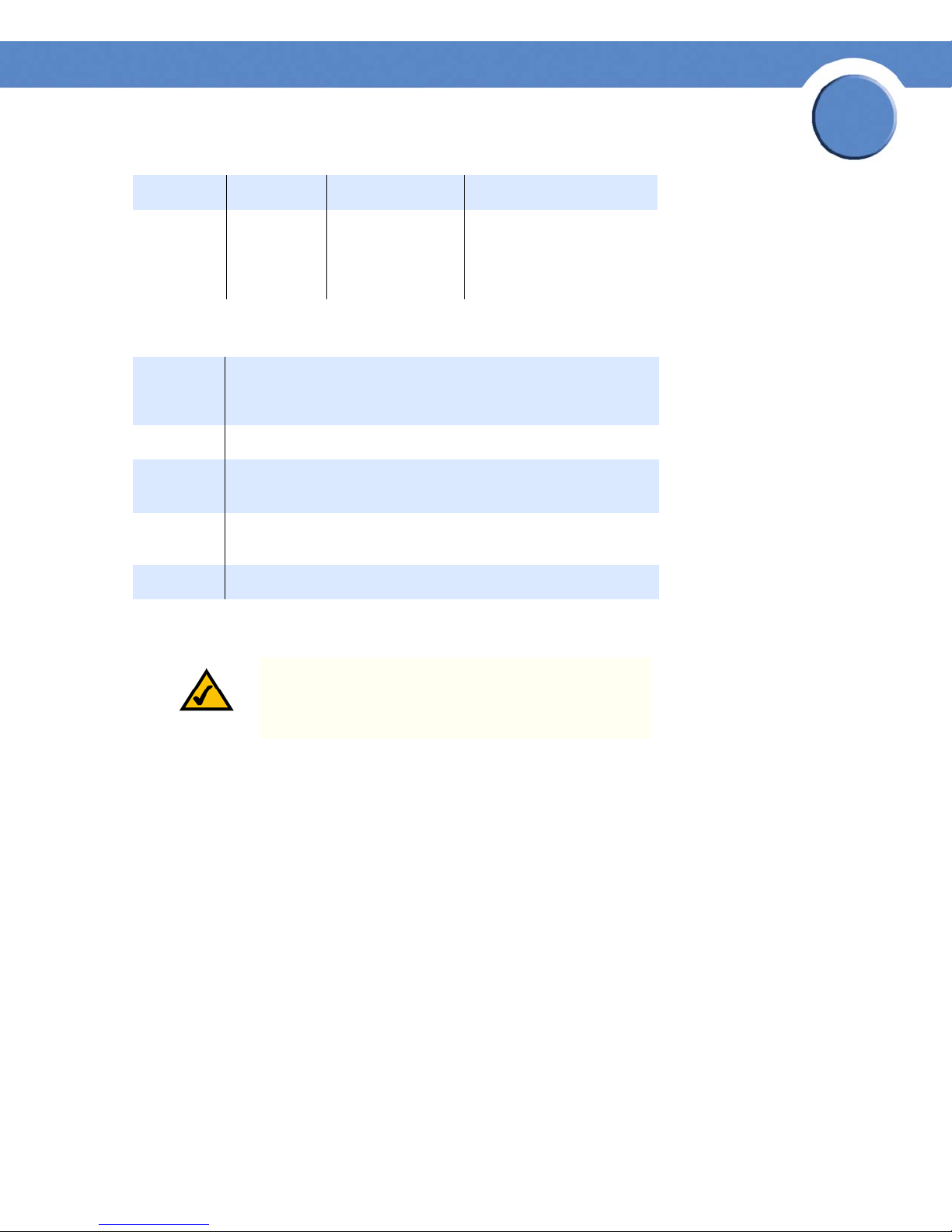
LED Off Green Amber
STBY/
ACTIVE
DC The
TEMP The
The
RPS1000 is
not powered
up.
RPS1000 is
not powered
up.
RPS1000 is
not powered
up.
The RPS1000 is in
active mode and
available to backup a failed
device.
The RPS1000
internal power
supplies are up
and running.
The RPS1000
internal
temperature is in
the acceptable
range.
(Blinking) The RPS1000 is
in standby mode. You can
connect devices to the
RPS1000, and it does not
attempt to back them up
until you press the STBY/
ACTIVE button and place
the RPS1000 into active
mode.
The DC output power is
not functioning correctly.
The RPS1000 is
approaching an overtemperature condition.
Chapter 2: Product Overview
Front-Panel Description
5
RPS1000—Business Series 380W RPS Unit Installation & Administration
LED Off Green Amber
Chapter
2
FAN The
RPS1000 is
not powered
up.
The fan is
running.
The fan is not operating
properly.
STBY/ACTIVE Button
Color DC Output Status
Off No device is connected to the output connector.
Green A device is connected to the output connector.
Blinking
green
Blinking
amber
Amber The RPS1000 is in standby mode or in a fault condition.
The RPS1000 has a front panel STBY/ACTIVE button.
The RPS1000 is unavailable to the connected device. The
RPS1000 is providing power to another connected device.
The RPS1000 is providing power to the connected device; the
output is active.
NOTE: The RPS1000 is in active mode (STBY/ACTIVE
LED green) when it powers up. It must be in standby
mode every time you connect devices to it.
If you connect a device to the RPS1000 when it is in active mode (STBY/ACTIVE LED green), the
RPS1000 might unnecessarily begin supplying backup power to the device. This situation might
occur if you connect the device before it is powered up, or if the RPS1000 does not immediately
sense that the device power supply was supplying power. In this case, the RPS1000 would not be
available as a backup power source for other connected devices.
Press the STBY/ACTIVE button to change the RPS1000 from active mode to standby mode when you
connect devices. When you change the mode to active, the STBY/ACTIVE LED turns green.
Chapter 2: Product Overview
Front-Panel Description
6
 Loading...