

Page 1
ProConnect®II Series
2224 Layer 2 Management
24-Port 10/100 Ethernet
Switch
Use this guide to install:
PC22224
User Guide
Page 2

COPYRIGHT & TRADEMARKS
Copyright © 2002 Linksys, All Rights Reserved. EtherFast is a registered trademark of
Linksys. Microsoft, Windows, and the Windows logo are registered trademarks of
Microsoft Corporation. All other trademarks and brand names are the property of their
respective proprietors.
LIMITED WARRANTY
Linksys guarantees that every ProConnect II 2224 Layer 2 Management 24-Port 10/100
Ethernet Switch is free from physical defects in material and workmanship under normal use for FIVE years from the date of purchase. If the product proves defective during this warranty period, call Linksys Customer Support in order to obtain a Return
Authorization Number. BE SURE TO HAVE YOUR PROOF OF PURCHASE ON HAND
WHEN CALLING. RETURN REQUESTS CANNOT BE PROCESSED WITHOUT PROOF
OF PURCHASE. When returning a product, mark the Return Authorization Number
clearly on the outside of the package and include your original proof of purchase. All
customers outside of the United States of America and Canada shall be held responsible for shipping and handling charges.
IN NO EVENT SHALL LINKSYS’ LIABILITY EXCEED THE PRICE PAID FOR THE PRODUCT FROM DIRECT, INDIRECT, SPECIAL, INCIDENTAL, OR CONSEQUENTIAL DAMAGES RESULTING FROM THE USE OF THE PRODUCT, ITS ACCOMPANYING SOFTWARE, OR ITS DOCUMENTATION. LINKSYS DOES NOT ISSUE REFUNDS. WARRANTY DOES NOT COVER NATURAL DISASTERS OR ACTS OF NATURE.
Linksys makes no warranty or representation, expressed, implied, or statutory, with
respect to its products or the contents or use of this documentation and all accompanying software, and specifically disclaims its quality, performance, merchantability, or
fitness for any particular purpose. Linksys reserves the right to revise or update its
products, software, or documentation without obligation to notify any individual or entity.
Please direct all inquiries to:
Linksys P.O. Box 18558, Irvine, CA 92623.
FCC STATEMENT
The ProConnect II 2224 Layer 2 Management 24-Port 10/100 Ethernet Switch has been
tested and found to comply with the limits for a Class A digital device, pursuant to Part
15 of the FCC Rules. These limits are designed to provide reasonable protection
against harmful interference in a residential installation. This equipment generates,
uses, and can radiate radio frequency energy and, if not installed and used according
to the instructions, may cause harmful interference to radio communications. However,
there is no guarantee that interference will not occur in a particular installation. If this
equipment does cause harmful interference to radio or television reception, which is
found by turning the equipment off and on, the user is encouraged to try to correct the
interference by one or more of the following measures:
• Reorient or relocate the receiving antenna
• Increase the separation between the equipment or device
• Connect the equipment to an outlet other than the receiver’s
• Consult a dealer or an experienced radio/TV technician for assistance
UG-PC22224-101102NC BW
Page 3

Returning to the Basic Management Screen 19
LAN Port Configuration 20
Changing the Speed and Flow Control 20
Setting the Line Speed 21
Changing the Flow Control 22
Displaying Physical Port Address 22
Returning to the Basic Management Screen 23
Console Port Configuration 23
Changing the Console Baud Rate 24
Selecting a Flow Control Method 24
Enabling or Disabling Modem Control Options 25
Specifying a Modem Setup String 26
Enabling or Disabling SLIP 26
Specifying a SLIP Address 26
Specifying a SLIP Subnet Mask 27
Returning to the Basic Management Screen 27
Advanced Management Activities 28
Switching Database Configuration 29
VLAN & PVID Perspective 30
Default VLAN 30
Obtaining a VLAN Perspective 30
Creating a New VLAN 31
Adding New Switch Ports 32
Deleting a VLAN ID 34
Viewing VLAN Activities 35
Searching for MAC Addresses 36
Obtaining Additional Information 36
Scrolling Thr ough Domains 36
Exiting the VLAN Screens 37
Viewing VLAN Settings 37
Adding Ports 38
Deleting Ports 39
Configuring PVID 40
IP Multicast Group Perspective 41
MAC Address Perspective 42
Port Perspective 43
Per Port VLAN Activities 43
Scrolling Thr ough MAC Addr esses 44
Per Port Statistics 45
IP Networking 47
IP & RIP Settings 48
ProConnect II
®
Series
Table of Contents
Introduction 1
Getting to Know the Switch 2
LEDs 2
The RJ-45 Ports 3
The Gigabit Expansion Ports 3
The Console Port 3
The Back Panel 4
Installing the Switch 5
Pre-Installation Considerations 5
Desk Top or Shelf Mounting the Switch 6
Rack-Mounting the Switch 6
Powering on and Resetting the Switch 7
Power On Self Test 7
Uplinking the Switch 8
Installing the Gigabit Expansion Modules 8
Switch Management 9
Overview 9
Local Console Management 9
Remote Console Management 10
SNMP Management 10
Assigning an IP Address to the Switch 10
Configuring the Switch 11
Overview 11
Web-Based Configuration and Management 11
Logging On to the Switch 11
Basic Management Activities 12
General Management Configuration 13
Changing the System Name 13
Changing the Location 14
Changing the Administration Password 15
Changing the Guest Password 16
Statistic Collection 17
Reboot-on-Error 18
Remote Telnet Login 18
2224 Layer 2 Management 24-Port 10/100 Ethernet Switch
n
nect II 2224
Page 4

Linksys EtherFast®II Series
ARP T ab le Settings 49
Adding Static ARP Tab le Entries 49
Deleting Static ARP Table Entries 51
Searching for ARP Table Entries 51
Routing T ab le 52
Adding Router Table Entries 53
Deleting Router Table Entries 54
Searching for Router Tsble Entries 55
DHCP Gateway Settings 55
Ping Settings 59
Bridging 61
Static Filtering 62
Spanning Tree Functions 63
Spanning Tr ee P ort Configuration 63
Spanning Tree Port States 65
Spanning Tree Path Costs 67
Spanning Tree Port Priorities 68
SNMP Functions 69
Stacking 72
Other Protocols 76
Port Trunking 77
Port Mirroring 79
Setting Quality of Service Parameters 81
SNMP and RMON Management 108
Overview 108
SNMP Agent and MIB-2 (RFC 1213) 108
RMON MIB (RFC 1757) and Bridge MIB (RFC 1493) 109
RMON Groups Supported 109
Bridge Group s Supported 110
Appendix 111
About Fast Ethernet 111
About Gigabit Ethernet 112
Fiber Optic Cabling 112
Twisted-Pair Cabling 113
Crimping Your Own Network Cables 114
Specifications 115
Customer Support 116
2224 Layer 2 Management 24-Port 10/100 Ethernet Switch
n
nect II 2224
Introduction
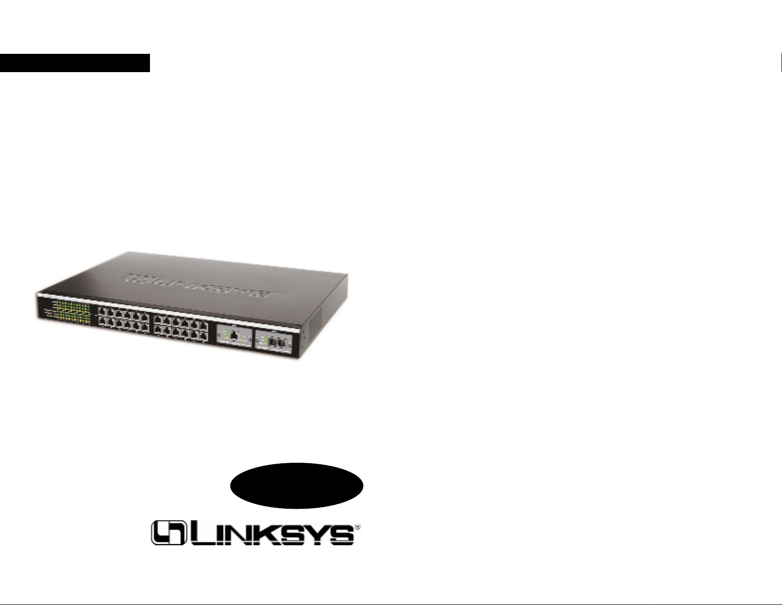
Maximize your network potential with this high-speed, high-reliability, manageable and stackable switch. The ProConnect® II 2224 Ethernet Switch
from Linksys delivers a combination of wire-speed Ethernet, Fast Ethernet,
and Gigabit solutions, all in one surprisingly affordable package. Perfect for
demanding enterprise environments, this switch's intelligent design and builtin SNMP provide maximum network control, regulating traffic and eliminating server bottlenecks. Its web browser-based management interface and
upgrade capability makes it ideal for busy network administrators. The
ProConnect II 2224 is rack mountable and includes two Expansion Slots that
accept optional Gigabit Modules (fiber or copper) to let you grow your network as your needs grow. Three Port Trunking groups eliminate bottlenecks,
and you can stack up to 8 switches and manage them as one. So when you're
ready to bring your network up to speed, get Linksys reliability, manageability, stackability, and expandability -- with the ProConnect® II 2224 Ethernet
Switch.
• 24 10/100 auto-MDI/MDI-X ports and 2 Gigabit Expansion Slots - speeds
up to 1000Mbps
• Optimizes your network traff ic with 802.1q VLAN support and 802.1p
traffic prioritization
• Stacking support for up to 8 switches lets your network grow
• Manageable via Console, Telnet, web browser, and SNMP/RMON
• 256K Packet Buffer and 32K MAC address entries
• IEEE 802.1Q VLAN support for up to 128 groups
• IGMP Multicast Filtering and Snooping
• Supports 3 Port Trunking groups that include up to 4 10/100 por ts and up
to 2 ports for the Gigabit modules
• IEEE 802.1d Spanning Tree support for redundant connections
1
ProConnect II 2224 Layer 2 Management 24-Port 10/100
Ethernet Switch
Page 5
2224 Layer 2 Management 24-Port 10/100 Ethernet Switch
n
nect II 2224
3
ProConnect II
®
Series
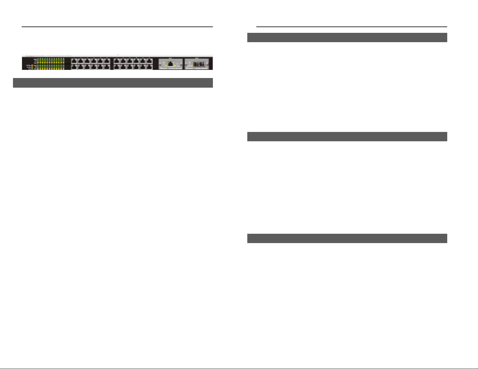
Getting to Know the Switch
Link/Act Green. Lights to indicate that the switch is successfully connect-
ing to the network. Blinks to indicate the switch is actively
receiving or sending the data over the port.
10/100 Green. Lights to indicate that the port is operating at 100 Mbps.
Off to indicate that he port is operating at 10 Mbps while the
switch is still working.
FDX/COL Amber. Lights to indicate that the port is operating in full-
duplex mode. Blinks to indicate that the connection is experiencing collisions.
Fan Red. Lights to indicate that the fans are not active.
TEMP Red. Lights to indicate that the switch exceeds its operational
temperature.
Power Green. Lights to indicate that the switch has power.
2
The Switch is equipped with twenty-four auto-sensing RJ-45 ports. These RJ45 ports support network speeds of either 10Mbps or 100Mbps, and can operate in half and full-duplex modes. Auto-sensing technology enables each port
to automatically detect the speed of the device connected to it (10Mbps or
100Mbps), and adjust its speed and duplex accordingly.
To connect a device to a port, you will need to use a network cable. You will
need to use Category 5 (or better) cable. For more information on twistedpair cabling, refer to the Twisted-Pair Cabling section.
The Switch is equipped with two expansion ports that provide for the installation of one or two expansion modules. These ports provide links to highspeed network segments or individual workstations at speeds of up to
1000Mbps (Gigabit Ethernet).
To establish a Gigabit Ethernet connection, you will need to install an SX or
TX Gigabit expansion module and use Category 5e cabling or fiber optic
cabling. for more information on fiber optic cabling, refer to the Fiber Optic
Cabling section.
The Switch is equipped with a serial port labeled CONSOLE (located on the
front of the switch) that allows you to connect to a computer’s serial port (for
configuration purposes) using the provided serial cable.
The Gigabit Expansion Ports
The Console Port
The RJ-45 Ports
LEDs
Page 6

2224 Layer 2 Management 24-Port 10/100 Ethernet Switch
n
nect II 2224
Installing the Switch
Fast Ethernet Considerations
If you will be using the Switch for Fast Ethernet (100Mbps) applications, you
must observe the following guidelines:
Full-Duplex Considerations
As previously mentioned, the Switch provides full-duplex support for its RJ45 ports. Full-duplex operation allows data to be sent and received simultaneously, doubling a port’s potential data throughput.
If you will be using the Switch in full-duplex mode, the maximum cable
length using Category 5 cable is 328 feet (100 meters).
Positioning the Switch
Before you choose a location for the Switch, observe the following guidelines:
• Make sure that the switch is accessible and that the cables can be connect-
ed easily.
• Keep cabling away from sources of electrical noise, power lines, and fluo-
rescent lighting fixtures.
• Position the Switch away from water and moisture sources.
• To ensure adequate air flow around the Switch, be sure to provide a mini-
mum clearance of two inches (50 mm).
• Do not stack free-standing Switches more than four units high.
5
ProConnect II
®
Series
Power Where the AC power cord connects.
FAN Radiates the heat inside the system.
Buzzer Warns you if the system overheats. To disable the warn-
ing system, use a pen point or similar object to push in
the button and the buzzer will not sound if the system
overheats.
4
Pre-Installation Considerations
The Back Panel
Page 7

2224 Layer 2 Management 24-Port 10/100 Ethernet Switch
n
nect II 2224
7
ProConnect II
®
Series
1. Place the Switch on a desktop or shelf near an AC power source and following the guidelines of the preceding paragraph, Positioning the Switch.
2. Connect one end of a standard network cable to one of the 10/100 RJ-45
ports on the front of the Switch.
3. Connect the other end of the cable to the network device, such as printer
server, workstation or router.
4. Connect one end of the power cable to the switch and the other end into a
standard electrical outlet. When the Switch receives power, the Power
LED will remain solid Green.
The installation is complete.
The Switch can be installed in a standard 19-inch rack.
Before you begin, disconnect all cables from the Switch.
1. Place the Switch right side up and with the front panel facing you.
2. Position a mounting bracket over the screw holes on one side of the
Switch.
3. Secure the mounting bracket by inserting a screw into each of the three
screw holes. Use a screwdriver to tighten the screws, ensuring that they
are fastened f irmly in place.
4. Repeat steps 2 and 3 to install the other mounting bracket on the opposite
side of the Switch.
5. Insert the Switch into the 19-inch rack and secure it with suitable screws
(not provided). Ensure that the ventilation holes are not obstructed.
The rack-mount installation is complete.
You can now re-connect the cables to the back of the Switch.
6
To power on the Switch, simply connect the power cord to the back of the
Switch, then plug the power cord into an electrical outlet. The Switch will
boot up within approximately 30 seconds.
If you need to reset the Switch, remove the power cord from the back of the
Switch and then reconnect it.
When you power-on the switch, it performs a Power-On Self Test (POST).
During the POST, the Switch’s CPU:
• Performs a series of diagnostic procedures to make sure the basic system
is functioning with integrity.
• Decompresses the main switching software run-time image from the flash
ROM into DRAM area.
• Begins executing the main switching software. During the POST process
if the Esc key is pressed, a COMMAND LINE prompt appears.
Download Runtime This option downloads the runtime system image to
Software from the Switch through the Switch's Console port. Before
Console Port you select this option, make sure:
• A host system is running a terminal emulation
program that supports the Kermit f ile transfer
protocol.
• The host system's hard drive has the required binary f ile that will be downloaded to the switch.
Configure the System This option lets you modify any conf igurable parame-
ter in the switch's flash ROM before the switch system boots.
Run Manufacturing This option downloads the manufacturer's diagnos
Diagnostics tics. This option has the same download requirements
as the runtime software applied. When the file transfer is completed, the target system jumps to the entry
point of the diagnostic program and starts executing
the diagnostic code. The Main Menu of the diagnostic
program appears, where you can initiate tests or
obtain system information. Note that user intervention is not required when a test runs, unless an error
occurs. If an error occurs during testing, you are
given the choice of continuing the diagnostics or
skipping the error.
Powering On and Resetting the Switch
Power On Self Test
Rack-Mounting the Switch
Desk Top or Shelf Mounting the Switch
Page 8

2224 Layer 2 Management 24-Port 10/100 Ethernet Switch
n
nect II 2224
Switch Management
The Switch offers an easy-to-use, menu-driven console interface. Using this
interface, you can perform various switch configuration and management
activities, including:
• Configuring system and por t parameters
• Assigning an IP address to the Switch
• Configuring routing proper ties
• Configuring ARP
• Configuring DHCP
• Setting VLAN policies
• Setting packet filtration
• Configuring STP and SNMP parameters
• Upgrading f ir mware
There are four methods of managing the Switch:
• Local Console Management using the serial port
• Remote Console Management using telnet
• Using an SNMP Management Station
• Web-Browser
Local Console Management
You can manage the Switch locally by connecting the switch to a PC or workstation with terminal emulation software, such as Hyperterminal, using the
serial port.
Before you log on to the Switch, make sure that the Switch’s Console port
settings are as follows:
BAUD RATE: 115200
FLOW: None
PARITY: None
STOP BITS: 1
DATA BITS: 8
EMULATION: ANSI
CURSOR EMULATION: VT100
9
ProConnect II
®
Series
All 24 ports on the Switch can act as uplink ports, allowing you to uplink to
other switches or hubs using a standard Ethernet connection.
To uplink the switch, connect one end of a Category 5 (or better) network
cable into a port, then connect the other end of the cable into the desired network device’s uplink port. MDI/MDIX will automatically detect the speed and
cable type.
Use the following instructions to install the Gigabit Expansion Modules:
Before you begin power off the Switch by disconnecting all cables from the
Switch.
1. Place the Switch right side up, with the front panel facing you.
2. Use a screwdriver to remove the desired Expansion Module cover plate
(labeled “Module 1” and “Module 2”). Set the screws aside for step 4.
3. Insert the Gigabit Expansion Module (must be purchased separately) into
the selected Gigabit Expansion Port, ensuring that it is seated firmly in
place.
4. Secure the module in place using the screws and a screwdriver.
The Gigabit Expansion Module installation is complete.
You can now re-connect the cables to the back of the Switch.
EFPC2GE - Gigabit Ethernet
EFPC2SC - Gigabit Fiber Optic
8
Overview
Uplinking the Switch
Installing the Gigabit Expansion Modules
Page 9

2224 Layer 2 Management 24-Port 10/100 Ethernet Switch
n
nect II 2224
Configuring the Switch
The Switch features a menu-driven console interface for switch configuration. The Switch can be configured locally through the console port using a
terminal emulation software, such as Hyperterminal, or remotely via a Telnet
connection.
This User Guide provides instructions on how to configure and manage the
Switch using the console
interface. If you wish to manage the switch through
a web connection, you can do so by connecting to the Switch’s IP Address
using your web browser.
Although the web-based management menu will differ in appearance from
the console-based management menu, you will still have access to all the
same configuration and management features.
When logging on to the Switch, you will receive the following screen prompt:
Linksys Switch
Screen Name:
System Name: PC22224
Console Login:admin
Password:
Enter the default login and password, pressing Enter after each entry (as
shown in the image below).
11
ProConnect II
®
Series
Remote Console Management
You can manage the Switch remotely by having a remote host establish a
Telnet connection to the switch via an Ethernet or modem link.
To use this management method:
• The host must run a SLIP protocol if a modem is used
• The Switch must have an IP address
• Remote Telnet Login must be enabled on the Switch.
The Remote Console Management interface is identical in appearance and
functionality to the Local Console Management interface. If you are using
Microsoft’s Telnet, the terminal setting should be set to VT100/ANSI.
SNMP Management
You can manage the Switch across a LAN using an SNMP Network
Management Station with a graphical user interface. This management
method allows you to monitor statistical counters and set switch parameters
from the remote Network Management Station.
To use this management method:
• The network must use the IP protocol
• The Switch must be configured on the network with a proper IP address
• SNMP must be enabled on the Switch.
Assigning an IP Address to the Switch
To manage the Switch remotely through the console port or with an SNMP
Management Station, you must assign an IP address to the Switch. To assign
an IP address to the Switch, refer to the Configuring the Switch section.
Logging On to the Switch
When you log on to the Switch for the first time, a sign-in string appears and
you are prompted for a console login name and password. The factory default
login name is set as “admin” and the password is blank. You can create a
password after you log on.
10
Overview
Web-Based Configuration and Management
Logging On to the Switch
Page 10
2224 Layer 2 Management 24-Port 10/100 Ethernet Switch
n
nect II 2224
• General allows to you change the system name, contact, location, admin-
istration and guest passwords, statistics collection, reboot-on-error, remote
Telnet login, and remote HTTP login.
• LAN Port allows you to configure line speed and flow control, Admin
Control, and view the physical address of the Switch.
• Console Port allows you to change the console baud rate, flow control
method, modem control, and setup string; enable or disable SLIP; and configure the SLIP address and SLIP subnet mask.
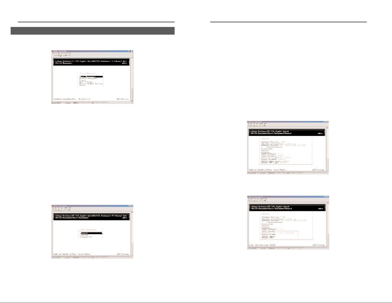
General Management Configuration
Select General from the Basic Management screen. The General screen will
appear with the System Name highlighted.
Use the following procedure to configure the general management options:
Changing the System Name
1. From the General screen, highlight System Name and press the Enter key.
The Enter System Name screen appears.
13
ProConnect II
®
Series
12
After you log on to the Switch, the Switch Management screen will appear.
The Switch Management screen consists of a series of menus. Each menu
has several options, which are listed vertically. A highlight in each menu lets
you select the option you wish to choose; pressing the Enter key activates the
highlighted option.
To navigate through the Console Interface use the Up Arrow or Down Arr ow
keys to move up or down, use the Enter key to select, and the Esc key to
return to the previous selection; menu options and any values entered or present will get highlighted. Note that the bottom of the window always has a listing of the appropriate key strokes.
Basic management activities consist of General, LAN port, and console port
tasks. To perform basic management activities:
1. From the Switch Management screen, highlight Basic Management and
press Enter. The Basic Management screen will appear.
2. From the Basic Management screen, highlight the desired option and
press the Enter key:
Basic Management Activities
Page 11
2224 Layer 2 Management 24-Port 10/100 Ethernet Switch
n
nect II 2224
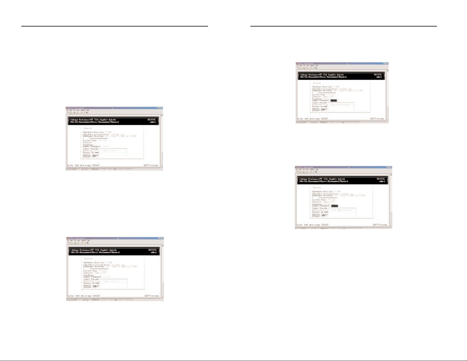
Changing the Administration Password
1. Use the Down Arro w key to highlight admin Password and press the
Enter key. The Enter Old Password screen will appear.
2. Enter the current password. Each character you type appears as an aster-
isk (*). If you make a mistake, use the Backspace key to delete the error.
3. Press Enter. The Enter New Password screen will appear.
4. Enter the new password. For security, each password character you type
appears as an asterisk (*). The password is case-sensitive, can be no more
than 16 characters (only alphanumeric characters and the underscore “_”
character can be used).
15
ProConnect II
®
Series
14
2. Enter a system name (16 characters max.). If you make a mistake, use the
Backspace key to delete the error.
3. Press Enter to return to the General screen.
Changing the Contact
To change the contact:
1. From the General screen, highlight Contact and press the Enter key. The
Enter Contact screen appears.
2. Enter a contact name. If you make mistakes, use the Backspace key to
delete the error.
3. Press the Enter key to return to the General screen.
Changing the Location
1. From the General screen, move the cursor to Location and press the
Enter key . The Enter Location screen will appear.
2. Enter a location name. If you make a mistake, use the Backspace key to
delete the error.
3. Press Enter to return to the General screen.
Page 12
2224 Layer 2 Management 24-Port 10/100 Ethernet Switch
n
nect II 2224
2. Enter a new guest password. If you make a mistake, use the Backspace
key to delete the error. The password is case-sensitive, can be no more
than 16 characters (only alphanumeric characters and the underscore “_”
character can be used).
3. Press Enter to return to the General screen.
Statistic Collection
1. From the General screen, highlight Statistic Collection and press the
Enter key. The following screen will appear.
2. Highlight one of the following choices:
Disabled (prevents active statistic collection for each port)
Enabled (allows active statistic collection for each port)
3. Press Enter to return to the General screen.
17
ProConnect II
®
Series
5. Press Enter. A screen will prompt you to re-enter the new password.
6. Re-enter the new password you typed in step 4 and press Enter. The
Password Changed message will appear, confirming that the new password is in effect.
7. Press Enter to remove the message and return to the General screen. The
admin password will appear as asterisks in the admin Password field.
Changing the Guest Password
1. Use the Down Arro w key to highlight guest Password and press the Enter
key. The Enter New Password screen will appear.
16
Page 13
2224 Layer 2 Management 24-Port 10/100 Ethernet Switch
n
nect II 2224
19
ProConnect II
®
Series
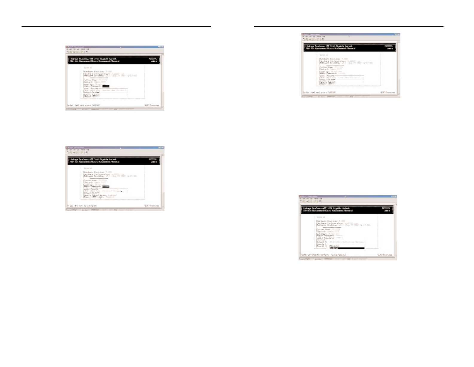
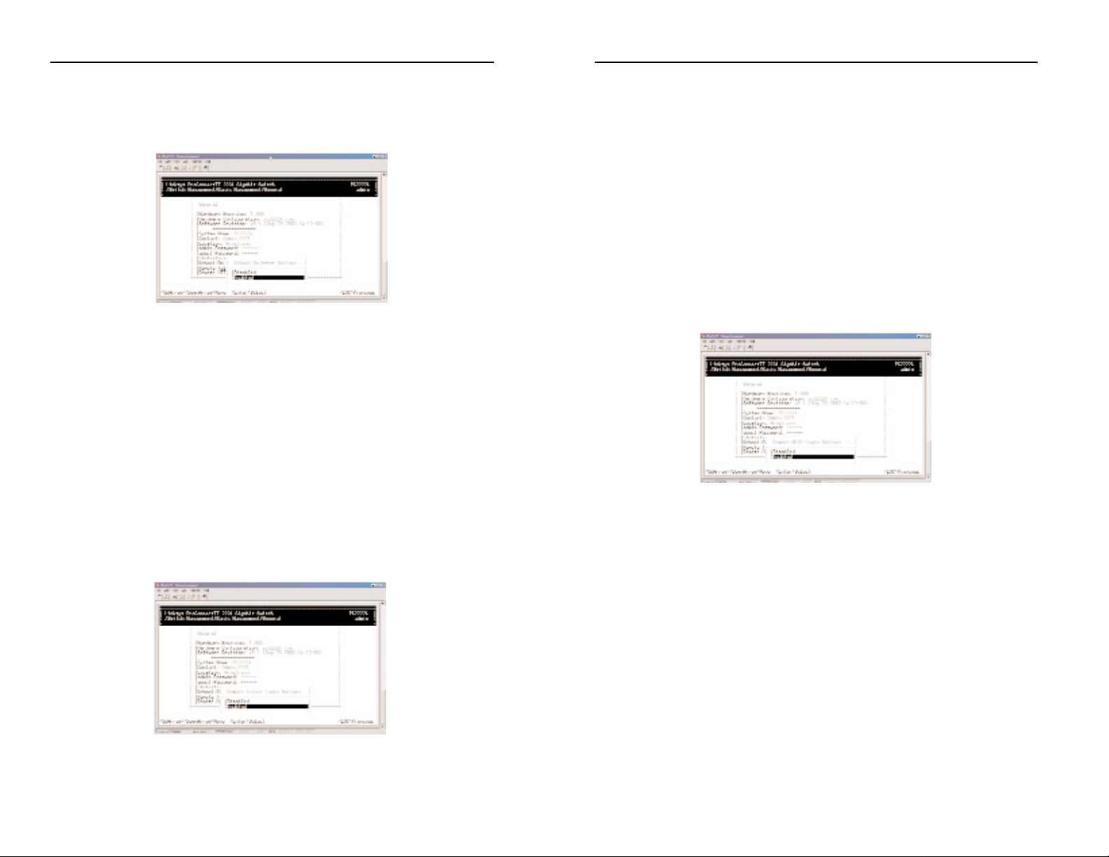
Reboot-on-Error
1. From the General screen, highlight Reboot-On-Error and press the Enter
key. The following screen will appear.
2. Highlight one of the following choices:
Disabled (prevents the Switch from automatically resetting when a
fatal error is detected. This setting is useful when a persistent problem needs to be reported)
Enabled (allows the Switch to automatically reset when a fatal error
is detected)
3. Press Enter to return to the General screen.
Remote T elnet Login
1. From the General screen, highlight Remote Telnet Login and press the
Enter key. The following screen will appear.
18
2. Highlight one of the following choices:
Disabled (prevents remote Telnet logins to the Switch)
Enabled (allows remote Telnet logins to the Switch. This is the
default setting)
3. Press Enter to return to the General screen.
Remote Http Login
To enable or disable the function of Remote Http Login:
1. From the General screen, highlight Remote Http Login and press the
Enter key. The following screen will appear:
2. Highlight one of the following choices:
Disable prevents remote HTTP login to the switch.
Enable allows remote HTTP login to the switch.
3. Press the Enter key to go back to the General screen.
Returning to the Basic Management Screen
After completing the general management activities, press the Esc key to exit
the General screen and return to the Basic Management screen. Y ou can then
select another option from the Basic Management screen or press Esc to
return to the Switch Management screen.
Page 14
2224 Layer 2 Management 24-Port 10/100 Ethernet Switch
n
nect II 2224
3. Proceed to the appropriate section:
To set the line speed, proceed to the Setting the Line Speed section
To set the flow control, go to the section on Changing the Flow
Control.
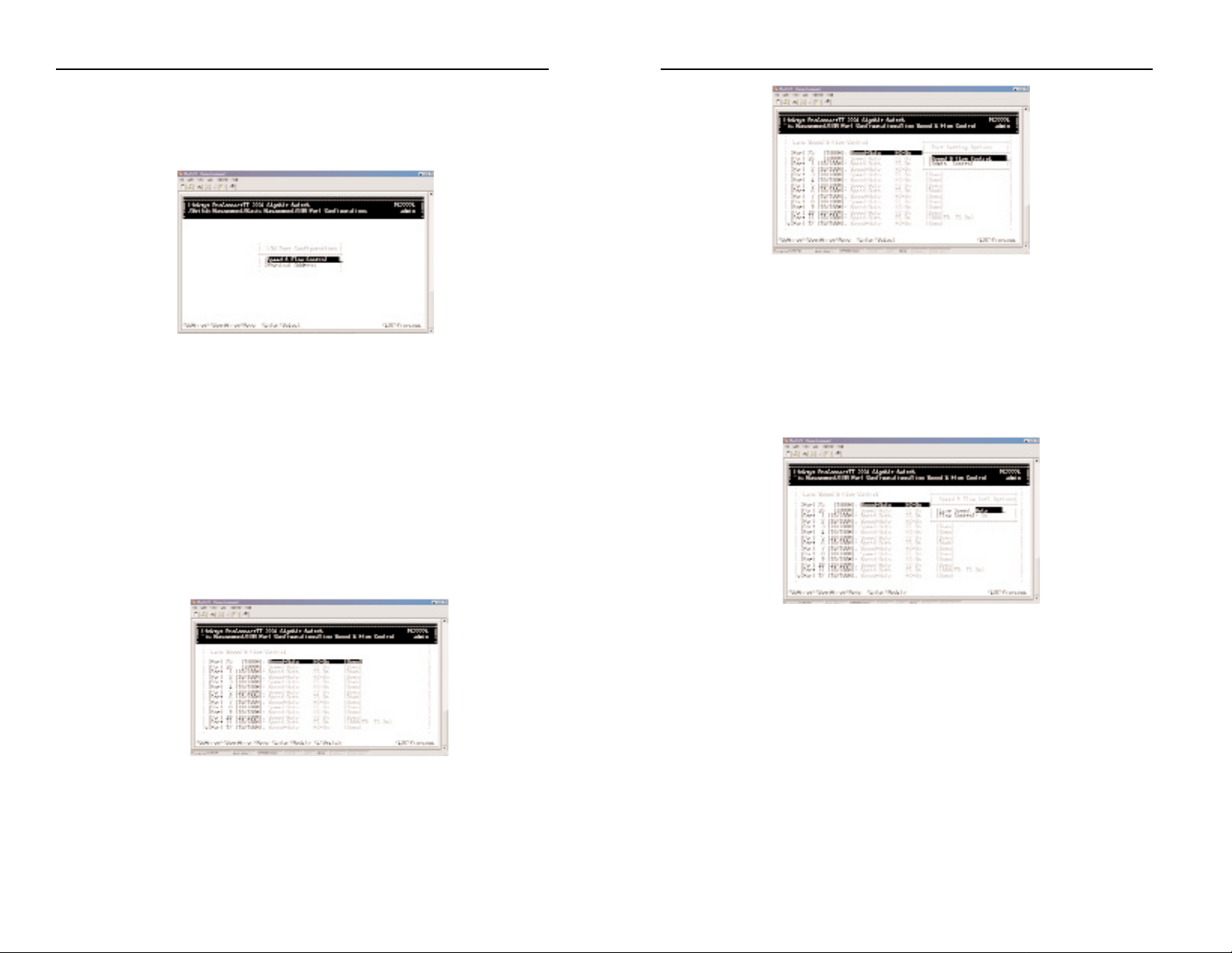
Setting the Line Speed
1. Press Enter with the Speed & Flow Control value highlighted . The Speed
& Flow Control Options menu will appear.
2. Highlight the line Speed Option you want to select for the port. Auto
allows the Switch to automatically determine the line speed and duplex
mode. All the other selections force the Switch to use a specific line
speed and duplex mode.
3. Press Enter. You will retur n to the Speed & Flow Cntl Options screen and
the line speed setting you selected appears next to Line Speed.
4. To configure the flow control for this port, proceed to Changing the
Flow Control.
5. To configure the line speed for additional por ts, press Esc to remove the
Speed & Flow Cntl Options screen. Then highlight the port you want to
configure and repeat steps 1 through 4.
6. When you finish, press the Esc key from the Line Speed & Flow Control
screen to return to the LAN Port Configurations screen.
21
ProConnect II
®
Series
LAN Port Configuration
Select LAN Port from the Basic Management screen. The LAN Port
Configurations screen will appear, with Speed & Flow Control highlighted.
Use the procedures in this section to configure the LAN Port Configuration
options for one or more ports, including:
• Speed & Flow Control
• Administration Control
• Physical Address
Changing the Speed and Flow Control
1. From the LAN Port Configurations screen, highlight Speed & Flow
Control and press the Enter key. A screen similar to the following will
show the current line speed settings for all ports. If an expansion module
is installed in the switch, it will also be listed.
2. You conf igure each port individually. To conf igure an individual port,
highlight it and press Enter. The Port Setting Options screen will appear
20
Page 15
2224 Layer 2 Management 24-Port 10/100 Ethernet Switch
n
nect II 2224
23
ProConnect II
®
Series
22
Returning to the Basic Management Screen
After completing the general management activities, press the Esc key to exit
the General screen and return to the Basic Management screen. Y ou can then
select another option from the Basic Management screen or press Esc to
return to the Switch Management screen.
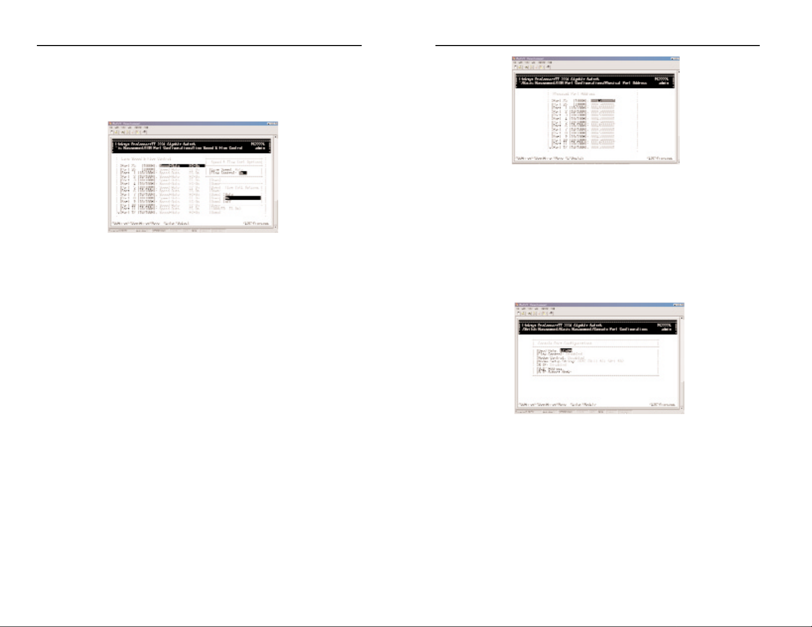
Console Port Configuration
Select Console Port from the Basic Management screen, the Console Port
Configurations screen will appear, with the Baud Rate value highlighted.
Use the procedures in this section to configure the Console Port
Configurations options for one or more settings, including:
• Specifying Baud Rate
• Specifying Flow Control
• Enable or Disable Modem Control
• Enter Modem Setup String
• Enable or Disable SLIP
• Specify a Slip Address
• Specify a SLIP Subnet Mask
Changing the Flow Control
1. With the Speed & Flow Cntl Options screen displayed, press the Down
Arrow key to highlight Flow Control and press Enter. The Flow Cntl
Options screen will appear.
2. Highlight the desired flow control option for the port. Auto allows the
Switch to automatically determine whether or not to use flow control. On
enables flow control at all times. Off disables flow control at all times.
3. Press Enter. You will retur n to the Speed & Flow Cntl Options screen,
and the selected flow control setting will appear next to Flow Control.
4. To configure the flow control for additional ports, press Esc to remove
the Speed & Flow Cntl Options screen. Highlight the desired port then
press Enter. Highlight Speed and Flow Control, then press Enter. Repeat
steps 1 through 3 for each additional port.
5. When you are finished, press the Esc key from the Line Speed & Flow
Control screen to return to the LAN Port Configurations screen.
Admin Control
1. From the Port Settings Options menu, select Admin Control and press
the Enter key.
2. The Admin Status Options menu will appear.
3. Select Up to allow administration of the Switch per port or Down to disallow.
Displaying Physical Port Address
The following procedure describes how to display the physical address of the Switch.
1. From the LAN Port Configur ationsscreen, highlightPhysical Address and press
the Enter key. A screen similar to the following (see next page) will appear.
Page 16

2224 Layer 2 Management 24-Port 10/100 Ethernet Switch
n
nect II 2224
Enabling or Disabling Modem Control Options
1. From the Console Port Configurations screen, highlight Modem Control
and press the Enter key. A screen similar to the following will show
whether a console modem connection is enabled or disabled.
2. Highlight Enabled or Disabled in the Modem Control Options f ield to
either enable or disable a modem connection to the console port.
3. Press Enter. You will retur n to the Console Port Configurations screen
and the modem control option you selected will appear in the Modem
Control field.
Specifying a Modem Setup String
If you enabled a modem connection to the console port, use the following
procedure to specify a modem setup string.
1. From the Console Port Configurations screen, highlight Modem Setup
String and press the Enter key. A screen similar to the following will
show the current modem setup string option.
2. Highlight the desired modem setup string option.
25
ProConnect II
®
Series
24
NNoottee::
Switch setup, when accessed through a modem or
SLIP account, is the sole responsibility of the user. Technical
support is not provided for setup of modem or SLIP.
Changing the Console Baud Rate
1. From the Console Port Configurations screen, highlight Baud Rate and
press the Enter key. A screen similar to the following will show the current console baud rate.
2. Highlight the baud rate you want to select for the console. Auto allows the
Switch to autosense the baud rate between 9600 bps and 115,200 bps. If
you choose Auto, it will choose the rest of your configuration selections.
Then, when you exit the configuration program, press the Enter key one
or more times until the prompt Linksys Switch Login Password appears on
your computer screen. All other selections force a specif ic console baud
rate.
3. Press Enter. You will retur n to the Console Port Configurations screen
and the selected console port baud rate will appear in the Baud Rate field.
Selecting a Flow Control Method
1. From the Console Port Configurations screen, highlight Flow Control and
press the Enter key. A screen similar to the following will show the cur-
rent console flow
control method.
2. Highlight the desired flow control method for the console and press
Enter. You will retur n to the Console Port Configurations screen and the
selected flow control method will appear in the Flow Control field.
Page 17
2224 Layer 2 Management 24-Port 10/100 Ethernet Switch
n
nect II 2224
27
ProConnect II
®
Series
3. Press the Enter key. If you highlight Default Setup String, you will return
to the Console Port Configurations screen and the default modem string
will appear in the Modem Setup String f ield. If you highlight Custom
Setup String, enter the custom string in the Enter Modem Setup String
screen and press Enter again. You will retur n to the Console Port
Configurations screen and the custom setup string will appear in the
Modem Setup String field.
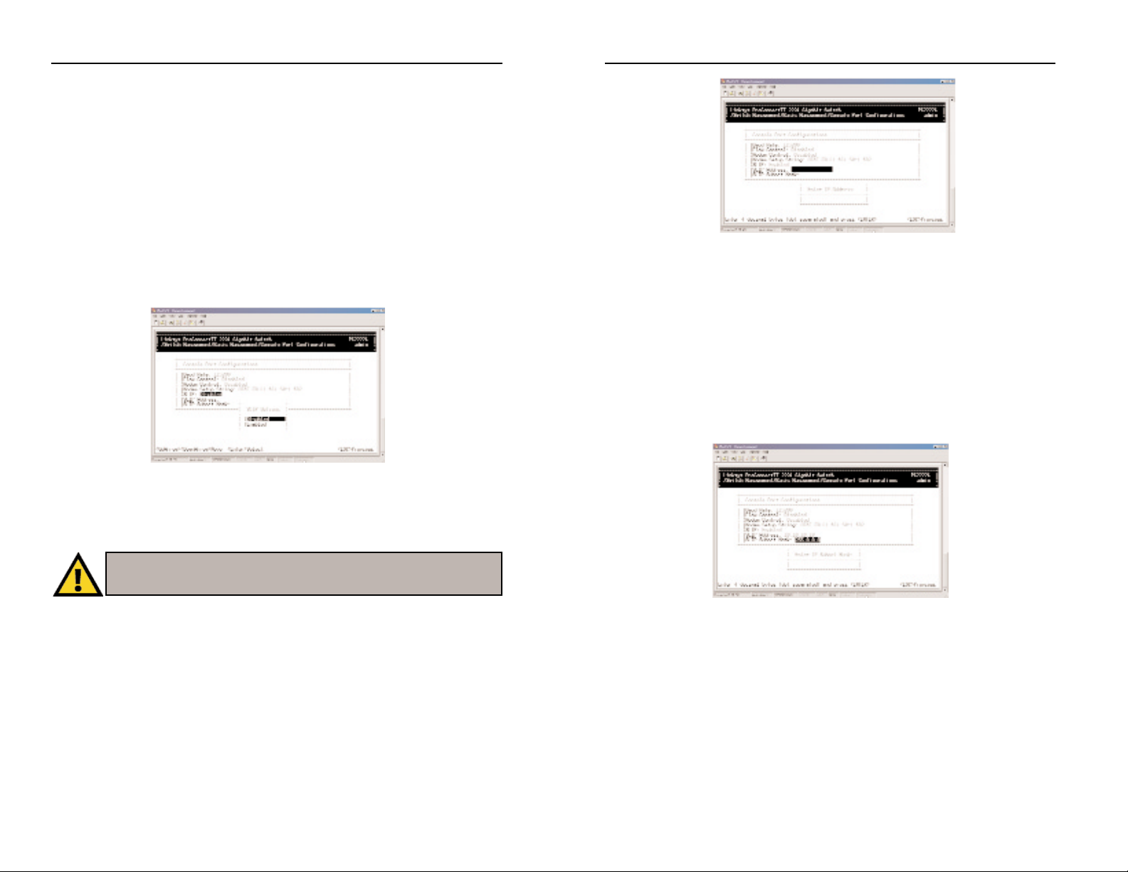
Enabling or Disabling SLIP
1. From the Console Port Configurations screen, highlight SLIP and press
the Enter key. A screen similar to the following will show the current
SLIP setting.
2. Highlight Enabled or Disabled to either enable or disable SLIP, then press
Enter.You will return to the Console Port Configurations screen and the
selected SLIP option will appear in the SLIP field.
Specifying a SLIP Address
If you enabled SLIP, use the following procedure to enter an address that has
a network part different than the network address of the Switch (for more
information, contact your network administrator).
1. From the Console Port Configurations screen, highlight SLIP Address and
press Enter. The following screen (see next page) will appear.
26
2. Enter the SLIP address. The address consists of numbers separated by
periods (e.g., 192.168.1.105).
3. After you enter the SLIP address, press the Enter key. You will return to
the Console Port Configurations screen and your entry will appear in the
SLIP Address field.
Specifying a SLIP Subnet Mask
If you are using SLIP, enter a suitable SLIP subnet mask.
1. From the Console Port Configurations screen, highlight SLIP Subnet
Mask and press Enter. The Enter IP Subnet Mask screen will appear.
2. Enter the SLIP subnet mask. The subnet mask consists of numbers separated by periods (e.g., 255.255.255.0).
3. After you enter the SLIP subnet mask, press the Enter key. You will
return to the Console Port Configurations screen and your entry will
appear in the SLIP Subnet Mask field.
Returning to the Basic Management Screen
After completing the general management activities, press the Esc key to exit
the Console Port screen and return to the Basic Management screen. You can
then select another option from the Basic Management screen or press Esc to
return to the Switch Management screen.
NNoottee::
if you enable SLIP, a warning window will appear telling you to disable
SLIP if you encounter problems. By enabling SLIP, the switch cannot be
directly accessed through the console port with the provided serial cable.
Page 18
2224 Layer 2 Management 24-Port 10/100 Ethernet Switch
n
nect II 2224
• Other Protocols lets you view and change GVRP and IGMP settings.
• P ort T runking allows you to assign a range of ports to trunking groups.
• Port Mirroring lets you mirror one port to another.
• QoS Setup allows for the configuration of Quality of Service.
• File T ransfer allows you to upgrade your Switch software.
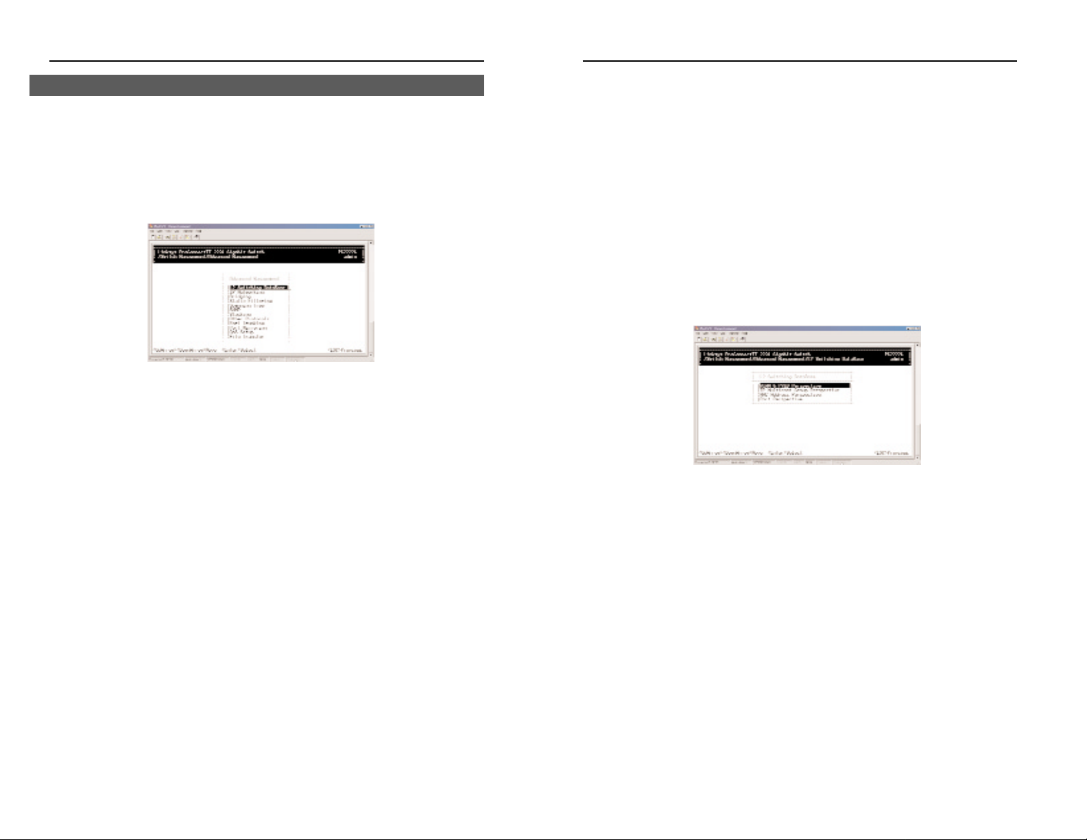
Switching Database Configuration
Select L2 Switching DataBase from the Advanced Management screen and
press Enter. The L2 Switching DataBase screen will appear, with VLAN &
PVID Perspective highlighted.
The Switch can be viewed from the four perspectives in the L2 Switching
DataBase screen.
• VLAN & PVID Perspective
• IP Multicast Group Perspective
• MAC Addr ess P erspective
• Port Perspective
These four views allow a network administrator to manage and monitor
VLANs and their associated MAC addresses and ports effectively from different views.
29
ProConnect II
®
Series
28
Advanced management activities consist of the Layer 2 switching database,
IP networking, Bridging, Static Filtering, Spanning Tree, SNMP, Stacking,
Other Protocols, Port Trunking, Port Mirroring, QOS Setup, and File Transfer.
To perform advanced management activities:
1. From the Switch Management screen, highlight Advanced Management
and press Enter. The Advanced Management screen will appear.
2. In the Advanced Management screen, highlight the desired option and
press the Enter key.
The following options are available:
• L2 Switching DataBase lets you view and change VLAN and PVID, IP
multicast group, MAC address, and Port Perspectives.
• IP Networking allows you to view or change IP settings, ARP and routing
table parameters, RIP parameters, DHCP gateway settings, and ping settings.
• Bridging lets you view and change the aging period for a MAC address
and set the Flood Limits for all ports.
• Static Filtering allows you to view, add, delete, or search all source or des-
tination addresses to be filtered.
• Spanning Tr ee lets you view and change parameters relating to the span-
ning tree protocol.
• SNMP allows you to view, enable, and change all SNMP-related information.
• Stacking allows you to set up the stack configuration.
Advanced Management Activities
Page 19

2224 Layer 2 Management 24-Port 10/100 Ethernet Switch
n
nect II 2224
Creating a New VLAN
1. From the VLAN Perspective screen in, hold down the Shift key and press
the “+” key . The New VLAN Settings screen will appear.
.
2. With the VLAN ID f ield highlighted, press the Enter key . The Enter New
VLAN ID screen will appear.
3. Enter a new VLAN ID as either a decimal or hexadecimal ID value from
1 to 4094 (0xFFE).
4. Press Enter. The VLAN ID appears next to VLAN ID in the New VLAN
Settings screen.
5. To enter an optional VLAN name, perform the following steps (the
VLAN name is used to identify the VLAN at the local switch).
a) Press the Down Arr o w key to move to VLAN Name.
b) Press Enter. The Enter New VLAN Name screen will appear.
31
ProConnect II
®
Series
30
VLAN & PVID PERSPECTIVE
This section describes the default VLAN and how to obtain a VLAN perspective.
Default VLAN
The IEEE 802.1Q standard defines VLAN ID #1 as the default VLAN. The
default VLAN includes all the ports as the factory default. The default
VLAN’s egress r ule restricts the por ts to be all untagged, so it can, by default,
be easily used as a simple 802.1D bridging domain. The default VLAN’s
domain shrinks as untagged ports are def ined in other VLANs.
Obtaining a VLAN Perspective
The following procedure describes how to obtain a VLAN perspective.
For convenience, the VLAN ID appears as both decimal and hexadecimal
values side by side in the VLAN Perspective screen.
1. From the L2 Switching DataBase screen, highlight VLAN & PVID
Perspective and press the Enter key. The VLAN & PVID Perspective
screen will appear. Select VLAN settings.
From this screen you will be able to:
• Create a new VLAN
• Delete a VLAN ID
• View VLAN activities
• View or change a VLAN Configuration
To return to the VLAN & PVID Perspective screen, press the Esc key.
Page 20

2224 Layer 2 Management 24-Port 10/100 Ethernet Switch
n
nect II 2224
If you highlight Tagged Ports, the screen window reads Select Tagged
Ports, as in the following screen.
3. In the Select Untagged Ports or Select Ta gged P orts screen, use the Up
Arrow and Down Arr o w keys to highlight an individual port.
4. Press Enter. An asterisk appears to the right of the selected port. Repeat
this step for each new port you want to add.
5. After selecting the new ports you want to add, press Esc. A screen will
show the selected ports and whether they are tagged or untagged.
6. If you added untagged ports and want to now add tagged ports, or vice
versa, repeat steps 1 through 4 and in step 2 select the appropriate port
option. To remove a port, highlight the desired port and press “-”.
33
ProConnect II
®
Series
c) Enter a name for the new VLAN (up to 31 alphanumeric characters).
d) Press Enter. The VLAN name appears next to VLAN Name in
the New VLAN Settings screen.
6. Press the Esc key. A screen similar to the following will appear.
This screen will allow you to add or delete switch port to a VLAN.
Adding New Switch Ports
To add new switch ports to the newly created VLAN:
1. Hold down the Shift key and press “+” to display the Port Options screen.
2. In the Port Options screen, highlight either Untagged Ports or Tagged
Ports and press the Enter key.If you highlight Untagged Ports, the screen
window reads Select Untagged Ports, as in the following screen. Ports not
allowed to be used in specif ic VLANs are labeled Forbidden Ports.
32
Page 21

2224 Layer 2 Management 24-Port 10/100 Ethernet Switch
n
nect II 2224
Viewing VLANActivities
The following procedure describes how to use the VLAN Perspective screen
to view activities for a particular VLAN. Using this procedure, you can view:
• Active ports.
• Active MAC addresses associated with a VLAN.
• A transient address, if any.
• Filtering and port information.
To view VLAN activities:
1. From the VLAN Perspective screen , highlight an existing VLAN and
press the Enter key.
2. TheVLAN Info screen appears, with the highlight on VLAN Activities.
Press the Enter key.
This screen shows all active MAC addresses and VLAN domains for the
VLAN you selected.
• MAC addresses are those that have been sending frames from this VLAN
to the switch within the last aging period.
• VLAN domain shows the domains in this VLAN from which active MAC
addresses have been learned within the last aging period.
You can use the Tab key to move between the MA C Addr esses and VLAN
Domain screens.
35
ProConnect II
®
Series
7. Press Esc to return to the VLAN Perspective screen. You may then select
another option from the VLAN Perspective screen or press Esc to return to
the L2 Switching DataBase screen.
The VLAN IDs and names you added will appear in the VLAN
Perspective screen. In the following screen, the Zuma and lana VLAN IDs
have been added.
Deleting a VLAN ID
Use the following procedure to delete a VLAN ID from the VLAN Perspective
field.
1. Use the Up Arro w and Down Arr o w keys to highlight the VLAN ID you
want to delete.
2. Press the “-” (hyphen) key. A message will ask whether you are sure you
want to delete the VLAN ID.
3. With Yes highlighted, press the Enter key to delete the VLAN ID, or to
retain it, press the Esc key or highlight No and press Enter.
34
Page 22

2224 Layer 2 Management 24-Port 10/100 Ethernet Switch
n
nect II 2224
Exiting the VLAN Screens
When you finish performing VLAN activities, press the Esc key until you
return to the desired screen.
Viewing VLAN Settings
Using the VLAN Configuration screen, you can view VLAN settings.
1. From theVLAN Perspective screen, highlight an existing VLAN and press
the Enter key. A screen similar to the following will appear, with the
high-light on VLAN Activities.
2. Press the Up Arro w or Down Arr o w key to highlight VLAN Settings.
3. Press Enter. A screen similar to the following will appear.
4. From this screen, you can add or delete switch ports from any VLAN
except the default VLAN. The controls for adding and deleting ports are
not displayed for the default VLAN.
37
ProConnect II
®
Series
Searching for MAC Addresses
To search for MAC addresses:
1. In the VLAN MAC Address screen, press S. The Enter MA C Addr To
Search screen will appear.
2. Enter a MAC address in the Enter MAC Addr T o Search screen and press
the Enter key. If the address is found, it is highlighted in the MAC
Addresses screen.
Obtaining Additional Information
To obtain additional information about an active MAC address:
1. In the MA C Addr esses screen, scroll to the desired address.
2. Press the Enter key . A VLAN/IP Multicast Group Membership screen
similar to the following will appear.
3. Press Esc to remove theVLAN/IP Multicast Group Membership screen.
Scrolling Through Domains
When the VLAN Domain screen is active, you can use the Up Arro w and
Down Arr o w keys to scroll through the list of domains associated with the
selected VLAN.
36
Page 23

2224 Layer 2 Management 24-Port 10/100 Ethernet Switch
n
nect II 2224
To select tagged ports:
• Highlight Tagged Ports and press Enter. The Select T ag ged Ports screen
will appear, along with a list of the tagged ports.
• To select an individual port, highlight it and press Enter. An asterisk will
appear next to each port you select (to deselect it, press Enter again to
remove the asterisk).
To select all ports, highlight All Ports and press Enter.
• Press Esc. The port(s) you selected will appear in the previous screen.
3. When you finish, press Esc until you return to the desired screen.
Deleting Ports
The following procedure describes how to delete ports from a VLAN. Since
there is no precautionary message that appears before you delete a VLAN
port, be sure you want to delete the port before you begin.
1. From the screen in step 3 of V iewing VLAN Settings, use the Up Arrow
and Down Arro w keys to highlight the port you want to delete.
2. Press the “-” (hyphen) key. The port is deleted.
39
ProConnect II
®
Series
Adding Ports
To add ports to a VLAN:
1. After following the previous four steps of Viewing VLAN Settings, hold
down the Shift key and press “+”. ThePort Options screen will appear.
2. Select either Untagged Ports or Tagged Ports. Ports not allowed to be
used in specific VLANs are labeled as Forbidden Ports.
To select Untagged Ports:
• Highlight Untagged Ports and press Enter. The Select Untagged Ports
screen will appear, along with a list of the untagged ports that are not in
use. Initially, there are 24 untagged ports you can select; this number
decreases as you use untagged ports in your VLANs. In the following
example, only untagged port 9 is available.
• To select an individual port, highlight it and press Enter. An asterisk will
appear next to each port you select (to deselect it, press Enter again to
remove the asterisk).
To select all ports, highlight All Ports and press Enter.
• Press Esc. The port(s) you selected appear in the previous screen.
38
Page 24

2224 Layer 2 Management 24-Port 10/100 Ethernet Switch
n
nect II 2224
IP MULTICAST GROUP PERSPECTIVE
The IP multicast group perspective provides information associated with an
IP multicast group. Use the following procedure to obtain an IP multicast
group perspective (prior to this process, set the IGMP in the Other Protocols
section, step 2.):
1. From the L2 Switching DataBase screen, highlight IP Multicast Group
Perspective and press the Enter key. A screen similar to the following
will appear.
2. To obtain a IP multicast group perspective for one of the addresses in the
screen above, use the Up Arr o w and Down Arro w keys to highlight an
address and press the Enter key. A screen similar to the following will
appear.
3. To view the VLAN and IP multicast group addresses associated with the
MAC address, highlight a host in the Hosts screen and press Enter. A
VLAN/IP Multicast Group Membership screen similar to the following
will appear.
41
ProConnect II
®
Series
Configuring PVID
The PVID is the VLAN that the port is associated with. By default, all ports
are associated with the default VLAN of 1. If you want to conf igure the
PVID, highlight the PVID setting from the VLAN & PVID Perspective screen
and press the Enter key. The following screen will appear:
The following steps will show you how to set the PVID.
1. Highlight an individual port you want to conf igure and press the Enter
key. The Enter New PVID column will appear next to the PVID Settings
screen.
2. Enter a decimal number in the Enter New PVID column. Then press the
Enter key.
40
Page 25

2224 Layer 2 Management 24-Port 10/100 Ethernet Switch
n
nect II 2224
43
ProConnect II
®
Series
42
PORT PERSPECTIVE
The port perspective lets you view VLAN activities, Port Statistics, and MAC
Limit.
To obtain a port perspective:
1. From the L2 Switching DataBase screen, highlight Port Perspective and
press the Enter key . The Port Perspective screen will appear.
2. To view per-port VLAN activities, highlight Per Port VLAN Activities,
then press the Enter key.
3. To view per-port statistics, highlight Per Port Statistics, then press the
Enter key.
4. To configure the MAC Address learning for each port, highlight Per Port
MAC Limit.
Per Port VLANActivities
If you select Per Port VLAN Activities from the Port Perspective screen, a
screen similar to the following Per Port VLAN Activities screen appears.
1. Use the Up Arro w and Down Arr o w keys to highlight the desired port
number and view the corresponding VLAN activities.
2. Press the Enter key. A screen similar to the one on the next page will
appear, along with a list of the MAC addresses for the selected VLAN
and the corresponding VLAN memberships.
4. Use the Up Arro w and Down Arr ow keys to scroll through the VLAN/IP
Multicast Group Membership screen.
5. When you finish, press Esc until you return to the desired screen.
MAC ADDRESS PERSPECTIVE
The MAC address perspective lets you view all characteristics associated with
a MAC address, corresponding VLANs, and corresponding ports in the
switching database.
To obtain a MAC address perspective:
1. From the L2 Switching DataBase screen, highlight MAC Addr ess
Perspective and press the Enter key. You are prompted for a MAC
address.
2. Enter the desired MAC address’ characteristics, corresponding VLANs,
and corresponding ports you want to view.
3. Press Enter. A screen similar to the following will appear.
4. Use the Up Arro w and Down Arr o w keys to scroll through the VLAN/IP
Multicast Group Membership screen.
5. When you finish, press the Esc key to return to the desired screen.
Page 26

2224 Layer 2 Management 24-Port 10/100 Ethernet Switch
n
nect II 2224
Per Port Statistics
If you select Per Port Statistics from the Port Perspective screen, a screen
similar to the following Per Port VLAN Activities will appear.
1. To reset counters for all ports, press the “R” key. When the following
screen appears, highlight Yes. Press Enter to reset the counters or highlight No and press Enter to not reset them.
2. To view statistics for a port, use the Up Arro w and Down Arro w keys to
highlight the desired port.
3. Press the Enter key. A screen similar to the following will appear, showing the statistics for the port you selected.
4. To reset counters for the port in the screen above, press the “R” key. The
following screen will appear (see next page).
45
ProConnect II
®
Series
Scrolling Through MAC Addr esses
Use the following procedure to scroll through the list of active MAC addresses corresponding to the selected port:
1. If the MA C Addr esses screen is not the cur rent screen, press the Tab key
until it appears.
2. Use the Up Arro w and Down Arro w keys to scroll through the list of
active MAC addresses for the selected port.
3. To search for a MAC address, press the “S” key. When the search prompt
appears, enter a MAC address in the Enter MAC Addr to Search screen
and press the Enter key. If the address is found, it will be highlighted in
the Port MAC Addresses screen.
4. To obtain additional information about a particular MAC address, scroll
to the address in the Port MAC Address screen and press the Enter key. A
screen similar to the following will appear, showing detailed information
about the selected MAC address.
44
Page 27

2224 Layer 2 Management 24-Port 10/100 Ethernet Switch
n
nect II 2224
47
ProConnect II
®
Series
46
2. Highlight the desired option, and then press the Enter key.
3. If you selected Set Learning Limit, the Enter New Limit screen appears.
4. Type the new limit, and press the Enter key.
IP Networking
If you select IP Networking from the Advanced Management screen, the IP
Networking screen will appear.
From the IP Networking screen, you can:
• View or change IP and RIP Settings.
• View or change ARP Table Parameters.
• View or change Routing Table Parameters.
• View or change DHCP Gateway Settings.
• View or change Ping Settings.
5. After reviewing this information, press the Esc key until you return to the
desired screen.
Per Port MAC Limit
If you select Per Port MAC Limit from the Port Perspective screen, a screen
similar to the following one appears.
1. To specify MAC learning options for a MAC port, use the Up and Down
Arrow keys to highlight a port, then press the Enter key. A MAC Learning
Options screen similar to the following appears.
Page 28

2224 Layer 2 Management 24-Port 10/100 Ethernet Switch
n
nect II 2224
ARP TABLE SETTINGS
If you select ARP Table from the IP Networking screen, an ARP Table screen
similar to the following will appear with the ARP table entries that have
already been defined or lear ned.
From this screen, you are able to:
• Add static entries to the ARP table.
• Delete static entries to the ARP table.
• Search for entries in the ARP table.
Adding Static ARP Table Entries
Use the following procedure to add static entries to the ARP table:
1. From the ARP Table screen, hold down the Shift key and press the “+”
key. The Static ARP Specifications screen will appear, with the Internet
Address field highlighted.
2. Press the Enter key. The Enter Internet Address screen (see next page)
will appear.
49
ProConnect II
®
Series
IP & RIP SETTINGS
If you select IP & RIP Settings from the IP Networking screen, an IP Settings
screen similar to the following will appear, along with a list of the VLAN
IDs, IP addresses, subnet masks, and frame types currently defined.
Use the following procedure to modify the settings shown:
1. Use the Down Arr ow key to highlight the row that contains the parameters you want to change, then press Enter. A screen similar to the following will appear, with the the IP Address field highlighted.
2. Review the settings. To change a setting, highlight it, press the Enter key,
select the desired setting, and press Esc.
3. To delete a setting, highlight the setting and press the “-” (hyphen) key.
When a message asks you to confirm the deletion, highlight Yes and press
Enter to delete it. Press Esc or highlight No and press Enter to retain it.
Note that by deleting the IP Address, any Telnet or Web connection will
be disconnected.
4. When you f inish, press the Esc key until you return to the desired screen.
48
Page 29

2224 Layer 2 Management 24-Port 10/100 Ethernet Switch
n
nect II 2224
Deleting Static ARP Table Entries
If you no longer need a static entry in the ARP table, use the following
procedure to delete it. Since there is no precautionary message that appears
before you delete a static ARP table entry, be sure you want to delete the
entry before you begin.
1. From the ARP Table screen, use the Up Arrow or Down Arro w key t o
highlight the ARP table entry you want to delete.
2. Press the “-” (hyphen) key to delete the entry.
3. To delete additional static ARP table entries, repeat steps 1 and 2.
4. When you finish, press Esc to return to the ARP Tab le screen.
Searching for ARP Table Entries
Use the following procedure to search for ARP table entries:
1. From the ARP Table screen, press the “S” key. The Search Options screen-
will prompt you to select an Internet Address or a Physical Address.
2. Highlight either Internet Address or Physical Address and press the Enter
key. You are prompted for an IP or physical address.
3. Enter the IP or physical address you are searching and press Enter. The
selected address will be highlighted.
4. When you finish viewing the information, press the Esc key until you
return to the desired screen.
51
ProConnect II
®
Series
50
3. Type an Inter net address. The address consists of numbers separated by
periods (e.g., 129.32.0.11). When you finish, press Enter. The Internet
address you typed will appear next to Internet Addr ess in the Static ARP
Specifications screen.
4. Press the Do wn Arro w key to highlight Physical Address and press
Enter. The Enter Physical Address screen will appear.
5. Type the cor responding physical address and press Enter. The physical
address you typed will appear next to Physical Addr ess in the Static ARP
Specifications screen.
6. Press Esc. The Internet and physical addresses you typed will appear in
the ARP Ta b le screen. The following screen shows an example of Internet
and physical addresses that have been added.
7. To add more static ARP table entries, repeat steps 1 through 6. When you
are finished, press Esc to return to the ARP Tab le screen.
Page 30

2224 Layer 2 Management 24-Port 10/100 Ethernet Switch
n
nect II 2224
Protocol Indicates one of the following:
Local A manually configured routing entry.
NetMgmt A routing entry set via SNMP.
ICMP A routing entry obtained via ICMP redirect.
RIP A routing entry learned via the RIP protocol.
Other A protocol other than one of the other four listed
above.
From the Routing Table screen, you are able to:
• Add entries to the Routing table.
• Delete entries from the Routing table.
• Search for entries in the Routing table.
Adding Routing Table Entries
Use the following procedure to add entries to the Routing table:
1. From the Routing Table screen, hold down the Shift key and press the “+”
key. The Route Options screen will appear.
2. Select Default Gateway or Static Route, then press Enter.
If you select Default Gateway, the following screen (see next page) will
appear. Press Enter and type an IP address for the default gateway. The
address consists of numbers separated by periods (e.g., 129.32.0.11). When
you finish, press Enter. Proceed to step 3.
53
ProConnect II
®
Series
ROUTING TABLE
If you select Routing T ab le from the IP Networking screen, a Routing Ta b le
screen similar to the following will appear.
The Routing Table allows you to view, add, delete, or search a particular
routing path. Information is displayed in the following columns:
Network The IP Subnetwork address to which the switch can route
packets.
Mask: The related IP Subnetwork Mask to which the switch can
route packets.
Gateway The IP address of the router at the next hop.
Metric The number of hops needed between the switch and the
destination network.
VLAN The VLAN within which the gateway or destination resides.
Type The IP route type for the IP subnetwork. There are six IP
route types:
Direct A directly connected subnetwork.
Remote A remote IP subnetwork or host address.
Myself A switch IP address on a specific IP subnetwork.
Bcast A subnetwork broadcast address.
Mcast An IP multicast address.
Martian An illegal IP address to be f iltered.
52
Page 31

2224 Layer 2 Management 24-Port 10/100 Ethernet Switch
n
nect II 2224
Searching for Routing Table Entries
Use the following procedure to search for entries in the Routing Table:
1. From the Routing Table screen, press the “S” key. The Enter Network
Address screen will appear.
2. Type the network address you want to search for, then press Enter.
DHCP GATEWAY SETTINGS
If you highlight DHCP Gateway Settings from the IP Networking screen and
press the Enter key, a DHCP Gateway Settings screen similar to the following will appear.
In this screen, the following details are displayed:
VLAN ID shows the IDs of the VLANs that have been defined.
IP Address shows the corresponding IP addresses of the VLANs.
DHCP Relay shows whether the DHCP relay is enabled or disabled.
Max. Hops shows the maximum number of hops that a DHCP request
broadcast can be relayed along the DHCP relay path from
the DHCP client to the DHCP server.
55
ProConnect II
®
Series
If you select Static Route, the following screen will appear. At each field,
press Enter, type the appropriate parameter, and press Enter again. Use the
Up Arro w and Down Arr o w keys to move between fields. Proceed to step 3.
3. After entering default gateway or static route parameters, press Esc. The
parameters you entered will appear in the Routing Table screen.
Deleting Routing Table Entries
If you no longer need an entry in the Routing Table, use the following procedure to delete it. Since there is no precautionary message that appears before
you delete a Routing Table entry, be sure you want to delete the entry before
you begin.
1. From the Routing Table screen, use the Up Arro w or Down Arro w key to
highlight the Routing table entry you want to delete.
2. Press the “-” (hyphen) key to delete the entry.
3. To delete additional Routing Table entries, repeat steps 1 and 2. When you
finish, press Esc to return to the Routing T a ble screen.
54
Page 32

2224 Layer 2 Management 24-Port 10/100 Ethernet Switch
n
nect II 2224
57
ProConnect II
®
Series
Delay shows the number of seconds that must elapse before a
DHCP request broadcast is relayed to the next IP subnetwork.
Servers shows any preferred servers that have been defined.
Relays shows the outbound IP subnetwork for relaying a DHCP
request broadcast.
The following procedure describes how to change the DHCP gateway settings. As part of this procedure, you can specify up to three preferred servers
and/or an outbound relay interface.
1. Highlight the appropriate VLAN ID and press Enter. A screen similar to
the following will appear.
2. To add a relay IP, hold down the Shift key and press the “+” key. A screen
similar to the following will appear.
3. Highlight the appropriate interface, or highlight All Interfaces, then press
Esc. A screen similar to the following (see next page) will appear.
56
4. With the highlight on DHCP Gateway, press Enter. The following screen
will appear.
5. Highlight Enabled and press Enter to enable the DHCP gateway.
6. Press the Do wn Arro w key and press Enter to configure the maximum-
number of hops. When the following screen appears, type the desired
number and press Enter.
7. Press the Do wn Arro w key and press Enter to configure the delay. When
the following screen (see next page) appears, type the delay, in seconds,
and press Enter.
Page 33

2224 Layer 2 Management 24-Port 10/100 Ethernet Switch
n
nect II 2224
PING SETTINGS
If you select Ping from the IP Networking screen, a Ping screen similar to the
following will appear, with the Host field highlighted.
Use the following procedure to change the ping settings:
1. Press Enter. The Enter IP Address screen will appear.
2. Type the IP address of the computer you want to ping.
3. Press Enter.
4. Use the Down Arr ow key to move to Count and press Enter. The Enter
Packet Count screen will appear.
59
ProConnect II
®
Series
8. Press the Down Arr ow key and press Enter to specify the prefer red server. When the following screen appears, type the delay, in seconds, and
press Enter.
9. To specify up to three more preferred servers, do so in the remaining
Preferred Field options.
10. When you finish, press Esc. The DHCP Gateway Settings screen will
appear, along with the parameters you specified.
11. To def ine additional DHCP gateways, repeat steps 1 through 10.
12. When you finish defining DHCP gateways, press Esc until you return to
the desired screen.
58
Page 34

2224 Layer 2 Management 24-Port 10/100 Ethernet Switch
n
nect II 2224
BRIDGING
If you select Bridging from the Advanced Management screen, the following
Bridging Parameters screen will appear.
1. To change the aging time, highlight Aging Time <seconds> and press
Enter. The following prompt will ask you to enter a bridge aging period,
in seconds. Enter a new aging period and press the Enter key .
2. To change the
flood limit for all ports, highlight Flood Limit for All ports <pkt/s>, the
following prompt will ask you to enter the flood limit, in packets per second. Enter a a new flood limit and press the Enter key. Enter 0 for no
limit.
3. Press the Esc key until you return to the desired screen.
61
ProConnect II
®
Series
5. Type a packet count number from 1 to 999, or type 0 for an infinite pack-
et count. Press Enter.
6. Move to Size <mbytes> and press Enter. The Enter Packet Size screen
will appear.
7. Type the packet size, from 0 to 1500, then press Enter.
8. Move to Timeout <sec> and press Enter. The Enter Timeout screen will
appear.
9. Type a timeout value, from 0 to 999, and press Enter.
10. When you finish specifying the ping parameters, press Esc to start ping-
ing a remote IP address.
11. Press Esc again to retur n to the IP Networking screen.
60
Page 35

2224 Layer 2 Management 24-Port 10/100 Ethernet Switch
n
nect II 2224
From each of these screens, you are able to:
• Hold down the Shift key and press the “+” key to add a specif ic MAC
address to be filtered.
• Press the “-” (hyphen) key to delete a specific MAC address from being
filtered. Since there is no precautionar y message that appears before you
delete a specific MAC address, be sure you want to delete the address
before you begin.
• Press “S” to search through the list of MAC addresses in the static filtering
database. The static filtering database maximum capacity is 64.
When you finish, press the Esc key until you return to the desired screen.
SPANNING TREE FUNCTIONS
If you select Spanning Tr ee from the Advanced Management screen, the
Spanning Tr ee Protocol screen will appear.
Spanning Tree Protocol Configurations
Highlight Spanning Tree Configurations in the Spanning Tr ee Protocol screen
and press the Enter key. A Spanning Tree Protocol Configuration screen sim-
ilar to the following will appear. The top half of this screen displays read-only
values. The bottom half, starting with Spanning Tree Protocol, is user configurable. Use the Up Arro w and Down Arr o w keys to highlight a field, then
press Enter to change the value. When you finish, press the Esc key until
you return to the desired screen.
63
ProConnect II
®
Series
STATIC FILTERING
If you select Static Filtering from the Advanced Management screen, the following Static Filtering screen will appear, with Source MAC Address highlighted.
From the Static Filtering screen, you can select Source MAC Addresses
Destination MAC Addresses and MA C Addr ess In-Filters for static filtering by
highlighting one of these options and pressing the Enter key.
If you select Source MAC Address and press Enter, the SRC MAC Out-Filter
screen will appear.
If you select Destination MAC Address and press Enter, the DST MAC Out-
Filter screen will appear.
If you select MA C Addr ess In-Filters, the MAC Address In-Filters screen will
appear.
62
Page 36

2224 Layer 2 Management 24-Port 10/100 Ethernet Switch
n
nect II 2224
65
ProConnect II
®
Series
Use the following procedure to modify the selections shown:
1. With the Spanning Tree Protocol field highlighted, press Enter. The fol-
lowing choices will appear (see next page).
2. Select either Disabled or Enabled and press Enter. Your selection will
appears next to Spanning Tr ee Protocol.
3. Use the Do wn Arro w key to move to Bridge Priority and press Enter.
The Enter Bridge Priority screen will appear.
64
4. Type a decimal number for the bridge priority and press Enter. The decimal value you typed will appear next to Bridge Priority.
5. Use the Down Arr ow key to move to Hello T ime <sec> and press Enter.
The Enter Hello Time screen will appear.
6. Type a decimal number for the hello time and press Enter. The decimal
value you typed will appear next to Hello T ime.
7. Press the Esc key to return to the Spanning Tr ee Protocol screen.
Spanning Tree Port States
Highlight Spanning Tree Port States in the Spanning Tr ee Protocol screen and
press the Enter key. A Spanning Tree Port States screen similar to the follow-
ing will appear. This screen displays read-only values. When you finish, press
the Esc key until you return to the desired screen.
Page 37

2224 Layer 2 Management 24-Port 10/100 Ethernet Switch
n
nect II 2224
Spanning Tree Path Costs
Highlight Spanning Tree Path Costs in the Spanning Tree Protocol screen and
press the Enter key. A Spanning Tr ee P ath Costs screen similar to the following will appear.
Use the following procedure to change the costs in the Spanning T r ee P ath
Costs screen:
1. Use the Up Arro w and Down Arro w keys to highlight a specif ic port or
highlight All Ports.
2. Press the Enter key. The Enter Path Cost screen will appear.
3. Enter a new path cost, then press Enter. The new Spanning Tree path cost
appears next to the selected port.
4. Repeat steps 1 through 3 to change the Spanning Tree path costs for other
ports.
5. When you finish, press the Esc key until you return to the desired screen.
67
ProConnect II
®
Series
66
Use the following procedure to change the administration status:
1. Use the Up Arro w and Down Arro w keys to highlight the desired port.
2. Press the Enter key. The Admin Status Options screen will appear.
• To manually enable the selected port, highlight Up and press Esc.
• To manually disable the selected port, highlight Down and press Esc
(to re-enable the port, repeat steps 1 through 3 and select Up in step 3).
3. Enable or disable the selected port (your selection will appear next to the
selected port).
4. To change the administration status options for other ports, repeat steps 1
through 3.
5. When you finish, press Esc.
Page 38

2224 Layer 2 Management 24-Port 10/100 Ethernet Switch
n
nect II 2224
SNMP FUNCTIONS
If you select SNMP from the Advanced Management screen, the following
SNMP Configurations screen will appear, with the SNMP value highlighted.
The SNMP Configurations screen lets you view all SNMP-related informa-
tion. As this screen shows, the factory default SNMP value is Enabled and
the factory default Community Name value is public.
Use the following procedure to change a value:
1. With the SNMP field highlighted, press the Enter key . The following
SNMP options will appear.
2. Select Disabled or Enabled and press Enter. Your selection will appear
next to SNMP.
3. Use the Down Arr ow key to move to Get Community Name and press
Enter. The Enter Get Community Name screen will appear.
69
ProConnect II
®
Series
Spanning Tree Port Priorities
Highlight Spanning Tree Port Priorities in the Spanning Tree Protocol screen
and press the Enter key, a Spanning Tree Port Priorities screen similar to the
following will appear.
Use the following procedure to modify the settings in the Spanning T r ee P ort
Priorities screen:
1. Use the Up Arro w and Down Arr o w keys to highlight the a specific port
or highlight All Ports.
2. Press Enter. The Enter Port Priority screen will appear.
3. Type a por t priority, from 0 to 255, and press Enter. A low value gives
the port a greater likelihood of becoming a Root port.
4. To change the priorities of other ports, repeat steps 1 through 3.
5. When you finish, press the Esc key until you return to the desired screen.
68
Page 39

2224 Layer 2 Management 24-Port 10/100 Ethernet Switch
n
nect II 2224
11. Type an IP address for trap host 1. The address consists of numbers separated by periods (e.g., 129.32.0.11).
12. Press Enter. The IP address you typed will appear next toTrap Host 1 IP
Address.
13. To specify up to two additional trap community names, repeat steps 10
through 12.
14. To change the cold start trap setting, press the Down Arro w key to move
to Cold Start Trap and press Enter. The Trap Options screen will appear.
15. Select Disabled or Enabled and press Enter. Your selection will appear
next to Cold Start Trap.
16. Press the Down Arr ow key to move to Warm Start Trap and press the
Enter key. The Trap Options screen will appear.
71
ProConnect II
®
Series
4. Type a get community name and press Enter. The get community name
you typed will appear next to Get Community Name.
5. Use the Down Arr ow key to move to Set Community Name and press
Enter. The Enter Set Community Name screen will appear.
6. Type a set community name and press Enter. The set community name
you typed will appear next to Set Community Name.
7. Use the Down Arr ow key to move to Trap Community Name and press
Enter. The Enter Trap Community Name screen will appear.
8. Type a trap community name and press Enter. The set community name
you typed will appear next to Trap Community Name.
9. To specify up to three additional trap community names, repeat steps 7 and
8.
10. To specify a trap host IP address, use the Down Arro w key to move to
Trap Host 1 IP Address and press Enter. The Enter Trap Host 1 IP
Address screen will appear (see next page).
70
Page 40

2224 Layer 2 Management 24-Port 10/100 Ethernet Switch
n
nect II 2224
Stacking Basic Setting enables you to set stack ID, stack size, and stack port.
Stack IP Settings lets you to set the IP address of the stacked switches. Stack
Port Mapping shows information about all ports.
Stacking Basic Setting
Select Stack Basic Settings from the Stacking screen and press the Enter key.
The following screen will appear.
• Current Stack Size shows the number of stacked switches. Master Switch
ID shows the number of the master switch. The Master Switch must have
the lowest switch ID.
• The value of Stack ID, Stack Size, and Switch ID is:
• 1. Stack ID: 0~65535
• 2. Stack Size: 2~8
• 3. Switch ID: 0~65535
1. Before you start to change the stacking parameters, the stacking status
must be disabled at first.
2. Highlight the value of Stack ID. Press the Enter key and the column of
Enter Stack ID will appear. Set the ID you want. Then press the Enter key.
73
ProConnect II
®
Series
72
17. Select Disabled or Enabled and press Enter. Your selection will appear
next to Warm Start Trap.
18. Press the Down Arr ow key to move to Link Down Trap and press the
Enter key . TheTrap Options screen will appear.
19. Select Disabled or Enabled and press Enter. Your selection will appear
next to Link Down Trap.
20. When you finish, press the Esc key until you return to the desired screen.
STACKING
Select Stacking from the Advanced Management screen to conf igure the
stacking function. You will receive a Stacking screen as shown in the following.
Page 41

2224 Layer 2 Management 24-Port 10/100 Ethernet Switch
n
nect II 2224
Press the ESC key. The selected port will appear in the Stack Port field.
6. Use Up or Down ar row key to highlight the Stacking field. Press the
Enter key and the Stack Options will appear. Highlight Enabled and press
the Enter key.
7. Repeat step 1~5 to configure other switches to be stacked. Note that the
Stack ID should be the same. The Switch IDs should be set different.
8. After enabling the stacking, the current Stack Size and Master Switch ID
will be shown as below. The function of stacking is completed.
After stacking is set up, configuration must be executed in the master switch.
75
ProConnect II
®
Series
3. Use the down ar row key to move to the column of Stack Size. Press the
Enter key and the Enter Stack Size column will appear. Type in the value
you want to change. Then press the Enter key.
4. Use the down ar row key to move to the column of Switch ID. Press the
Enter key and the Enter Switch ID screen will appear. Type in the value
you want to change. Then press the Enter key.
5. Use the down ar row key to move to the column of Stack Port. Press the
Enter key and the Select Stack Ports screen will appear. Select the port
you want to connect to other switches as a stack port. Then press the
Enter key. An asterisk mark will appear to the port you select.
74
Page 42

2224 Layer 2 Management 24-Port 10/100 Ethernet Switch
n
nect II 2224
77
ProConnect II
®
Series
OTHER PROTOCOLS
Highlight Other Protocols from the Advanced Management screen and press
the Enter key. The Other Protocol Settings screen will appear, with the
GVRP value highlighted.
1. To change the GVRP setting, press Enter with GVRP highlighted. When
the following screen appears, highlight the desired setting and press
Enter.
76
2. To change the IGMP setting, highlight IGMP and press Enter. When the
following screen appears, highlight the desired setting and press Enter.
3. When you finish, press the Esc key until you return to the desired screen.
PORT TR UNKING
Using Port Trunking from the Advanced Management screen, you can associ-
ate ports with trunk groups.
1. From theAdvanced Management screen, highlight Port T runking and
press the Enter key. The following screen will appear.
2. Highlight the trunk group to which you want the ports assigned, then
press Enter. A screen similar to the following (see next page) will appear.
Page 43

2224 Layer 2 Management 24-Port 10/100 Ethernet Switch
n
nect II 2224
79
ProConnect II
®
Series
3. Highlight the range of ports you want to associate with the trunk group,
then press Enter. The port range appears next to the selected trunk group,
as in the following screen.
4. For each trunk por t you want to select, highlight it and press Enter. An
asterisk will appear next to the selected port as in the following screen (if
you change your mind, highlight the port and press Enter again to deselect it and remove the asterisk.)
5. When you finish selecting ports, press Esc. A screen similar to the fol-
lowing (see next page) will appear, showing the ports associated with the
trunk group.
78
6. To associate additional ports with trunk groups, repeat steps 2 through 5.
7. When you finish, press the Esc key until you return to the desired screen.
PORT MIRRORING
Using Port Mirroring from the Advanced Management screen, you can mirror
from one port to another port on the switch.
1. From the Advanced Management screen, highlight Port Mirroring and
press the Enter key. The following screen will appear.
2. Highlight Mirror 1, then press Enter. The Port Mirroring Options screen
will appear.
3. With the Mirr or To field highlighted, press the Enter key. A Mirror T o
Options screen will appear, listing the ports that can be mirrored to.
Page 44

2224 Layer 2 Management 24-Port 10/100 Ethernet Switch
n
nect II 2224
9. Press Esc. Your selections will appear in the following screen.
10. To mirror additional ports, repeat steps 2 through 7.
11. When you finish, press the Esc key until you return to the desired screen.
SETTING QUALITY OF SERVICE PARAMETERS
Using QoS Setup from the Advanced Management screen, you can configure
the switch to use various Quality of Service (QoS) parameters.
1. From the Advanced Management screen, highlight QoS Setup and press
the Enter key. The QoS menu appears.
2. Refer to the appropriate section for information about setting the QoS
parameters in the QoS menu.
• For global settings, refer to "Setting Global Settings".
• For TCP/UDP logical port parameters, refer to "Specifying TCP/UDP
Logical Port Settings".
• For QoS parameters, refer to "Specifying the ToS Priority".
• For QoS scheduling algorithm parameters, refer to "Selecting a QoS
Profile".
• For port configuration parameters, refer to "Specifying the Port
Configuration".
• For rate control parameters,refer to "Rate Control".
Setting Global Settings
To set global settings:
1. From the QoS menu, highlight Global Settings and press the Enter key.
The Global Setting menu appears.
81
ProConnect II
®
Series
80
4. Highlight the port you want to mirror to and press Enter. You will return to
the Port Mirroring Options Screen and your selection will appear next to
Mirror To.
5. With the Mirror From field highlighted, press the Enterkey. A Mirror From
Options screen will appear, listing the ports that can be mirrored to.
6. Highlight the port you want to mirror to and press Enter. You will return to
the Port Mirroring Options Screen and your selection will appear next to
Mirror From.
7. Press the Down Arro w key to highlight Mirror Mode and press Enter. The
Mode Options screen will appear.
8. Highlight Receive or T ransmit depending on whether the port to be mir-rored
from will be receiving or transmitting, then press Enter. Your selec-tion will
appear next to Mirror Mode in the Port Mirroring Options screen.
Page 45

2224 Layer 2 Management 24-Port 10/100 Ethernet Switch
n
nect II 2224
5. Highlight whether you want to enable or disable DiffServ Expedite
Forwarding, and then press the Enter key. Your selection appears next to
DiffServ Expedite.
6. Press the Down Arrow key to highlight Tos/VLAN Tag.
7. Press the Enter key. The ToS/VLAN Priority Tag menu appears.
8. Highlight the desired setting, then press the Enter key. The setting you
select appears next to ToS/VLAN Tag.
9. Press the Down Arrow key to highlight QoS Status.
10. Press the Down Arrow key to highlight WRED Drop Priority Setting. The
WRED Drop Priority screen appears.
83
ProConnect II
®
Series
2. Press the Enter key. The QoS menu appears.
3. Highlight whether you want QoS status to be enabled or disabled, then
press the Enter key. Your selection appears next to QoS Status.
4. With the highlight on Diffserv Expedite Forwarding, press the Enter key.
The Diffserv Expedite Forwarding screen appears.
82
Page 46

2224 Layer 2 Management 24-Port 10/100 Ethernet Switch
n
nect II 2224
13. Highlight the appropriate percentage and press the Enter key.
14. Press the Esc key to return to the WRED Drop Priority screen.
15. To change the high-drop percentage, press the Down Arrow key to highlight High Drop Percentage, then press the Enter key. The following
screen appears.
16. Level 3 remains fixed at 100%. To change the percentage for level 1 or 2,
highlight Level 1 or Level 2 and press the Enter key. The following
options appear.
Note
Level 1 is 75% of congestion traffic, Level 2 is 87.5% of congestion traffic,
and Level 3 is 100% of congestion traffic.
85
ProConnect II
®
Series
11. To change the low-drop percentage, press the Enter key with Low Drop
Percentage highlighted. The following screen appears.
12. Levels 1 and 3 remain f ixed at 0% and 100%, respectively, to change the
percentage for level 2, highlight Level 2 and press the Enter key. The following options appear.
Note
Level 1 is 75% of congestion traffic, Level 2 is 87.5% of congestion traffic,
and Level 3 is 100% of congestion traffic.
84
Page 47

2224 Layer 2 Management 24-Port 10/100 Ethernet Switch
n
nect II 2224
1. Use the Down Arrow key to highlight the appropriate port, and then press
the Enter key. The User-Def ine menu appears for the por t you selected.
2. With the highlight on Port Number, press the Enter key. The port Number
screen appears under the User Defined por t 2 screen.
3. Type a port number, in decimal notation, and press the Enter key. The port
number you typed appears next to Port Number.
4. Press the Down Arrow key to highlight Drop Priority, and then press the
Enter key. The Drop Priority menu appears.
87
ProConnect II
®
Series
17. Highlight the appropriate percentage and press the Enter key.
18. Press the Esc key to return to the WRED Drop Priority screen.
19. Press the Esc key to return to the QoS screen.
20. Press Esc until you return to the desired screen.
Specifying TCP/UDP Logical Port Settings
To set logical port settings, highlight Logical Port from the QoS menu, and
then press the Enter key. The Logical Port menu appears.
The Logical Port menu lets you set parameters for a user-def ined por t, a wellknown port, and a port range.
• To set parameters for a user-defined por t, refer to "User-Defined Port".
• To set parameters for a well-known port, refer to "Well-Known Port".
• To set a port range, refer to "Range Port".
User-Def ined Port
With the highlight on User Define Port in the Logic Port screen, press the
Enter key. The User-Def ine Port Index screen appears.
86
Page 48

2224 Layer 2 Management 24-Port 10/100 Ethernet Switch
n
nect II 2224
Well-Known Port
To set well-known port settings:
1. From the Logical Port menu, highlight Well-Known Port and press the
Enter key. The Well-Known Port Index menu appears.
2. The Well-Known Port Index screen works the same way the User-Def ine
Port Index Screen works, except that the well-known port number is preconfigured and cannot be changed. For more information, refer to "UserDefined Port".
Range Port
To select a port range:
1. From the Logic Port menu, press the Down Arrow key to highlight Range
Port, and then press the Enter key. The Range Logic Port screen appears.
89
ProConnect II
®
Series
5. Highlight whether the drop priority should be low or high, and then press
the Enter key. Your selection appears next to Drop Priority.
6. Press the Down Arrow key to highlight Transmit Priority, and then press
the Enter key. The Transmit Priority menu appears.
7. Highlight the desired transmit priority, then press the Enter key. The transmit priority you selected appears next to Transmit Priority.
8. Use the Down Arrow key to highlight Port Status, and then press the
Enter key. The Port Status menu appears.
9. Highlight whether the port status should be enabled or disabled, then
press the Enter key. Your selection appears next to Port Status.
10. Press the Esc key to return to the User-Def ine Port Index Screen.
11. To define parameters for another port, repeat steps 3 through 12.
12. When you finish defining parameters, press Esc until you return to the
desired screen.
88
Page 49

2224 Layer 2 Management 24-Port 10/100 Ethernet Switch
n
nect II 2224
5. To change the transmit priority setting, press the Down Arrow key to
highlight Transmit Priority, then press the Enter key. When the Transmit
Priority screen appears, highlight the desired priority and press the Enter
key. Your selection appears next to Transmit Priority.
6. Press the Esc key until you return to the desired screen.
Specifying the QoS VLAN Priority
To specify the QoS VLAN priority:
1. From the QoS screen, press the Down Arrow key to highlight VLAN, then
press the Enter key. The VLAN Priority Index screen appears.
91
ProConnect II
®
Series
2. To change the low port number, press the Enter key with the highlight on
Low Port Number. When the Low Port Number screen appears, type the
low port number, in decimal notation, and press the Enter key. The low
port number you typed appears next to Low Port Number.
3. To change the high port number, press the Down Arrow key to highlight
Down Port Number, then press the Enter key. When the High Port
Number screen appears, type the high port number, in decimal notation,
and press the Enter key. The high port number you typed appears next to
High Port Number.
4. To change the drop priority setting, press the Down Arrow key to highlight Drop Priority, then press the Enter key. When the Drop Priority
screen appears, highlight Low or High and press the Enter key. Your
selection appears next to Drop Priority.
90
Page 50

2224 Layer 2 Management 24-Port 10/100 Ethernet Switch
n
nect II 2224
6. Highlight the desired transmit priority, then press the Enter key. The transmit priority you selected appears next to Transmit Priority.
7. Press the Esc key to return to the VLAN Priority Index screen.
8. To specify other VLAN priority settings, repeat steps 2 through 7.
9. When you f inish, press the Esc key until the appropriate screen appears.
Specifying the ToS Priority
To specify ToS priority:
1. From the QoS screen, press the Down Arrow key to highlight ToS, then
press the Enter key. The ToS Priority Index screen appears.
93
ProConnect II
®
Series
2. Press the Down Arrow key to highlight a VLAN priority number, and
then press the Enter key. The VLAN Priority Setting screen appears.
3. With Drop Priority highlighted, press the Enter key. The Drop Priority
screen appears.
4. Highlight either Low or High, and then press the Enter key. Your selection
appears next to Drop Priority.
5. Press the Down Arrow key to highlight Transmit Priority, and then press
the Enter key. The Transmit Priority screen appears.
92
Page 51

2224 Layer 2 Management 24-Port 10/100 Ethernet Switch
n
nect II 2224
2. Perform one of the following steps:
• To specify a megabit prof ile that is used by a 10/100 Megabit port, refer to
"Megabit Profile".
• To specify a gigabit prof ile that is used by a Gigabit port, refer to "Gigabit
Profiles".
Megabit Profile
To select a megabit prof ile:
1. With Megabit Prof ile highlighted in the QoS Profile screen, press the
Enter key. The Megabit Profile screen appears.
2. Use the Down Arrow key to highlight a profile, then press the Enter key.
The Megabit Profile Attributes screen appears.
Note
In the Megabit Profile screen:
A1 = active profile #1, which can be used by any 10/100 Megabit port.
A2 = active profile #2, which can be used by any 10/100 Megabit port.
A3 = active profile #3, which can be used by any 10/100 Megabit port.
A4 = active profile #4, which can be used by any 10/100 Megabit port.
NA = indicates a profile that is not active and cannot be used by any 10/100
Megabit port.
95
ProConnect II
®
Series
2. Press the Down Arrow key to highlight a ToS priority number.
Note:
The ToS priority number is determined by bit [4:2] of the ToS field in the IP
header.
3. Press the Enter key. The ToS Priority Setting screen appears. This screen
is similar to the VLAN Priority Setting screen.
4. Perform steps 3 through 9 under "Specifying the QoS VLAN Priority".
Selecting a QoS Profile
To select a QoS prof ile:
1. From the QoS screen, use the Down Arrow key to highlight Profile, and
then press the Enter key. The QoS Profile screen appears.
94
Page 52

2224 Layer 2 Management 24-Port 10/100 Ethernet Switch
n
nect II 2224
Note
Ports Using This Profile, Strict Priority, Delay Sensitive Application, and
Profile Status are all read-only parameters that cannot be changed.
6. To change the setting for QoS flow control setting, press the Down Arrow
key to select QoS with Flow Control and press the Enter key. When the
QoS Flow Control screen appears, highlight Disabled or Enabled and
press the Enter key. Your selection appears next to QoS with Flow
Control.
7. Press the Esc key until you return to the desired screen.
Gigabit Profiles
To select a gigabit prof ile:
1. Use the Down Arrow key to highlight Gigabit Prof ile in the QoS Profile
screen, then press the Enter key. The Gigabit Profile screen appears.
97
ProConnect II
®
Series
3. To change the profile name, press the Enter key with Profile Name. When
Profile Name box appears, enter a profile name and press the Enter key.
The name you entered appears next to Profile Name.
4. Ports Using This Prof ile displays all the ports that are currently using this
profile for their QoS scheduling algorithm.
5. To change the bandwidth partition for this prof ile, use the Down Arrow
key to highlight Bandwidth Partitions and press the Enter key. When the
BW Partitions screen appears, use the Down Arrow key to highlight a partition and press the Enter key. The bandwidth you entered appears next to
Bandwidth Partitions.
Note:
Bandwidth Partition is more accurate for profiles when Delay Sensitive
Application is disabled. For profiles that have Delay Sensitive Application
enabled, Bandwidth Partition is provided for reference purposes only, because
the packet is dispatched based on the delay-bound algorithm.
96
Page 53

2224 Layer 2 Management 24-Port 10/100 Ethernet Switch
n
nect II 2224
Specifying the Port Configuration
To specify port configuration parameters:
1. From the QoS screen, use the Down Arrow key to highlight Port
Configuration, and then press the Enter key. The Port Configuration
screen appears.
Note
Ports 1 through 24 are 10/100 Megabit ports, while ports 25 and 26 are
Gigabit ports.
2. Use the Down Arrow key to highlight a port, and then press the Enter key.
A screen similar to the following, with parameters for that port, appears.
3. To change the selected port's active profile, press the Enter key with
Active Profile highlighted. When the Active Profile screen appears, use
the Up and Down Arrow keys to highlight an active profile and press the
Enter key. The active prof ile number that you selected appears next to
Active Profile.
99
ProConnect II
®
Series
2. Use the Down Arrow key to highlight a profile, and then press the Enter
key. The Gigabit Profile Attributes screen appears.
Note
In the Gigabit Profile screen:
A1 = active profile #1, which can be used by any 10/100/1000 Gigabit port.
A2 = active profile #2, which can be used by any 10/100/1000 Gigabit port.
NA = indicates a profile that is not active and cannot be used by any
10/100/1000 Gigabit port.
3. This screen is similar to the Megabit Profile Attributes screen. To complete this screen, perform steps under 3 through 8 under "Megabit
Profile".
98
Page 54

2224 Layer 2 Management 24-Port 10/100 Ethernet Switch
n
nect II 2224
2. Use the Down Arrow key to highlight Rate Control and press the Enter
key. The Rate Control Status screen appears.
3. Highlight the desired setting, then press the Enter key. Your selection
appears next to Rate Control in the Rate Control screen.
4. To change the port number setting, press the Down Arrow key to highlight Port Number, then press the Enter key. The Port Number screen
appears.
5. Highlight the desired port number, then press the Enter key. A screen
showing the average rate and traffic type settings for the selected por t
appears.
101
ProConnect II
®
Series
Note
Fixed Drop Priority and Fixed Transmit Priority are read-only parameters that
cannot be changed.
4. Press the Esc key until you return to the desired screen.
Selecting Rate Control Parameters
To specify rate control parameters:
1. From the QoS screen, use the Down Arrow key to highlight Rate Control,
and then press the Enter key. The Rate Control screen appears.
100
Page 55

2224 Layer 2 Management 24-Port 10/100 Ethernet Switch
n
nect II 2224
103
ProConnect II
®
Series
6. To change the average rate setting, press the Enter key. The Average Rate
screen appears.
7. Highlight the desired rate and press the Enter key. The rate you selected
appears next to Average Rate.
8. To change the traffic type, press the Down Arrow key to highlight Traffic
Type, then press the Enter key. The Traff ic Type screen appears.
102
9. Highlight either Bursting or Streaming, then press the Enter key. Your
selection appears next to Traffic Type.
10. Press the Esc key until you return to the desired screen.
Sending and Receiving Files
If you select File Transfer from the Advanced Management screen, the following File Transfer screen appears, with the Receive File via TFTP value
highlighted. You can use this screen to send and receive f iles using the TFTP
or Kermit protocol.
Receiving Files via TFTP
The following procedure describes how to receive files using the TFTP protocol.
Note
The TFTP protocol is used to download upgraded software to the switch. A
VLAN with the proper IP address and routing path to the TFTP server must be
configured for the switch to access the specified TFTP server.
1. Press the Enter key. The Receive File Via TFTP screen appears.
Page 56

2224 Layer 2 Management 24-Port 10/100 Ethernet Switch
n
nect II 2224
6. Highlight Yes and press the Enter key to transfer the file now, or press the
Esc key or highlight No and press the Enter key to not transfer the file at
this time.
Sending Files via TFTP
The following procedure describes how to send f iles using the TFTP protocol.
Note
The TFTP protocol is used to download upgraded software to the switch. A
VLAN with the proper IP address and routing path to the TFTP server must
be configured for the switch to access the specified TFTP server.
1. On the File Transfer screen, highlight Send File Via TFTP and press the
Enter key. The Send File Via TFTP screen appears.
2. If the file type you intend to send is different than the default file one
shown, press the Enter key. The Select File Type screen appears.
105
ProConnect II
®
Series
2. If the name of the file you intend to receive is different than the default
one shown, press the Enter key. When the Enter File Name screen
appears, type the name of the file you intend to receive and press the
Enter key. The name you typed appears next to File Name.
3. Use the Down Arrow key to highlight IP Address, then press the Enter
key. When the Enter IP Address screen appears, type the IP address from
where the file will be obtained. The address consists of numbers separated
by periods. For example: 192.168.1.100
4. Press the Enter key. The IP address appears next to IP Address.
5. When you finish, press the Esc key. A prompt asks whether you want to
transfer the file now.
104
Page 57

2224 Layer 2 Management 24-Port 10/100 Ethernet Switch
n
nect II 2224
2. Highlight Yes and press the Enter key to transfer the file now, or press the
Esc key or highlight No and press the Enter key to not transfer the file at
this time.
Sending Files via Kermit
To send f iles using the Kermit protocol:
1. From the File Transfer screen, highlight Send File Via Kermit and press
the Enter key. The Select File Type screen appears.
2. Highlight the file type you want to send and press the Enter key. A
prompt asks whether you want to transfer the file now.
3. Highlight Yes and press the Enter key to transfer the f ile now, or press the
Esc key or highlight No and press the Enter key to not transfer the file at
this time.
107
ProConnect II
®
Series
3. Highlight the file type you want to send and press the Enter key. The file
type you selected appears next to File Name.
4. Use the Down Arrow key to highlight IP Address, then press the Enter
key. When the Enter IP Address screen appears, type the IP address from
where the file will be obtained. The address consists of numbers separated
by periods. For example: 192.168.1.100
5. Press the Enter key. The IP address appears next to IP Address.
6. When you finish, press the Esc key. A prompt asks whether you want to
transfer the file now.
7. Highlight Yes and press the Enter key to transfer the file now, or press the
Esc key or highlight No and press the Enter key to not transfer the file at
this time.
Receiving Files via Kermit
To receive files using the Kermit protocol:
1. From the File Transfer screen, highlight Receive File Via Kermit and
press the Enter key. A prompt asks whether you want to transfer the file
now.
106
Page 58

2224 Layer 2 Management 24-Port 10/100 Ethernet Switch
n
nect II 2224
• Warm start
• Cold start
• Link up
• Link down
• Authentication failure
• Rising alarm
• Falling alarm
• T opolo gy change
MIB-2 defines a set of manageable objects in various layers of the TCP/IP
protocol suites. MIB-2 covers all manageable objects from layer 1 to layer 4
and, as a result, is the major SNMP MIB supported by all vendors in the networking industry. The Switch supports a complete implementation of SNMP
Agent and MIB-2.
RMON MIB (RFC 1757) and Bridge MIB (RFC 1493)
The Switch provides hardware-based RMON counters in the switch chipset.
The switch manager CPU polls these counters periodically to collect the statistics in a format that complies with the RMON MIB def inition.
RMON GROUPS SUPPORTED
The Switch supports the following RMON MIB groups defined in RFC1757:
• RMON Statistics Group maintains utilization and error statistics for the
switch port being monitored.
• RMON History Group gathers and stores periodic statistical samples from
the previous Statistics Group.
• RMON Alarm Group allows a network administrator to define alar m
thresholds for any MIB variable. An alarm can be associated with Low
Threshold, High Threshold, or both. A trigger can trigger an alarm when the
value of a specific MIB variable exceeds a threshold, falls below a threshold, or exceeds or falls below a threshold.
• RMON Event Group allows a network administrator to def ine actions
based on alarms. SNMP Traps are generated when RMON Alarms are triggered. The action taken in the Network Management Station depends on the
specific network management application.
109
ProConnect II
®
Series
SNMP and RMON Management
This section describes the Switch’s Simple Network Management
Protocol (SNMP) and Remote Monitoring (RMON) capabilities.
RMON is an abbreviation for the Remote Monitoring MIB (Management
Information Base). RMON is a system def ined by the Internet Engineering
Task Force (IETF) document RFC 1757, which defines how networks can be
monitored remotely. RMONs typically consist of two components: an RMON
probe and a management workstation:
• The RMON probe is an intelligent device or software agent that continually
collects statistics about a LAN segment or VLAN. The RMON probe transfers the collected data to a management workstation on request or when a
pre-defined threshold is reached.
• The management workstation collects the statistics that the RMON probe
gathers The workstation can reside on the same network as the probe, or it
can have an in-band or out-of-band connection to the probe.
The Switch provides RMON capabilities that allow network administrators to
set parameters and view statistical counters defined in MIB-II, Bridge MIB,
and RMON MIB. RMON activities are performed at a Network Management
Station running an SNMP network management application with graphical
user interface.
SNMP Agent and MIB-2 (RFC1213)
The SNMP Agent running on the switch manager CPU is responsible
for:
• Retrieving MIB counters from various layers of software modules according
to the SNMP GET/GET NEXT frame messages.
• Setting MIB variables according to the SNMP SET frame message.
• Generating an SNMP TRAP frame message to the Network Management
Station if the threshold of a certain MIB counter is reached or if other trap
conditions (see next page) are met:
108
Overview
Page 59

2224 Layer 2 Management 24-Port 10/100 Ethernet Switch
n
nect II 2224
Appendix
As the demand for desktop video, multimedia development, imaging, and
other speed-intensive applications continues to rise, the need for high performance, fault tolerant LAN technology will become more critical.
Standard Ethernet, which has been the most popular networking technology
to date with a maximum data throughput of 10Mbps (Megabits per second),
is becoming insufficient to handle the latest video, multimedia, and other
speed-intensive client/server LAN applications.
Among the solutions to the problem of network speed, Fast Ethernet has
emerged as the most viable and economical. Capable of sending and receiving data at 100Mbps, it is more than fast enough to handle even the most
demanding video and other real-time applications.
Although there are a number of different competing Fast Ethernet implementations, 100BaseTX is by far the most popular. Operating on two pairs of
Category 5 unshielded twisted-pair (UTP) cabling, 100BaseTX supports high
speed signaling and is relatively inexpensive. Because it uses four wires for
data transmission and the same packet format, packet length, error control,
and management information as 10BaseT, 100BaseTX can be made to communicate with slower 10BaseT equipment when routed through a switch.
This backwards compatibility is one of 100BaseTX's major advantages over
other forms of Fast Ethernet; it allows critical, speed-dependent network segments to be upgraded to 100BaseTX speeds as needed without re-wiring,
refitting, and retraining an entire site. Networks can now mix both slow and
fast network segments for different users or departments. Publishing, R&D,
video, multimedia, or accounting departments can enjoy a 100Mbps pace,
while other corporate segments can operate at slower and more affordable
10Mbps speeds.
111
ProConnect II
®
Series
BRIDGE GROUPS SUPPORTED
The Switch supports the following four groups of Bridge MIB (RFC1493):
• The dot1dBase Group a mandatory group that contains the objects appli-
cable to all types of bridges.
• The dot1dStp Group contains the objects that denote the bridge's state,
with respect to the Spanning Tree Protocol. If a node does not implement
the Spanning Tree Protocol, this group will not be implemented. This group
is applicable to any transparent only, source route, or SRT bridge that implements the Spanning Tree Protocol.
• The dot1dTp Group contains objects that describe the entity's transparent
bridging status. This group is applicable to transparent operation only and
SRT bridges.
• The dot1dStatic Group contains objects that describe the entity's destina-
tion-address filtering status. This group is applicable to any type of bridge
which performs destination-address filtering.
110
About Fast Ethernet
Page 60

2224 Layer 2 Management 24-Port 10/100 Ethernet Switch
n
nect II 2224
113
ProConnect II
®
Series
Gigabit Ethernet runs at speeds of 1Gbps (Gigabit per second), ten times
faster than 100Mbps Fast Ethernet, but it still integrates seamlessly with
100Mbps Fast Ethernet hardware. Users can connect Gigabit Ethernet hardware with either fiber optic cabling or copper Category 5 cabling, with fiber
optics more suited for network backbones. As the new Gigabit standard gradually integrates into existing networks, current computer applications will
enjoy faster access time for network data, hardware, and Internet connections.
Fiber optic cabling is made from flexible, optically efficient strands of glass
and coated with a layer of rubber tubing, fiber optics use photons of light
instead of electrons to send and receive data. Although f iber is physically
capable of carrying tetrabits of data per second, the signaling hardware currently on the market can handle no more than a few gigabits of data per second.
Fiber cables come in different with two main connector types. The most commonly used fiber optic cable is multi-mode f iber cable (MMF), with a 62.5
micron fiber optic core. Single-mode fiber cabling is somewhat more efficient than multi-mode but far more expensive, due to its smaller optic core
that helps retain the intensity of traveling light signals. A fiber connection
always require two fiber cables: one transmits data, and the other receives it.
Each fiber optic cable is tipped with a connector that fits into a f iber port on
a network adapter, hub, or switch. In the U. S., most cables use a square SC
connector that slides and locks into place when plugged into a port or connected to another cable. In Europe, the round ST connector is more prevalent.
112
There are different grades, or categories, of twisted-pair cabling. Category 5
is the most reliable and is highly recommended. Straight-through cables are
used for connecting computers to a hub. Crossover cables are used for connecting a hub to another hub (there is an exception: some hubs have a built-in
uplink port that is crossed internally, which allows you to link or connect
hubs together with a straight-through cable instead).
You can buy pre-made Category 5
cabling, or cut and crimp your own.
Category 5 cables can be purchased
or crimped as either straight-through
or crossover cables. A Category 5
cable has 8 thin, color-coded wires
inside that run from one end of the
cable to the other. All 8 wires are
used. In a straight-through cable,
wires 1, 2, 3, and 6 at one end of the
cable are also wires 1, 2, 3, and 6 at
the other end. In a crossover cable,
the order of the wires change from
one end to the other: wire 1 becomes
3, and 2 becomes 6. See the diagrams
on the next page for
more detailed information on straight-through
and crossover cabling.
To determine which wire is wire number 1, hold the
cable so that the end of the plastic RJ-45 tip (the part
that goes into a wall jack first) is facing away from
you. Face the clip down so that the copper side faces up
(the springy clip will now be parallel to the
floor).When looking down on the copper side, wire 1
will be on the far left.
Twisted-Pair Cabling
About Gigabit Ethernet
Fiber Optic Cabling
Page 61

2224 Layer 2 Management 24-Port 10/100 Ethernet Switch
n
nect II 2224
115
ProConnect II
®
Series
114
Model No. PC22224
Standards IEEE: 802.1d, 802.1p, 802.1q, 802.3, 802.3ab,
802.3ad, 802.3u, 802.3x, 802.3z
Protocol CSMA/CD
Ports 24 10/100 Auto MDI/MDIX
Ports, Optional 1000BaseT Module, Optional
1000BaseFX Module
Cabling Type Category 5 Ether net Cable, Cat 5e Ethernet Cable
LEDs Link/Act, 10/100, FDX/COL, FAN, TEMP, Power
Dimensions 16.93” x 1.75” x 13.78” (430mm x 44.5mm x
350mm)
Unit Weight 8.82 lbs. (4Kg)
Power AC 100~240V/100W
Certif ications FCC Class A, CE
Operating Temp 0ºC to 50ºC (32ºF to 122ºF)
Storage Temp -40ºC to 70ºC (-40ºF to 158ºF)
Operating Humidity 20% to 95% Non-Condensing
Storage Humidity 20% to 95% Non-Condensing
Environmental
Specifications
Crimping Your Own Network Cables
Page 62

ProConnect II
®
Series
116
© Copyright 2002 Linksys, All Rights Reserved.
http://www.linksys.com
Customer Support
For help with the installation or operation of your ProConnect II
®
2224 Layer
2 Management 24-Port 10/100 Ethernet Switch, contact Linksys Customer
Support at one of the phone numbers or Internet addresses below.
Customer Support (800) 326-7114
Information (800) 546-5797
Fax (949) 261-8868
E-mail support@linksys.com
Web http://www.linksys.com
FTP Site ftp.linksys.com
Linksys Warranty Information
Linksys guarantees that every ProConnect II
®
2224 Layer 2 Management 24-Port 10/100
Ethernet Switch is free from physical defects in
material and workmanship under normal use for
FIVE yeas from the date of purchase. If the product proves defective during
this warranty period, contact Linksys Customer Support to obtain a Return
Authorization Number. When returning a product, mark the Return
Authorization Number clearly on the outside of the package and include your
original proof of purchase. All customers outside of the United States of
America and Canada shall be held responsible for shipping and handling
charges.
IN NO EVENT SHALL LINKSYS’ LIABILITY EXCEED THE PRICE
PAID FOR THE PRODUCT FROM DIRECT, INDIRECT, SPECIAL, INCIDENTAL, OR CONSEQUENTIAL DAMAGES RESULTING FROM THE
USE OF THE PRODUCT, ITS ACCOMPANYING SOFTWARE, OR ITS
DOCUMENTATION. LINKSYS OFFERS NO REFUNDS FOR ITS PRODUCTS.
Tampering with or disassembling this product voids its warranty.
Linksys makes no warranty or representation, expressed, implied, or statutory,
with respect to its products or the contents or use of this documentation and
all accompanying software, and specifically disclaims its quality, performance, merchantability, or f itness for any particular pur pose. Linksys reser ves
the right to revise or update its products, software, or documentation without
obligation to notify any individual or entity.
NNoottee::
You must have your
proof of purchase and a barcode from the product’s
packaging on hand when
calling. Return requests can
not be processed without
proof of purchase.
 Loading...