

Page 1
Operating Instructions
Diesel forklift truck
H25D, H30D, H35D
393 807 1001 EN – 06/2006
Page 2

Page 3
Linde - Your Partner
Preface
g
With over 100,000 fork lift trucks and warehouse machines sold annually, Linde is one of
the world’s leading manufacturers of material
handling equipment. There are many reasons
for this success: Linde products are renowned
not only for their innovative, cutting-edge technology, but also for their low energy and operating costs, which are up to 40 per cent lower
than those of their competitors.
Thehighquali
matched by the
production pl
network of sal
service round
Your local Linde partner can offer you a
complete package from a single source;
Operating Instructions – 393 807 1001 EN – 06/2006 I
ty of Linde products is also
quality of our service. With ten
ants worldwide and an extensive
es partners, we are at your
the clock and around the world.
ranging from expert advice on all aspects
of sales and service through, of course, to
appropriate finance options. Our leasing, hire
or lease-purchase agreements provide you
with the flexibility to tailor decision-making to
your individual business requirements.
Linde Materia
Schweinheimer
63743 Aschaffen
Telephone +49 (0)
Fax +49 (0) 6021 99Mail: info@lindeWeb: http://www.li
l Handling GmbH & Co. KG
straße 34
burg
6021 99-0
1570
mh.com
nde-mh.com
Page 4

Page 5

Table of contents
1 Introduction
Your forklift truck ..................................................... 2
Intended use ........................................................ 2
Symbols used ....................................................... 2
Technical specification ................................................. 4
Truck operation with a bucket ............................................ 5
Truck takeover ....................................................... 5
Initial operation ...................................................... 6
2Safety
Safety regulations .................................................... 8
In the case of tip-over .................................................. 9
Handling fluids and lubricants ............................................ 9
Experts ........................................................... 10
Operation of industrial trucks in plant area .................................. 10
Regulations ........................................................ 10
Determination and assessment of haza
Instructions for fitting attachments ....................................... 12
rds from use of industrial trucks ............ 11
g
3Overview
Rating plates ....................................................... 14
General view ....................................................... 16
Controls .......................................................... 17
Indicator unit ....................................................... 18
4 Operation
Running-in instructions ............................................... 22
Checks before starting work ............................................ 22
Standard equipment ................................................. 22
Adjustingthedriver’sseat .............................................. 22
Adjustthesteeringcolumn ............................................. 25
Settingtheclock ..................................................... 26
Lapseatbelt ....................................................... 26
Drive motor (two-pedal operation) ........................................ 28
Operating Instructions – 393 807 1001 EN – 06/2006 III
Page 6

Table of contents
g
Driving (double-pedal operation) ......................................... 31
Drive motor (single-pedal operation) ...................................... 33
Driving (single-pedal operatio
Steeringsystem ................................................. .... 40
Brakingsystem ..................................................... 41
Horn ............................................................. 42
Liftingsystemandattachments(centralleveroperation) ....................... 43
Liftingsystemandattachments(singleleveroperation) ........................ 46
Special equipment ................................................... 50
Lifting system and attachments (single lever operation with 3rd additional hy-
draulics) .......................................................... 50
Adjustingtheswivelseat .............................................. 53
Adjustthedriver’sair-sprungseat ........................................ 54
Mastpositioning ..................................................... 56
Lighting ........................................................... 58
Windscreenwiper ................................................... 60
Heating, air conditioning ............................................... 62
Truck Data Management (LFM) ......................................... 64
Working under load .................................................. 69
Beforetakingupaload ................................................ 69
Adjustingtheforkspread .............................................. 70
Loading ........................................................... 71
Transportingaload .................................................. 72
Unloading ......................................................... 73
Towcoupling ....................................................... 74
Loading / Transport .................................................. 74
Securing the hose reel against rewinding .................................. 74
Dismantlingtheliftmast ............................................... 75
Driving without a mast ................................................ 76
loading . . ......................................................... 77
Transportwithlorryorlow-bedtrailer ..................................... 79
Before leaving the truck unattended ...................................... 79
n) ......................................... 37
5 Servicing
Inspection and maintenance overview .................................... 82
General information .................................................. 82
Workonthemastandfrontpartofthetruck ................................. 83
Initial operation ..................................................... 86
Checksbeforestartingwork ............................................ 86
Maintenance after the first 50 hours ...................................... 86
IV Operating Instructions – 393 807 1001 EN – 06/2006
Page 7

Table of contents
Inspection and maintenance as required . . . ................................ 86
Inspection and maintenance work every 500 to 1000 operating hours * or every
year ........................................................... ... 87
Inspection and maintenance ever
Inspection and maintenance every 6000 hours or every 3 years . ................. 88
Inspection and maintenance every 9000 hours or every 4 years . ................. 88
Inspection and maintenance data ........................................ 8
Consumable materials recommendations . . ................................ 89
Checks prior to starting work ............................................ 92
Fuel ........................................................... ... 92
Bonnet ........................................................... 93
Engineoil ......................................................... 95
Coolant ........................................................... 96
Tyres ............................................................. 98
Check the third auxiliary hydraulic function and safety system (option) . ............ 99
Inspection and maintenance as required ...................................10
Baseplate ....................................................... . . 101
Changing wheels ....................................................102
Tighten the wheel bolts . ...............................................103
Cleanthelifttruck ....................................................103
Cleantheventhosetothetank ..........................................104
Cleanandlubricatetheliftchainsl .......................................105
Change the air filter element ............................................105
Change the air filter safety element .......................................106
Checkthedustdischargevalve .........................................106
Cleantheprefilter ....................................................107
Cleanandchecktheradiatorandhydraulicoilcoolerforleaks ...................107
Regenerate the soot filter ..............................................109
Change the oil in the oil bath air cleaner (Optional) ............................111
Topping up washer system water tank (special equipment) .....................111
Drainthefuelfilter ...................................................112
Lubricate the steering axle bearings ......................................113
Checkthetyresfordamageandforeignobjects ..............................113
Check the seat belt for condition and proper operati
Servicing the air conditioning (special equipment) ............................114
Inspection and maintenance every 500 to 1000 operating hours or once a year ......116
Changing motor oil ...................................................116
Cleantheradiatorandhydraulicoilcooler ..................................118
Clean wet type air cleaner (Optional) ......................................118
Checkcoolantconcentration ...........................................119
Hydraulicsystem:Checktheoillevel .....................................120
y 3,000 operating hours or every 2 years .......... 87
on .........................113
g
8
1
Operating Instructions – 393 807 1001 EN – 06/2006 V
Page 8

Table of contents
g
Check correct operation of breather valve on the hydraulic oil tank ................121
Battery:checkcondition,acidlevelandacidspecificgravity ....................122
Change the fuel filter .................................................124
Engine oil filter change ................................................125
Check condition of the ribbed vee belt .....................................126
Check toothed belt condition and ten
Checkthesootfiltersystem(option) ......................................128
Check electrical cables, cable connectors and cable terminals for condition and secure
attachment ..................................................... ...129
Check the pedals ....................................................130
Checkandoilotherpivotsandjoints ......................................130
Check the control unit for proper operation .................................131
Renew the air filter element, check the
Cleanandgreasethesteeringaxle .......................................132
Clean sideshift (special equipment) and grease, check fastening .................133
Clean and lubricate fork arm adjuster (spe
andlubricate .......................................................133
Mast, lift chains, lift cylinders and end stops: Check for security, condition and proper
operation ..........................................................135
Adjusttheliftchainlength ..............................................135
Check the tension of double hoses .......................................137
Checktheforksandforkquick-releases ...................................138
Check the engine mounting for condition and security .........................138
Checking fastening for frame, tilt cylinders
Axleclampsandwheelmotors,checkingfastening ...........................139
Checkthesteeringcylinderandkingpinforsecurity ..........................140
Check,adjustthedriveaxlelateralstops ...................................140
Checkthecombustionairintakeandexhaustpipesforleaks ....................141
Checkthehydraulicsystemforleaks .....................................141
Check the operation of the parking brake ..................................142
Inspection and maintenance every 3000 operating hours or every 2 years ..........143
Hydraulicsystem:renewthefilters .......................................143
Change the air filter safety element .......................................145
Renew the ribbed V-belt ...............................................146
Renewthetoothedbeltandidlerpulley ....................................147
Check the drive axle mounting for wear ....................................147
Check tilt cylinder bearings for wear ......................................148
Check the hydraulic pump security at the engine . . ...........................148
Check slide guides on sideshift (special equipment) f
Inspection and maintenance every 6000 operating hours or every 3 years ..........150
Change hydraulic oil ..................................................150
sion ..................................127
vacuumswitch .........................131
cial equipment), check fastenings Clean
andsteeringaxle ....................139
orwear ....................148
VI Operating Instructions – 393 807 1001 EN – 06/2006
Page 9

Table of contents
Inspection and maintenance every 9000 operating hours or every 4 years ..........152
Replacethewaterpump ............................................. . . 152
Changing coolant ....................................................152
Troubleshooting .....................................................155
Openingtheelectricalsystemcover ......................................155
Fuses for basic- and special equip
Mainfuseintheenginecompartment .....................................156
Diagnosticconnector .................................................157
Jumpstart ...................................................... . . . 157
Emergency lowering of fork carriage ......................................158
Emergency exit for trucks with rear screen . ................................159
Towinginstructions ..................................................160
Placingtheforklifttruckintostorage ......................................162
Disposalofoldvehicles ...............................................163
Malfunctions during operation ...........................................164
Faults, causes, remedies (diesel engine) . . ................................166
Hydraulic system troubleshooting guide . . . ................................169
ment ....................................155
6 Technical data
Technical data ......................................................172
Type sheet H 25, Edition 12/2005 ........................................172
Type sheet H 30, Edition 12/2005 ........................................175
Type sheet H 35, Edition 12/2005 ........................................178
Load diagrams and lift mast data Edition 12/2005 ............................181
Noiseemissiondata ..................................................183
Frequency characteristics for human body vib
rations ..........................184
g
Operating Instructions – 393 807 1001 EN – 06/2006 VII
Page 10

Table of contents
g
Annex
7 Wiring diagrams
Wiring diagram (standard equipment) sheet 1 ...............................196
Wiring diagram (standard equi
Wiring diagram (standard equipment) sheet 3 ...............................200
Wiring diagram (option) sheet 1 .........................................202
Wiring diagram (option) sheet 2 .........................................2
Wiring diagram (option) sheet 3 .........................................206
Wiring diagram (option) sheet 4 .........................................208
Wiring diagram (option) sheet 5 .........................................21
Wiring diagram (special equipment) page 6 .................................212
Wiring diagram (special equipment) page 7 .................................214
Hydraulic circuit diagram ..............................................216
pment) sheet 2 ...............................198
04
0
VIII Operating Instructions – 393 807 1001 EN – 06/2006
Page 11

1
Introduction
Page 12

1 Introduction
Symbols used
Your forklift truck
offers optimum efficiency, safety, reliability
and comfort. It is now up to you to maintain
these characteristics for as long as possible
and to take advantage of the resulting benefits.
During manufacture:
• all safety requirements of the
directives were observed
• all conformity assessment procedures
stipulated in the applicable directives were
carried out.
This is attested by the CE mark shown on the
nameplate.
This operating manual contains
you need to know about commissio
driving and maintenance.
A number of special equipment items have
their own operating manuals, which are supplied along with this equipment. Please observe the information for operation depending
relevant EC
everything
ning,
Intended use
The lift truck is designed for transporting and
stacking the loads stated in the load capacity
diagram. In particular
• we refer to the VDMA "Guidelines for the
normal and proper use of industrial trucks"
(or BITA for UK market),
• the safety rules of your tr
• the special measures required for driving on
public roads in accordance with the C.U.R.,
• other local regulations.
ade association,
on the version of your forklift truck and carry
out the specified work regularly, at the due
times and using the working materials envisaged for this purpose according to the inspection and maintenance overview programme.
Please make sure you record the work performed in the registration document for the
industrial truck; only in this manner will you
retain your warranty claims.
The designations used in the text: front - back
- left - right - always refer to the installation
position of the parts described with forwards
as the direction of travel (fork arms forwards)
for the forklift truck.
In the case of servicing work
here, specialist knowledge
ments and frequently also sp
required. Please ask your au
to carry out this work.
Servicing should only be carried out by qualified staff authorised by Linde (specialists).
The rules for the intended and approved use
of industrial must be followed under all circumstances by the responsible persons, especially by the operator and service personnel.
The user, and not Linde, is responsible for
any danger arising from applications not
authorised by the manufacturer.
If you desire to use the tru
not mentioned in the manua
supplement it for this pur
contact your authorised
No changes, particularly no modifications and
additions, may be made to the truck without
the approval of the manufacturer.
not described
, measuring instru-
ecial tools are
thorised dealer
ck for applications
l and convert or
pose, please first
dealer.
Symbols used
The precautions WARNING, CAUTION, ATTENTION, NOTE and ENVIRONMENTAL
NOTE in this manual are provided to indicate
2 Operating Instructions – 393 807 1001 EN – 06/2006
special hazards or unusual information requiring special identification:
Page 13
Introduction 1
Symbols used
DANGER
indicates hazards that may result in personal injury
or death and/or substantial damage to the product.
WARNING
indicates hazards that may result in personal injury
and/or substantial damage to the product.
CAUTION
indicates hazards that may result in damage to or
destruction of the product.
NOTE
Identifies technical information requiring
special attention because the connection may
not even be obvious to skilled personnel.
ENVIRONMENT NOTE
The information contained here
observed, otherwise environme
in must be
ntal damage
may occur.
CAUTION
This label is affixed on the truck at
the places needing your special
attention.
Read the related material in this
manual.
For your safety other symbols are also used.
Please note the different symbols.
Operating Instructions – 393 807 1001 EN – 06/2006 3
Page 14

1 Introduction
Technical specification
Technical specification
Forklift trucks in the 393 series are designed to
handle loading and palletising operations for
loads up to 2.5 t with H 25, up to 3 t with H 30
and up to 3.5 t with H 35.
Details on the exact lifting height-specific
maximum loads are available in the load
diagram.
The forklift trucks are eco-fr
quiet operational noise and lo
emissions benefit both the dri
environment. They excel on acc
compact design and a small turn
and they are fully container
this reason, the forklift tr
well-suited for narrow alle
areas where space is at a prem
Motor
A 4-cylinder, four-stroke diesel motor with
turbocharging is installed as the drive motor.
It drives the forklift truck’s hydraulic pump
at a speed to match the load. The motor is
cooled by means of a closed coolant circuit
with remote expansion reservoir.
Pressure circulation lubrication with an oil
pump in the oil sump is used to lubricate the
motor. The combustion air is cleaned by
means of a dry air filter with a paper insert.
Diesel motors with state-of-the-art technology
areusedfor:
• high torque
• low fuel consumption
• low exhaust emissions
• low particulate emissions
• low noise values
Hydraulic system
The travel drive consists of a hydraulic variable-displacement pump, two hydraulic constant wheel motors (assembled as a drive axle
unit) as well as a hydraulic pump (fixed-displacement pump) for the operating and steering hydraulics. The direction of travel and
iendly and their
w level of
ver and the
ount of their
ing radius,
compatible. For
ucks are particularly
ys and operational
ium.
speed are regulated by means of two accelerator pedals via the hydraulic variable-displacement pump.
The hydraulic constant wheel motors in
the drive axle are supplied by the hydraulic
variable-displacement pump and they power
the drive wheels.
Operation
One accelerator pedal each for
travel and reversing (two-ped
is used to regulate both the hyd
displacement pump and simult
motor speed. The hydrostatic
the speed to be continuously v
directions, ranging from sta
maximum speed. The dual-peda
means that operation of the fo
both simple and reliable.
The driver always has both hands free for
steering and control of the work movements.
Fast reversing and energy-saving stacking is
the result.
An optional version is also available whereby
the speed is regulated by an accelerator pedal
(single-pedal operation) and the direction of
travel controlled by means of a travel direction
switch.
To control the work movement
lowering and tilting, there
lever (joystick). Another j
operate additional attachm
movements can also be contro
joysticks (single-lever op
forward
al operation)
raulic variable-
aneously the
drive enables
aried in both
ndstill up to
lcontrol
rklift truck is
s, lifting,
is only one operating
oystickisfittedto
ents. Working
lled using two
eration version).
Linde Truck Control
The forklift truck’s Linde Truck Control (LTC)
enables:
• sensitive, smooth driving and reversing,
• automatic regulation of moto
match respective power requi
hydraulics,
• faster service through self diagnosis,
• maximum operational reliability.
r speed to
red by the
4 Operating Instructions – 393 807 1001 EN – 06/2006
Page 15

Introduction 1
Truck takeover
Brakes
The hydrostatic drive is used as a service
brake. This in turn means that the service
brake is maintenance free. Two multi-disc
brakes integrated into the wheel motors are
used as a parking brake. When the motor is
switched off the multi-disc brakes engage,
this in turn means that the forklift truck has an
automatic braking function. To operate the
parking brake when switching off the forklift
truck the parking brake handle must always be
engaged.
Truck operation with a buck
If the truck is operated wit
anti-stall device can be ac
authorised dealer.
In this case the working hydraulics will operate with a slight delay due to the drop in
engine speed when the engine experiences
extremely heavy loads.
h a bucket, the
tivated by your
et
Steering
The steering is a hydrostatic steering system,
with which the steering wheel acts on the
steering cylinder to actuate the rear wheels.
If the power applied to the steering wheel is
increased, the steering system can also be
operated when the motor has been switched
off.
Electrical system
The electrical system is power
the alternator with 12 V d.c. vo
battery with 88 Ah has been inst
starting the motor. It is loca
driver’s seat in the motor com
NOTE
With a longer sustained loa
the joystick must be put to
to release the working hyd
ed through
ltage. A 12 V
alled for
ted under the
partment.
d on the engine,
the neutral position
raulics again.
Truck takeover
Every Linde lift truck undergoes careful inspection before leaving the factory in order
to make sure that it will be in good condition
and fully equipped as ordered when delivered.
Your authorised Linde dealer is under obligation to re-inspect the truck before delivery and
to hand it over in full working order.
In order to avoid later complaints and inconvenience to customers, you are requested to
ascertain that the truck is in satisfactory condition and fully equipped at the time of delivery
and to acknowledge the correct installation
of the truck in the manufacturers certificate of
conformity.
Linde pursues a policy
ment in the design and m
Operating Instructions – 393 807 1001 EN – 06/2006 5
of continuous improve-
anufacture of its
products. The illustrations and technical details referring to design, fittings and engineering of lift trucks are subject to change or modification as a result of technological progress
by Linde.
Linde is therefore unable to consider any
claims based on the specifications, illustrations and descriptions contained in this Operating Instructions manual.
Please submit all enqui
fork truck orders for sp
Linde representative,
correct delivery addre
For repairs use only original Linde spare parts.
Only in this way can it be guaranteed that
your Linde fork lift truck maintains its original
technical standard.
ries concerning Linde
are parts to your local
making sure to give the
ss.
Page 16

1 Introduction
Initial operation
These operating instructions or excerpts
thereof may only be copied, translated or
transmitted to third parties after prior written
approval by the manufacturer.
When ordering spare parts, please specify the
part number and state the following truck data:
Lift truck model:
Serial number/year
of manufacture:
Handover date:
Additionally, specify the serial number of the
engine, mast, hydrostatic hydraulic pump
and drive axle when ordering parts for these
assemblies.
Engine number:
Mast number:
Mast stroke:
Hydraulic pump
number:
Drive axle number:
This information can be found on the type
plates on the truck. We recommend that you
transfer this information to this manual for
ease of future reference.
NOTE
When a forklift truck without a ma
from our factory, it is fitted wit
stop screw to limit the speed. T
is located under the reverse ac
(two pedal operation) or under
pedal (one pedal operation). T
screw must be removed when the m
mounted. To do this, loosen the
screw and unscrew it along with
nut (see also: Driving without
The following technical documents belong to
each fork lift truck:
• Operating Instructions manua
• EC Declaration of Conformity (The manufacturer certifies that the industrial truck
conforms to EC directives for machines.)
• Rules for the Normal and Proper use of
Industrial Trucks or Booklet for Users of
Industrial and Rough Terrain Trucks (VDMA
• or BITA for UK market)
st is delivered
h an additional
his stop screw
celerator pedal
the accelerator
his additional
ast is
hexagonal
the hexagonal
mast).
lforthetruck
Initial operation
¾ Check the engine oil level
¾ Check the coolant level in the expansion
reservoir
¾ Refuelling
¾ Check condition, electrolyte level and acid
density of the battery
¾ Check the tyre inflation pressure
¾ Tighten the wheel nuts
6 Operating Instructions – 393 807 1001 EN – 06/2006
¾ Check the hydraulic oil level
¾ Check the brake system
¾ Check the steering system
¾ Check the lifting device and attachments
¾ Regenerate the soot filter (option)
¾ Check the third auxiliary hydraulic function
and safety system
Page 17

2
Safety
Page 18

2 Safety
Safety regulations
Safety regulations
This "rules enclosed with this operating
manual refer to the correct use of industrial
trucks." They must be brought to the attention
of the persons responsible, in particular to
those persons concerned with operating and
maintaining the trucks, before working with or
on the trucks.
The operating company must ensure that the
driver understands all the safety information.
Please comply with the regulat
e. g.
• Operation of industrial trucks,
• Rules for driveways and the area of operation,
• Right, duties and rules of behav
driver,
• Special operating areas,
• Information regarding setting in motion,
driving and braking,
• Information for maintenance and
• Periodic checks,
• UVV inspections,
• Disposal of oils, greases and batter
• Other hazards.
As the operating company or responsible
person, ensure that all regulations and safety
rules that are applicable to your industrial
trucks are complied with.
When training a fork-lift truck driv
already been trained to BGV D 27, the
• special features of the Linde fork lift truck
(dual-pedal control, central joystick, stop
pedal),
• and any special attachments,
• special features of operation and wor
area,
must be practised sufficiently by training,
driving, switching and steering, so that they
are fully mastered.
ions and rules,
iour for the
repair,
ies,
er who has
king
Only then should training on fork lift access to
the racking commence.
Safety information
DANGER
Safety devices (e.g. the seat switch) are there for
your safety.
Safety devices - of whatever kind - must never be
disconnected.
DANGER
When retrofitting a 3rd additional hydraulic system,
using solutions other than those recommended by
the truck manufacturer will render EC conformity
null and void and is therefore expressly forbidden.
Trucks may only be retrofitted with a 3rd additional
hydraulic system with the approval of the truck
manufacturer.
DANGER
It is forbidden to connect any safety-critical functions such as a ball clamp or swivel of a fluid container to any third additional hydraulic system that
may be fitted.
So as to prevent inadvertent opening of the clamp or
swivel, the additional function should be connected
to the first additional hydraulic system.
DANGER
Any additional drilled holes or welding to the driver’s
protective roof will compromise its strength.
It is therefore strictly forbidden to drill holes in the
driver’s protective roof or to weld to it.
CAUTION
Welding operations on other parts of the vehicle
can cause damage to the electronics.
Therefore before performing any welding, always
disconnect the battery and all connections to the
electronic control units.
8 Operating Instructions – 393 807 1001 EN – 06/2006
Page 19
Safety 2
Handling fluids and lubricants
WARNING
It is the coolant temperature that determines when
the fan on the cooler starts up. This means that the
fan can even start up automatically if the ignition is
switched off.
When performing work in the engine compartment,
wait until the engine has cooled down.
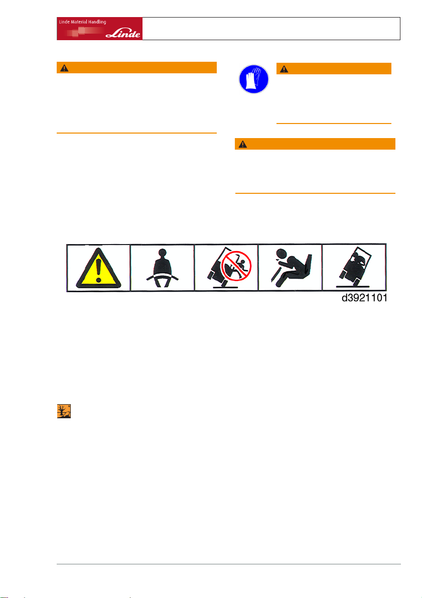
In the case of tip-over
• Stay buckled up
• Don’t jump
• Hold on tight
• Brace feet
•Leanaway
WARNING
Depending on the duration of
operation and use, components
carrying exhaust gases and exhaust
air can become hot.
Therefore wear protective clothing
WARNING
The fork lift truck working area must be adequately
lit.
If it is insufficiently lit, floodlights must be installed
to ensure that the driver can see properly
The stability of your truck is ensured if used
properly and as intended. Should the truck
tip over during an unapproved application or
due to incorrect operation, always follow the
instructions depicted below.
Handling fluids and lubricants
ENVIRONMENT NOTE
Always handle fluids and lubricants as required and as specified by the manufacturer.
• Only store fluids and lubricants in approved
containers at specified storage places.
• As they could be inflammable, do not allow
contact with hot objects or a naked flame.
• Only use clean containers when replenishing fluids and lubricants.
• Follow the manufacturer’s safety and
disposal instructions.
Operating Instructions – 393 807 1001 EN – 06/2006 9
• Do not spill fluids.
• Remove any spillage immediately with a
suitable binding agent and dispose of as
specified.
• Also dispose of used or contaminated fuels
and lubricants as specified.
• Follow laws and regulations.
• Clean the area surrounding the part in
question before lubrication, filter renewal
or repairs in the hydraulic system.
• Discard replaced parts in a way friendly to
the environment.
Page 20

2 Safety
Regulations
WARNING
Do not allow hydraulic oil under pressure, for
example at a leak, to penetrate the skin. Medical
aidisrequiredifsuchaninjuryoccurs.
Wear protective gear.
WARNING
Improper handling of coolants and coolant additives
puts your health and the environment at risk.
Observe manufacturer´s directions.
Experts
Experts are persons with a special training and
experience in servicing and testing industrial
trucks and familiar with the applicable worker’s
protection rules, safety regulations, directives
and generally recognised rules of the art
(DIN and VDE standards, technical rules of
members of the EU or EEA agreements) so
that they can give a qualified assessment
of the safe operating condition of industrial
trucks.
Operation of industrial trucks in plant area
Many plant areas are so-called limited public
traffic areas. In this sense, we would like to
advise you to check your company liability
insurance coverage, to ensure that possible
claims for damages caused by your truck
in limited public traffic areas in relation to
third parties are included in the insurance
coverage.
Regulations
Safety inspection
The accident prevention rules in some countries require that the fork lift truck must be
checked periodically for proper operation by
trained personnel. Please contact your authorised dealer for this inspection.
Diesel engine emissions
In Germany, fork trucks equipped with diesel
engines must conform to TRGS 554. According to this regulation, diesel engine emissions are hazardous materials causing cancer. They should not get into the air at the
workplace, if possible. If trucks equipped with
diesel engines are used in totally or partially
enclosed spaces, the labour protection authority must first be notified. Appropriate notices must be posted in the work areas (refer
to TRGS 554 for an example).
Soot filter inspection
The responsible authorities specify that soot
filters must be inspected and serviced every
six months by an expert. The results of the
inspection must be recorded in a "Diesel
Engine Emissions Inspection Certificate" and
attached to the log book (eg truck’s safety
inspection logbook).
10 Operating Instructions – 393 807 1001 EN – 06/2006
Page 21

Safety 2
Determination and assessment of hazards from use of industrial trucks
Determination and assessment of hazards from use of industrial
trucks
Check note
Hazard Action
Industrial truck
equipment does not
comply with local
provisions
Lack of skills and
qualification of driver
Lack of skills and
qualification of driver
Usage by unauthorised
persons
Industrial truck not in a
safe condition
Impaired visibility
through load
Contamination of
respiratory air
Contamination of
respiratory air
Impermissible usage
(improper usage)
Impermissible usage
(improper usage)
Impermissible usage
(improper usage)
When filling up with a)
diesel
When filling up with b)
fuel gas
When charging traction
batteries
Check
Driver training (sit-on
and stand-on industrial
trucks)
Instruction for pedestriancontrolled trucks
Access with key only for
appointed staff
Recurrent testing and
rectification of defects
Deployment planning
Assessment of diesel
exhaust gases
Assessment of fuel gas
exhaust gases
Issue of operating
instructions
Written notice of
instruction to driver
UVV-BGV D 27, observe
operating manual and
VDMA leaflet
UVV-BGV D 27, observe
operating manual and
VDMA leaflet
UVV-BGV D 27, observe
operating manual and
VDMA leaflet
UVV-BGV D 27, observe
operating manual, VDMA
leaflet and VDE 0510
X = actioned
- = not
concerned
Notes
If in doubt, consult
competent factory
inspectorate or
employers’ liability
insurance association
UVV-BGV D 27 - § 7,
BGG 925 driver permit
VDI 3313
UVV-BGV D 27 - §§ 9,
37, BGG 918
UVV-BGV D 27 - § 12
TRGS 554
MAK list (maximum workplace concentrations list)
UVV-BGV D 27 - § 5
UVV-BGV D 27 - §7
VDE 0510: In particular
a) ventilation b) insulation
value
Operating Instructions – 393 807 1001 EN – 06/2006 11
Page 22

2 Safety
Instructions for fitting attachments
In the Federal Republic of Germany the German Law on Health and Safety at Work (ArbSchG) states that it is up to the Employer to
assess which hazards are associated with
the work of employees and which Health and
Safety measures are required (§ 5 ArbSchG).
The result must be documented (§ 6 ArbSchG). In the case of industrial truck deployments involving similar hazard situations it is
permitted to summarise the results . In countries outside the Federal Republic of Germany
the country-specific regulations must be observed. With the list we are helping you to
comply with these regulations. The construction and equipment of industrial trucks comply
with the Machinery Directive 98/37/EC and
are identified by the CE mark accordingly.
This means that they do not fall under the
scope involved in the assessment of hazards,
and nor do attachments due to their own CE
marking . The operator must however select
the type and equipment of industrial trucks so
as to comply with the local provisions for deployment.
Instructions for fitting attachments
To depressurise the oil in the pipes beforefitting an additional hydraulic attachment
to the hydraulic system, a pressure receiver
(special equipment) can be used.
In order to ensure the safe usage of industrial
trucks we not only supply every industrial
truck with a copy of the operating manual but
also with the leaflet of the VDMA (German
Engineering Federation) specifying the rules
for the proper usage of industrial trucks "Rules
for the Proper Use of Industrial Trucks".
The list specifies key hazards which are most
frequently the cause of accidents in the event
of non-compliance. If other major hazards are
involved at a specific plant , they must be listed
additionally.
In many plants the conditions o
industrial trucks are by and la
that the hazards can be summar
list. The pronouncements of t
liability insurance associa
each case as regards this topi
taken into account.
For this consult the section "Operate attachments".
f use for
rge similar so
ised in one
he employers’
tion competent in
c should also be
12 Operating Instructions – 393 807 1001 EN – 06/2006
Page 23

3
Overview
Page 24
3 Overview
Rating plates
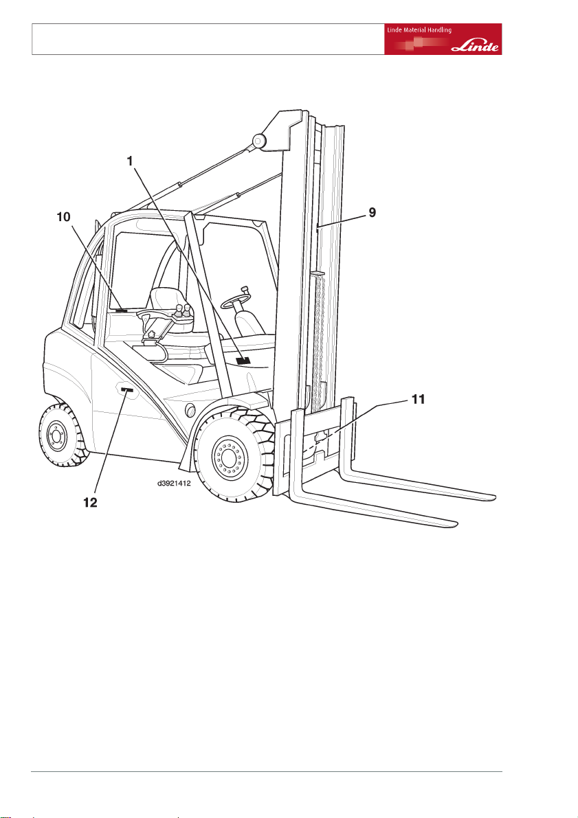
Rating plates
1 Nameplate
9 Lift mast number (stick-on label)
10 Chassis number (stamped into the rear wall
of the driver’s protective roof)
11 Rating plate for drive axle
12 Rating plate for engine
14 Operating Instructions – 393 807 1001 EN – 06/2006
Page 25
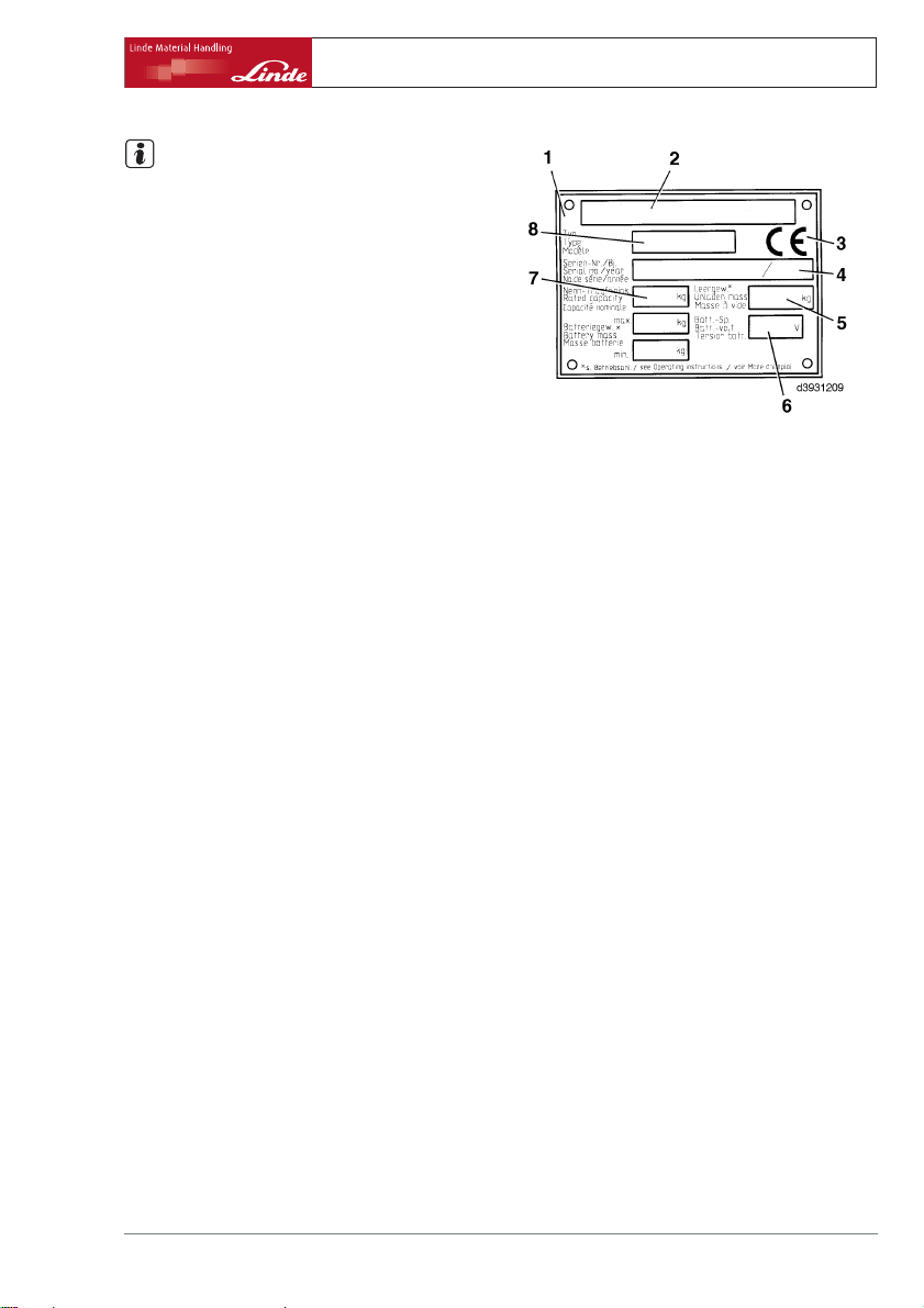
NOTE
The CE mark confirms compliance with the EC
machinery directive and with all regulations
applicable to fork lift trucks .
Overview 3
Rating plates
1 Nameplate
2 Manufacturer
3CEmark
4 Serial No. / build year)
5 Tare weight
6 Battery voltage
7 Nominal load capacity
8 Type
Operating Instructions – 393 807 1001 EN – 06/2006 15
Page 26
3 Overview
General view
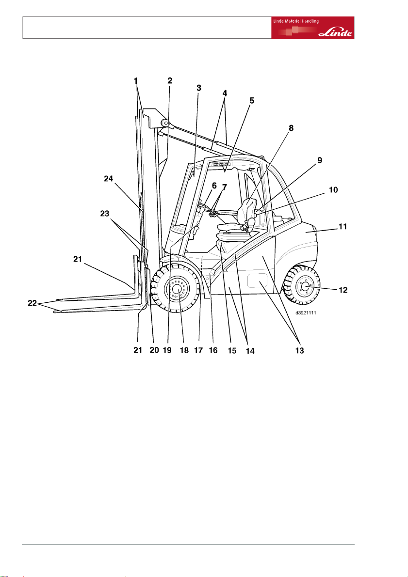
General view
1Mast
2 Lift cylinder
3 Composite instrument
4 Tilt cylinders
5 Toggle switch for auxiliary functions (op-
tional)
6 Steering wheel/hydrostatic power steering
7 Control lever (joystick)
8 Operator’s seat
9 Electrical system cover
10 Fuses (behind the electrical system cover)
11 Counterweight
12 Steering axle
16 Operating Instructions – 393 807 1001 EN – 06/2006
13 Maintenance access covers
14 Chassis and overhead guard
15 Engine bonnet
16 Step for mounting and dismounting
17 Fuses (in the engine compartment)
18 Wheel motor, left
19 Handwheel for adjusting steering column
20 Fork carriage
21 Fuses, forks
22 Forks
23 Forks, locking
24 Lift chain (only for duplex or triplex mast)
Page 27

Controls
4
3
2
1
Overview 3
Controls
56 879
10
11
18
12
d3921508
14151617
1 Parking brake handle
2 Handwheel for adjusting steering column
3 Combined lever for wiper/washer and
blinker (option)
4 Steering wheel/hydrostatic power steering
5 Signal button
6 Ignition switch with ignition key
7 Cubby hole
8 Control lever (joystick) for working hy-
draulics
9 Control lever (joystick) for auxiliary hy-
draulics (attachments) (option)
Operating Instructions – 393 807 1001 EN – 06/2006 17
10 Symbol label for auxiliary hydraulics (attach-
11 Symbol label for working hydraulics
12 Operator’s seat armrest
13 Operator’s seat
14 Forward accelerator
15 Brake pedal
16 Reverse accelerator
17 Backrest cushion adjuster (option)
18 Plate "Guaranteed acoustic power level"
13
ments) (option)
Page 28
3 Overview
Indicator unit
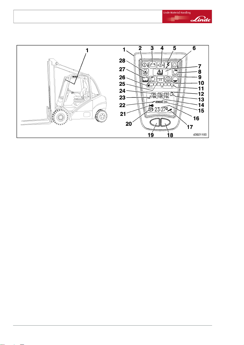
Indicator unit
1 Indicator unit
2 Hydraulic oil temperature indicator
3 Battery charge indicator
4 Engine oil pressure indicator / Engine oil
level indicator (special equipment)
5 Electrical control system fault
6 Engine temperature indicator
7 Load / overload indicator (special equip-
ment)
8 not assigned
9 Level display (special equipment)
10 Hydraulic oil micro-filter indicator (special
equipment)
11 Fuel tank level display
12 Display
13 not assigned
14 Display operating hours
(2) Hydraulic oil temperature indicator (colour
red)
Lights up when the specified temperature
limit is reached. A buzzer sounds when the
permissible temperature limit is reached.
• Insufficient oil in the hydraulic system
• Incorrect oil used
• Oil filter clogged
• Oil cooler clogged
• Switch buzzer off with the reset button (19).
(3) Battery charge indicator (colour red)
15 Symbol operating hours
16 Display time
17 Symbol service interval exceeded
18 Function push-button
19 Reset button
20 Symbol parking brake applied
21 Symbol "do not start the engine"
22 Symbol operating hours (until next service
shown for only 4 sec on display field (14))
23 Symbol lift mast position sensing
24 Text field
25 Glow plug indicator
26 Air filter induction pressure indicator
27 Coolant water level display (special equip-
ment)
28 not assigned
Lights up when there is a fault in the battery
charger system.
• Ribbed vee belt broken or ribbed vee belt
tension too slack
• Ribbed vee belt tensioner defective
• Cable defective
• Alternator defective
• Charge controller or controller switch
defective.
(4) Engine oil pressure indicator / Engine oil
level indicator (special equipment) (colour
red)
18 Operating Instructions – 393 807 1001 EN – 06/2006
Page 29

Overview 3
Indicator unit
When engine lubricating oil pressure is
too low this indicator lights up, and also a
buzzer sounds. In addition the text field (24)
displays the text
downwards indicates that the engine oil level
is too low.
• Insufficient oil in the crankcase
• Engine too hot
• Incorrect oil used
• Internal leakage in the lubricating oil circuit
• Top up with engine oil
• Switch buzzer off with the reset button (19).
(5) Electrical control system fault (colour red)
Lights up when an electrical contro
fault is present, and displays a fau
text field (24).
(6) Engine temperature indicator (colour red)
Lights up when the specified temperature
limit is reached. A buzzer sounds when the
permissible temperature limit is reached.
• Fan motor defective
• Thermostatic switch defective
• Radiator clogged
• Leakage in the coolant circuit
• Coolant level too low
• Switch buzzer off with the reset button (19).
(7) Load / overload display (special equ
ment)
Symbol lights up orange when load is normal.
DANGER
Symbol lights up red when overloaded.
Set down load immediately.
• Consult load diagram.
(8) not assigned
(9) Level display (colour yellow) (special
equipment)
Lights up when the coolant level is below the
minimum.
• Top up the coolant.
Oil A double arrow pointing
l system
lt code in
ip-
Please contact your authorised dealer.
(10) Hydraulic oil micro-filter indicator (colour
yellow) (special equipment)
Lights up when the micro-filter r
maintenance.
• Micro-filter clogged, exchange it.
(11) Fuel tank level display (colour depending
on the level, green or red
• Shows the current fuel tank level.
(13) not assigned
(14) Display operating hours
Shows the operating hours of the fo
This indicator is an shows the fork
operating hours and indicates the
and maintenance work to be perform
NOTE
If a defective indicator unit is exc
the operating hours up to that poi
recorded. Note the data on an embo
attached near the indicator unit
the option of subsequently updat
indicator unit. Please contact y
equires
rklift truck.
lift truck’s
inspection
ed.
hanged,
nt must be
ssed strip
. There is also
ing the new
our authorised
dealer.
(15) Symbol operating hours
Flashes when operating hours are
counted (only when the ignition i
engine speed exceeds 500 rpm
(16) Display clock
24-hour clock display
Can be adjusted using buttons (18) a
Resetting to 12-hour clock display is possible
using a diagnostic tester. Please contact your
authorised dealer.
(17) Symbol service interval exceeded
If the number of operating hours unt
service is less than or equal to 0, th
flashes for 10 sec every time the veh
started, and then lights up contin
Adjustment and reset of the intervals can be
performed only using the diagnostic tester
being
sonandthe
)
nd (19.)
il the next
e symbol
icle is
uously.
Operating Instructions – 393 807 1001 EN – 06/2006 19
Page 30

3 Overview
Indicator unit
provided for this purpose. Please contact your
authorised dealer.
(18) Function push-button
Assignment depending on version
(19) Reset button (special equipment)
To adjust the time, switch off the warning
buzzer and other functions depending on the
version.
(20) Symbol parking brake
Lights up when the parking brake is applied.
(21) Symbol "do not start the engine"
Lights up when the engine has stall
NOTE
.
ed.
It is essential to leave the ignition switched on
until this symbol has gone out (depending on
the oil temperature this may be between 15
and 50 seconds). Then attempt to restart the
engine.
(22) Symbol operating hours until
After the ignition has been switched on,
display field (14) shows the operating hours
until the next service (counting backwards).
Symbol (22) lights up. After 5 seconds symbol
22 goes out and indicator (14) automatically
switches to the operating hours of the forklift
truck; the operating hours symbol (15) flashes.
next service
(23) Symbol lift mast position sensing (special
equipment)
Lights up when the function "lift mast position
sensing" is enabled .
(24) text field
Serves as a display field. Please contact your
authorised dealer for interpretation of fault
codes.
(25) Glow plug indicator (colour yellow)
Lights up whilst the glow plugs are
up, then goes out.
Flashes if there an engine fault or engine
management fault occurs. Please contact
your authorised dealer.
(26) Air filter induction pressure indicator
(colour yellow)
Lights up when the air filter is exc
clogged.
• Air filter clogged, exchange it.
(27) Coolant water level display (colour
yellow) (special equipment)
Lights up when the coolant level is b
minimum.
• Top up the coolant.
(28) not assigned
warming
essively
elow the
20 Operating Instructions – 393 807 1001 EN – 06/2006
Page 31

4
Operation
Page 32

4 Operation
Standard equipment
Running-in instructions
The lift truck can be operated at full speed
directly. Avoid sustained high loads on the
working hydraulic system and the travel
drive in the first 50 hours of operation. The
wheel fasteners must be tightened before the
commissioning and after each wheel change.
Checks before starting work
¾ Check the fuel level
¾ Check the engine oil level
¾ Check the hydraulic oil level
Standard equipment
Adjusting the driver’s seat
WARNING
An incorrect adjustment of the seat can cause back
injury. Do not operate the seat adjusting devices
while operating the truck.
Before each start-up of the truck and with each
change in driver, set the weight setting to the individual weight of the driver and check if all settings are
correctly engaged. Do not place any objects in the
vicinity of the controls.
Thereafter at least every 100 operating hours.
Tighten opposite wheel fasteners to a torque
of
front:
rear:
¾ Check the coolant level
¾ Check the tyre pressures
170 Nm
460 Nm
22 Operating Instructions – 393 807 1001 EN – 06/2006
Page 33

Horizontal adjustment
¾ Lift lever (2) up and pull it.
¾ Move the driver’s seat on the sli
backwards or forwards to give th
the best position in relation to
wheel and the accelerator pedal
¾ Re-engage the lever.
de rails
edriver
the steering
s.
Backrest adjustment
¾ Push up and hold the backrest adjuster (1).
¾ Move the backrest forward and bac
comfortable sitting position fo
found.
¾ Release the backrest adjuster (1).
k until a
r the driver is
Adjusting the lumbar support (option)
¾ Turn knob (3) until a comfortable sitting
position is achieved.
Turning the knob anticlockwise makes the
backrest arch outwards.
Turning the knob clockwise returns the backrest to its original position.
d3921352
Operation 4
Standard equipment
1
2
3
6
Adjusting for the operator’s weight
¾ Turn the adjusting handwheel (5) to set the
cushioning to the weight of the driver.
The adjustment range from 50 kg to 130 kg is
visible at the weight range indicator (4).
To reduce the weight, turn the handwheel
anticlockwise.
To increase the weight, turn the handwheel
clockwise.
Operating Instructions – 393 807 1001 EN – 06/2006 23
5
4
d3921353
Page 34

4 Operation
Standard equipment
Adjusting the seat angle of tilt (option)
¾ Lift the handle (6).
The seat is tilted to the desired
applying or taking off one’s wei
ously.
Adjusting the seat position (
¾ Lift the handle (9).
The desired position is reached by simultaneously sliding the seat forward or back.
Adjusting the backrest extension (option)
¾ Push the backrest extension (7
for an individual adjustment.
Turning the seat heating on/off
¾ Toggle the switch (8) on or off.
NOTE
Long sitting puts excessive strain on the spinal
column. Prevent strain with regular, light exercising.
position by
ght simultane-
option)
)upordown
(option)
7
9
8
d3921354
Adjusting the armrest on the operator’s
seat
NOTE
The armrest on the operator’s s
automatically by spring press
eat is raised
ure after the
handwheel (1) is loosened.
24 Operating Instructions – 393 807 1001 EN – 06/2006
Page 35

Operation 4
Standard equipment
¾ Sit down on the operator’s seat and loosen
the handwheel (1).
¾ Push the armrest (3) down against the force
of the spring until a comfortable position for
the arm is reached.
¾ Tighten the handwheel (1).
¾ Loosen the handwheel (2) and slide the
armrest (3) back and forth until the control
lever (4) is easily accessible.
¾ Tighten the handwheel (2).
Adjust the steering column
DANGER
If the clamping screw is loose, safe driving is not
possible.
The steering column may only be adjusted when
the truck is stationary.
Tilt adjustment
¾ Loosen the clamping screw (2) in counter-
clockwise direction.
¾ Move the steering wheel (1) to the desired
position.
¾ Tighten the clamping screw (2) in clockwise
direction.
4
3
2
1
d3921416
1
Height adjustment (Optional)
¾ Loosen the clamping screw (2) counter-
clockwise.
¾ Pull the steering wheel (1) upwards, or push
it downwards, to the desired position.
¾ Tighten the clamping screw (2) clockwise.
Operating Instructions – 393 807 1001 EN – 06/2006 25
2
t3921369
Page 36

4 Operation
Standard equipment
Setting the clock
NOTE
The time is shown in the 24 hour mode.
Change to 12 hour mode with diagnostic unit.
Please contact your authorised dealer for this
service.
¾ Depress both buttons (2) and (3) simultane-
ously for 3 seconds.
The hour readout in the time dis
NOTE
The setting of the hours or minutes can be
adjusted slowly with button (2) by tipping it or
fast by holding it.
¾ Depress button (2) to set the h
¾ Depress button (3) to confirm the hour set-
ting.
Now the minute readout blinks.
¾ Depress button (2) to set the mi
¾ Depress button (3) to confirm the setting of
the minutes.
play (1)blinks.
ours.
nutes
1
3
2
d3921348
Lap seat belt
Applying the lap seat belt
DANGER
It is dangerous to leave the truck in
an uncontrolled manner.
Therefore always keep buckled up
when operating the truck! Only one
person may be fastened with the
seat belt.
WARNING
The proper operation of the lap belt must be guaranteed.
Therefore do not let the belt get twisted, caught
or tangled. Protect the lock and retractor against
foreign objects, damage and dirt.
26 Operating Instructions – 393 807 1001 EN – 06/2006
Page 37

NOTE
Cabins with closed solid doors or guards comply with the safety requirements for driver
restraint systems. The lap seat belt can be applied optionally. However, it must be applied
when driving with the doors open or removed.
PVC doors are not considered to be an operator restraint system.
The automatic blocking system locks the belt
when the truck tilts heavily. The belt can then
no longer be pulled out of the retractor. To
loosen the automatic blocking system of the
truck, drive off the slope carefully.
During the operation of the truck (eg driving,
operation of the mast, etc), sit as far back as
possible so that the back contacts the backrest. The retractor’s automatic blocking system sufficient freedom of movement during
normal truck operation.
¾ Pull the lap seat belt (1) gent
retractor on the left.
¾ Place the belt over the thighs, not over the
abdomen.
¾ Engage the tongue (2) in belt lock (4).
¾ Check seat belt tension.
The belt should be snug on the body.
ly from the
Operation 4
Standard equipment
5
1
4
Opening the lap seat belt
¾ Press the red button (5) on the lock (4).
¾ Return the tongue (2) to the retr
with the hand.
NOTE
actor (3)
2
3
d3921415
If the belt is retracted too fast the automatic
blocking system can be triggered when the
tongue hits the case. The belt can not be
pulled out with the usual force.
Operating Instructions – 393 807 1001 EN – 06/2006 27
Page 38

4 Operation
Standard equipment
Drive motor (two-pedal operation)
Starting motor
DANGER
Risk of poisoning!
Do not allow motor to run in unventilated rooms.
NOTE
Where possible, avoid starting up the motor
frequently and short service periods to ensure that the combustion engine attains its
operating temperature. Frequent cold-starts
encourage wear.
¾ The joystick must be in neutral.
¾ Sit down on the driver’s seat.
¾ Fasten the seat belt.
¾ Place both feet on the accelerator pedals
(4).
¾ Parking brake handle (1) engaged, (motor
will only start when parking brake handle is
engaged).
¾ Insert switch key (2) into the ignition and
starting switch and turn from the zero position to position "I" .
The electrical system is switched on.
1
2
3
d3921417
28 Operating Instructions – 393 807 1001 EN – 06/2006
4
4
Page 39

Operation 4
Standard equipment
¾ Check the indicator unit (3).
NOTE
After switching on the ignition the indicator unit
will perform a self-test . The displays all light
up for approx. 2 seconds and the operating
hours until the next service are displayed for
5 seconds in the indicator unit (3) display field
(11). During this time symbol (12) remains
lit. After 5 seconds the display reverts automatically to the operating hours. If the buzzer
sounds (particulate filter unit fault), check the
lamps (see Diesel motor faults, cause, remedies). If the buzzer continues to sound, please
contact your local authorised dealer.
The following controls light up:
• Symbol (9) parking brake engaged,
• Motor oil pressure indicator (
• Battery charge indicator (5),
• Glow plug indicator (13).
¾ Wait until the glow plug indicat
out
¾ Turn switch key to position "II".
As soon as the motor starts
¾ release the switch key.
Symbol (7) will flash on and off.
CAUTION
For vehicles with particulate filter units only. If the
exhaust is very smoky and remains so, switch off.
Please contact your authorised dealer.
Every time the engine is started, watch the exhaust
pipe outlet for about 5 seconds.
6),
or (13) goes
13
12
11
10
3
56
7
9
8
d3921349
If motor fails to start
¾ After the glow plugs have heated up, keep
turning the starter motor until the motor runs
at idling speed . Depending on the vehicle,
the temperature and the altitude, this can
take more than 1 minute.
If the motor stalls, the symbol" Do not start the
motor"(10) will appear.
Operating Instructions – 393 807 1001 EN – 06/2006 29
Page 40

4 Operation
Standard equipment
¾ Always leave ignition switched on until sym-
bol extinguishes (between 15 und 50 seconds depending on oil temperature).
¾ Then try to restart.
When trying to start the motor, wa
for min. 1 minute to protect the ba
motor still does not start at th
consult: Malfunctions, Cause
The Charging and Motor oil pressure symbols
must extinguish once the motor starts to run
smoothly.
Motor speed is regulated automatically depending on the load on the motor.
NOTE
Do not allow motor to warm up at id
Under load drive truck at a brisk
motor will warm up quickly.
Switchingoffthemotor
CAUTION
For motors with a turbocharger, the high speed of
the turbocharger shaft (approx. 100 000 rpm at
full load) could cause the shaft bearing to run dry
through lack of lubrication thus damaging it.
Do not switch off motor under full load, but rather
allow to run on for a few minutes at low speed.
it each time
ttery. If the
e third attempt,
s and Remedy.
ling speed.
speed . The
¾ Take your feet off the accelerator pedals
(3).
¾ Move switch key (2) into zero position.
NOTE
1
2
The brake becomes active when the motor is
switched off.
¾ Pull up parking brake handle (1).
¾ Remove the switch key (2) when leaving the
truck.
d3921418
30 Operating Instructions – 393 807 1001 EN – 06/2006
3
3
Page 41

Driving (double-pedal operation)
WARNING
Driving on gradients over 15 % is generally not
allowed due to the specified minimum brake applications and the stability values. Contact your
authorised dealer before driving on steeper gradients. The climbing ability values given in the data
sheet have been derived from the drawbar pull and
apply only for crossing obstacles and short differences in height.
Always adapt your driving style to the conditions
of the roadway (rough surfaces, etc.), especially
hazardous work zones and the load.
WARNING
If mirrors are used, please note the rear-view mirror
is only provided for observing the traffic area to the
rear.
If you are reversing, therefore, always look over the
shoulder in the direction your are reversing.
CAUTION
Possibly fitted side doors must be protected against
damage.
Therefore always ensure both side doors are closed
and locked before driving.
Operation 4
Standard equipment
NOTE
The truck can only be driven with the operator
seated.
¾ Start the engine.
¾ Raise the forks slightly and tilt the mast
back.
Operating Instructions – 393 807 1001 EN – 06/2006 31
Page 42

4 Operation
Standard equipment
¾ Push the parking brake handle (1) down.
Forward travel
¾ Depress the right accelerator (2) gently.
Truck speed depends on how far the
depressed.
NOTE
Flooring the accelerator does n
speed as maximum acceleration i
pedal is
ot increase the
s controlled
automatically.
Reversing
¾ Depress the left accelerator (4) gently.
The truck willreverse slowly or fast, depending
on how far the accelerator is depressed.
Changing the direction of travel
¾ Release the depressed accelerat
The hydrostatic drive will act as service brake.
¾ Depress the accelerator for the opposite
direction of travel.
The truck will now accelerate in th
direction.
¾ Keep both feet on the accelerators to main-
tain easy control over all truck movements.
The accelerators can be operated directly.
The hydrostatic drive will brake the truck to a
full stop and then accelerate it in the opposite
direction of travel.
or.
e selected
d3921419
1
4
3
2
32 Operating Instructions – 393 807 1001 EN – 06/2006
Page 43

Starting on gradients
¾ Fully depress the brake pedal (3).
¾ Push the parking brake handle (1
¾ Release the brake pedal half way.
¾ Depress accelerator (2) or (4).
¾ Slowly release the brake pedal fu
The brake is released and the truck will drive
without rolling back.
) down.
lly.
Stopping
¾ Release the depressed accelerator slowly.
The hydrostatic drive will act as s
¾ When stopping on gradients, keep both feet
on the accelerators and compensate drive
slippage by lightly depressing the accelerator in the "upslope" direction of travel.
¾ Depress the brake pedal (3) for a long stop.
¾ When dismounting form the truck w
engine running, for example, to b
form some actions in close vicini
truck (opening a gate, unhitchin
etc.), always pull the parking br
(1) and release the seat belt. In c
longer stop, shut down the engine
the parking brake handle (1).
¾ Remove the ignition key when leaving the
truck unattended.
ervice brake.
ith the
riefly per-
ty of the
gatrailer,
ake handle
ase of a
and pull
d3921419
Operation 4
Standard equipment
1
4
3
2
1
Drive motor (single-p
edal operation)
d3921419
4
3
2
Starting motor
DANGER
Risk of poisoning!
Do not allow motor to run in unventilated rooms.
Operating Instructions – 393 807 1001 EN – 06/2006 33
Page 44

4 Operation
Standard equipment
NOTE
Where possible, avoid starting up the motor
frequently and short service periods to ensure that the combustion engine attains its
operating temperature. Frequent cold-starts
encourage wear.
¾ Sit down on the driver’s seat.
¾ Fasten the seat belt.
¾ Move the operating lever (hydra
direction of travel (5) into neu
ulics and
tral.
5
d3921361
¾ Place foot on accelerator pedal (4).
¾ Parking brake handle (1) engaged, (motor
will only start with parking brake handle
engaged).
¾ Insert switch key (2) into the ignition and
starting switch and turn from the zero position to position "I".
The electrical system is switched on.
34 Operating Instructions – 393 807 1001 EN – 06/2006
1
d3921420
2
3
4
Page 45

Operation 4
Standard equipment
¾ Check the indicator unit (3).
NOTE
After switching on the ignition the indicator unit
will perform a self-test. The displays all light up
for approx. 2 seconds and the operating hours
until the next service are displayed for 5 seconds in the indicator unit (3) display field (12).
During this time symbol (13) remains lit. After
5 seconds the display reverts automatically
to the operating hours. If the buzzer sounds
(particulate filter unit fault), check the lamps
(see Diesel motor faults, cause, remedy). If
the buzzer continues to sound, please contact
your local authorised dealer.
The following controls light up:
• Symbol (10) Parking brake engaged
• Motor oil pressure indicator (
• Battery charge indicator (6),
• Glow plug indicator (14).
¾ Wait until the glow plug indicat
out
¾ Turn switch key to position "II".
As soon as motor starts,
¾ release switch key.
Symbol (8) flashes on and off.
CAUTION
Only for vehicles with particulate filter units. If the
exhaust is very smoky and remains so, switch off
the motor. Please contact your authorised dealer.
Every time the engine is started, watch the exhaust
pipe outlet for about 5 seconds.
7),
or (14) goes
14
13
12
11
3
67
8
10
9
d3921359
If motor fails to start
After the glow plugs have heated up, keep
turning the starter motor until the motor runs
at idling speed. Depending on the vehicle,
the temperature and the altitude, this can take
more than 1 minute.
If the motor stalls, the symbol " Do not start
motor"(11) will appear.
Operating Instructions – 393 807 1001 EN – 06/2006 35
Page 46

4 Operation
Standard equipment
¾ Always leave ignition switched on until sym-
bol extinguishes (between 15 und 50 seconds depending on oil temperature).
¾ Then try to restart.
When trying to start the motor, wa
for min. 1 minute to protect the ba
motor still does not start at th
consult: Malfunctions, Cause
The Charging and Motor oil pressure symbols
must extinguish once the motor runs smoothly.
Motor speed is regulated automatically depending on the load on the motor.
NOTE
Do not allow motor to warm up at id
Drive truck, under load, at a bri
motor will reach operating stat
quickly.
Switching off motor
CAUTION
For motors with a turbocharger, the high speed of
the turbocharger shaft (approx. 100 000 rpm at
full load) could cause the shaft bearing to run dry
through lack of lubrication thus damaging it.
Do not switch off motor under full load, but rather
allow to run on for a few minutes at low speed.
it each time
ttery. If the
e third attempt,
s and Remedy.
ling speed.
sk speed. The
e temperature
¾ Take foot off accelerator pedal (3).
36 Operating Instructions – 393 807 1001 EN – 06/2006
1
d3921421
2
3
Page 47

¾ Move direction of travel lever (4) into neu-
tral.
¾ Move switch key (2) into zero position.
NOTE
The brake becomes active when the
motor is
switched off.
¾ Pull up parking brake handle (1).
¾ Remove the switch key (2) when le
aving the
truck.
Driving (single-pedal operation)
WARNING
Driving on long gradients over 15 % is generally
not allowed due to the specified minimum brake
applications and the stability values. Contact your
authorised dealer before driving on steeper gradients. The climbing ability values given in the data
sheet have been derived from the drawbar pull and
apply only for crossing obstacles and short differences in height.
Always adapt your driving style to the conditions
of the roadway (rough surfaces, etc.), especially
hazardous work zones and the load.
Operation 4
Standard equipment
4
d3921362
WARNING
If mirrors are used, please note the rear-view mirror
is only provided for observing the traffic area to the
rear.
If you are reversing, therefore, always look over the
shoulder in the direction your are reversing.
CAUTION
Possibly fitted side doors must be protected against
damage.
Therefore always ensure both side doors are closed
and locked before driving.
Operating Instructions – 393 807 1001 EN – 06/2006 37
Page 48

4 Operation
Standard equipment
NOTE
The truck can only be driven with the operator
seated.
¾ Start the engine.
¾ Raise the forks slightly and tilt the mast
back.
¾ Push the parking brake handle (
Forward travel
¾ Push the direction lever (4) forward.
¾ Depress the accelerator (3) gently.
Truck speed depends on how far th
depressed.
NOTE
Flooring the accelerator does no
speed as maximum acceleration is
automatically.
1) down.
e pedal is
t increase the
controlled
1
Reversing
¾ Pull the direction lever (4) back.
¾ Depress the accelerator (3) gently.
The truck willreverse slowly or fa
on how far the accelerator is depre
Changing the direction of trave
¾ Release the accelerator.
The hydrostatic drive will act as service brake.
38 Operating Instructions – 393 807 1001 EN – 06/2006
st, depending
ssed.
l
d3921422
2
3
Page 49

¾ Move the direction lever (4) to the opposite
direction of travel.
The truck will now accelerate in the selected
direction.
The direction lever can be moved d
the opposite direction. The hydr
will brake the truck to a full st
celerate it in the opposite dir
irectly to
ostatic drive
op and then ac-
ection of travel.
Starting on gradients
¾ Fully depress the brake pedal (2).
¾ Push the parking brake handle (1) down.
¾ Release the brake pedal half way.
¾ Depress the accelerator (3).
¾ Slowly release the brake pedal fully.
The brake is released and the truck will drive
without rolling back.
Operation 4
Standard equipment
4
d3921362
1
Stopping
¾ Release the accelerator slowly.
The hydrostatic drive will act as service brake.
3
¾ When stopping on gradients, keep the foot
on the accelerator, move the direction lever
(4) to the "upslope" direction of travel and
compensate drive slippage by depressing
the accelerator slightly.
¾ Depress the brake pedal (2) for a long stop.
¾ When dismounting form the truck with the
engine running, for example, to briefly perform some actions in close vicinity of the
truck (opening a gate, unhitching a trailer,
etc.), always pull the parking brake handle
(1) and release the seat belt. In case of a
longer stop, shut down the engine and pull
the parking brake handle (1).
Operating Instructions – 393 807 1001 EN – 06/2006 39
d3921422
2
Page 50

4 Operation
Standard equipment
¾ Remove the ignition key when leaving the
truck unattended.
Steering system
Steering
The hydrostatic steering system means that
the level of effort required to turn the steering
wheel is very low. This is particularly advantageous when palletising in narrow aisles.
¾ Starting and driving.
¾ Turn the steering wheel to the left and right
as far as it will go.
Apply sufficient force to move the steering
wheel beyond the limit stop making sure that
the position of the wheels on the steering axle
does not change.
DANGER
The forklift truck must not be driven if the steering
system is defective.
If the steering is stiff or has too much play, contact
your local authorised dealer.
d3921423
Turning radius
H25 2420mm
H30 2444mm
H35 2476mm
40 Operating Instructions – 393 807 1001 EN – 06/2006
Page 51

Braking system
Service brake
¾ Allow accelerator pedals (1) to move to the
neutral position.
The hydrostatic drive acts as th
brake. Slow or quick release of
erator pedals to the neutral po
the braking action to be sensit
from gentle to hard braking.
NOTE
For emergency braking, apply the STOP pedal
(2) located between the accelerator pedals.
This causes a full brake application.
eservice
the accel-
sition allows
ively controlled,
Operation 4
Standard equipment
Stop pedal
NOTE
The stop pedal (2) is not a sensitive service
brake but a sharply applied parking brake. Its
use whilst driving should be avoided, because
this can cause the drive wheels to lock and
in certain circumstances can cause the load
to slip from the fork arms. In unfavourable
situations the engine can also stall. A wait of
about 30 seconds must then elapse to allow
the variable pump in the traction drive to return to a neutral setting . It is recommended
that drivers familiarise themselves with the
function and action of this brake without any
load on the forklift truck. For this purpose they
should choose a route without any other traffic, and drive at low speed.
Parking brake
Themulti-discbrakesare
brake of the fork-lift tru
used as the parking
ck.
d3921424
1
2
1
Operating Instructions – 393 807 1001 EN – 06/2006 41
Page 52

4 Operation
Standard equipment
Apply the parking brake
¾ Pull the parking brake handle (3) upwards.
The symbol on the indicator unit
Release the parking brake
NOTE
The multi-disc brake will release only if the
engine is running.
¾ Release parking brake handle (3) down-
wards.
The symbol on the indicator unit will go out.
DANGER
The forklift truck must not be driven if the braking
system is defective.
Should there be any defects or wear apparent in
the braking system, please contact your authorised
dealer at once.
Horn
Operating the horn
When operating at blind corners and junctions,
a horn serves as warning signal.
¾ Press the horn button ((1)) on the steering
wheel to sound the horn.
will light up.
3
d3921425
42 Operating Instructions – 393 807 1001 EN – 06/2006
Page 53

Lifting system and attachments (central lever operation)
WARNING
With the moving lift mast or any
attachment there is a risk of the driver
getting caught in between.
Therefore never reach or step into
the lift mast or the space between
the lift mast and the vehicle. The
lifting system and attachments
should only ever be used for their
proper purpose. Drivers must be
instructed in the handling of the lifting
system and attachments. Bear the
maximum lift height in mind.
NOTE
When working with a bucket, see "forklift truck
operation using a bucket".
NOTE
With the central lever version, use of the operating lever in an intermediate position (approx.
45°) will activate both functions at the same
time (e.g. lifting and tilting).
¾ Take note of the switching symbols with
arrows.
The operating lever should always be operated carefully, never jerkily. Moving the
operating lever determines the lifting, lowering and tilt speed . After the operating lever is
released, it automatically returns to its initial
position.
Operation 4
Standard equipment
NOTE
The lifting system and attachments only function with the motor running and the driver’s
seat under load.
d3931329
Operating Instructions – 393 807 1001 EN – 06/2006 43
Page 54

4 Operation
Standard equipment
Tilt lift mast forwards
¾ Move operating lever (1) forwards.
Tilt lift mast backwards
¾ Pull back operating lever (1) .
Lift fork carriage
DANGER
When lifting the lift mast there is an increased risk
of falling and crushing.
For this reason it is not permitted to step onto the
fork arms when lifted without a protective cage .
¾ Move operating lever (1) to the right.
Lower fork carriage
¾ Move operating lever (1) to the left.
Operate attachments
Attachments can be fitted to the truck as special equipment (e.g. sideshift, clamps etc.).
Take note of the operating pressure and operating manual for the attachment. Another
operating lever is attached for operation.
d3921370
1
2
NOTE
Before fitting an attachment, the depressurisation circuit (special equipment) can be used
to depressurise the hydraulic system for the
additional hydraulics so that the union nuts on
the fork carriage can be opened.
¾ Switch off the engine.
¾ Switch on the ignition.
¾ Operate the lever for the respective addi-
tional hydraulics several times.
¾ Unscrew the union nuts on the fork carriage.
¾ Screw on hoses for attachment or connect
plug-in couplings.
44 Operating Instructions – 393 807 1001 EN – 06/2006
Page 55

CAUTION
Attachments affect the load capacity and stability of
the forklift truck.
Attachments which are not supplied with the forklift
truck should only be used when the authorised dealer has checked that safe operation is ensured by
the allocation in terms of load capacity and stability .
¾ Take note of the switching symbols with
arrows.
NOTE
For every attachment device, a plate stating
the load capacity of the truck must be affixed
beside the load diagram in the top left of the
driver’s protective roof, and a symbol label
for the relevant attachment must be affixed
behind the operating lever.
Operate sideshift
NOTE
In order to prevent damage, do not activate the
sideshift when the fork arm is on the ground.
¾ Move operating lever (2) to the left.
Sideshift moves to the left.
¾ Move operating lever (2) to the right.
Sideshift moves to the right.
Operation 4
Standard equipment
1
2
d3931328
Activate the clamp
¾ Move operating lever (2) forwards.
Clamp opens.
¾ Pull back operating lever (2).
Clamp closes.
Activate the fork arm adjustment device
NOTE
d3921370
In order to prevent damage, do not activate
the fork arm adjustment device with a load or
the fork arm on the ground. Do not use the fork
arm adjustment device as a clamp.
Operating Instructions – 393 807 1001 EN – 06/2006 45
Page 56

4 Operation
Standard equipment
¾ Move operating lever (2) forwards.
Fork arms move outwards.
¾ Pull back operating lever (2).
Fork arms move inwards.
Lifting system and attachments (single lever operation)
WARNING
With the moving lift mast or any
attachment there is a risk of the driver
getting caught in between.
Therefore never reach or step into
the lift mast or the space between
the lift mast and the vehicle. The
lifting system and attachments
should only ever be used for their
proper purpose. Drivers must be
instructed in the handling of the lifting
system and attachments. Bear the
maximum lift height in mind..
NOTE
When working with a bucket, see "forklift truck
operation using a bucket".
46 Operating Instructions – 393 807 1001 EN – 06/2006
Page 57

¾ Take note of the switching symbols with
arrows.
The operating lever should always be operated carefully, never jerkily. Moving the
operating lever determines the lifting, lowering and tilt speed . After the operating lever is
released, it automatically returns to its initial
position.
NOTE
The lifting system and attachments only function with the motor running and the driver’s
seat under load.
Lift fork carriage
DANGER
When lifting the lift mast there is an increased risk
of falling and crushing.
For this reason it is not permitted to step onto the
fork arms when lifted without a protective cage .
¾ Pull back operating lever (1) .
Lower fork carriage
¾ Move operating lever (1) forwards.
Operation 4
Standard equipment
Tilt lift mast forwards
¾ Move operating lever (2) forwards.
Tilt lift mast backwards
¾ Pull back operating lever (2).
Operate attachments
Attachments can be fitted to the truck as special equipment (e.g. sideshift, clamps etc.).
Take note of the operating pressure and operating manual for the attachment. One or more
additional operating levers are fitted for operating the attachments.
NOTE
Before fitting an attachment, the depressurisation circuit (special equipment) can be used
to depressurise the hydraulic system for the
Operating Instructions – 393 807 1001 EN – 06/2006 47
Page 58

4 Operation
Standard equipment
additional hydraulics,so that the union nuts on
the fork carriage can be opened.
¾ Switch off the engine.
¾ Switch on the ignition.
¾ Operate the lever for the respective addi-
tional hydraulics several times.
¾ Unscrew the union nuts on the fork
¾ Screw on hoses for attachment or connect
plug-in couplings.
CAUTION
Attachments affect the load capacity and stability of
the forklift truck.
Attachments which are not supplied with the forklift
truck should only be used when it has been checked by the authorised dealer that safe operation is
ensured by the allocation in terms of load capacity
and stability .
¾ Take note of the switching symbols with
arrows.
NOTE
For every attachment device, a plate stating
the load capacity of the truck must be affixed
beside the load diagram in the top left of the
driver’s protective roof, and a symbol label
for the relevant attachment must be affixed
behind the operating lever.
carriage.
Operate sideshift
NOTE
In order to prevent damage, do not activate the
sideshift when the fork arm is on the ground.
48 Operating Instructions – 393 807 1001 EN – 06/2006
Page 59

¾ Move operating lever (3) forwards.
Sideshift moves to the left.
¾ Pull back operating lever (3).
Sideshift moves to the right.
Activate the clamp
¾ Move operating lever b forwards.
Clamp opens.
¾ Pull back operating lever (4).
Clamp closes.
Activate the fork arm adjustment device
NOTE
In order to prevent damage, do not activate
the fork arm adjustment device with a load or
the fork arm on the ground. Do not use the fork
arm adjustment device as a clamp.
¾ Move operating lever (4) forwards.
Fork arms move outwards.
¾ Pull back operating lever (4).
Fork arms move inwards.
Operation 4
Standard equipment
Operating Instructions – 393 807 1001 EN – 06/2006 49
Page 60

4 Operation
Special equipment
Special equipment
Lifting system and attachments (single lever operation with 3rd additional hydraulics)
WARNING
With the moving lift mast or any
attachment there is a risk of the driver
getting caught in between.
Therefore never reach or step into
the lift mast or the space between
theliftmastandthetruck. The
lifting system and attachments
should only ever be used for their
proper purpose. Drivers must be
instructed in the handling of the lifting
system and attachments. Bear the
maximum lift height in mind.
NOTE
When working with a bucket, see "forklift truck
operation using a bucket".
¾ Take note of the switching symbols with
arrows.
The operating lever should always be operated carefully, never jerkily. The excursion of
the operating lever determines the lifting, lowering and tilt speed . After the operating lever
is released, it automatically returns to its initial
position.
NOTE
The lifting system and attachments only function with the motor running and the driver’s
seat under load.
Lift fork carriage
DANGER
When lifting the lift mast there is an increased risk
of falling and crushing.
For this reason it is not permitted to step onto the
fork arms when lifted without a protective cage.
50 Operating Instructions – 393 807 1001 EN – 06/2006
Page 61

¾ Pull back operating lever (1).
Lower fork carriage
¾ Move operating lever (1) forwards.
Tilt lift mast forwards
¾ Move operating lever (2) forwar
ds.
Tilt lift mast backwards
¾ Pull back operating lever (2).
Operate attachments
The forklift truck is equipped with three additional functions (e.g. fork adjustment, rotating
unit, sideshift etc.). Take note of the operating
pressure and operating manual for the attachment. Two other operating levers are then
attached for operation . Operating lever (5) is
used to operate two attachments, which are
controlled via toggle switch (4).
NOTE
Before fitting an attachment,
tion circuit (special equipme
to depressurise the hydraulic
additional hydraulics, so tha
the fork carriage can be opened
a depressurisa-
nt) can be used
system for the
t the union nuts on
.
Operation 4
Special equipment
¾ Switch off the engine.
¾ Switch on the ignition.
¾ Operate the lever for the respective addi-
tional hydraulics several times.
¾ Unscrew the union nuts on the fork carriage.
¾ Screw on lines for attachment or
plug-in couplings.
CAUTION
Attachments affect the load capacity and stability of
the forklift truck.
Attachments which are not supplied with the forklift
truck should only be used when it has been checked by the authorised dealer that safe operation is
ensured by the allocation in terms of load capacity
and stability .
Operating Instructions – 393 807 1001 EN – 06/2006 51
connect
Page 62

4 Operation
Special equipment
¾ Take note of the switching symbols with
arrows.
NOTE
For every attachment a plate stat
capacity of the forklift truck wi
must be affixed above the switc
the top right in the driver’s pr
a symbol label for the relevant
behind the operating lever and
right next to the toggle switch
Operate fork adjustment
¾ Move operating lever (1) forwards.
Fork arms move outwards.
¾ Pull back operating lever (1).
Fork arms move inwards.
Operate rotating unit
¾ Press left side (2) of toggle switch (3).
Green switch illumination lit up.
¾ Move operating lever (5) forwards.
Unit moves anticlockwise.
¾ Pull back operating lever (5).
Unit moves clockwise.
ing the load
th attachment
h console on
otective roof and
attachment
on the left and
(4) .
52 Operating Instructions – 393 807 1001 EN – 06/2006
Page 63

Operate sideshift
¾ Press right side (4) of toggle switch (3).
Orange switch illumination lit
¾ Move operating lever (5) forwards.
Sideshift moves to the left.
¾ Pull back operating lever (5).
Sideshift moves to the right.
up.
Adjusting the swivel seat
CAUTION
The driver’s seat should not turn when the truck is
being operated.
Make sure, therefore, that the swivel is locked.
Operation 4
Special equipment
The swivel seat allows better view to the rear
when reversing for long periods. It is recommended to set the seat to the straight-ahead
position for long periods of travel in the forward
direction. The swivel is maintenance-free.
¾ Pull up the locking lever(1).
This releases the swivel and allows the seat to
be swivelled 17° to the right, lockable in the 0°
and 17° positions.
¾ Engage the locking bolt (1) audibly.
Operating Instructions – 393 807 1001 EN – 06/2006 53
Page 64

4 Operation
Special equipment
Adjust the driver’s air-sprung seat
WARNING
Incorrect seat adjustment may cause injury to the
driver’s back. The adjustment controls for the driver’s seat should not be used during operation.
On each occasion, before starting up the vehicle
and changing drivers adjust for the individual weight
of the driver. Adjust the driver’s seat only when the
vehicle is stationary.
Adjust for the driver’s weight
¾ Sit on the driver’s seat.
¾ Check the weight adjustment in viewing
window (3).
The correct selection of the driver’s weight has
been made when the arrow (4) is within the
centre clear area of the viewing window.
¾ Adjust as necessary for the driver’s weight
• Lift lever (2) upwards (5) = increase weight
setting
• Push lever (2) downwards (6) = decrease
weight setting
Longitudinal adjustment
¾ Lift lever (1) upwards.
¾ Move the driver’s seat on the slide rails
backwards or forwards to give the driver
the best position in relation to the steering
wheel and the accelerator pedals.
¾ Allow lever to click back into place.
54 Operating Instructions – 393 807 1001 EN – 06/2006
Page 65

Adjust the seat angle
¾ Lift lever 2 and hold it there.
Whilst holding the lever, press
or release it to move the seat to t
position.
on the seat
he desired
Adjust the seat height
¾ Lift lever 1 and hold it there.
Whilst holding the lever, slide the seat forwards or backwards to move the seat to the
desired position.
Seat heater
NOTE
The maximum temperature is pre-set.
¾ Switch (1) turns the seat heater ON and
OFF.
• 0 = seat heater OFF
• I = seat heater ON
Adjust lumbar support
The lumbar support enables optimum configuration of the seat back contour to the driver’s
body.
¾ Turn the handwheel (2) upwards.
The convexity of the upper lumbar support can
be adjusted individually.
¾ Turn the handwheel (2) downwards.
The convexity of the lower lumbar support can
be adjusted individually.
Operation 4
Special equipment
Operating Instructions – 393 807 1001 EN – 06/2006 55
Page 66

4 Operation
Special equipment
Adjust the seat back
¾ Lift lever (2) and hold it there.
¾ Move the seat back backwards and
wards until a comfortable sitti
the driver is found.
¾ Release lever (2).
Adjust the headrest
¾ Push in or pull out the headrest (1) and
adjust it individually.
Mast positioning
Programming
The tilt angle sensors allow the programming
of a certain mast angle of tilt. When this function is actuated the indicator symbol (1) illuminates.
¾ Tilt the mast to the desired angle.
for-
ng position for
1
d3921357
56 Operating Instructions – 393 807 1001 EN – 06/2006
Page 67

Operation 4
Special equipment
¾ Push the pushbutton (2) front left in the arm
rest longer than 2 seconds.
The tilt angle is now permanently stored. As
acknowledgement, a twin tone is heard and
the light in the push button (2) blinks often for
short intervals.
The mast angle of tilt in relati
is stored. The tilt of the mast i
ground depends on various fact
tyre wear, tyre inflation pres
evenness and gradient of the gr
on to the vehicle
n relation to the
ors such as
sure, load, un-
ound.
To operate
NOTE
The mast positioning feature serves to support
the driver and makes work more relaxing. The
operator always has the responsibility for and
control of the selection of the desired mast
position.
¾ Depress the push button (2)
left in the arm rest. Lamp in
illuminates and the mast po
vated.
¾ Operate joystick to reach the stored angle
of tilt. (For safety reasons, tilting is only
possible in the direction of the stored angle
of tilt and must be reactivated with each
mast positioning).
After reaching the programmed tilt, the mast
remains stationary and a tone is heard in the
composite instrument.
¾ Release joystick or depress
(2) shortly again. The lamp i
extinguishes and the mast po
is deactivated.
¾ The mast can now be operated normally
with the joystick.
¾ Depress pushbutton (2) shortly again. Pro-
grammed tilt is again actuated.
shortly, front
push button
sitioning is acti-
push button
n the button
sition sensing
2
t3921358
2
t3921358
Operating Instructions – 393 807 1001 EN – 06/2006 57
Page 68

4 Operation
Special equipment
Lighting
NOTE
The arrangement of the individual switches
on the right hand overhead console may vary
depending on the version. Please take note of
the symbols for the switches.
Switch on interior lighting
¾ Press toggle switch (1).
Switch on lighting
¾ Move toggle switch (2) to cen
Side lights and licence plat
switched on.
¾ Switch toggle switch (2) as far as it will go.
Dipped beam, side lights and licence plate
lights are switched on.
Switch on working headlights
¾ Press toggle switch (3) or (4) (depending on
the version) .
Switch on hazard warning lights
¾ Press toggle switch (8).
tre position.
e light are
2345 6 7 8
1
9
d3921516
Switch on rotating flashing l
Depending on the equipment there are two
different versions.
Version 1 (single stage switch):
¾ Press toggle switch (9).
The rotating flashing light is always switched
on.
Version2(twostageswitch):
¾ Move toggle switch (9) to centre
The rotating flashing light is switched on only
when reversing.
¾ Switch toggle switch (9) as far as it will go.
The rotating flashing light is al
on.
58 Operating Instructions – 393 807 1001 EN – 06/2006
ight
position.
ways switched
Page 69

Switch on turn indicator lights
¾ Move operating lever (10 ) on steering
wheel forwards.
The flashing lights flash on the
right. Indicator
lamp (11) flashes.
¾ Move operating lever (10 ) on steering
wheel backwards.
The flashing lights flash on the left. Indicator
lamp (11) flashes.
Attach additional consumers
DANGER
The driver’s protective roof is a safety part.
It is therefore not permitted to perform drilling or
welding on the driver’s protective roof .
CAUTION
Any additional electrical consumers to be retrofitted (lights, seat heaters etc.) should be installed
using the unoccupied connections of the harness
provided for this purpose . Other connections going
beyond the scope envisaged are only permitted
after consultation with your authorised dealer.
Such work should only be carried out by trained
competent staff using functional and appropriate
materials subject to compliance with the applicable
rules and regulations .
Operation 4
Special equipment
Operating Instructions – 393 807 1001 EN – 06/2006 59
Page 70

4 Operation
Special equipment
Windscreen wiper
Switch on the front windscreen wiper
¾ Move operating lever (10) on steering wheel
from centre position upwards.
The front windscreen wiper will
the lever is in this position.
¾ Move operating lever (10) on steering wheel
from centre position downwards.
The front windscreen wiper will run in intermittent mode.
¾ Switch toggle switch (5) as far as it will go.
¾ Move operating lever (10) on steering wheel
from centre position downwards.
The front windscree
ous mode.
n wiper will run in continu-
run as long as
Switch on the rear wi
¾ Move toggle switch (6) to centre position.
¾ Move operating lever (10) on steering wheel
from centre position upwards.
The rear windscreen wi
the lever is in this pos
¾ Move toggle switch (6) to centre position.
¾ Move operating lever (10) on steering wheel
from centre position downwards.
The rear windscreen wiper will run in intermittent mode.
¾ Switch toggle switch (6
¾ Move operating lever (10) on steering wheel
from centre position downwards.
The rear windscreen wiper will run in continuous mode. The front windscreen wiper will run
in intermittent mode.
60 Operating Instructions – 393 807 1001 EN – 06/2006
ndscreen wiper
per will run as long as
ition.
) as far as it will go.
2345 6 7 8
1
9
d3921516
Page 71

Switch on the roof windscreen wiper
¾ Move toggle switch (7) to centre position.
¾ Move operating lever (10) on stee
from centre position upwards.
The roof windscreen wiper will run as long as
the lever is in this position.
¾ Move toggle switch (7) to centre position.
¾ Move operating lever (10) on steer
from centre position downwards.
The roof and front windscreen wipers are in
intermittent mode.
¾ Switch toggle switch (7) as far as it will go.
¾ Move operating lever (10) on steer
from centre position downwards.
The roof windscreen wiper is in continuous
mode. The front windscreen wiper is in intermittent mode.
ring wheel
ing wheel
ing wheel
Switch on the wiper/washer system
¾ Switch on relevant windscreen wiper.
¾ In addition, push the operating lev
as far as it will go.
The pre-selected wiper/washer system will
run as long as the lever is in this position.
er (10) in
Operation 4
Special equipment
Operating Instructions – 393 807 1001 EN – 06/2006 61
Page 72

4 Operation
Special equipment
Heating, air conditioning
Switch on heating
¾ Turn switch (3).
The blower is switched on to any o
flow settings.
Operating elements
• Rotary knob (1) for setting the vent positions
for windscreen defrosting - positions for
windscreen defrosting - footwell ventilation
• Rotary knob (2) for temperature c
• Rotary switch (3) for setting blower
• Interior air vents (4)
Windscreen defrosting
¾ For maximum windscreen defrostin
• rotary knob (2) to the end position on the
right
• Turn rotary knob (1) to the windscreen defrosting position (max. position on the left)
• rotary switch (3) to setting level 3
• interior air vents (4) to open, louvres forwards.
For standard heating operation the following
rules apply:
• Select the temperature using the rot
knob (2) (end position on the left → co
end position on the right → hot)
• Use the blower switch (3) (setting level 1 to
3), air distribution vent (rotary knob (1)) and
interior air vents (4) to select the temperature / temperature distribution you require
f three air
ontrol
gsetthe
ary
ld /
1
d3921478
2
3
1
2
0
3
4
Switch on air conditioning
CAUTION
The moving parts must be lubricated and the compressor prevented from seizing.
Therefore switch on the air conditioning briefly
every 3 months. In addition the air conditioning
must be serviced once a year by an authorised service centre, preferably before the season starts,
and a record must be kept of the servicing. Otherwise, warranty claims will be voided.
62 Operating Instructions – 393 807 1001 EN – 06/2006
Page 73

NOTE
It is normal that condensate can build up in
the hoses and under the vehicle when the air
conditioning is in use.
¾ Turn switch (8).
The blower is switched on to any of three air
flow settings.
Operating elements
• Rotary knob (5) for setting the ve
for windscreen defrosting - foot
nt positions
well ventila-
tion
• Rotary knob (6) for temperature control
• Toggle switch (7) for switching on the air
conditioning
• Rotary switch (8) for setting blow
er
• Cab air vents (9)
Operation 4
Special equipment
5
67
8
1
2
0
3
9
NOTE
The air conditioning only works when the
engine is running and the blower switch is
switched to setting 1, 2 or 3. The fan in the roof
switches on when necessary. It can come to a
standstill from time to time.
¾ Switch on the toggle switch (7).
Raising the temperature in the cab:
¾ Turn the rotary knob (6) clockwise
duce the blower speed using switch
and re-
(8).
Lowering the temperature in the cab:
¾ Close windows and doors, turn rotary knob
(6) anti-clockwise and increase the blower
speed using switch (8).
NOTE
To achieve maximum cooling in the c
•
the air conditioner must be switche
•
the rotary knob (6) must be fully to the left,
•
the blower must be set to its highest setting,
•
the windows and doors must be closed.
ab:
d on,
NOTE
On cool, humid days, the heater and air conditioning can be used to dehumidify the air
d3921505
Operating Instructions – 393 807 1001 EN – 06/2006 63
Page 74

4 Operation
Special equipment
in the cab (operate the heater and air conditioning simultaneously). The vehicle heater
counteracts the cooling effect. This ensures a
pleasant temperature inside the cab and prevents the windows misting up.
Truck Data Management (LFM)
Truck data acquisition
The truck data input terminal (1) is located at
the front left overhead guard leg.
The terminal has a keypad (3)
With the standard setting, a
ber assigned to the operato
authorised personnel can o
The truck can only be starte
number and maybe a conditio
ing on the setting) has been
NOTE
The PIN number can be enlarged from 5 to 8
digits. Before entry of the PIN number, please
request your truck pool manager to give you
the number of digits of the PIN number and the
setting of the truck.
with 12 keys.
5-digit PIN numr ensures that only
perate the truck.
d after this PIN
n code (depend-
entered.
Condition code
NOTE
The code indicates the state of the truck.
The following code numbers are available:
0
= Truck in working order
1
= Request Service (truck cannot be started)
2
= Request Maintenance (truck can be
started)
3
= Driving problem
4
= Lifting problem
5
= Steering problem
6
= Damaged in accident
7
= User defined
8
= User defined
64 Operating Instructions – 393 807 1001 EN – 06/2006
Page 75

9
= User defined
The condition codes
7,8,9
can be defined
by the user as he chooses. Please contact
your truck pool manager for the definition of
these condition codes.
NOTE
If you notice one of these conditions (eg driving problem) only after you have first logged in
with condition code
0
(truck in working order),
you must first log out.
¾ Turn the rotary knob (2) anticlockwise as far
as possible.
¾ Log in again with the condition
message
(driving problem)
Operation 4
Special equipment
3
Truck data acquisition - defau
(PIN number and condition code
lt setting
)
Logging in and starting the truck:
¾ Engage the parking brake.
¾ Press any key to take the terminal into oper-
ation.
The green LED (2) flashes.
¾ Enter your PIN number
0 0 0 0
and condition code.
(factory setting =
On a truck in proper working order this is therefore the following PIN No:
0 0 0 0 0 0
.
NOTE
In case the incorrect PIN number was entered,
it can be corrected after pressing the key
*
(4)
with the asterisk.
¾ Confirm the entry by pressing the#(3) key.
Green LED (2) is illuminated steadily.
0
Operating Instructions – 393 807 1001 EN – 06/2006 65
Page 76

4 Operation
Special equipment
NOTE
If the red LED (1) comes on, an incorrect PIN
number was entered. Press the key
the asterisk and enter the correct number.
After more than three incorrect inputs (factory setting), the red LED (1)and the green
LEDs (2) flash. A valid PIN input is disabled
for 10 minutes. The disable period can be terminated by entering a special PIN number.
Please contact your pool manager.
¾ Turn the rotary knob (7) clock
possible and start the truck.
NOTE
If the truck does not start pr
tempt, the starting procedu
until the rotary knob (5) is r
operly at the first at-
re can be repeated
eturned to zero and
the PIN number is deleted fro
the expiration of the delay p
NOTE
eriod.
If the green (2) and red (1) LEDs are both illuminated steadily, the data must be read out.
Please inform your pool manager at once.
*
(4) with
wise as far as
m memory after
Turning the truck off and log
¾ Turn the rotary knob (5) anticlockwise as far
as possible.
The engine is turned.
NOTE
After a delay period (factor
onds), the red LED (1) illumi
then the green (2) and red (1)
3 seconds. During this time t
started at any time. The LED
the PIN number is deleted fr
delay time can be set betwee
and 10 minutes with the FDE c
software. Please contact y
ging out:
y setting = 10 sec-
nates briefly and
LED flash about
he truck can be
s then go out and
om memory. The
n 10 seconds
onfiguration
our authorised
dealer.
Pressing the#(3) after the engine is turned
off terminates the delay period at once and the
PIN number is deleted from memory.
66 Operating Instructions – 393 807 1001 EN – 06/2006
Page 77
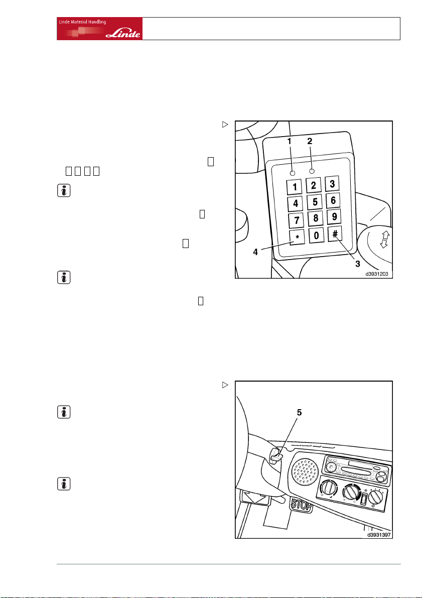
Truck data acquisition - special setting
(PIN number)
Logging in and starting the truck:
¾ Engage the parking brake.
¾ Press any key to take the terminal into oper-
ation.
The green LED (2) flashes.
0
¾ Enter your PIN number (factory s
0 0 0 0
).
NOTE
etting =
In case the incorrect PIN number was entered,
it can be corrected after pressing the key
*
(4)
with the asterisk.
#
e
¾ Confirm the entry by pressing th
Green LEDs (2) is illuminated steadily.
NOTE
(3) key.
If the red LED (1) comes on, an incorrect PIN
number was entered. Press the asterisk
*
(4)
and enter the correct number. After more than
three incorrect inputs (factory setting), the
red LED (1)and the green LEDs (2) flash. A
valid PIN input is disabled for 10 minutes. The
disable period can be terminated by entering a
special PIN number. Please contact your pool
manager.
¾ Turn the rotary knob (7) clock
possible and start the truck.
wise as far as
Operation 4
Special equipment
NOTE
If the truck does not start pro
tempt, the starting procedur
until the rotary knob (5) is r
the PIN number is deleted fro
the expiration of the delay p
NOTE
perly at the first at-
e can be repeated
eturned to zero and
m memory after
eriod.
If the green (2) and red ((1)) LEDs are both
illuminated steadily, the data must be read
out. Please inform your pool manager at once.
Turning the truck off and log
Operating Instructions – 393 807 1001 EN – 06/2006 67
ging out:
Page 78

4 Operation
Special equipment
¾ Turn the rotary knob (5) anticlockwise as far
as possible.
The engine is turned off.
NOTE
After an delay period (factory se
onds), the red LED (1) comes on b
then the green (2) and red (1) LE
about 3 seconds. During this ti
can be started any time. The LED
and the PIN number is deleted fr
The delay time can be set betwee
onds and 10 minutes with the dia
Please contact your authorise
Pressing the#(3) after the engine is turned
off terminates the delay period at once and the
PIN number is cleared.
tting = 10 sec-
riefly and
Ds flash for
me the truck
s then go out
om memory.
n10sec-
gnostic unit.
d dealer.
68 Operating Instructions – 393 807 1001 EN – 06/2006
Page 79

Working under load
Before taking up a load
Before taking up a load, check the load capacity diagram above the switch console on the
top right in the driver’s protective roof.
The max. permissible load is determined by
the distance of the centre of gravity of the load
from the fork back of the fork arms and the lift
height.
DANGER
The values specified in the lifting capacity diagram
or plate apply to compact homogeneous loads and
must not be exceeded as this will impair the stability
of the forklift truck and the strength of the fork arms
and lift mast.
When using attachments, observe the lifting capacity plate for each attachment device.
NOTE
Take the load restriction into account and consult your authorised dealer
•
before transporting off-centre or swinging
loads
•
before transporting loads with the lift mast
tilted forward or the load not close to the
floor
•
loads involving a large centre of gravity
distance
•
before using attachments and additional
equipment
•
before transporting loads in a wind force of
6andupwards.
Example
Load centre-of-gravity distance: 650 mm
Load height to be lifted: 6500 mm
¾ Trace a vertical line from a load distance of
650 mm to its point of intersection with the
line for a lift height of 6500 mm.
¾ At the point of intersection with the horizon-
tal line read off the max. permissible load to
the left.
The maximum load in this example is 1700 kg.
Operation 4
Working under load
t3921383
1 Max. weight of permissible loads in kg
2 Lift height in mm
3 Series designation of the forklift truck with
max. load capacity and lift mast series
4 Distance between centre of gravity of load
and fork back in mm
Operating Instructions – 393 807 1001 EN – 06/2006 69
Page 80

4 Operation
Working under load
The same procedure should be followed for
other lift heights und centre of gravity distances. The values calculated refer to both
fork arms and a uniformly distributed load.
Wheel-slide protection chains
CAUTION
Mounting wheel-slide protection chains alters the
wheel freedom and load capacity of the forklift truck
Before wheel-slide protection chains are mounted
the standard fork carriage must be replaced by a
special fork carriage that is installed 40 mm further
forward. All other load capacity data on the basic
load capacity diagram and on the additional load
capacity plate must be reduced by 100 kg. This
load capacity reduction remains necessary even if
wheel-slide protection chains are not fitted.
¾ In addition, attach plate (5) alongside the
basic load capacity diagram.
Adjusting the fork spread
NOTE
The load centre should be in the centre between the forks.
70 Operating Instructions – 393 807 1001 EN – 06/2006
Page 81

¾ Raise the fork quick-release levers(1).
¾ Move the forks further apart or closer to-
gether depending to the size of the load to
be lifted.
Make sure that both forks are equa
lly distant
from the truck centre.
¾ Allow the quick-release levers to engage in
a notch on the fork carriage.
Loading
DANGER
Increased danger of falling and being squeezed.
Standing on the lifted forks without the appropriate
cage protection is therefore prohibited.
Operation 4
Working under load
1
d3921429
DANGER
The loads must be picked up so that they do not
project beyond the loading area of the truck, and
will not fall over or off.
If needed, a load backrest (option) must be used.
DANGER
No persons are allowed to stand under the picked
up load when the load is raised.
Only drive with the load lowered and the mast tilted
back.
¾ Approach the load to be picked up carefully
and as exactly as possible.
Operating Instructions – 393 807 1001 EN – 06/2006 71
Page 82

4 Operation
Working under load
¾ Set the mast vertical.
¾ Lift or lower the fork carriage to the required
height.
¾ Drive carefully into the centre o
to be picked up. Carefully drive t
forward under the centre of the lo
the load contacts the fork-fac
while taking care not to dislod
loads.
¾ Lift the fork carriage until the load is clear of
the ground.
f the load
he truck
ad until
e, if possible,
ge adjacent
d3921430
¾ Observe the load/ov
(option) (2)in the c
DANGER
If the overload warning symbol comes on red during
lifting,
¾ lower the load at once.
¾ Check the admissible weight of the load using
the load capacity diagram.
¾ Backupthetruckuntiltheloadisclear.
¾ Tilt the mast back.
erload indicator light
omposite instrument.
Transporting a load
NOTE
In goods traffic, the sender must load and,
if necessary, secure the goods to be transported safely. Therefore pay attention to
proper stacking and make sure the packages,
pallets, etc are not damaged. The carrier is
responsible for safe loading.
2
d3921509
72 Operating Instructions – 393 807 1001 EN – 06/2006
Page 83

¾ Do not drive with a laterally displaced load
(eg with a sideshifter).
¾ Carry the load close to the ground.
¾ On inclines, always travel with t
hill, never drive or maneuvre acr
he load up-
oss a slope.
¾ Work with a guide if visibility is restricted.
¾ Iftheloadtobetransportedisstackedso
high that no unobstructed view in direction
of travel is ensured, the truck may only be
driven with the load trailing.
Unloading
DANGER
Never park the truck and leave it unattended with
theload/forkcarriageraised.
fork carriage ablassen TO forks on the ground aufliegen.
Operation 4
Working under load
d3921431
¾ Carefully approach the racking receiving
the load.
¾ Lift the fork carriage to the required height.
¾ Set the mast to the vertical position (load
horizontal).
¾ Note the mast position sensing symbol (1)
on the display if your truck is fitted with automatic mast positioning.
¾ Carefully drive into the racking.
¾ Carefully lower the load onto the racking
until the forks are free.
¾ Reverse the truck.
Operating Instructions – 393 807 1001 EN – 06/2006 73
1
d3921357
Page 84

4 Operation
Loading / Transport
Tow coupling
NOTE
The tow coupling is used only for towing light
trailers inside the plant. (Observe the applicable safety guidelines and VDI.)
¾ Turn the handle ((1)) of the tow pin 90° to
the rear and then lift it up.
¾ Place the drawbar eye into the c
sleeve (2).
¾ Press down the tow pin against spring pres-
sure, turn 90° degrees and let engage in the
retainer.
oupling
1
2
d3921373
Loading / Transport
Securing the hose reel against rewinding
If a single attachment is installed, a hose reel
(1) is installed underneath the floor plate (in
case of two attachments a mirror-inverted
second one (5) is also installed.
WARNING
The hose reels are spring-tensioned
and must always be secured against rewinding:
• Before the hose couplings at the mast union
can be disconnected (eg for removal of the
mast or the hose reel itself).
• Whenever the hose reels in the vehicle are
being serviced.
74 Operating Instructions – 393 807 1001 EN – 06/2006
Page 85

WARNING
Do not open the reel locking mechanism on the
removed hose reel.
If so, the spring tension must first be reduced to 0.
Please contact your authorised dealer.
¾ Open the bonnet.
¾ Open the floor plate and secure it.
¾ hex head screw (3) to the Hose reel (1) in
direction of travel right) with key (SW 10)
against the stop in gesicherte position (6)
turn.
The pawl (2) points opposite to the direction of
travel and the pin (8)is visible; the hose reel is
secured against turning.
Operation 4
Loading / Transport
5
1
¾ If two attachments are installed, also turn
the pawl (4) of the second hose reel (5) to
the locked position(6).
¾ Disconnect the hoses before removing the
mast.
CAUTION
If the mast is extended with the pawl in action, the
hose lines can not be damaged (ratchet effect).
When the mast is lowered again, however, the
hoses are not reeled in and can therefore suffer
damage.
The reel locking mechanism may only be released
after the mast has been installed (hoses reconnected). For this set the pawl(s) back to the free-wheeling position (7) (pawl visible).
Dismantling the lift mast
This work should only be performed by specialist staff working for your authorised dealer .
4
8
3
d3921481
2
3
d3921468
2
6
7
Operating Instructions – 393 807 1001 EN – 06/2006 75
Page 86

4 Operation
Loading / Transport
DANGER
The spring elements on the drive axle are pretensioned.
Before dismantling the tilt cylinders, the lift mast
must be tilted back 2 °.
DANGER
The lift mast may fall off during
transport.
Do not move under overhead loads!
¾ Fix the lifting gear to the traverse on the
outer mast of the lift mast at the top.
¾ When dismantling the lift mast, place the tilt
cylinders on a suitable piece of timber and
secure with a steel strap.
CAUTION
After dismantling the lift mast or tilt cylinders, the
potentiometer for the tilt angle is misaligned.
The potentiometer for the tilt angle thus has to be
readjusted after reinstalling the lift mast . When
doing so, the parking brake should be applied for
safety reasons, and any restriction in terms of the
tilt angle taken into account. Please contact your
authorised dealer.
d3921469
Driving without a mast
CAUTION
When driving without a mast the speed of the truck
should be reduced for safety reasons.
Before removing the mast, therefore, install an additional stop screw under the reverse accelerator
(double-pedal operation) or accelerator (single-pedal operation) to limit the truck speed.
¾ Shut the engine off.
76 Operating Instructions – 393 807 1001 EN – 06/2006
Page 87

¾ Install a M8 X 20 hex head screw (3) half as
high as the M8 hexagonal nut (2) (DIN 6330,
6331, 6334).
¾ Screw a hexagonal nut (2) on the existing
M8 hex head screw (1) until hex head screw
(3) contacts hex head screw (1).
¾ Lock the hexagonal nut (2).
¾ Remove the mast.
Remove the additional stop after the mast is
refitted.
loading
Lifting the truck with a crane
DANGER
When loading the truck by crane make sure no persons are within the working range of the crane! Do
not exceed the hoisting weight on the manufacturer’s plate.
Do not step under elevated loads. Only use lifting
slings and a crane of sufficient capacity.
Operation 4
Loading / Transport
3
2
1
d3921520
WARNING
When hoisting the truck with a crane the tilt cylinders and the cover plate at the counterweight can
get damaged.
Fully lower the mast, fully retract the tilt cylinders
and lift the truck with it slanting forward.
¾ Attach the lifting slings at the points pro-
vided.
The fastening points are not marked on your
truck.
Operating Instructions – 393 807 1001 EN – 06/2006 77
Page 88

4 Operation
Loading / Transport
¾ Place a round sling ((2)) (min. capacity 3000
kg) around the lower edge of the counterweight.
¾ Use edge protectors on sharp edges.
¾ Wrap a round sling ((3)) (3000 kg c
capacity minimum) around the cro
ber on the outer upright of the m
¾ Attach all the ends to the crane hook (1).
¾ Make sure the safety (4) is closed.
NOTE
When the truck is being hoisted, t
should not rub against the sides
head guard and any attachments p
fitted.
arrying
ss mem-
ast.
he slings
of the over-
ossibly
Hoisting the truck with lifting
CAUTION
If the truck is not hoisted vertically, the eyebolts can
break off.
The truck may be hoisted with eyebolts only if the
appropriate lifting gear (3) is used with which the
chains (2, 6) lead straight up from the eyebolts (1,
7).
¾ Hook the chains (6) (min. capacity 3000 kg)
into the eyebolts (7) at the counterweight.
¾ Hook the chains (2) (min. capacity 3000 kg)
into the eyebolts (1) at the mast.
¾ Make sure the safety(5) is closed.
NOTE
eyes
When the truck is being hoisted, the slings
should not rub against the sides of the overhead guard and any attachments possibly
fitted.
78 Operating Instructions – 393 807 1001 EN – 06/2006
Page 89

Transport with lorry or low-bed trailer
¾ Lower the mast.
¾ Engage the parking brake.
¾ Chock the truck.
¾ Tie the truck down.
Operation 4
Loading / Transport
d3921499
Before leaving the t
¾ Deposit the load or l
¾ Tilt the mast slightly forward.
The forks must contact the ground.
¾ Pull the parking brak
¾ Shut the engine off.
¾ Removetheignitionkey(2).
ruck unattended
ower the fork carriage.
e handle (1) up.
d3921432
1
2
Operating Instructions – 393 807 1001 EN – 06/2006 79
Page 90

4 Operation
Loading / Transport
80 Operating Instructions – 393 807 1001 EN – 06/2006
Page 91

5
Servicing
Page 92

5 Servicing
Inspection and maintenance overview
Inspection and maintenance overview
General information
Your truck will remain operational only if the
maintenance and checks are carried out
regularly and according to the information
and instructions in the operating manual.
The maintenance may only be performed
by qualified authorised personnel. This work
can be carried out by your authorised dealer
under a service contract.
Ifyouwishtodotheworkyourself,werecommend that the first three customer service
checks be carried out by your distributor’s
mechanic in the presence of the responsible
mechanic in your workshop so that your staff
can receive the appropriate instruction.
When servicing the truck, it m
a level surface and the wheels
the engine and remove the igni
When working on the truck with the fork
carriage and mast elevated, secure them
against inadvertent lowering.
When working on the front part of the truck,
secure the mast against tilting back.
No changes, particularly no m
additions, may be made to the t
the approval of the manufactu
Perform a functional check and trial run after
every servicing.
WARNING
Possibly fitted side doors can close during the
servicing, so that personnel can get caught in the
door.
Fort this reason both doors must be opened and
secured against closing.
ustbeplacedon
secured. Stop
tion key.
odifications and
ruck without
rer.
The truck must always be properly labelled.
Missing or damaged type plates and/or self-adhesive labels must be replaced. Refer to the parts
catalogue for their location and part number.
Follow the precautions for handling fluids and
lubricants.
When operating the truck under extreme
conditions (ie extreme heat or cold, very dusty
environment, etc), the intervals given in the
maintenance schedule should be reduced
accordingly.
Maintenance intervals
Under certain conditions it is possible to
change the intervals of certain services listed
in the maintenance schedule. Please use
the specified engine oil and coolant in this
case. The required qualities are specified
in the recommended lubricants section.
The inspection and maintenance intervals
depend on the operating and duty conditions
of the truck. Under heavy-duty conditions we
recommend shorter intervals. Please contact
your authorised dealer.
CAUTION
ENVIRONMENT NOTE
NOTE
82 Operating Instructions – 393 807 1001 EN – 06/2006
Page 93

Work on the mast and front part of the truck
DANGER
When working on the front part of the truck, there
is a danger of getting squeezed in and of the mast
lowering accidentally.
Before carrying out any work on the raised mast
and fork carriage, be sure that the following safety
precautions are observed. These safety precautions are only sufficient for the general maintenance
on your truck (inspections and lubrication services).
For repairs (eg replacement of chains or removal
of the lift cylinder) further safety precautions are
required. Please contact your authorised dealer.
Securing against tilting back
The mast must be secured against tilting back
accidentally.
¾ Tilt the mast back completely.
¾ Shut the engine off.
¾ Remove the ignition key.
Standard mast
METHOD OF OPERATION: When the inner upright is lifted, the chain pulleys are also
moved upwards thereby raising the fork carriage at a 2:1 ratio.
Servicing 5
Inspection and maintenance overview
Securing the raised standard mast
DANGER
Check the chain load capacity.
Choose a chain with a sufficient load capacity for
the mast in question. Do not exceed the maximum
height of lift.
¾ Extend the mast.
Operating Instructions – 393 807 1001 EN – 06/2006 83
d3921437
Page 94

5 Servicing
Inspection and maintenance overview
¾ Fasten the chain around the cross member
of the outer upright (1) and the cross member of the inner upright(2).
¾ Lower the inner upright until it is held by the
chain.
Duplex mast
NOTE
The advantage of this mast vers
the special free lift height ca
in spaces with a low ceiling (ce
ships).
METHOD OF OPERATION: The fork carriage
is raised to the special free lift height by the
centre cylinder via the chain pulley. It moves
at twice the rate of the centre cylinder. The
inner upright and the fork carriage are then
raised together by the two outer cylinders. The
centre cylinder is mounted on the extendible
inner upright.
Securing the raised duplex mast
DANGER
Check the chain load capacity.
Choose a chain with a sufficient load capacity for
the mast in question. Do not exceed the maximum
height of lift.
ion is that
nbeusedeven
llars, wagons,
1
2
d3921482
¾ Extend the mast.
84 Operating Instructions – 393 807 1001 EN – 06/2006
Page 95

¾ Fasten the chain around the cross member
of the outer upright (1) and the cross member of the inner upright(2).
¾ Lower the mast until it is held by the chain.
¾ Fully lower the fork carriage.
Triplex mast
METHOD OF OPERATION: The fork carriage
is raised to the special free lift height by the
centre cylinder via the chain pulley. Then the
two lift cylinders raise the inner upright. When
the inner upright is fully extended, two further
lift cylinders raise the intermediate upright,
which is raised together with the inner upright and fork carriage. The centre cylinder is
mounted on the extendible inner upright.
Securing the raised triplex mast
DANGER
Check the chain load capacity.
Choose a chain with a sufficient load capacity for
the mast in question. Do not exceed the maximum
height of lift.
Servicing 5
Inspection and maintenance overview
1
2
d3921483
¾ Extend the mast.
¾ Fasten the chain around the cross member
of the outer upright(1) and of the intermedi-
1
ate upright(2).
¾ Lower the mast until it is held by the chain.
¾ Fully lower the fork carriage.
2
d3921484
Operating Instructions – 393 807 1001 EN – 06/2006 85
Page 96

5 Servicing
Inspection and maintenance overview
Initial operation
¾ Check the engine oil level
¾ Check the coolant level in the expansion
reservoir
¾ Refuelling
¾ Check condition, electrolyte level and acid
density of the battery
¾ Check the tyre inflation pressure
¾ Tighten the wheel nuts
Checks before starting work
¾ Check the fuel level
¾ Check the engine oil level
¾ Check the hydraulic oil level
Maintenance after the first 50 hours
¾ Check the parking brake for proper opera-
tion.
¾ Tighten the wheel fasteners.
¾ Check the hydraulic system, drive axle,
hydraulic pumps and lines for leaks (visual
inspection).
¾ Check the hydraulic oil level
¾ Check the brake system
¾ Check the steering system
¾ Check the lifting device and attachments
¾ Regenerate the soot filter (option)
¾ Check the third auxiliary hydrau
and safety system
¾ Check the coolant level
¾ Check the tyre pressures
¾ Check the mast, lift chain, lift cylinder and
stops for condition, security and proper
operation.
¾ Clean the lift chain, adjust a
chain spray.
¾ Check the electric lines and cable connec-
tions for condition and security.
¾ Drain water from the fuel filter.
lic function
nd lubricate with
Inspection and maintenance as required
¾ Clean the lift truck
¾ Wheel change
¾ Clean the vent hose to the fuel tank
¾ Clean and lubricate the lift chains
¾ Renew the air filter element (
hours minimum)
¾ Renew the air filter safety element (every
3000 hours minimum)
¾ Check the dust discharge valve
¾ Clean the prefilter
86 Operating Instructions – 393 807 1001 EN – 06/2006
every 1000
¾ Drain the fuel filter
¾ Regenerate the soot filter
¾ Clean and check the radiator and hydraulic
oil cooler for leaks
¾ Change the oil in the oil bath air cleaner
¾ Tighten the wheel fasteners w
ers (after each servicing or r
100 hours minimum)
¾ Check the tyres for damage and foreign
objects
heel fasten-
epair, every
Page 97

Servicing 5
Inspection and maintenance overview
¾ Lubricate the steering axle bearings (every
1000 hours minimum)
¾ Check the lap seat belt for condition and
proper operation
¾ Service the air conditioner
Inspection and maintenance work every 500 to 1000 operating hours * or every year
¾ Change motor oil (once a year at least)
¾ Change motor oil filter (onc
¾ Check coolant concentration
¾ Hydraulic system: Check oil level
¾ Check bleed valve on hydrauli
proper operation
¾ Change fuel filter
¾ Check function of control unit
¾ Check fastening of frame, tilt c
steering axle
¾ Check fastening of axle clamps and wheel
motors
¾ Check and lubricate pedals
¾ Check condition of ribbed V-belt
¾ Check condition and tension of toothed belt,
replace if necessary
¾ Clean water and hydraulic oil cooler
¾ Check particulate filter system
¾ Check condition of electric cables, cable
connectors and connections and that they
are securely fitted
¾ Battery: Check condition, acid level and
electrolyte density (even for maintenancefree battery)
¾ Check and lubricate other bearing
joints
e a year at least)
c tank for
ylinders and
sand
¾ Clean and lubricate steering axle
¾ Sideshift: Clean and lubric
fastening
¾ Fork adjustment device: Clean and lubri-
cate, check fastening
¾ Check fork arms and arm safety devices
¾ Check condition of lift mast,
lift cylinders and end stops,
secure fastening and proper o
¾ Adjust lift mast chain, spray with chain spray
¾ Change air-cleaner cartridge, check vac-
uum-operated switch
¾ Check condition of motor brack
mounting and check for secure a
¾ Check intake and exhaust lines for signs of
leaks
¾ Check hydraulic system for signs of leaks
¾ Check parking brake for proper
¾ Check fastening of steering cylinder and
steering-knuckle pin
¾ Check and adjust side stops on drive axle
¾ Check pretension of double hoses
¾ Clean oil bath air cleaner
* Depending on fuel, coolants and lubricants,
driving style and service conditions. Refer
also to Recommendations for fuel, coolant
and lubricants.
ate, check
lift mast chain,
also check for
peration
et and motor
ttachment
operation
Inspection and maintenance every 3,000 operating hours or every 2 years
¾ Change feed / pressure / suction filter and
breather of hydraulic system
Operating Instructions – 393 807 1001 EN – 06/2006 87
¾ Change ribbed V-belt
¾ Change safety cartridge of air f
ilter
Page 98

5 Servicing
Inspection and maintenance overview
¾ Check tilt cylinder bearing for wear
¾ Check drive axle bearing for wear
¾ Hydraulic pump on engine: check f
Inspection and maintenance e
¾ Renew the hydraulic oil
Inspection and maintenanc
¾ Change the coolant pump ¾ Change the coolant G12
Inspection and mainten
Assembly
Nr.
Engine Engine oil
1
2 Fuel tank Diesel
3
Cooling system Antifreeze / drinking water
4 Hydraulic system Hydraulic oil
Battery
5
Tyres
6
7
Wheel fasteners,
8
Lift chains / mast channels
Air conditioning
9
astening
very 6000 hours or every 3 years
e every 9000 hours or every 4 years
ance data
Aids / fluids and lubricants
Distilled water As needed
Air
tighten
Linde chain spray As needed
Refrigerant
¾ Change toothed belt and tension pulley (at
latest after 5 years)
¾ Check slide guides on sideshift for wear
¾ Check fork arm adjustment device
and tear
Filling capacity / settings
With heater / air conditioning
conditioning approx. 9.0 L
Height of lift up to 5000 mm
Height of lift from 5000 mm
to 6900 mm approx. 25.5 L
Height of lift from 6900 mm
to 8000 mm approx. 28.0 L
See sticker on inside of
for wear
approx. 4.5 L
approx. 40.0 L
approx. 11.0 L
Without heater / air
approx. 24.0 L
overhead guard
Front: 170 Nm
Rear: 460 Nm
1600 g
88 Operating Instructions – 393 807 1001 EN – 06/2006
Page 99

Consumable materials recommendations
Diesel fuel
Only diesel fuels to EN 590 with a cetane
number (CN) not less than 51 may be used.
The fuel sulphur content must not exceed
350 mg/kg.
If the only diesel fuel availab
content above the value permis
EN 590, the engine oil change in
be reduced as follows:
• At a sulphur content more than 350 mg/kg
and less than 2000 mg/kg = engine oil
change interval 300 operating hours.
• At a sulphur content more than 2000 mg/kg
= engine oil change interval 150 operating
hours.
NOTE
If the sulphur content of the diesel fuel is
more than 350 mg/kg, as well as performing
oil changes more frequently, an oil to VW
standard 505 00 / 505 01 / 506 00 / 506 01
must be used.
NOTE
As the ambient temperature fall
characteristics of diesel fuel
paraffin segregation. If "summ
are used at low ambient temper
can lead to problems. Therefo
colder part of the year cost-r
diesel fuels are available, w
be used at temperatures down t
In winter, use only winter diesel fuel, so
that the fuel lines do not become blocked
with segregated paraffin waxes. At very
low temperatures even winter diesel fuel
can suffer from this problem of segregation.
Please contact your authorised dealer.
CAUTION
When using bio-diesel fuel (RME to DIN 51606/provisional standard), some important points must be
considered.
Please contact your authorised dealer.
le has a sulphur
sible for
tervals must
s, the flow
s reduces due to
er" diesel fuels
atures, this
re during the
esistant "winter"
hich can reliably
o about -22 °C.
Servicing 5
Inspection and maintenance overview
Hydraulic oil
NOTE
The working temperature is the critical factor
to be considered in selecting the correct oil for
hydrostatic drives. The recommendations for
oils given below can only be taken as guide
values.
Hydraulic oil recommendations for standard
use:
Hydraulic oil ISO - L - HM 68 to ISO 6743 - 4 or
HLP ISO VG 68 to DIN 51524.T.2 (factory
filling) average sustained oil temperature
60 °C - 80 °C.
Hydraulic oil recommendations for heavy-duty
use:
Hydraulic oil ISO - L - HM 100 to ISO 6743 - 4
or HLP ISO VG 100 to DIN 51524, T.2 for
heavy-duty and multi-shift use, operation in
hot climates or at high ambient temperatures,
average sustained oil temperature over 80 °C.
Hydraulic oil recommendations for normal and
heavy-duty use:
Hydraulic oil ISO - L - HV 68 to ISO 6743 - 4
or HVLP ISO VG 68 to DIN 51524, T.3 (multigrade oil)
Bio-hydraulic oil
Highly biodegradable hydraulic fluid
Aral Forbex SE 46
CAUTION
Bio-oils must not be mixed with mineral-based oils.
No recommendations for other fluids from other
manufacturers can be made at the present time.
NOTE
If in doubt, we recommend obtaining the advice of your authorised dealer. Recommendations made by representatives from the
mineral oil industry should also be agreed with
Operating Instructions – 393 807 1001 EN – 06/2006 89
Page 100

5 Servicing
Inspection and maintenance overview
your authorised dealer. Manufacturer’s approval has been granted only for the oils listed
above. If they are mixed with other hydraulic
fluids or other hydraulic fluids are used, highly
expensive damage may result.
Lubricating grease
Linde heavy-duty grease, lithium-saponified
with EP active ingredients and MOS
ignation as per DIN 51825-KPF 2N-20 (order
no. see spare parts list).
Mixing with lubricating greas
soap basis other than lithium i
.Des-
2
etypeswitha
s not permitted .
Coolant
CAUTION
Refer to the coolant specifications!
Use only coolant G12 A8D to VW specification
TL-VW 774D (factory filling) or G 12 A8F to VW
specification TL-VW- 774F.
Temperature
25°C 40 % 60 %
30°C 45 % 55 %
35°C 50 % 50 %
40°C 60 % 40 %
Coolant
additive
Drinking
water
Long life engine oils to VW standard 506 00 or
506 01. These oils are available exclusively in
viscosity SAE 0W-30.
Oil change every 1000 hours or every 12
months
The engine is factory-filled wit
engine oil for 1000 operating h
Engine oil for oil change every 500 operating
hours
Engine oils to VW standard 505 00 and 505 01
are approved. For viscosity see table.
This engine oil must be changed eve
erating hours.
Engine oil for oil change every 300 operating
hours
Engine oils of qualities API CD and
ACEA B2 / B3, together with high-quality
API-C and ACEA-B classes are also approved. Viscosity - see table
This engine oil must be changed ev
erating hours.
¾ When topping up the various oils may be
mixed with each other, however the oil
change interval is then determined by the
oil of the lowest quality.
h a good quality
ours.
ry 500 op-
ery 300 op-
Refrigerant for air conditioning system
R134a
Battery grease
Acid-free lubricating grease (terminal grease).
Chain spray
Linde chain spray (order no. see spare parts
list).
Engine oil
Specification and viscosity of engine oil for oil
change every 1000 operating hours
90 Operating Instructions – 393 807 1001 EN – 06/2006
Since a good engine oil is a pre-requisite for
problem-free operation and a long working
life for the engine, use only good quality
engine oil even when topping up and also
at oil change . Due to their limited viscosity
 Loading...