


User and maintenance instructions
FlowMaster II rotary driven electric pump (24V DC)
Model 85859, series “A”
Date of issue |
August 2016 |
|
|
Form number |
404696A |
Read manual prior to installation or use of this product. Keep manual nearby for future reference.
Contents |
|
Safety . . . . . . . . . . . . . . . . . . . . . . . . . |
2 |
Explanation of safety signals . . . . . . . |
2 |
Overview. . . . . . . . . . . . . . . . . . . . . . . |
2 |
Maintenance and repair . . . . . . . . . . . |
3 |
Safety
Read and carefully observe these installation instructions before installing, operating or troubleshooting the referenced equipment. Referenced equipment must be installed, maintained and repaired exclusively by persons familiar with the instructions.
Always disconnect power source (electricity, air or hydraulic) from equipment, if applicable, when it is not being used.
Adequate personal protection must be used to prevent material from contacting the skin or eyes.
If any luid appears to penetrate the skin, seek medical treatment immediately. Do not treat injury as a simple cut.Tell attending physician exactly what luid was injected. Failure to comply may result in personal injury and/or damage to equipment.
Any other use not in accordance with instructions will result in loss of claim for warranty or liability.
•Never exceed maximum speciication ratings of the equipment.
•Do not misuse, modify parts, or use worn and/or damaged parts.
•Always read and follow the manufacturer’s recommendations regarding the use of protective clothing and equipment.
Explanation of safety |
Overview |
|||
signals |
|
|
Model 85859 is a FlowMaster II rotary |
|
|
|
|
|
driven pumping unit designed to operate |
|
|
|
|
a Centro-Matic lubrication system. |
|
|
|
|
The pump includes motor speed control |
|
DANGER |
|
|
|
|
Indicates a hazardous situation which,if not |
and built in circuit protection to prevent |
||
|
avoided, will result in death or serious injury. |
control burnout.The pump is double acting, |
||
|
|
|
|
dispensing lubricant on both “up” and |
|
|
|
|
“down” strokes.The model 85859 also |
|
|
|
|
includes: |
|
WARNING |
|
|
|
|
Indicates a hazardous situation which,if not |
|
||
|
avoided will result in death or serious injury. |
• A 2 in. (50,8 mm) follower plate. |
||
|
|
|
|
• An electric loat switch. |
|
|
|
|
• A vent valve for relieving line pressure to |
|
|
|
|
recharge the injectors. |
|
CAUTION |
|
|
|
|
Indicates a hazardous situation which,if not |
• A mechanical shut-off valve. |
||
|
avoided, could result in minor or moderate |
|
||
|
injury. |
|
|
This unit is for use with SL-V, SL-1, SL-11, |
|
|
|
|
|
|
|
|
|
|
|
|
|
|
SL-32 and SL-33 series injectors. |
|
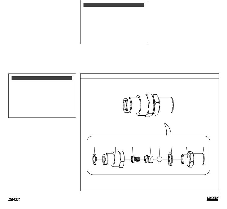
Mechanical shut-off valve speciications |
|
||
|
Maximum operating |
6 000 psi |
Mechanical shut-off valve |
|
|
pressure |
(413,6 bar) |
The mechanical shut-off valve automatically |
|
|
Operating temperature |
–40 to +150 °F |
||
|
Port shut-off body |
(–40 to +65 °C) |
shuts off the illing of the reservoir without |
|
|
1/2 NPTF |
power applied to the system. |
||
|
|
|
|
|
|
|
|
|
As grease lows through the valve and into |
|
|
|
|
the reservoir, the follower raises until it con- |
|
|
|
|
tacts the pivot arm. The pivot arm then rai- |
|
|
|
|
|
|
|
|
|
ses until it contacts the pin on the shut-off |
|
|
|
|
valve and closes the valve.When the valve |
|
|
|
|
closes, the low of the grease to the reservoir |
|
|
|
|
stops. |
|
|
|
|
Shut off the ill pump and relieve pressure |
|
|
|
|
between the ill pump and the shut-off valve |
|
|
|
|
in order to disconnect the ill line safely. |
|
|
|
|
Keep the pressure relief valve activated |
|
|
|
|
until the supply line pressure on the gauge |
|
|
|
|
falls below 200 psi (13 bar). The ill line can |
|
|
|
|
then be removed at the quick disconnect |
|
|
|
|
point. |
System speciications |
|
Supply voltage |
24V DC |
Ambient operating |
–40 to +150 °F |
temperature |
(–40 to +66 °C) |
Container capacity |
90 lb (41 kg) |
2
Installing the pump
Locate unit so that electric power connection is accessible.
1Mark center locations of the six holes at the bottom of the reservoir.
2Drill six 1/2 in (13 mm) holes. Use 7/16 in (11 mm) bolts for added lexibility in securing reservoir to the equipment.
3Connect lubricant outlet of pump to system with suitable hose capable of
3 500 psi (241 bar) working pressure.
Bare pump assembly
Refer to 85738 operation manual 404517 for setting pump speed on 24V DC motor.
Filling reservoir
To bulk ill reservoir, attach the supply line to port "P" on shut off valve. Refer to
igure 3, page 5 and verify system is connected and start ill pump.
When reservoir is full, shut-off valve will close. Grease in ill line will be under high pressure. Relieve grease pressure before disconnecting ill hose by opening pressure relief valve.
Refer to Filling reservoir with optional |
System malfunction |
278552 bypass manifold assem- |
|
bly, page 5. |
Refer to Troubleshooting, page 6 for deter- |
|
mining common problems and solutions. |
Maintenance and repair
General maintenance
•Keep area around pump and illing port clean, as lubricants attract dirt and debris.
•Keep lubricants free of contaminants.
WARNING
Do not perform maintenance or service on assembly with any power source connected.
Failure to comply can cause death and/or serious personal injury.
Outlet check service
Refer to ig. 1. The pump will not build up suficient lubricant pressure if the outlet check assembly (5) is fouled. Foreign material may lodge beneath the steel ball (47) or between check bushing assembly (44) and the seat of pump check disc assembly (43). Sealing surfaces of seat must fully seal.
1 Remove hose assembly (11).
2Remove entire outlet check bushing (5), street elbow (6) and adapter (4).
3Remove elbow (6) and adapter (4) from outlet check bushing (5).
4Remove outlet connector (48) from check bushing assembly (44).
5Remove pump check disc assembly (43) from outlet connector (48).
6Inspect all check components (43, 44, 45, 47) for presence of foreign material,
scoring and or other damage, that may cause internal leakage. Replace components if damage is found.
7Replace gaskets (29) and (46) whenever outlet pump check disc assembly (43) is disassembled.
WARNING
Do not over-ill reservoir. Extreme pressure can damage reservoir.
Failure to comply can cause death and/or serious personal injury.
|
|
|
|
|
|
|
Fig. 1 |
Outlet check assembly (5) |
|
|
|
|
|
|
|
|
|
|
|
|
|
|
1/4 IN |
29 |
44 |
43 |
45 |
47 |
46 |
48 |
NPTF |
|
3 |
|
|
|
|
|
|
8For assembly, torque outlet connector (48) and check bushing assembly (44) to
100 ft-lbf (13.5 Nm).
Upon reassembly, tighten to 10 ft. lbf. (13.5 Nm). Safety unloader is preset and non-adjustable.
4Loosen and remove nuts (56) and weighted follower plate (57) on top of the follower.
5 Remove and replace follower foam (55).
Safety unloader valve |
Follower |
Refer to ig. IPB1, page 7. If pressure switch fails to operate, safety unloader (15) activates at 3 750 to 4 250 psi (259 to 293 bar) lubricant pressure to relieve supply line pressure. Safety unloader (15) is not serviceable and must be replaced if malfunctioning occurs.
WARNING
Do not operate without safety unloader installed.
If not installed, install safety unloader before using pump.
Failure to comply may result in death or serious personal injury.
WARNING
Do not plug outlet of safety unloader. Plugging safety unloader outlet will result in pressure build up.
Failure to comply may result in death or serious personal injury.
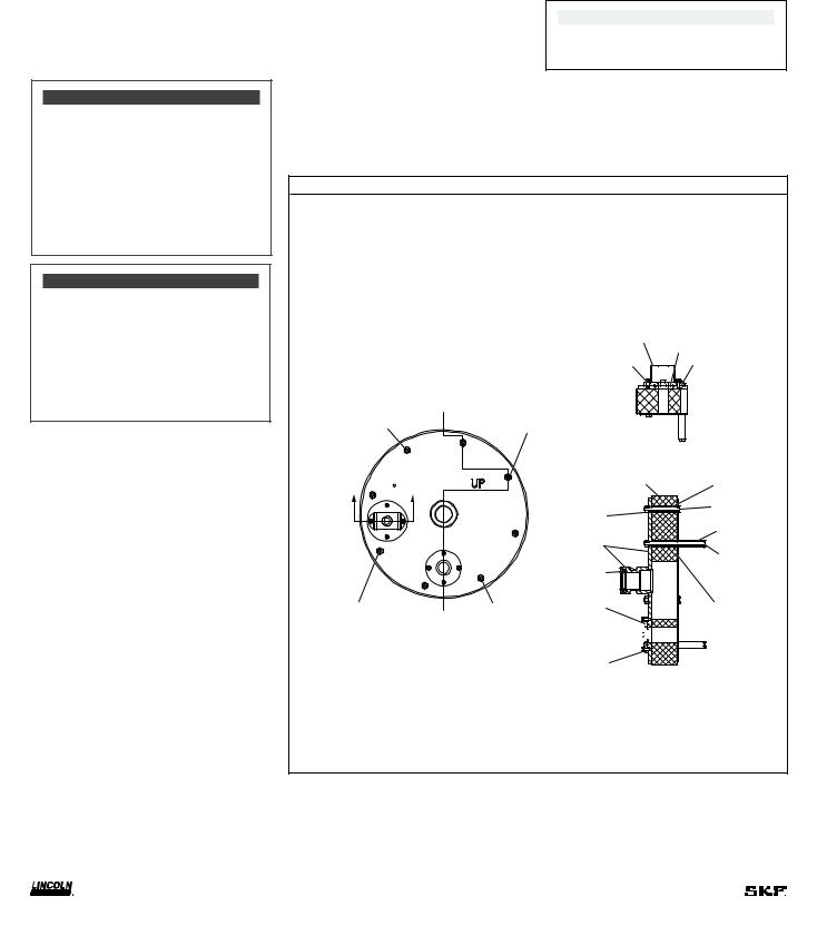
Refer to († ig. 2) and († ig. IPB 1, page 7). Service unit if follower foam is damaged or fails to wipe sides of reservoir effectively.
1Remove bolts (17) and lock washers (18) attaching the cover to the reservoir.
2Lift the entire pump, vent valve and cover assembly out of the reservoir.
3Remove the entire follower assembly from the reservoir (37).
NOTE
For assembly, install long bolts staggered with short bolts as shown.
Fig. 2
Follower assembly (24)
51
53
52 54
LONG SCREW |
LONG SCREW |
55 |
61 |
|
|
||
56 |
62 |
|
61 |
||
|
||
57 |
63 |
|
|
||
58 |
|
LONG SCREW |
LONG SCREW |
59 |
64 |
|
|
60

52
4
 Loading...