


Lincoln 1116-080-A, 1132-080-A, 1133-08H-A, 1161-080-A, 1130-08H-A User Manual
...SERVICE MANUAL
(DOMESTIC)
IMPINGER CONVEYOR OVENS
MODEL
1116-080-A, 1116-080-A1, 1117-080-A, 1117-080-A1, 1130-080-A, 1130-080-A1, 1131-080-A, 1131-080-A1, 1132-080-A, 1132-080-A1, 1133-080-A, 1132-080-A1, 1130-08H-A, 1131-08H-A, 1132-08H-A, 1133-08H-A, 1161-080-A, 1162-080-A
WITH PUSH BUTTON CONTROLS
Lincoln Foodservice Products, LLC
1111 North Hadley Road
Fort Wayne, Indiana 46804
United States of America
Phone: (800) 374-3004
U.S. Fax: (888) 790-8193 • Int’l Fax: (260) 436-0735
Technical Service Hot Line
(800) 678-9511
www.lincolnfp.com
Imp2DigAdvServ |
REV 3/20/08 |

SEQUENCE OF OPERATION
IMPINGER II ADVANTAGE, GAS
(OVENS WITH PUSH BUTTON CONTROLS)
MODEL 1116-080-A |
NAT. GAS |
120VAC |
60 HZ. 1 PHASE |
|
MODEL 1116-080-A1 |
NAT. GAS |
120VAC |
60 HZ. 1 PHASE |
|
MODEL 1117-080-A |
LP GAS |
120VAC |
60 HZ. |
1 PHASE |
MODEL 1117-080-A1 |
LP GAS |
120VAC |
60 HZ. |
1 PHASE |
POWER SUPPLY
CONTROL BOX AUTO COOL DOWN
MAIN FAN CIRCUIT
BURNER CIRCUIT
IGNITION CONTROL
TEMPERATURE CONTROL
CONVEYOR DRIVE
Electrical power is supplied to the oven by a three-conductor cordset. Voltage from the black conductor to the white conductor is 120VAC.
Black conductor is hot White conductor is neutral. Green conductor is ground.
When the temperature in the control box reaches 120°F ± 3° (48.9°C ± 1.7°), the cooling fan thermostat will switch power to the control box cooling fans. The thermostat will interrupt power to the cooling fans when the control box temperature falls to 100°F ± 3° (37.8°C ± 1.7°).
Power is permanently supplied, through a 10 amp fuse, to the normally open main power switch. Power is also supplied to the normally open cooling fan thermostat. Closing the main power switch supplies 120VAC to the main fan motor, the cooling fan motors, the primary of the control transformer, the conveyor motor and to the ignition control.
Closing the main power switch supplies 120VAC to the burner blower motor. 120VAC is also supplied, through the main fan centrifugal switch (this switch closes when the main fan reaches approx. 1600 RPM) and the normally closed oven cavity hi-limit thermostat, to the primary of the burner transformer. 120VAC is also supplied to the oven control.
The ignition control operates on both 24VAC and 120VAC. When the control is energized by 24VAC from the transformer, 120VAC is switched by the ignition control to the hot surface igniter for 45 seconds for the hot surface igniter warm up. The igniter glows red, 24VAC is switched to the gas valve, which opens, and ignition should now occur.
Closing the main power switch supplies 120VAC to the primary of the oven control transformer. Secondary voltage, 24VAC, is supplied to the oven control. The oven control is set to desired temperature. The thermocouple will provide varying millivolts to the oven control. The oven control supplies 120VAC to the temperature regulation valve at intermittent intervals to maintain the desired temperature. The display on the oven control will indicate when the temperature regulation valve is energized.
NOTE: The display also indicates oven temperature.
Closing the main power switch supplies 120VAC to the conveyor motor and to the primary of the control transformer. Secondary voltage, 24VAC, is supplied to the oven control. Setting the oven control to the desired time outputs voltage, through a reversing switch, to the conveyor motor.
NOTE: The conveyor system uses a hall effect sensor and magnet to prove operation of the conveyor motor. If the conveyor motor is not running, “BELT JAM” is indicated on the display.
2 |
Impinger II – Advantage Digital Express Service Manual - Domestic |

SEQUENCE OF OPERATION
IMPINGER II ADVANTAGE, ELECTRIC (OVENS WITH PUSH BUTTON CONTROLS)
|
1130-080-A |
120/208VAC |
60 HZ. |
1 PHASE |
|
|
1130-080-A1 |
120/208VAC |
60 HZ. |
1 PHASE |
|
|
1130-08H-A |
208 VAC |
60 HZ. |
1 PHASE |
|
|
1131-080-A |
120/240VAC |
60 HZ. |
1 PHASE |
|
|
1131-080-A1 |
120/240VAC |
60 HZ. |
1 PHASE |
|
|
1131-08H-A |
240 VAC |
60 HZ. |
1 PHASE |
|
|
1132-080-A |
120/208VAC |
60 HZ. |
3 PHASE |
|
|
1132-080-A1 |
120/208VAC |
60 HZ. |
3 PHASE |
|
|
1132-08H-A |
208 VAC |
60 HZ. |
3 PHASE |
|
|
1133-080-A |
120/240VAC |
60 HZ. |
3 PHASE |
|
|
1133-080-A1 |
120/240VAC |
60 HZ. |
3 PHASE |
|
|
1133-08H-A |
240 VAC |
60 HZ. |
3 PHASE |
|
|
1161-080-A |
120/240VAC |
60 HZ. |
1 PHASE |
|
|
1162-080-A |
120/208VAC |
60 HZ. |
3 PHASE |
|
|
|
Electrical power to be supplied to the oven by a three conductor service for |
|||
|
POWER SUPPLY |
||||
|
|
single phase and a four conductor service for three phase. |
|||
|
|
Black conductor is hot. |
|
|
|
|
|
Red conductor is hot. |
|
|
|
|
|
Orange conductor is hot (used for three phase only). |
|||
|
|
White conductor is neutral. |
|
|
|
|
|
Green conductor is ground. |
|
|
|
|
CONTROL BOX AUTO |
When the temperature in the control box reaches 120°F ± 3° (48.9°C ± 1.7°), the |
|||
|
COOL DOWN |
cooling fan thermostat will switch power to the control box cooling fans. The |
|||
|
|
thermostat will interrupt power to the cooling fans when the control box |
|||
|
|
temperature falls to 100°F ± 3° (37.8°C ± 1.7°). |
|||
|
MAIN FAN CIRCUIT |
Power is permanently supplied through the 10 amp fuses, through the normally |
|||
|
|
closed oven cavity hi-limit thermostat, to the normally open main power switch. |
|||
|
|
Power is also supplied to the normally open cooling fan thermostat. Closing the |
|||
|
|
main power switch energizes the coil of the oven start relay, it’s contacts close |
|||
|
|
enabling the 20 minute time delay relay. The 20 minute time delay relay supplies |
|||
|
|
120VAC to the oven fan relay, these normally open contacts now close |
|||
|
|
supplying 208/240VAC to the main fan motor. 120VAC is also supplied to the |
|||
|
|
cooling fans. 208/240VAC is supplied to the primary of the control transformer, |
|||
|
|
the conveyor motor and, through the air pressure switch, to the oven control. |
|||
|
TEMPERATURE CONTROL |
Closing the main power switch supplies 208/240VAC to the primary of the |
|||
|
|
control transformer. Secondary voltage, 24VAC, is supplied to the oven control. |
|||
|
|
The oven control is set to desired temperature. The thermocouple will provide |
|||
|
|
varying millivolts to the oven control. The oven control supplies 208/240VAC to |
|||
|
|
the coil of the heater relay at intermittent intervals to maintain the desired |
|||
|
|
temperature. The display on the oven control will indicate when the heater relay |
|||
|
|
is energized. |
|
|
|
|
|
NOTE: The display also indicates oven temperature. |
|||
|
CONVEYOR DRIVE |
Closing the main power switch supplies 208/240VAC to the conveyor motor and |
|||
|
|
to the primary of the control transformer. Secondary voltage, 24VAC, is supplied |
|||
|
|
to the oven control. Setting the oven control to the desired time outputs voltage, |
|||
|
|
through a reversing switch, to the conveyor motor. |
|||
|
|
NOTE: The conveyor system uses a hall effect sensor and magnet to prove |
|||
|
|
operation of the conveyor motor. If the conveyor motor is not running, “BELT |
|||
|
|
JAM” is indicated on the display. |
|
||
|
AUTOMATIC COOL DOWN |
When the oven is started, the time delay relay timing circuit is enabled, |
|||
|
|
permitting the oven fans to run approximately 20 minutes after the oven is shut |
|||
|
|
off, to cool the oven. The time delay relay will keep the coil of the fan relay |
|||
|
|
closed, maintaining operation of the main fan and cooling fans. |
|||
Impinger II – Advantage Digital Express Service Manual - Domestic |
3 |
||||

SCHEMATIC DIAGRAM
MODEL 1116-080-A, 1116-080-A1, 1117-080-A, 1117-080-A1
4 |
Impinger II – Advantage Digital Express Service Manual - Domestic |
SCHEMATIC DIAGRAM
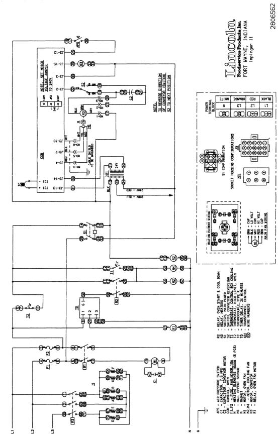
MODEL 1130-080-A, 1130-080-A1, 1131-080-A, 1131-080-A1
SCHEMATIC DIAGRAM
Impinger II – Advantage Digital Express Service Manual - Domestic |
5 |
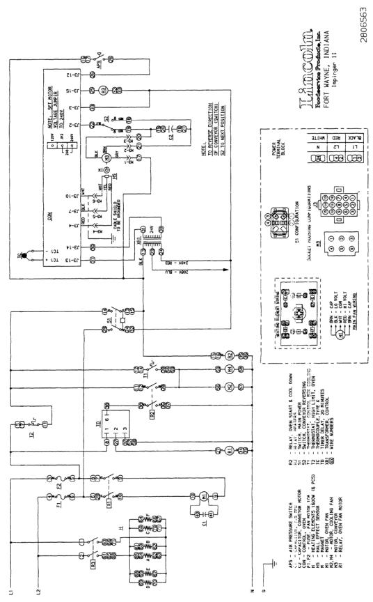
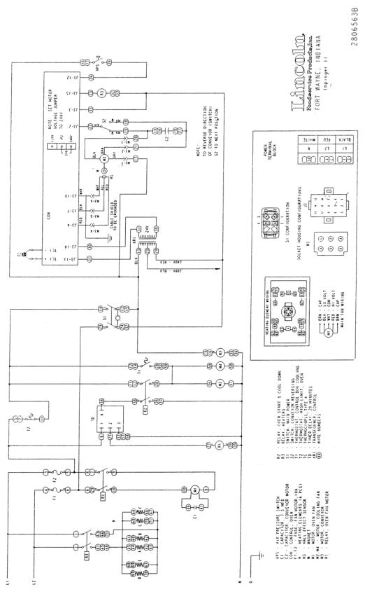
MODEL 1132-080-A, 1132-080-A1, 1133-080-A, 1133-080-A1
6 |
Impinger II – Advantage Digital Express Service Manual - Domestic |
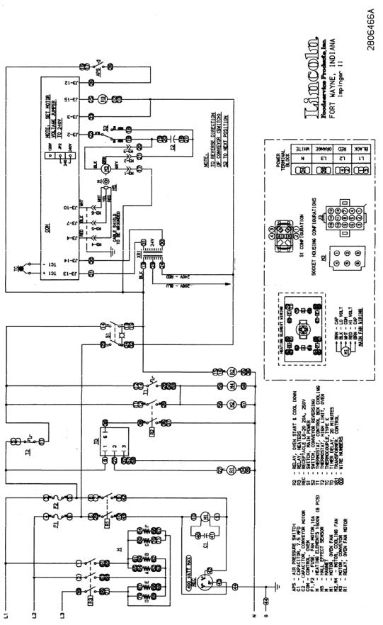
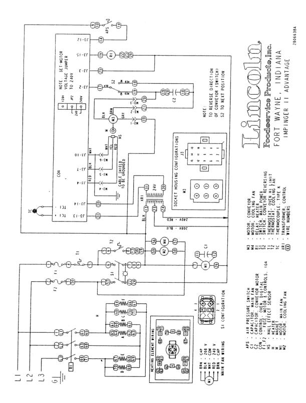
SCHEMATIC DIAGRAM MODEL 1161-080-A
Impinger II – Advantage Digital Express Service Manual - Domestic |
7 |
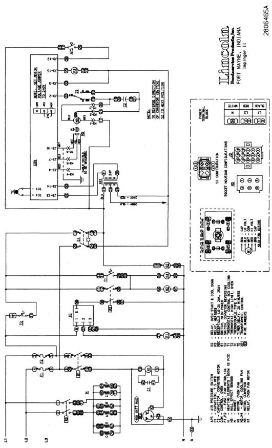
SCHEMATIC DIAGRAM MODEL 1162-080-A
8 |
Impinger II – Advantage Digital Express Service Manual - Domestic |
SCHEMATIC DIAGRAM
MODEL 1130-08H-A, 1131-08H-A
Impinger II – Advantage Digital Express Service Manual - Domestic |
9 |
SCHEMATIC DIAGRAM
MODEL 1132-08H-A, 1133-08H-A
10 |
Impinger II – Advantage Digital Express Service Manual - Domestic |
TROUBLESHOOTING GUIDE
GAS OVENS
MODEL 1116-080-A |
NAT. GAS |
120VAC |
60 HZ. |
||
MODEL 1116-080-A1 |
NAT. GAS |
120VAC |
60 HZ. |
||
MODEL 1117-080-A |
LP GAS |
120VAC |
60 HZ. |
||
MODEL 1117-080-A1 |
LP GAS |
120VAC |
60 HZ. |
||
|
|
|
|
|
|
SYMPTOM |
POSSIBLE CAUSE |
|
EVALUATION |
|
|
Oven fan will not run |
Incoming power supply |
|
Check circuit breakers, reset if required. Check |
||
|
|
|
power plug to be sure it is firmly in receptacle. |
||
|
|
|
Measure incoming power, call power co. if needed. |
||
|
Fuse, 10 Amp |
|
Check, replace if necessary. |
||
|
Fuse holder |
|
Check, replace if necessary. |
||
|
Hi-limit thermostat, |
|
Check for voltage on both sides of switch. Terminals |
||
|
control box |
|
are normally closed. If open, reset and test oven for |
||
|
|
|
proper operation. If thermostat will not hold, and |
||
|
|
|
control box temperature is not exceeding 140°F |
||
|
|
|
(60°C), replace thermostat. |
||
|
Switch, main power |
|
Check continuity between switch terminals. Replace |
||
|
|
|
switch as needed. |
|
|
|
Main fan motor |
|
Check for 120VAC at motor. If no voltage is present, |
||
|
|
|
trace wiring back to main power switch. |
||
|
|
|
WITH POWER OFF: Check for opens, shorts or |
||
|
|
|
grounds. Turn fan blade to check for locked rotor. |
||
|
Capacitor |
|
Check for shorts or grounds. |
||
|
|
|
WARNING: Capacitor has a stored charge, |
||
|
|
|
discharge before testing. |
||
No control box cooling |
Incoming power |
|
Check circuit breakers, reset if required. Check |
||
|
|
|
power plug to be sure it is firmly in receptacle. |
||
|
|
|
Measure incoming power, call power co. if needed. |
||
|
Switch, main power |
|
Check continuity between switch terminals. Replace |
||
|
|
|
switch as needed. |
|
|
|
Cooling fan |
|
Check for 120VAC at cooling fan. If no voltage is |
||
|
|
|
present, trace wiring back to power switch. If voltage |
||
|
|
|
is present, and motor does not run, check for opens, |
||
|
|
|
shorts or grounds. |
|
|
|
|
|
WITH POWER OFF: Check for locked rotor. |
||
No automatic control box |
Incoming power supply |
|
Check circuit breakers, reset if required. Check |
||
cooling |
|
|
power plug to be sure it is firmly in receptacle. |
||
|
|
|
Measure incoming power, call power co. if needed. |
||
|
Cooling fan thermostat |
|
Check the cooling fan thermostat. (Thermostat |
||
|
|
|
closes at 120°F and opens at 100°F). With the |
||
|
|
|
cooling fan thermostat pre-heated, check for |
||
|
|
|
continuity. If switch is open, replace cooling fan |
||
|
|
|
thermostat. |
|
|
|
Cooling fan |
|
Check for 120VAC at cooling fan. If no voltage is |
||
|
|
|
present, trace wiring back to cooling fan thermostat. |
||
|
|
|
If voltage is present, and motor does not run, check |
||
|
|
|
for opens, shorts or grounds. |
||
|
|
|
WITH POWER OFF: Check for locked rotor. |
||
Oven will not heat |
Gas supply |
|
Check for adequate gas supply to oven. |
||
|
Manual gas shut off valve. |
Check to see that the manual gas shut off valve is |
|||
|
|
|
open. Also check flexible gas line connection for any |
||
|
|
|
damage. |
|
|
|
Main fan |
|
If not operating, refer to “Oven fan will not run”. |
||
|
|
|
|||
|
Centrifugal switch of main fan |
Check for 120VAC at wire #5 (input to centrifugal |
|||
|
motor |
|
switch, located at 6-pin connector in raceway near |
||
Impinger II – Advantage Digital Express Service Manual - Domestic |
11 |
|
|
the main fan motor) to neutral. If no voltage is |
|
|
present, trace wiring back to the main power switch. |
|
|
If voltage is present, check for 120VAC at wire #22 |
|
|
(output of centrifugal switch) to neutral. If no voltage |
|
|
is present at #22, and the motor is running, replace |
|
|
the main fan motor. |
|
Hi-limit thermostat, |
Terminals are normally closed. If open, reset |
|
oven cavity |
thermostat and retest. If thermostat will not hold for |
|
|
maximum oven temperature, and oven is not |
|
|
exceeding temperature setting, check for proper |
|
|
location of capillary bulb in its spring holder. If the |
|
|
capillary checks okay, replace the hi-limit thermostat. |
|
Burner blower motor |
Check for 120VAC supplied to burner blower motor |
|
|
at wire #13 to neutral. If no voltage is present, trace |
|
|
wiring back to the main power switch. If voltage is |
|
|
present, and the motor is not running, check for |
|
|
opens, shorts or grounds. |
|
|
WITH POWER OFF: Turn motor to check for locked |
|
|
rotor. |
|
Burner transformer |
Check for 120VAC supplied to the primary of the |
|
|
burner transformer. If no voltage is present, trace |
|
|
wiring back to the oven cavity hi-limit thermostat. If |
|
|
voltage is present, check for 24VAC at transformer |
|
|
secondary. If there is primary voltage but no |
|
|
secondary voltage, replace burner transformer. |
|
Centrifugal switch of burner |
Check for 24VAC at motor connector, wire #13 to |
|
blower motor |
neutral. If voltage is not present, trace wiring back to |
|
|
transformer. If voltage is present, check for voltage at |
|
|
wire #14 to neutral. If no voltage is present at wire |
|
|
#14, and motor is running, replace burner blower |
|
|
motor. |
|
Ignition control |
Check for 24VAC at ignition control terminals marked |
|
|
“24V”, if no voltage is present, trace wiring back to |
|
|
centrifugal switch. Check for 120VAC to ignition |
|
|
control at terminal “L1” to neutral. If no voltage is |
|
|
present, trace wiring back to main power switch. |
|
|
When 24VAC is supplied to the ignition control, the |
|
|
ignition control switches 120VAC to the hot surface |
|
|
igniter If 24VAC and 120VAC are supplied to ignition |
|
|
control, but there is no voltage at the hot surface |
|
|
igniter, replace the ignition control. |
|
Hot surface igniter |
If 120VAC is present at hot surface igniter terminals, |
|
|
visually check to see that the igniter is heating |
|
|
(igniter may be viewed through the port in the end of |
|
|
burner tube). The igniter should glow bright red. If the |
|
|
igniter does not heat, replace the hot surface igniter. |
|
Ignition control |
After 45 seconds of hot surface igniter pre-heat, the |
|
|
ignition control will switch 24VAC to the gas control |
|
|
valves. Check for 24VAC output from ignition control |
|
|
across terminals marked “valve” and “valve gnd”. If |
|
|
no voltage is present, replace ignition control. |
|
Gas control valves |
When 24VAC is supplied to the gas control valves, |
|
|
the valve should open. Check for gas pressure at the |
|
|
manifold tap located just before the burner. If there is |
|
|
no pressure, check the incoming gas supply to be |
|
|
sure all manual valves are open and flexible gas |
|
|
hose is properly connected. If gas is present, and the |
|
|
gas control valve is energized, but there is no gas |
|
|
pressure at the burner manifold, replace the gas |
|
|
control valves. |
Flame will not stay lit |
Hot surface igniter |
Six seconds after the gas valve opens, ignition must |
12 |
Impinger II – Advantage Digital Express Service Manual - Domestic |
 Loading...