

Page 1

Write down the following information
for future reference:
Serial Number:
Date of Purchase:
Belt Drive Garage Door Opener
Model 8550
FOR RESIDENTIAL USE ONLY
■ Please read this manual and the enclosed safety materials carefully!
■ Fasten the manual near the garage door after installation.
■ The door WILL NOT CLOSE unless the Protector System® is connected and properly
aligned.
■ Periodic checks of the garage door opener are required to ensure safe operation.
■ The model number label is located on the left side panel of your garage door opener.
■ This garage door opener is ONLY compatible with MyQ™ and Security✚®2.0
accessories.
■ DO NOT enable the Timer-To-Close feature if you are installing the garage door
opener on a one-piece door. The Timer -To-Close is to be used ONLY with
sectional doors.
NOTE: If you are installing the garage door opener on a one-piece door, visit
www.liftmaster.com for installation instructions.
.
www.liftmaster.com
The Chamberlain Group, Inc.
Elmhurst, Illinois 60126-1196
845 Larch Avenue
Contents
BELT DRIVE GARAGE DOOR OPENER .. 1
PREPARATION ............................. 2
ASSEMBLY ................................. 4
INSTALLATION ........................ 6-13
INSTALL THE DOOR CONTROL .....14-16
INSTALL THE
PROTECTOR SYSTEM
POWER ................................21-22
ADJUSTMENT.........................23-25
BATTERY BACKUP ...................26-27
OPERATION ...............................28
FEATURES.................................29
DOOR CONTROL .....................30-31
REMOTE CONTROLS .................32-33
TO ERASE THE MEMORY ...............33
TO OPEN THE DOOR MANUALLY ......34
MAINTENANCE ...........................34
TROUBLESHOOTING .................35-36
REPAIR PARTS .......................37-38
ACCESSORIES ............................39
WARRANTY ...............................40
®
..............17-20
Page 2
Torsion Spring
Extension Spring
2
1
3/16
7/16
1/2
5/32
5/16
5/8
9/16
1/4
7/16
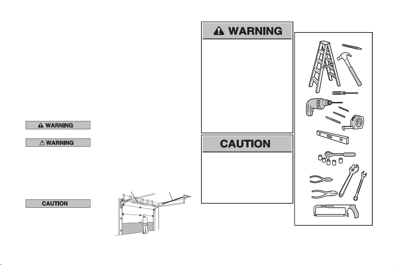
Preparation
Safety Symbol and Signal Word Review
This garage door opener has been designed and
tested to offer safe service provided it is installed,
operated, maintained and tested in strict
accordance with the instructionsand warnings
contained in this manual.
When you see these Safety Symbols and Signal
Words on the following pages, they will alert you
to the possibilityof serious injury ordeath if you
do not comply with the warnings that accompany
them.The hazard may come from something
mechanical or from electricshock. Read the
warnings carefully.
Mechanical
When you see this Signal Word on the following
pages, it will alert you to the possibilityof damage
to your garage door and/or the garage door
opener if you do not complywith the cautionary
statements that accompany it. Read them
carefully.
Electrical
Check the Door
1. Disable locks and remove any ropes
connected to the garage door.
2. Lift the door halfwayup. Release the
door. Ifbalanced, it should stay in
place, supported entirely by its springs.
3. Raise and lower the door to check for
binding or sticking. Ifyour door binds,
sticks, or is out of balance, call a trained
door systems technician.
4. Checkthe seal on the bottomof the
door. Any gap between the floor and
the bottom of the door must not exceed
1/4 inch (6 mm). Otherwise, the safety
reversal systemmay not work properly.
5. The opener should be installed above
the center of the door. Ifthere is a
torsion spring or center bearing plate
in the way of the header bracket,it may
be installed within 4 feet(1.2 m) to the
left or right of the door center.See
installing the Header Bracket section.
Tools Needed
To prevent possible SERIOUSINJURYor
DEATH:
• ALWAYS call a trained door systems
technician if garage door binds, sticks, or is
out of balance. An unbalanced garage
door may not reverse when required.
• NEVER try to loosen, move or adjust
garage door, door springs, cables, pulleys,
bracketsor their hardware, ALLof which
are under EXTREMEtension.
• Disable ALLlocks and remove ALLropes
connected to garage door BEFORE
installation and operating garage door
opener to avoid entanglement.
To prevent damage to garage door and
opener:
• ALWAYS disable locksBEFORE installing
and operating the opener.
• ONLY operate garage door opener at
120 V, 60 Hz to avoid malfunction and
damage.
2
Page 3

A
B
C
J
N
I
O
D
E
F
H
G
K
L
M
Overview/Carton Inventory
GARAGE DOOR OPENER ASSEMBLY
A. tekcarb redaeH
B. Pulley and bracket
C. tekcarb rooD
D. mra rood devruC
E. mra rood thgiartS
F. yellorT
G. Emergency release rope and handle
H. Rail
I. renepo rood egaraG
NOTE: Accessories will vary depending on the garage door opener model purchased. Depending on your specific model, other accessories
may be included with your garage door opener. The instructions for these accessories will be attached to the accessory and are not included
in this manual. The images throughout this manuals are for reference and your product may look different.
J. swercs dna revoc tekcorpS
K. tleB
L. lortnoc rooD
M. eriw etihw/der dna etihW
The Protector System
®
N. srosnes gnisrever ytefaS
with white and white/black wire attached:
Sending Sensor (1) Receiving Sensor (1)
and Safety Sensor Brackets (2)
O. erutaretil dna slebal ytefaS
Hardware
Assembly
H1 Hex Screw #8x3/8" (3)
[packed with the sprocket cover]
Installation
H2 Hex Bolt 5/16"-18 x 7/8" (4)
H3 Lag Screw 5/16"-9 x 1-5/8" (2)
H4 Lag Screw 5/16"-18 x 1-5/8" (2)
H5 Clevis Pin 5/16" x 2-3/4" (1)
H6 Clevis Pin 5/16" x 1-1/4" (1)
H7 Clevis Pin 5/16" x 1" (1)
H8 Nut 5/16"-18 (4)
H9 Lock Washer 5/16"-16 (4)
H10 Self-Threading Screw 1/4"-14 x 5/8" (2)
H11 Ring Fastener (3)
H12 Carriage Bolt 1/4"-20 x 1/2" (2)
H13 Wing Nut 1/4"-20 (2)
Door Control Hardware
H14 Screw 6AB x 1-1/4" (2)
H15 Screw 6-32 x 1" (2)
H16 Drywall Anchors (2)
H17 Insulated Staples (10)
895MAX
Remote Control
880LM
Smart Control
Panel
®
829LM
Garage Door
Monitor
MyQ™ AND SECURITY✚®2.0
ACCESSORIES
3
Page 4
Mounted in the
garage door opener
HARDWARE
H1 (3)
Hex Screw
#8x3/8"
(Packed with the
sprocket cover)
H1
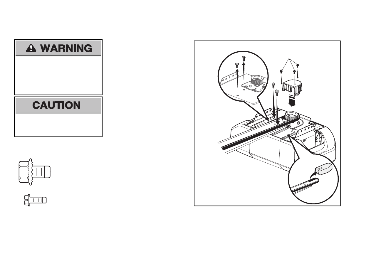
Assembly
1 Attach the rail to the garage door opener
NOTE: ONLY use the bolts removed from the
garage door opener. Place the garage door
To avoid possible SERIOUS INJURY to finger
from moving garage door opener:
• ALWAYS keep hand clear of sprocket while
operating opener.
• Securely attach sprocketcover BEFORE
operating.
To avoid SERIOUS damage to garage door
opener, use ONLY those bolts/fasteners
mounted in the top of the opener.
.
opener on the packing material to prevent
scratching.
1.1 Remove the two bolts from the top of the
garage door opener.
1.2 Align the rail and the styrofoam over the
sprocket. Cutthe tape from the rail, belt,
and styrofoam.
1.3 Fasten the rail with the previously removed
bolts.
1.4 Position the belt around the garage door
opener sprocket.
1.5 Attach the sprocketcover over the garage
door opener sprocket and attach with hex
screws(H1).
4
Page 5

2 Tighten the Belt
Spring Trolley Nut
(To motor unit)
Nut ring
slot
Nut Ring
Nut Ring
AFTER RELEASE
1-1/4"
(3.18 cm)
BEFORE
1"
(2.5 cm)
2.1 By hand, thread the spring trolley nut on the threaded shaft until it is finger tight against
2.2 Inserta flathead screwdriver tip into one of the nut ring slots and brace it firmly against the trolley.
the trolley. Do not use any tools.
2.3 Tighten the spring trolley nut with an adjustable wrench or a 7/16” open end wrench about a quarter turn until the spring releases and snaps the nut ring against the trolley. This sets the spring to
optimum belt tension.
5
Page 6

WARNING
Installation
IMPORTANT INSTALLATION INSTRUCTIONS
To reduce the risk of SEVERE INJURY or DEATH:
1. READ AND FOLLOW ALL INSTALLATION WARNINGS AND INSTRUCTIONS.
2. Install garage door opener only on properly balanced and lubricated garage door. An
improperly balanced door may not reverse when required and could result in SEVERE
INJURY or DEATH.
3. ALL repairs to cables, spring assemblies and other hardware MUST be made by a trained
door systems technician BEFORE installing opener.
4. Disable ALL locks and remove ALL ropes connected to garage door BEFORE installing
opener to avoid entanglement.
5. Install garage door opener 7 feet (2.13 m) or more above floor.
6. Mount the emergency release within reach, but at least6 feet (1.83 m) above the floor and
avoiding contactwith vehicles to avoid accidental release.
7. NEVER connectgarage door opener to power source until instructed to do so
8. NEVERwear watches,rings or loose clothing while installing or servicing opener. They could
be caught in garage door or opener mechanisms.
NOTE:If you are installing the garage door opener on a one-piece door, visit www.liftmaster.com for installation instructions.
9. Install wall-mounted garage door control:
• within sight of the garage door.
• out of reach of children at minimum height of 5 feet(1.5 m).
• away fromALL moving parts of the door.
10. Place entrapment warning label on wall next to garage door control
11. Place manual release/safety reverse test label in plain view on inside of garage door.
12. Upon completion of installation, test safetyreversal system. Door MUST reverse on.contactwith
a 1-1/2" (3.8 cm) high object(or a 2x4 laid fl at) on the floor.
13. To avoid SERIOUS PERSONAL INJURY or DEATHfrom electrocution, disconnectALL
electric and battery power BEFORE performing any service or maintenance.
14. DO NOT enable the Timer-to-Close functionality if operating either one-piece or swinging
garage doors. To be enabled ONLY when operating a sectional door.
6
Page 7
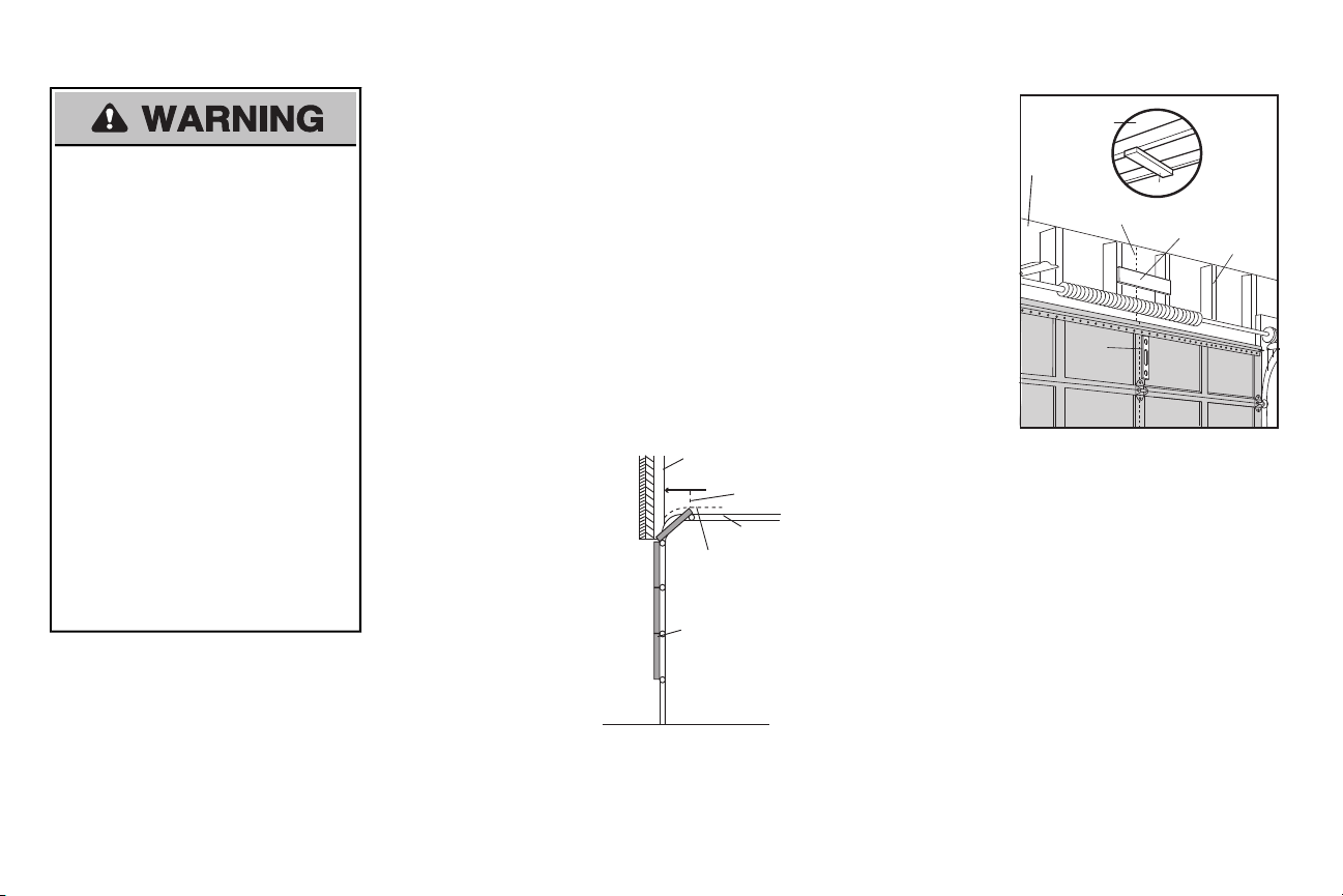
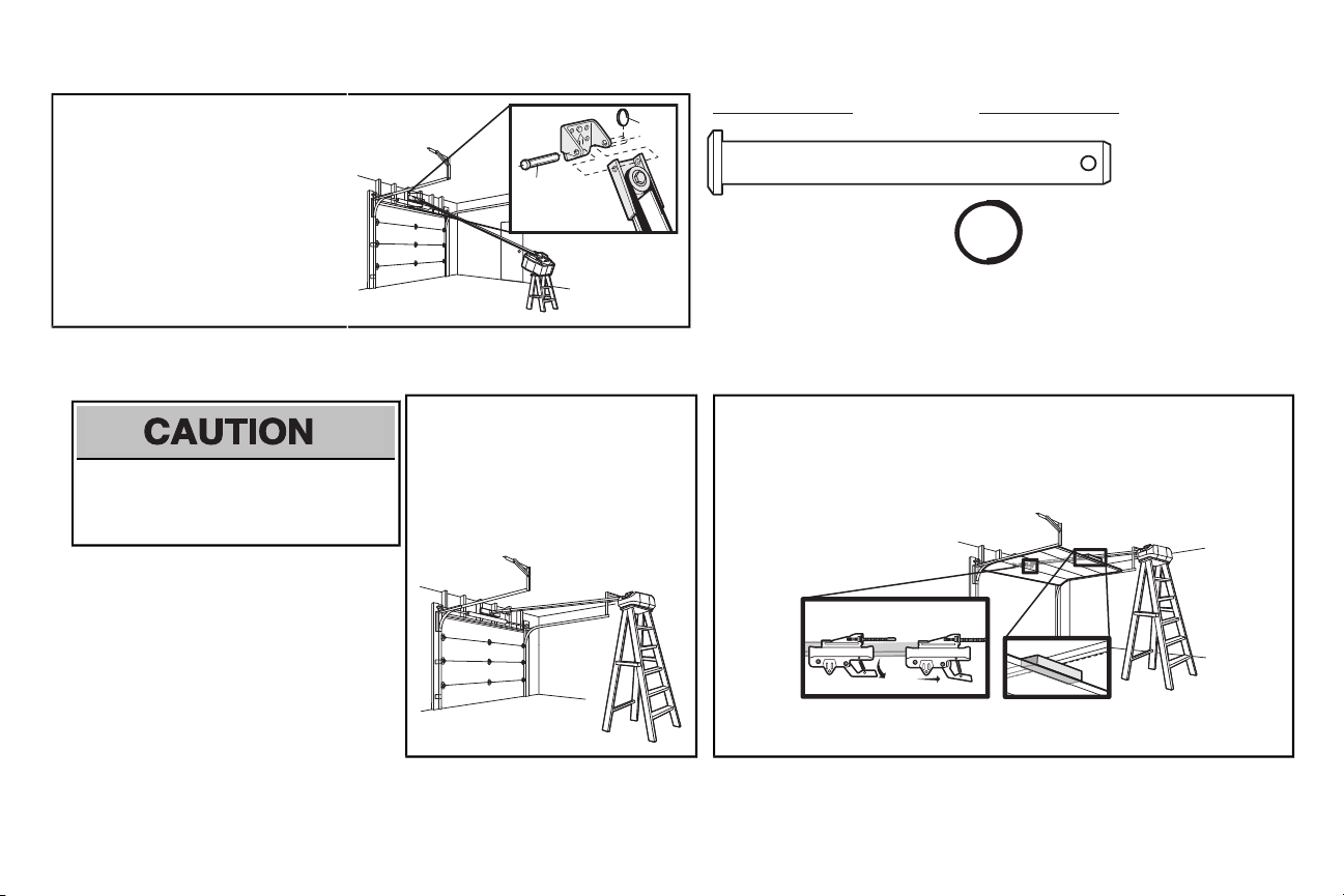
1 Determine the header bracket location
Sectional door with curved track
Header Wall
Track
2" (5 cm)
Highest Point
of Travel
Door
Header Wall
Unfinished Ceiling
Vertical Centerline
of Garage Door
2x4
2x4
Structural
Supports
Level
(Optional)
OPTIONAL
CEILING
MOUNT FOR
HEADER
BRACKET
To prevent possible SERIOUS INJURY or
DEATH:
• Header bracketMUST be RIGIDLY
fastened to structural support on header
wall or ceiling, otherwise garage door might
NOT reverse when required. DO NOT
install header bracketover drywall.
• Concrete anchors MUSTbe used if
mounting header bracket or 2x4 into
masonry.
• NEVER try to loosen, move or adjust
garage door, springs, cables, pulleys,
brackets, or their hardware, ALL of which
are under EXTREME tension.
• ALWAYS call a trained door systems
technician if garage door binds, sticks, or is
out of balance. An unbalanced garage
door might NOT reverse when required.
• DO NOT enable the Timer-to-Close
functionality if operating either one-piece or
swinging garage doors. To be enabled
ONLY when operating a sectional door.
NOTE: If you are installing the garage door opener on a one-piece door, visit www.liftmaster.com for
installation instructions.
1.1 Close the door and mark the inside vertical centerline of the garage door.
1.2 Extend the line onto the header wall above the door.
You can fasten the header bracket within4 feet (1.22 m) of the left or right of the door
center only if a torsion springor center bearing plate is inthe way; oryoucan attach it to
the ceiling when clearance is minimal.(It may be mountedonthe wallupside down if
necessary, to gainapproximately 1/2" (1 cm).
Ifyou need to install the header bracketon a 2x4 (on wall or ceiling), use lag screws(not
provided) to securely fasten the 2x4 to structural supports.
1.3 Open your door to the highest point of travel as shown.Draw an intersecting horizontal line on
the header wall 2" (5 cm) above the high point. This height will provide travel clearance for the
top edge of the door.
NOTE: If the total number of inches exceeds the height available in your garage, use the maximum
height possible, or refer to page 8 ceiling installation.
7
Page 8
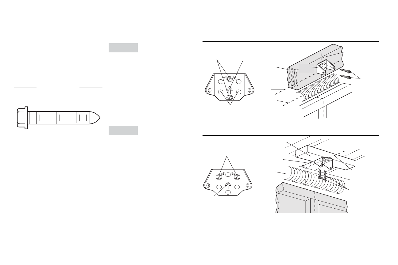
HARDWARE
H3 (2)
Lag Screw
5/16"-9x1-5/8"
UP
CEILING MOUNT ONLY
Wall Mount
Optional
Mounting
Holes
H3
Vertical
Centerline of
Garage Door
(Header Wall)
Header
Bracket
2x4 Structural
Support
Door Spring
(Garage Door)
Highest Point of
Garage Door
Travel
Horizontal
Line
The nail hole is for positioning
swercs gal esu tsum uoY .ylno
.tekcarb redaeh eht tnuom ot
UP
CEILING MOUNT ONLY
(Header Wall)
Ceiling Mounting Holes
(Finished Ceiling)
Vertical
Centerline of
Garage Door
Header
Bracket
6" (15 cm)
Maximum
Door Spring
(Garage Door)
H3
The nail hole is for positioning
swercs gal esu tsum uoY .ylno
.tekcarb redaeh eht tnuom ot
Installation
2 Install the Header Bracket
You can attach the header bracket either to the
wall above the garage door, or to the ceiling.
Follow the instructions which will work best for
your particular requirements.Donot installthe
header bracket overdrywall. If installing into
masonry,use concrete anchors (not provided).
OPTION A WALL INSTALLATION
2.1A Center the bracket on the vertical
centerline with the bottomedge of the
bracket on the horizontal line as shown
(with the arrow pointing toward the
ceiling).
2.2A Mark the vertical set of bracket holes (do
not use the holes designated for ceiling
mount). Drill 3/16" pilot holes and fasten
the bracketsecurelyto a structural
support with the hardware provided (H3).
OPTION B CEILING INSTALLATION
2.1B Extend the vertical centerline onto the
ceiling as shown.
2.2B Center the bracket on the vertical mark,
no more than 6" (15 cm) from the wall.
Make sure the arrow is pointing away
from the wall. The bracketcan be
mounted flush against the ceiling when
clearance is minimal.
2.3B Mark the side holes. Drill 3/16" pilot holes
and fasten bracket securely to a structural
support with the hardware provided (H3).
8
Page 9
H11
H5
HARDWARE
H5
Clevis Pin
5/16"x2-3/4"
H11
Ring Fastener
Connected Disconnected
3 Attach the rail to the header bracket
3.1 Align the rail with the header bracket.
Insertthe clevis pin (H5) through the
holes in the header bracketand rail.
Secure with the ring fastener (H11).
NOTE: Use the packing material as a
protective base for the garage door opener.
4 Position the garage door opener
To prevent damage to garage door, restgarage
door opener rail on 2x4 placed on top section of
door.
4.1 Remove the packing material and lift the
garage door opener onto a ladder.
NOTE: A 2x4 is ideal for setting the distance
between the rail and the door. If the ladder is
not tall enough you will need help at this point.
9
4.2 Fully open the door and place a 2x4 (laid flat) under the rail.
NOTE: If the door hits the trolley when it is raised, pull the trolley release arm down to
disconnectthe inner and outer trolley. Slide the outer trolley toward the garage door opener.
The trolley can remain disconnected until instructed.
Page 10
HARDWARE
H4 (2)
Lag Screw 5/16"- 18x1-5/8"
H2 (2)
Hex Bolt 5/16"- 18x7/8"
H8 (2)
Nut 5/16"-18
H9 (2)
Lock Washer
5/16"-16
Finished Ceiling
Unfinished Ceiling
Finished
Ceiling
H4
(not provided)
H4
(not provided)
H2
H8
H9
Installation
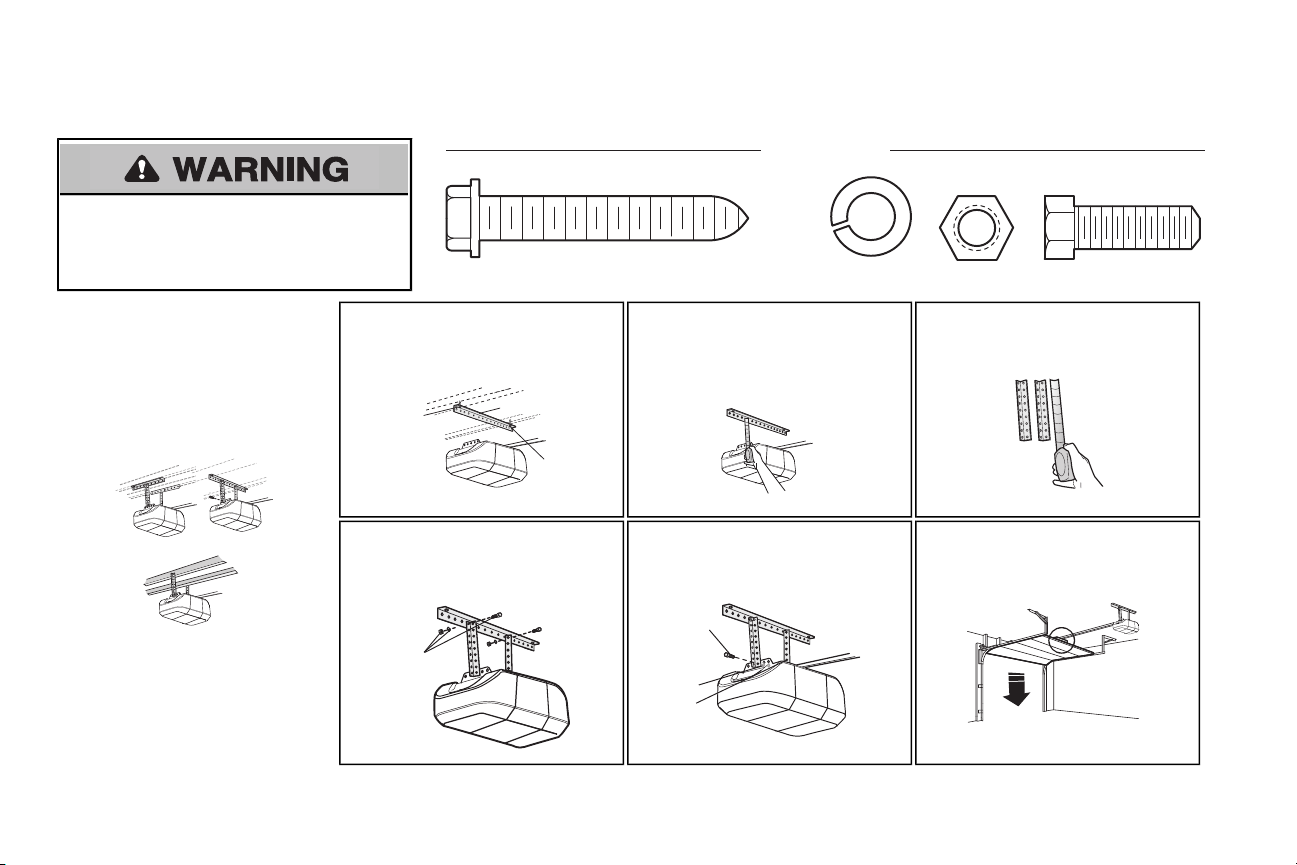
5 Hang the garage door opener
To avoid possible SERIOUS INJURY from a
falling garage door opener, fasten it SECURELY to
structural supports of the garage. Concrete anchors MUST
be used if installing ANY brackets into masonry.
Hanging the garage door opener will vary
depending on your garage. Below are three
example installations.Your installation may be
different.For ALL installations the garage door
opener MUST be connected to structural
supports.The instructions illustrate one of the
examples below.
5.1 On finished ceilings,use the lag screws
(H3) to attach a support bracket(not
provided) to the structural supports
before installing the garage door opener.
5.4 Attach the end of each hanging bracketto
the support bracket with appropriate
hardware (not provided).
5.2 Make sure the garage door opener is
aligned with the header bracket. Measure
the distance from each side of the garage
door opener to the support bracket.
5.5 Attach the garage door opener to the
hanging brackets with the bolts (H2), lock
washers (H9) and nuts (H8).
10
5.3 Cut both pieces of the hanging bracket to
required lengths.
5.6 Remove the 2x4 and manually close the
door. Ifthe door hits the rail, raise the
header bracket.
Page 11
or or
Trolley
Release Arm
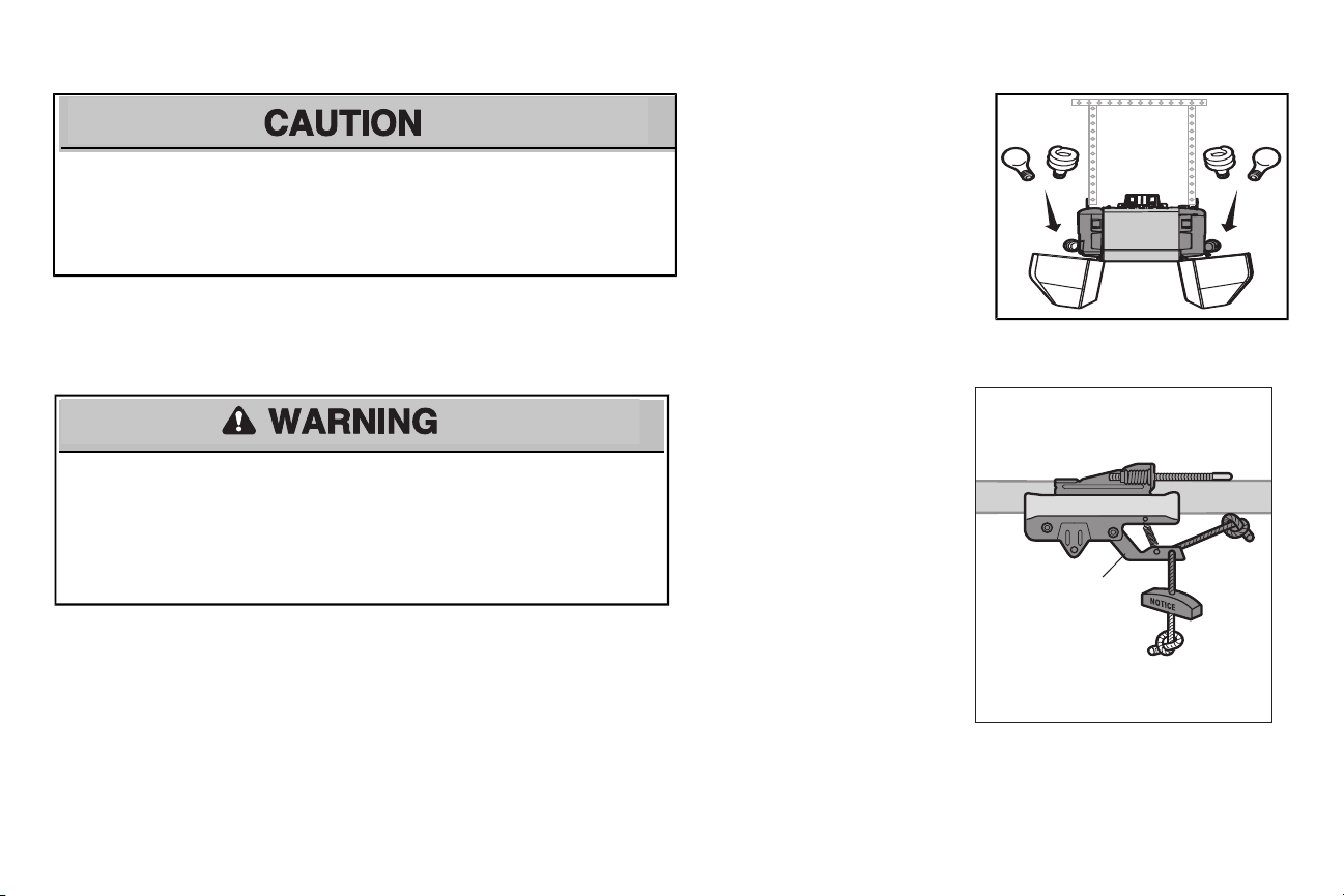
6 Install the light bulbs
To prevent possible OVERHEATING of the end panel or light socket:
• Use ONLY A19 incandescent or compactfluorescent light bulbs.
• DO NOT use incandescentbulbs larger than 100W.
• DO NOT use compact fluorescent light bulbs larger than 26W (100W) equivalent.
• DO NOT use halogen bulbs.
• DO NOT use short neck or specialtylight bulbs.
7 Attach the emergency release rope and handle
To prevent possible SERIOUS INJURY or DEATHfrom a falling garage door:
• Ifpossible, use emergency release handle to disengage trolley ONLY when garage door is
CLOSED. Weak or broken springs or unbalanced door could resultin an open door falling
rapidly and/or unexpectedly.
• NEVER use emergency release handle unless garage doorway is clear of persons and
obstructions.
• NEVER use handle to pull door open or closed. If rope knot becomesuntied, you could fall.
6.1 Pull on the top center of the light lens and
rotate the light lens down.
6.2 Insertan A19 incandescent or compact
fluorescentlight bulb (100 wattmaximum),
into the light socket.
6.3 Rotate the lens up to close.
NOTE: The use of short neckor specialitylight
bulbs mayoverheat the end panel or light socket.
7.1 Insertone end of the emergency release
rope through the handle. Make sure that
“NOTICE” is right side up. Tie a knot at
least 1 inch (2.5 cm) from the end of the
emergency release rope.
7.2 Insertthe other end of the emergency
release rope through the hole in the
trolley release arm. Make sure the
handle is 6 feet (1.83 m) above the floor
and secure with a knot.
NOTE: If it is necessary to cut the emergencyrelease rope, seal the cutend with a match or lighter to prevent unraveling. Ensure the emergency release
rope and handle are above the top of all vehicles to avoid entanglement.
11
Page 12
H10 (2)
Self-Threading Screw
1/4˝-14x5/8˝
HARDWARE
Door
Bracket
Vertical
Centerline
of Garage Door
UP
Vertical
Reinforcement
FIGURE 2
H10
UP
H10
Vertical
Centerline
of Garage
Door
FIGURE 4
FIGURE 1
Door
Bracket
Nut
5/16"-18
Bolt
5/16"-18x2"
(Not Provided)
Lock Washer
5/16"
UP
Vertical Reinforcement
FIGURE 3
Vertical
Centerline
of Garage Door
UP
Inside Edge
of Door or
Reinforcement Board
Bolt 5/16"x2"
(Not Provided)
FIGURE 5
Vertical
Centerline
of Garage
Door
Installation
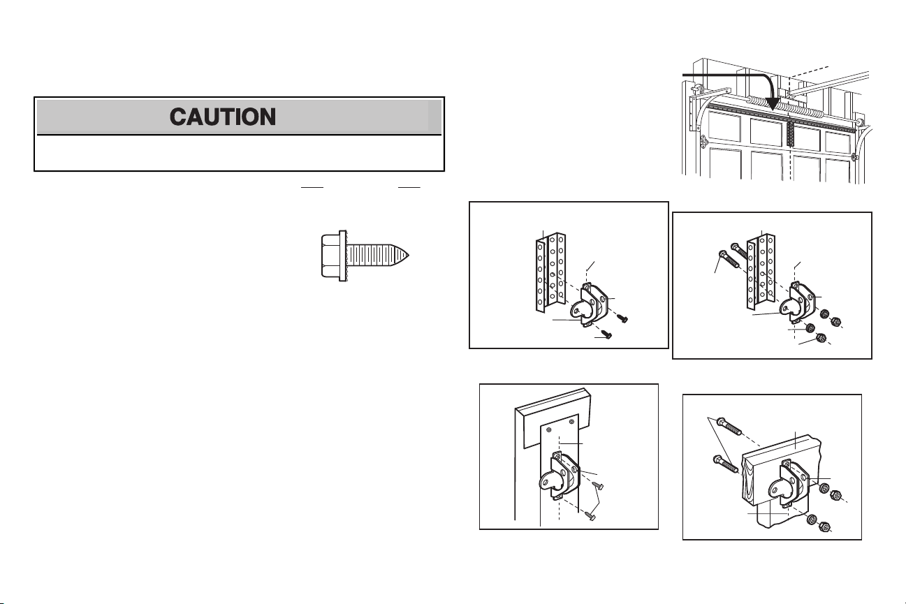
8 Install the door bracket
Fiberglass,aluminum or lightweight steel garage doors WILLREQUIRE reinforcementBEFORE
installation of door bracket.Contact your door manufacturer for reinforcement kit.
Figure 1 shows one piece of angle iron as the horizontal
brace. For the vertical brace, 2 pieces of angle iron are
used to create a U-shaped support. The best solution is to
checkwith your garage door manufacturer for an opener
installation door reinforcementkit.
NOTE: Many door reinforcement kitsprovide for direct
attachment of the clevispin and door arm. In thiscase you
will not need the door bracket;proceed to the next step.
8.1 Center the door bracket on the previously marked vertical centerline used for the header bracket
installation.Note correct UP placement, as stamped inside the bracket.
8.2 Position the top edge of the bracket 2"-4" (5-10 cm) below the top edge of the door, OR directlybelow
any structural support across the top of the door.
8.3 Mark,drill holes and install as follows, depending on your door’s construction:
Metal or light weight doors usinga vertical angle ironbrace between the doorpanelsupport and
the door bracket:
• Drill 3/16" fastening holes. Secure the door bracketusing the two self threading screws(H10).
(Figure 2)
• Alternately,use two 5/16" bolts, lock washers and nuts (not provided). (Figure 3)
Metal,insulated orlight weightfactory reinforced doors:
• Drill 3/16" fastening holes. Secure the door bracketusing the self-threading screws(H10).
(Figure 4)
NOTE: The 1/4"-14x5/8" self-threading screwsare not intended for use on wood doors.
Wood Doors:
• Use top and bottomor side to side door bracketholes. Drill 5/16” holes through the door and
secure bracketwith 5/16"x2" carriage bolts, lock washers and nuts(not provided). (Figure 5)
A horizontal and vertical reinforcement is
needed for lightweight garage doors
(fiberglass, aluminum, steel, doors with glass
panel,etc.) (not provided).
A horizontal reinforcement brace should be
long enough to be securedto two or three
vertical supports. A vertical reinforcement
brace shouldcover the height of the top panel.
12
Page 13

Straight
Door Arm
Curved
Door
Arm
(Groove
facing out)
CORRECT
INCORRECT
Straight
Door
Arm
Curved
Door
Arm
H11
H7
H11
H6
HARDWARE
H2 (2)
Hex Bolt 5/16"-18x7/8"
H8 (2)
Nut
5/16"-18
H9 (2)
Lock
Washer
5/16" -16
H7
Clevis Pin
5/16"x1"
H6
Clevis Pin 5/16"x1-1/4"
H11 (2)
Ring Fastener
H8
H9
H2
H8
H9
H2
If the straight door arm is hanging
down too far, you may cut 6 inches
(15 cm) from the solid end.
Trolley
release arm
9 Connect the door arm to the trolley
IMPORTANT: The groove on the straight door arm MUST face away from the curved door arm.
9.1 Close the door. Disconnectthe trolley by
pulling the emergency release handle.
Slide the outer trolley back (away from
the door) about 2" (5 cm).
9.4 Align the straight door arm with the
curved door arm.Select two aligned
holes (as far apart as possible) and
attach using the bolts (H2), nuts(H8)
and lock washers (H9).
9.2 Attach the straight door arm to the outer
trolley using the clevispin (H7).Attach
with the ring fastener (H11).
NOTE: If the holes do not line up, reverse the
straight door arm. Selecttwo aligned holes (as
far apart as possible) and attach using the bolts
(H2), nuts (H8) and lock washers (H9).
.
13
9.3 Attach the curved door arm to the door
bracket using the clevis pin (H6).
Attach with the ring fastener (H11).
9.5 Pull the emergency release handle
toward the garage door opener until the
trolley release arm is horizontal. The
trolley will re-engage automatically when
the garage door opener is activated.
Page 14
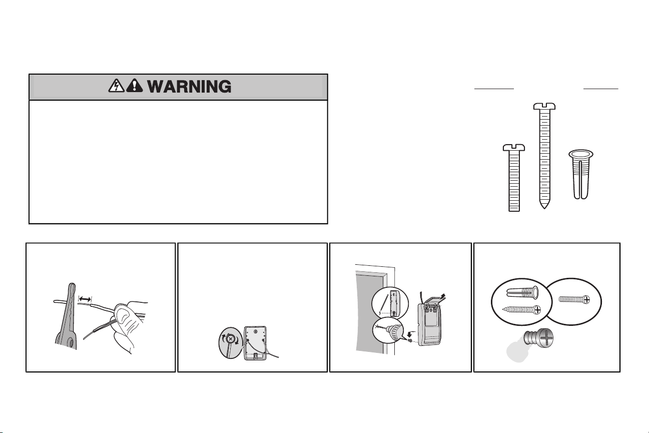
Install the Door Control
H14 (2)
Screw
6ABx1-1/4"
HARDWARE
H16 (2)
Drywall
Anchors
H15 (2)
Screw
6-32x1"
7/16"
(11 mm)
Wall
H15
DRYWALL
GANG BOX
H14
H16
1 Install the door control
INTRODUCTION
Compatible with MyQ™ and Security+®2.0
To prevent possible SERIOUS INJURY or DEATHfrom electrocution:
• Be sure power is NOT connected BEFORE installing door control.
• Connect ONLY to 24 VOLT low voltage wires.
To prevent possible SERIOUS INJURY or DEATHfrom a closing garage door:
• Install door control within sight of garage door, out of reach of children at a minimum height of 5 feet
(1.5 m), and away from ALL moving parts of door.
• NEVER permit children to operate or play with door control push buttons or remote control
transmitters.
• Activate door ONLY when it can be seen clearly, is properly adjusted, and there are no
obstructions to door travel.
• ALWAYS keep garage door in sight until completelyclosed. NEVER permit anyone to cross path of
closing garage door.
NOTE: For gang box installations it is not necessary to drill holes or install the drywall anchors.Use the existing holes in the gang box.
1.1 Strip 7/16 inch (11 mm) of insulation from
one end of the wire and separate the wires.
1.2 Connect one wire to each of the two screws
on the back of the door control.The wires
can be connected to either screw.
PRE-WIREDINSTALLATIONS:Choose
any two wires to connect, note which wires
are used so the correctwires are connected
at the garage door opener in a later step.
accessories. NOTE:Older LiftMaster
accessories and third partyproducts are not
compatible.Your garage door opener is
compatible with up to 2 Smart Control Panels or
4 of any other Security+®2.0 door controls.
Install the door control within sight of the door at
a minimumheight of 5 feet (1.5 m) where small
children cannot reach,and away from the
moving partsof the door.
NOTE: Your product may look different than
moving partsof the door the illustrations.
1.3 Mark the location of the bottom mounting
14
hole and drill a 5/32 inch (4 mm) hole.
1.4 Install the bottomscrew, allowing 1/8 inch
(3 mm) to protrude fromthe wall.
Page 15

Install the Door Control
DRYWALL
H14
H16
H15
GANG BOX
HARDWARE
H17 (10)
Insulated Staple
H17
7/16"
(11 mm)
RED
WHITE
WHITE
GREY
k
1.5 Position the bottom hole of the door
1.6 Lift the push bar up and mark the top hole. 1.7 Remove the door control from the wall
control over the screw and slide
down into place.
2 Wire the door control to the garage door opener
2.1
Run the white and red/white wire from the door control to
the garage door opener. Attach the wire to the wall and
ceiling with the staples (H17) (not applicable for gang box
or pre-wired installations).Do not pierce the wire with the
staple as this may cause a short or an open circuit.
PRE-WIRED INSTALLATIONS: When wiring
the door control to the garage door opener
make sure you use the same wires thatare
connected to the door control.
and drill a 5/32 inch (4 mm) hole for
the top screw.
2.2
Strip 7/16 inch (11 mm) of insulation
from the end of the wire near the
garage door opener.
15
door control over the screw and
slide down into place. Attach the
top screw.
2.3
Connect the wire to the red and
white terminals on the garage
door opener. To insertor
release wires from the terminal,
push in the tab with screwdriver
tip.
1.8 Position the bottom hole of the
Page 16

Install the Door Control
3 Attach the warning labels
3.1 Attach the entrapment warning label on the wall near the door control with tacksor
staples.
3.2 Attach the manual release/safety reverse testlabel in a visible location on the inside of
the garage door.
16
Page 17

Install the Protector System
Invisible Light Beam
Protection Area
Safety Reversing Sensor
6" (15 cm) max. above floor
Safety Reversing Sensor
6" (15 cm) max. above floor
®
Introduction
Be sure power is NOT connected to the garage
door opener BEFORE installing the safety
reversing sensor.
To prevent SERIOUS INJURY or DEATH from
closing garage door:
• Correctlyconnectand align the safety
reversing sensor.This required safety
device MUST NOT be disabled.
• Install the safety reversing sensor so beam
is NO HIGHERthan 6" (15 cm) above
garage floor.
IMPORTANTINFORMATIONABOUTTHESAFETYREVERSINGSENSORS
The safety reversing sensors must be connected and aligned correctly before the garage dooropener will move in the down direction.
The sending sensor (with an amber LED) transmits an invisible light beam to the receiving sensor (with a green LED). If an obstruction breaks the light
beam while the door is closing, the door will stop and reverse to the full open position,and the garage door opener lightswill flash 10 times.
NOTE: For energy efficiency the garage door opener will enter sleep mode when the door is fully closed. The sleep mode shuts the garage door
opener down until activated. The sleep mode is sequenced with the garage door opener light bulb; as the light bulb turns off the sensor LEDswill turn
off and whenever the garage door opener lights turn on the sensor LEDs will light. The garage door opener will not go into the sleep mode until the
garage door opener has completed 5 cycles upon power up.
When installing the safety reversing sensors checkthe following:
• Sensorsare installed inside the garage, one on either side of the door.
• Sensorsare facing each other with the lenses aligned and the receiving sensor lens does not receive direct sunlight.
• Sensorsare no more than 6 inches (15 cm) above the floor and the light beam is unobstructed.
17
Page 18

Install the Protector System
HARDWARE
H12 (2)
Carriage Bolt
1/4"-20x1/2"
H13 (2)
Wing Nut
1/4"-20
H12
H13
(not provided)
In
side
G
a
rage
Wal
l
(not provided)
H12
Lens
H13
®
1 Install the Safety Reversing Sensors
The safety reversing sensors can be attached to the door track,the wall, or the floor. If the door track will not support the sensor bracket a wall installation is recommended. Choose one of the following installations.
OPTION A
1.1A Slide the curved arms of the sensor
OPTION B WALLINSTALLATION
Ifadditional clearance is needed an extension bracket(not provided) or wood blocks can be used. Make sure each bracket has the same amount of clearance so they will align correctly.
1.1B Position the sensor bracket againstthe
wall with the curved arms facing the
door. Make sure there is enough
clearance for the beam to be
unobstructed.Mark holes.
1.2B Drill 3/16 inch pilot holes for each
DOOR TRACK INSTALLATION
bracket around the edge of the door
track. Snap into place so that the
sensor bracketis flush againstthe
track.
sensor bracketand attach the sensor
bracketsto the wall using lag screws
(not provided).
1.2A Slide the carriage bolt (H12) into the
slot on each sensor.
1.3B Slide the carriage bolt (H12) into the
slot on each sensor.
1.3A Insert the bolt through the hole in the sensor
bracket and attach with the wing nut (H13). The
lenses on both sensors should point toward
each other. Make sure the lens is not obstructed
by the sensor bracket.
1.4B
Insertthe bolt through the hole in the sensor
bracket and attach with the wing nut (H13). The
lenses on both sensors should point toward
each other. Make sure the lens is not
obstructed by the sensor bracket.
18
Page 19

Install the Protector System
Insi
d
e
Garage
Wa
l
l
(not provided)
H12
H13
HARDWARE
H17 (10)
Insulated Staple
H17
7/16"
(11 mm)
RED
WHITE
WHITE
GREY
1 Install the Safety Reversing Sensors
®
OPTION C
FLOOR INSTALLATION
Use an extension bracket(not provided) or wood black to raise the sensor bracket if needed.
1.1C Carefully measure the position of both
sensor brackets so they will be the same
distance from the wall and unobstructed.
1.2C
Attach the sensor brackets to the floor
using concrete anchors (not
provided).
2 Wire the Safety Reversing
Sensors
PRE-WIRED INSTALLATIONS: If your garage
already has wires installed for the safety
reversing sensors, refer to the instructions on the
following page.
OPTION A
2.1A Run the wire from both sensors to the
INSTALLATION WITHOUT PRE-WIRING
garage door opener. Attach the wire to
the wall and ceiling with the staples
(H17).
1.3C
Slide the carriage bolt (H12) into the
slot on each sensor.
2.2A Strip 7/16 inch (11 mm) of insulation
from each set of wires. Separate the
wires.Twist the white wires together.
Twist the white/black wires together.
19
1.4C
Insertthe bolt through the hole in the sensor
bracket and attach with the wing nut (H13). The
lens on both sensors should point toward each
other. Make sure the lens is not obstructed by
the sensor bracket.
2.3A Insert the white wires into the white terminal on
the garage door opener. Insertthe white/black
wires into the grey terminal on the garage door
opener. To insert or remove the wires from the
terminal, push in the tab with a screwdriver tip.
Page 20

Install the Protector System
7/16"
(11 mm)
7/16"
(11 mm)
Safety reversing sensor wires
Pre-installed
wires
White
White/Black
Yellow
(for example)
Purple
(for example)
Not Provided
Pre-installed
wires
Safety reversing sensor wires
7/16"
(11 mm)
Yellow
Purple
RED
WHITE
WHITE
GREY
Purple
(for example)
Yellow
(for example)
To insert or remove the wires
from the terminal, push in the
tab with a screwdriver tip.
OPTION B PRE-WIRED INSTALLATION
®
2.1B Cut the end of the safety
reversing sensor wire, making
sure there is enough wire to
reach the pre-installed wires
2.2B Separate the safetyreversing sensor wires and strip 7/16 inch (11 mm) of
insulation fromeach end. Choose two of the pre-installed wires and strip 7/16
inch (11 mm)of insulation from each end. Make sure that you choose the
same color pre-installed wires for each sensor.
from the wall.
2.4B At the garage door opener, strip 7/16 inch (11 mm)of insulation from each end of the wires previously chosen for the
safety reversing sensors. Twistthe like-colored wirestogether.
20
2.3B Connectthe pre-installed wires to the sensor wires with wire nuts
making sure the colors correspond for each sensor. For example,
the white wire would connect to the yellow wire and the white/black
wire would connect to the purple wire.
2.5B Insert the wires connected to the white safetysensor wires to the
white terminal on the garage door opener. Insertthe wires thatare
connected to the white/black safetysensor wires to the grey
terminal on the garage door opener.
Page 21

Ground Tab
Green Ground
Screw
Ground Wire
Black
Wire
White Wire
PERMANENT WIRING CONNECTION
Wire Nuts
Power
1 Connect Power
To prevent possible SERIOUS INJURY or
DEATH from electrocution or fire:
• Be sure power is NOT connected to the
opener, and disconnectpower to circuit
BEFORE removing cover to establish
permanent wiring connection.
• Garage door installation and wiring MUST
be in compliance with ALL local electrical
and building codes.
• NEVER use an extension cord, 2-wire
adapter, or change plug in any way to make
it fit outlet. Be sure the opener is grounded.
To avoid installation difficulties, do not activate the garage door openerat this time.
To reduce the risk of electricshock, your garage door opener has a grounding type plug with a third
grounding pin. This plug will only fit into a grounding type outlet.If the plug doesn’t fitinto your outlet,
contacta qualified electrician to install the proper outlet.
THERE ARE TWO OPTIONS FOR CONNECTIONPOWER:
OPTION A
TYPICAL WIRING
1.1A Plug in the garage door opener into a grounded outlet.
1.2A DO NOTrun garage door opener at this time.
OPTION B
Ifpermanent wiring is required by your local code, refer to the following procedure.
To make a permanent connection through the 7/8" hole in the top of the motor unit (according to local
code):
PERMANENT WIRING
1.1B Be sure power is NOT connected to the opener, and disconnectpower to circuit.
1.2B Remove the garage door opener cover and set aside.
1.3B Remove the attached green ground terminal.
1.4B Cut black and white wires and strip away 1/2" (1 cm) of insulation, 3" (7.5 cm) before spade
terminals.
1.5B Remove the power cord from opener.
1.6B Install a conduit or flex cable adapter to the 7/8" hole.
1.7B Run wiresthrough conduit, cut to proper length and strip insulation.
1.8B Attach with wire nuts provided. Attachthe ground wire to the green ground screw.The opener
mustbe grounded.
1.9B Properly secure wire under plasticties so that wire does not come in contact withmoving parts.
1.10B Reinstall the cover.DO NOT run garage door opener at this time.
21
Page 22

Green LED
ROSNES GNIVIECERROSNES GNIDNES
Amber LED
If the receiving sensor is in
direct sunlight, switch it with
sending sensor so it is on the
opposite side of the door.
(invisible light beam)
Make sure there is
power to the garage
door opener.
Make sure the
sensor wire is not
shorted/broken.
RED
WHITE
WHITE
GREY
Make sure the sensor has been wired
correctly: white wires to white terminal
and white/black wires to grey terminal.
Make sure the sensors are aligned.Make sure the sensor wire is
not shorted/broken.
Power
2 Ensure the Safety Reversing Sensors are aligned
The doorwillnot close if the sensors have not been
installed andaligned correctly.
When the light beam is obstructed or misaligned while
the door is closing, the door will reverse and the
garage door opener lights will flash ten times. Ifthe
door is already open, it will not close. The sensorscan
be aligned by loosening the wing nuts,aligning the
sensors,and tightening the wing nuts.
.
IFTHE AMBER LED ON THE SENDING SENSOR IS NOT GLOWING: IFTHE GREEN LED ON THE RECEIVING SENSOR IS NOT GLOWING:
2.1 Check to make sure the LEDs in both sensors are glowing steadily. The LEDs in both sensors will glow steadily if they are aligned and
wired correctly.
3 Ensure the Door Control is wired correctly
Ifthe door control has been installed and wired correctly a message will display on the screen.
22
Page 23

UP (Open)
DOWN (Close)
UP Button
Adjustment
Button
DOWN Button
PROGRAMMING BUTTONS
Adjustments
Without a properly installed safety reversal
system, persons (particularly small children)
could be SERIOUSLY INJURED or KILLED by a
closing garage door.
• Incorrectadjustmentof garage door travel
limitswill interfere with proper operation of
safety reversal system.
• After ANY adjustmentsare made, the safety
reversal systemMUSTbe tested. Door
MUSTreverse on contact with 1-1/2" (3.8
cm) high object (or 2x4 laid flat) on floor.
INTRODUCTION
Your garage door opener is designed with
electronic controls to make setup and
adjustmentseasy.The adjustmentsallow you
to program where the door will stop in the
open (UP) and close (DOWN) position. The
electronic controls sense the amount of force
required to open and close the door. The
force is adjusted automatically when you
program the travel and cannot be changed.
PROGRAMMING BUTTONS
To prevent damage to vehicles, be sure fully
open door provides adequate clearance.
TIP: Ifanything interfereswith the door’s
upward travel it will stop. If anything interferes with
the door’s downward travel, it will reverse.
The programming buttonsare located on the
left side panel of the garage door opener and
are used to program the travel.
23
Page 24

Adjustments
1 Program the
Travel
Without a properly installed safety reversal system, persons (particularly small children) could be SERIOUSLY INJURED or KILLED by a closing garage door.
• Incorrect adjustment of garage door travel limits will interfere with proper operation of safetyreversal system.
• ANYadjustmentsare made, the safety reversal system MUST be tested. Door MUSTreverse on contact with 1-1/2" (3.8 cm)high object (or 2x4 laid flat) on floor.
1.1 Press and hold the
AdjustmentButton until
the UP Button begins to
flash and/or a beep is
heard.
1.5 Once the door is in the
desired DOWNposition
press and release the
AdjustmentButton. The
garage door opener
lights will fl ash twice
and the UP Button will
begin to flash.
1.2 Press and hold the UP Button until the door is in
the desired UP position.
NOTE: The UPand DOWNButtons can be
used to move the door up and down as needed.
1.6 Press and release the UP Button.When the
door travels to the programmed UP position, the
DOWN Button will begin to flash.
1.3 Once the door is in the desired UP position
press and release the Adjustment Button. The
garage door opener lights will flash twice and
the DOWN Button will begin to flash.
1.7 Press and release the DOWN Button. The door
will travel to the programmed DOWN position.
Programming is complete.
24
1.4 Press and hold the DOWN Button until the door
is in the desired DOWNposition.
NOTE: The UPand DOWNButtons can be
used to move the door up and down as needed.
*
Ifthe garage door opener lightsare flashing 5
timesduring the steps for Program the Travel, the
programming has timed out. If the garage door
opener lights are flashing 10 times during the steps
for Program the Travel, the safety reversing
sensors are misaligned or obstructed (refer to
page 18). When the sensors are aligned and
unobstructed,cycle the door through a complete
up and down cycle using the remote control or the
UP and DOWNbuttons.Programming is complete.
Ifyou are unable to operate the door up and door,
repeat the steps for Programming the Travel.
Page 25

Adjustments
2 Test the Safety Reversal System
Without a properly installed safety reversal system,
persons (particularly small children) could be
SERIOUSLY INJURED or KILLED by a closing
garage door.
• Safetyreversal systemMUSTbe tested every
month.
• After ANY adjustmentsare made, the safety
reversal systemMUSTbe tested. Door MUST
reverse on contact with 1-1/2" high (3.8 cm)
object (or 2x4 laid flat) on the floor.
3 Test the Protector System
Without a properly installed safety reversing
sensor, persons (particularly small children) could
be SERIOUSLY INJURED or KILLED by a closing
garage door.
2.1 With the door fully open, place a 1-1/2
inch (3.8 cm) board (or a 2x4 laid flat) on
the floor, centered under the garage
door.
3.1 Open the door. Place the garage door
opener carton in the path of the door.
2.2 Press the remote control push button to
close the door. The door MUST reverse
when it makes contactwith the board.
3.2 Press the remote control push button to
close the door. The door will not move
more than an inch (2.5 cm), and the
garage door opener lights will flash 10
times.
Ifthe door stops and does not reverse on
the obstruction, the travel need to be
adjusted (refer to AdjustmentStep 1).
Repeat the test. When the door reverses
upon contactwith the 1-1/2 inch board,
remove the board and open/close the
door 3 or 4 times to testthe adjustment.
Ifthe test continues to fail, call a trained
door systems technician.
The garage door opener will not close
from a remote control if the LED in either
safety reversing sensor is off(alerting you
to the factthatthe sensor is misaligned or
obstructed).
Ifthe garage door opener closes the door
when the safetyreversing sensor is
obstructed (and the sensors are no more
than 6 inches [15 cm] above the floor), call
for a trained door systems technician.
25
Page 26

Channel
Battery
Status LED
Battery Backup
To reduce the risk of FIRE or INJURY to persons:
• DisconnectALL electric and battery power
BEFORE performing ANY service or
maintenance.
• Use ONLY LiftMaster part # 485LM for
replacement battery.
• Do NOT dispose of batteryin fire.Battery may
explode. Check with local codes for disposal
instructions.
1 Install the battery
1.1 Unplug the garage door opener.
1.2 Open the light lens on the right side panel of the garage door opener. Usea Phillips
head screwdriver to remove the batterycover on the garage door opener.
1.3 Partially insert the batteryinto the battery compartmentwith the terminals facing out.
1.4 Connect red (+) and black (-) wires from the garage door opener to the
corresponding terminals on the battery.
1.5 Verify the battery wires are seated in the channel and replace the battery cover.
1.6 Plug in the garage door opener.
1.7 Wait for the green BatteryStatusLED to startflashing before proceeding to test the
battery.
2 Test the battery
ALWAYS wear protective gloves and eye
protection when changing the batteryor working
around the batterycompartment.
2.1
Unplug the garage door
opener. The battery statusLED
will either glow solid orange
indicating opener is operating
on batterypower or will flash
indicating low battery power.
NOTE: Make sure the garage
door opener is unplugged.
2.2
Open and close the door using the
remote control or door control.
NOTE: The garage door opener may
run slower if the battery is not fully
charged. The battery will take 24 hours
to fully charge.
26
2.3 Plug in the garage door opener. Verify
the battery statusLED flashing green,
indicating the battery is charging.
Page 27

Battery Status LED
Battery Backup
BATTERY STATUS LED
NOTE: The Battery Status LED is most visible
with the garage door opener light off. Battery
does not have to be fully charged to operate
the garage door opener.
GREEN LED:
All systems are normal.
• A solid green LED light indicates the
batteryis fully charged.
• A flashing green LED indicatesthe battery
is being charged.
ORANGE LED:
The garage door opener has lost power and is
in batterybackup mode.
• A solid orange LED with beep, sounding
approximately every 2 seconds, indicates
the garage door opener is operating on
batterypower.
• A flashing orange LED with beep,
sounding every 30 seconds, indicates the
batteryis low.
RED LED:
The garage door opener's 12V batteryneeds
to be replaced.
• A solid red LED with beep, sounding every
30 seconds,indicatesthe 12V batterywill
no longer hold a charge and needs to be
replaced. Please call for replacement
batteryto allow your system to operate
during a power outage.
CHARGE THE BATTERY
The battery will take 24 hours to fully charge. A fully charged battery supplies 12V DC to the garage door opener for one to two days of normal operation during an electrical power outage. Once the
batteryvoltage drops too low, the batterywill no longer operate. After the electrical power has been restored,the batterywill recharge within 24 hours. The battery will last1 to 2 years with normal usage.
To obtain maximum battery life and prevent damage, disconnect the battery when the garage door opener is unplugged for an extended period of time.
NOTE: Door operation may be limited until the battery is fully charged. The garage door opener lights will not turn on during battery backup mode.
27
Page 28

WARNING
Operation
IMPORTANT INSTALLATION INSTRUCTIONS
To reduce the risk of SEVERE INJURY or DEATH:
1. READ AND FOLLOW ALL WARNINGS AND INSTRUCTIONS.
2. ALWAYS keep remote controls out of reach of children. NEVER permit children to operate or
play with garage door control push buttons or remote controls.
3. ONLY activate garage door when it can be seen clearly,it is properly adjusted,and there are
no obstructions to door travel.
4. ALWAYS keep garage door in sight until completelyclosed.
5. NO ONE SHOULD CROSS THE PATH OF THE MOVING DOOR. NO ONE SHOULDGO
UNDER A STOPPED, PARTIALLY OPENED DOOR.
6. Ifpossible, use emergency release handle to disengage trolley ONLY when garage door is
CLOSED. Weak or broken springs or unbalanced door could resultin an open door falling
rapidly and/or unexpectedly.
7. NEVER use emergency release handle unless garage doorway is clear of persons and
obstructions.
8. NEVER use handle to pull garage door open or closed. If rope knot becomes untied, you
could fall.
9. After ANY adjustmentsare made, the safety reversal system MUSTbe tested.
10. Safety reversal system MUSTbe tested every month. Garage door MUST reverse on
contactwith 1-1/2" high (3.8 cm) object (or a 2x4 laid flat) on the floor.
11. ALWAYS KEEP GARAGE DOOR PROPERLY BALANCED (see page 2). An improperly
balanced door may NOT reverse when required and could resultin SEVERE INJURY
or DEATH.
12. ALL repairs to cables,spring assemblies and other hardware, ALL of which are under
EXTREME tension, MUST be made by a trained door systems technician.
13. ALWAYS disconnect electric power to garage door opener BEFORE making ANY
repairs or removing covers.
14. This operator system is equipped with an unattended operation feature.The door
could move unexpectedly.NO ONE SHOULD CROSS THE PATH OF THE MOVING
DOOR.
15. DO NOT enable the Timer-to-Close functionality if operating either one-piece or
swinging garage doors. To be enabled ONLY when operating a sectional door.
16. SAVE THESE INSTRUCTIONS.
28
Page 29

Features
Your garage door opener is equipped with features to provide you with greater control over your
garage door operation.
TIMER-TO-CLOSE
The Timer-to-Close feature automaticallycloses the door after a specified time period that can be
adjusted using the door control. Prior to the door closing there will be an audible and visual alert.
MyQ™
MyQ™ technology uses a 900MHz signal to provide two-way communication between the garage door
opener and MyQ™ accessories. Your garage door opener is compatible with up to 16 MyQ™
accessories.
SECURITY+®2.0 REMOTE CONTROLS AND DOOR CONTROLS
Your garage door opener is compatible with up to 2 Smart Control Panels or 4 of any other
Security+®2.0 door controls. Your garage door opener has already been programmed at the factory to
operate with your remote control, which changes with each use,randomly accessing over 100 billion
new codes. The garage door opener is compatible with up to 40 remote controls.
THE PROTECTOR SYSTEM®(SAFETY REVERSING SENSORS)
When properly connected and aligned, the safety reversing sensors will detect an obstruction in the
path of the infrared beam. If an obstruction breaks the infrared beam while the door is closing, the door
will stop and reverse to full open position,and the opener lights will flash 10 times.If the door is fully
open, and the safetyreversing sensorsare not installed, or are misaligned, the door will not close from
a remote control. However, you can close the door if you hold the button on the door control or keyless
entry until the door is fully closed. The safetyreversing sensors do no effect the opening cycle.
ENERGY CONSERVATION
For energy efficiency the garage door opener will enter sleep mode when the door is fully closed. The
sleep mode shuts the garage door opener down until activated.The sleep mode is sequenced with the
garage door opener light bulb; as the light bulb turns off the sensor LEDs will turn off and whenever the
garage door opener lights turn on the sensor LEDs will light.The garage door opener will not go into
the sleep mode until the garage door opener has completed 5 cyclesupon power up.
LIGHTS
The garage door opener light bulbs will turn on when the opener is initially plugged in; power is
restored after interruption, or when the garage door opener is activated.The lights will turn off
automatically after 4-1/2 minutes. An incandescent A19 light bulb (100 wattmaximum) or for maximum
energy efficiency a 26W (100W equivalent) compact fluorescent light (CFL) bulb may be used.
LIGHTS FEATURE
The garage door opener is equipped with an added feature; the lights will turn on when someone
enters through the open garage door and the safetyreversing sensor infrared beam is broken. For
added control over the light bulbs on your garage door opener, see the Door Control section.
USING YOUR GARAGE DOOR OPENER
The garage door opener can be activated through a wall-mounted door control,remote control,
wireless keylessentry or MyQ™ accessory.
When the door is closed and the garage door opener is activated the door will open. If the door senses
an obstruction or is interrupted while opening the door will stop.When the door is in any position other
than closed and the garage door opener is activated the door will close. If the garage door opener
senses an obstruction while closing, the door will reverse.Ifthe obstruction interruptsthe sensor beam
the garage door opener lights will blink 10 times. However,you can close the door if you hold the button
on the door control or keylessentry until the door is fully closed. The safetyreversing sensors do no
effect the opening cycle.
The safety reversing sensor must be connected and aligned correctlybefore the garage door opener
will move in the down direction.
29
Page 30

Push Bar
LIGHT button
Screen
Motion
Sensor
Navigation Buttons
Door Control
USING THE DOOR CONTROL
SYNCHRONIZETHEDOORCONTROL
To synchronize the door control to the garage door opener, press the push bar until the garage door
opener activates(it may take up to 3 presses).Testthe door control by pressing the push bar, each
press of the push bar will activate the garage door opener.
PUSH BAR
Press the push bar to open or close the door.
NAVIGATION BUTTONS
Use the navigation buttons to make selections and program features.
LIGHT BUTTON
Press the LIGHTbutton to turn the garage door opener lights on or off.When the lightsare turned on
they will stay on until the LIGHT button is pressed again, or until the garage door opener is activated.
Once the garage door opener is activated the lights will turn offafter the specified period of time (the
factory setting is 4-1/2 minutes). The LIGHT button will not control the lights when the door is in motion.
The duration of the light timing can be adjusted by accessing the menu using the navigation buttons.
HOLDOPEN
To temporarily suspend the Timer-To-Close (TTC) feature press and release the HOLDOPENbutton
(the HOLDOPENbutton will light solid). Press the HOLDOPENbutton again to resume normal
TTCoperation.
SCREEN
The screen will display the timeand temperature until the menu button is pressed,and then it will
display the menu options.Ifthere is a problem with the garage door opener the screen will display the
DiagnosticCode. Refer to the Troubleshooting section.
The following features are accessible through the screen using the navigationbuttons:
LEARN A DEVICE
Any compatible remote controls, wireless keyless entry,or MyQ™ accessories can be programmed to
the garage door opener by accessing the menu and using the navigation buttons.
LOCK
The LOCK feature is designed to prevent activation of the garage door opener from remote controls
while still allowing activation from the door control and keylessentry.This feature is useful for added
peace of mind when the home is empty (i.e.vacation).
TIMER-TO-CLOSE (TTC) (881LMONLY)
DO NOT enable TTCif operating a one-piece door. TTC is to be used ONLY with sectional doors.
Factory default is set to off. TTCcan be set to automatically close your garage door from the fully open
position after a specified period of time (1, 5, 10 minute intervals or a custom setting up to 99 minutes).
The garage door opener will beep and the lightswill flash before closing the door. The screen on the
door control can display the statusof the TTC. TTC WILL NOT workif the garage door opener is
operating by battery power or if the safety reversing sensors are misaligned. This feature is NOT
intended to be the primary method of closing the door. A keyless entry should be installedinthe
event of an accidentallock out when using this feature.
NOTE: Before enabling the TTC for the first time, or if you experience a power outage, cycle the garage
door opener open and closed to allow the TTCto set.
AUTOMATIC LIGHT
Motion Sensor
Factory default is set to on. This feature will automatically turn on the garage door opener lights when
motion is sensed. The lights will come on for the set period of time, then shutoff.
The lights will turn on when someone enters through the open garage door and the safety reversing
sensor infrared beam is broken. If using the garage door opener light as a work light disable the
AutomaticLight Feature,otherwise the light will turn offautomatically if you are beyond the range of the
sensor.
MAINTENANCE ALERT (MAS)
This feature assists the homeowner in ensuring the garage door opener system stays in good working
condition. A maintenance alert message will display on the screen indicating the garage door opener
may be in need of maintenance.The MAS feature MUSTbe activated at time of installation. The factory
setting is off.
30
Page 31

Navigation Buttons
Door Control
MENU NAVIGATION
The features on the door control can be programmed through a series of menus on the screen and the navigation buttons.Refer to the descriptions below.
SCREEN
The main screen displaysthe time, temperature,
and current battery charge (if applicable).
To program a remote control or keyless entry to the garage door opener using the door control see page 32.
FEATURES
Press the navigation button below "MENU"to view
the Features menu.
CLOCKSETUP: Set the time, choose 12 or 24
hour clockand show/hide clock.
TTCSETTINGS (for sectional doors ONLY):
Set the Timer-to-Close feature off/on and set the
time interval before door closes. NOTE: DO NOT
enable TTC if operating a one-piece door. TTC is
to be used ONLY with sectional doors.
LOCK: Enable/disable lock.
PROGRAM: Add remote controls, MyQ™ devices,
an extra remote button to control your garage door
opener lights, or a keylessentry.
SETTINGS
Press the navigation button below the down arrow
till you see TEMPERATURE to view the Settings
menu.
TEMPERATURE: Displaythe temperature in
Fahrenheit or Celsiusand show/hide the
temperature.
LANGUAGE: Select a language.
LIGHT SETTINGS: Set duration for garage door
opener light to stay on after operation, selectable
range of 1-1/2 to 4-1/2 minutes. Turn the Motion
sensor off/on, and turn the entry light feature off/on.
CONTRAST: Adjustthe contrast of the screen.
SERVICE
Press and hold the second navigation button, then
press the LIGHTbutton to view the Service menu.
SOFTWARE REVISION: Displays software version
information.
CYCLE COUNTON/OFF: Turn the Maintenance
Alert (MAS) on/off.
TRANSMITTERS: Displays the number of remote
controls,MyQ™ devices, door controls and keyless
entries currently programmed to operate the
garage door opener.
DISPLAYERROR:Displaysany errors that have
occurred.
31
Page 32

press
to continue.
TO REMOTE
press
to continue.
OR
PIN
? ? ? ?
1
2
A
BC
3
DEF
4
GHI
5
JKL
6
MNO
7
P
RS
8
TUV
9
WXY
0
QZ
*
#
E
NT
E
R
0 QZ
*
#
ENTER
Learn
DEL
Yellow
Program Button
Remote Controls
Your garage door opener has been programmed at the factory to operate with your remote control.To program additional remote controls refer to the instructions provided with the additional remote controls
or visitwww.liftmaster.com.
TO ADD, REPROGRAM,OR CHANGE A REMOTE CONTROL/KEYLESS ENTRY PIN USING THE DOOR CONTROL
1 Press the navigation button
below "MENU" to view the
Features menu.
PROGRAM A REMOTE CONTROL USING THE LEARN BUTTON
2 Use the navigation buttons
to scroll to "PROGRAM".
1 Locate the Learn button on the garage door opener. NOTE:Your garage
door opener may look different.
3 Select "REMOTE"or
"KEYPAD" to program from
the program menu.
4 Remote Control:
Press the button on the remote control that you wish to operate your
garage door.
Keyless Entry:
Enter a 4-digit personal identification number (PIN) of your choice on
the keyless entry keypad. Then press the ENTERbutton.
The garage door opener lightswill flash (or two clickswill be heard) when
the code has been programmed.
Repeat the stepsabove for programming additional remote controls or
keylessentry devices.Ifprogramming is unsuccessful, program the
remote using the learn button.
2
Locate the Program Button on the side of the remote control.
32
Page 33

Remote Controls
3 Using a safetypin or paper clip, press the
program button until the LEDs on the front of
the remote control turn on.
4 Press and release the Learn button on the
garage door opener. The Learn LEDwill light.
Within 30 seconds...
6 To exitprogramming mode, pressany remote control button except the button that was just
programmed.
To Erase the Memory
5 Press and release the remote control button you want to use...
Checkto see if the garage door opener light bulb blinks.Ifnot,wait for the remote control LEDto
light solid then slowly press and release the remote control button again.
Repeat until the light bulb blinks.DONOTpressthe button after the light bulb blinks.
7 To test, press the programmed button on the remote control... The garage door opener will
activate.
ERASE ALL REMOTE CONTROLS AND KEYLESS ENTRIES
1 Press and hold the learn button on garage door opener until the learn LED goes out
(approximately 6 seconds). All remote control and keylessentry codes are now erased.
Reprogram any accessoryyou wish to use.
ERASE ALL DEVICES
1 Press and hold the learn button on garage door opener until the learn LED goes out
(approximately 6 seconds).
2 Immediatelypress and hold the learn button again until the learn LED goes out.All codes are
now erased.
Reprogram any accessoryyou wish to use.
33
Page 34

NOTICE
NOTICE
Batteries
Screws (2)
To Open the Door Manually
To prevent possible SERIOUS INJURY or DEATHfrom a falling garage door:
• Ifpossible, use emergency release handle to disengage trolley ONLY when garage door is
CLOSED. Weak or broken springs or unbalanced door could resultin an open door falling rapidly
and/or unexpectedly.
• NEVER use emergency release handle unless garage doorway is clear of persons and
obstructions.
• NEVER use handle to pull door open or closed. If rope knot becomesuntied, you could fall.
Maintenance
EVERY MONTH
• Manually operate door. If it is unbalanced or binding, call a trained door systems technician. Check
to be sure door opens and closesfully.Adjust if necessary (refer to Adjustment section). Repeat the
safety reverse test.Make any necessaryadjustments(refer to Adjustment section).
EVERY YEAR
• Oil door rollers, bearings and hinges. The garage door opener does not require additional
lubrication. Do not grease the door tracks.
EVERY TWO TO THREE YEARS
• Use a rag to wipe away the existing grease from the garage door opener rail. Reapply a small layer
of white lithium grease to the top and underside of the rail surface where the trolley slides.
• Testthe battery and consider replacing the battery to ensure the garage door opener will operate
during an electrical power outage.
NOTICE To complywith FCC a nd or Ind ustryC ana da rules(IC), adjustment or modifications of this receiveran d/or transmittera re
prohibited , except fo rchanging the cod e setting o rre placing the b atte ryTHEREARENOOTHERUSERSERVICEABLEPARTS.
Tested t o Comply with FC CSta nda rds fo rHome or office use. Operat ion is subject to the following tow con ditions: (1)th is device
mayn ot cause ha rmful interfa ce, and (2) th isdevice must accept an yinte rference received, including interference th at may cause
und esired ope ration.
DISCONNECT THE TROLLEY
1 The door should be fullyclosed if possible.
2 Pull down on the emergencyrelease handle.
RECONNECTTHE TROLLEY
The lockoutfeature prevents the trolley from reconnecting
automatically.
1 Pull the emergencyrelease handle down and back (toward the
opener). The door can then be raised and lowered manually as
often as necessary.
2 To disengage the lockout feature, pull the handle straight down.
The trolley will reconnect on the nextUP or DOWN operation,
either manually or by using the door control or remote control.
THE REMOTE CONTROL BATTERY
To prevent possible SERIOUS INJURY or DEATH:
• NEVER allow small children near batteries.
• If batteryis swallowed, immediately notifydoctor.
To reduce risk of fire, explosion or chemical burn:
• Replace ONLY with 3V2016 coin batteries.
• DO NOT recharge, disassemble, heat above 212°F (100°C) or incinerate.
To replace the batteries,remove the two screws and open the remote
control housing. Push the battery out of the holder for removal.Insert
replacement batteries positive side up (+).
Replace the batteries with only 3V2016 coin cell batteries.Dispose of
old batteries properly.
34
Page 35

Troubleshooting
Diagnostic Chart
Your garage door opener is programmed with self-diagnosticcapabilities.The UP and DOWN arrows on the garage door opener flash the diagnosticcodes.
DIAGNOSTIC
CODE
1-1 1 FLASH 1 FLASH
1-2 1 FLASH 2 FLASHES
1-3 1 FLASH 3 FLASHES
1-4 1 FLASH 4 FLASHES
1-5 1 FLASH 5 FLASHES
UP
ARROW
DOWN
ARROW
SYMPTOM CAUSE RESOLUTION
The garage door opener will not close
and the light(s) will flash
The garage door opener will not close
and the light(s) will flash
Wall-mounted door control will not
function
The garage door opener will not close
the door and the light(s) flash
The garage door opener clicksbut no
movement
The opener runs approximately6-8"
and stopsand/or reverses
Safetysensors are not
installed, connected, or
wires may be cut
Safetysensor wire
shorted or reversed
The wires for the door
control are shorted or
the door control is faulty
Misaligned or
obstructed safety
sensors
Bad logic board
Communication error to
travel module
Inspectsensor wires for a disconnected or cut wire(s). If the sending sensor with the
amber LED is NOT lit, check the wire and connectionsfor that sensor.Ifsending
sensor LED is lit,checkthe wire connections leading to the receiving sensor (green
LED). Reattach wire or replace wire (22 gauge wire) as needed. Ifpre-wired home,
checkthe splices. See page18for installation. Close the garage door using the
remote control or the door control.
Inspectsensor wire for incorrect wiring or a pinched wire. If the sending sensor
(amber LED) is not lit,checkthe wire leading to and from that sensor. Checkstaple
points.Ifsending sensor LED is lit,checkthe wire leading to the receiving sensor
(green LED). Reattach wire or replace wire (22 gauge wire) as needed. If pre-wired
home, check the splices.See page 18 for installation. Close the garage door using
the remote control or the door control.
Inspectdoor control wires for a short (staple in wire),replace wire (22 gauge wire) as
needed. After installing new door control wires, if door control still does not operate
garage door opener, replace the door control.
Realign the receiving sensor (green LED) by ensuring the LED is steady and not
flickering. A flicker of the safetysensor LED indicates a misalignment.Make sure
nothing is hanging or mounted on the door interrupting the sensor’s path while
closing. Close the garage door using the remote control or the door control.
Replace the logic board.
Disconnectall power, remove cover,and locate the travel module. Ensure the wires
for travel module are connected,if wires are connected, then replace the travel
module.
35
Page 36

Troubleshooting
DIAGNOSTIC
CODE
3-3 3 FLASHES 3 FLASHES
4-1 4 FLASHES 1 FLASH
4-2 4 FLASHES 2 FLASHES
4-3 4 FLASHES 3 FLASHES
4-4 4 FLASHES 4 FLASHES
4-5 4 FLASHES 5 FLASHES
4-6 4 FLASHES 6 FLASHES
These are additional troubleshooting issues that will not show up in the diagnosticcodes:
My garage door opener beeps every 30 seconds:
Refer to the Battery Status LEDsection on page 27.
My remote control wilnot activate the garage door:
• Verify the lock feature is not activated on the door control.
• Reprogram the remote control.
• Ifthe remote control will still not activate the door checkthe diagnosticcodes to ensure
the garage door opener is working properly.
UP
ARROW
DOWN
ARROW
SYMPTOM CAUSE RESOLUTION
The garage door opener is
idle and the battery LED is
constantlyflashing green
Door is closing, stops and
reverses
The door stops while opening
for no apparent reason
The door reversesfor no
apparent reason or after
touching the floor
My door reverses for no
apparent reason or after
touching the floor
The opener runs
approximately
6-8" and stops and/or
reverses
The door reversesfor no
apparent reason while
traveling down
Battery LED flashing
Green, charging circuit
stopsand starts to drain
causing battery charging
status.
Obstruction, binding or
sticking door
Obstruction, binding or
sticking door
Obstruction, binding or
sticking door
Obstruction, binding or
sticking door
Communication error to
travel module
Safetysensors were
temporarily obstructed
or misaligned
Replace the logic board.
Ifyour door is binding or sticking,contacta trained door systems technician. If your door is okay, reprogram
the travel, refer to page 24.
Manually open and close the door. Check for binding or obstructions. Refer to page 2.
Ifyour door is binding or sticking,contacta trained door systems technician. If your door is okay, reprogram
the travel, refer to page 24.
Manually open and close the door. Check for binding or obstructions. Refer to page 2 .
Disconnectall power, remove cover,and locate the travel module. Ensure the wiresfor travel module are
connected,if wires are connected,then replace the travel module.
Review Diagnostic Codes 1-1, 1-2, and 1-4 correct as necessary.Ifproblem persistsremove the sensors
from the bracketsand realign the sensors ensuring the LED’s are steady and not flickering. Check for a
temporary obstruction such as a rope attached to the door. Excessive vibration on the door rails may cause
the sensors to be misaligned while the door is closing,secure rails or re-install the sensor bracketsto the
wall or floor, refer to page 18.
My garage door opener light(s) will not turn off when the door is open:
The garage door opener is equipped with a feature that turns the light on when the safety reversing
sensors have been obstructed or when the motion sensor on the door control detects movement in the
garage. These features can be disabled using the door control, refer to the Door Control section.
My neighbor’s remote control opens my garage door:
Erase the memory from your garage door opener and reprogram the remote control(s).
The LEDs on the doorconrol blink:
Ifyou have an Smart Control Panel installed and the TTC is setto a customtime,press the ONbutton on the
Premium Motion -Detecting Control Panel to setthe time properly.
36
Page 37

1
3
4
5
7
6
2
NOTICE
UP
CEILING MOUNT ONLY
1
2
3
4
5
6
7
8
9
10
11
Repair Parts
Rail Assembly Parts
DESCR IPTION PART NUMBER
1 Belt - for 7 foot door
Belt - for 8 footdoor
Belt - for 10 foot door
2 Belt Pulley Bracket 41B5424
3 Master Link 4A1008
4 One-Piece Rail
7 feet ( 2.1 m)
One-Piece R ail
8 feet ( 2.4 m)
One-Piece R ail
10 feet (3 m)
5 Trolley Assembly 41B3869- 3A
6 Tensioner Assembly 41B4103
7 Trolley Threaded Shaft 109B48
41A5434-11
41A5434-13
41A5434-14
2777BD
2778BD
2770BD
Installation Parts
DESCR IPTION PART NUMBER
1 C urved Door Arm 178B35
2 D oor Bracket w ith C levis
Pin and Fastener
3 Emergency Release Rope
and Handle
4 H eader Bracket with Clevis
Pin and Fastener
5 R emoteControl Visor Clip 29B137
6 Safety Sensor Br acket 41A5266-1
7 Safety Sensor Kit
Receiving and sending
sensors with 3 feet (.9 m)
2-conductor wire
8 Straight Door Arm 178B34
9 White andRed/White Wire 41C5141-1
10 3V2016 Lithium Battery 10A19
11 Battery Backup 485LM
41A5047-1
41A2828
41A5047-2
41A5034
Contact Information
Address repair parts order to:
The Chamberlain Group, Inc.
6050 S. CountryClub Rd.
Tucson, AZ85706
Before calli ng, please have themodel number of the garage door opener. If you are calling about a
Troubleshooting issue, it is recommended that you have access to your garage door opener w hile calling. If you
are ordering a repair part please have the following information: part number, part name, and model number.
37
For installation and service information call:
1-800-528-9131
Or visitus online at:
www.liftmaster.com
Page 38

11
12
4
10
1
9
5
3
6
2
7
8
4
3
Repair Parts
Garage Door Opener Parts
DESCRIPTION PARTNUMBER
1 Sprocket and SprocketCover
with Screws
2 End Panel with labels, battery
cover and light socket
3 Light Lens 41A7562
4 Light Socket 41C279
5 Transformer 41A7635
6 Cover 41A7619
7 Motor and Travel Module 41D1739-1
8 Travel Module 41A7114-7
9 End Panel with all labels and
light socket
10 Receiver Logic Board 45DCT
11 Line Cord 41B135
12 Filter Board with Screws 41B7611
NOT SHOWN
Wire Harnesswith Screws 41B7418
Battery Backup 485LM
41C589-2
41D217
41D216
38
Page 39

Accessories
828LM MyQ™ Internet Gateway:
Internet enabled accessory
which connects to the computer
and allows you to monitor and
control garage door openers
and lighting accessories
powered by MyQ™ home
activation technology.
823LM
Remote Light Switch:
Automaticallycontrol your lights
using your garage door opener,
a Security
®
2.0 remote control
+
or a MyQ™ Internet Gateway.
Simply replaces your current
wired wall switch.
825LM Remote Light Control:
Automaticallycontrol your lights
using your garage door opener,
a Security+®2.0 remote control
or a MyQ™ Internet Gateway.
829LM Garage Door Monitor:
Monitor open/closed statusfor up to
4 MyQ™ compatible garage door
openers and close them from
anywhere in the home.
990LM System Surge Protector:
The Garage Door Opener Surge
Protector is designed to protect
LiftMaster®garage door openers
against damage from lightning and
power surges.Easy to install.
877MAX
SECURITY+®2.0 Keyless Entry:
For use outside of the home to
enable accessto the garage using
a 4-digit PIN.Works with ALL
LiftMaster®openers from 1999present. MyQ™ compatible.
895MAX
SECURITY+®2.0 3-Button
Remote Control:
Compatible with LiftMaster
®
garage door openers
manufactured since1993.
Includes visor clip.
893MAX
SECURITY+®2.0 3-Button
Remote Control:
Compatible with LiftMaster
®
garage door openers
manufactured since1993.
Includes visor clip.
890MAX
SECURITY+®2.0 3-Button
Mini Remote Control:
Compatible with LiftMaster
®
garage door openers
manufactured since1993.
892LT/894LT 2 & 4 Button Learning Remote
Controls:
Workswith any LiftMaster
®
Garage Door opener
manufactured since1993. Also
compatible with Encrypted DIP
for gate applications.
880LM
881LM
885LM
886LM
SECURITY+®2.0 Smart Control Panel®:
Displaystemperature,time and system
diagnostics;includes a push bar to open
and close the door and a lockfeature for
extra security.
SECURITY+®2.0 MotionDetectingControl
Panel with Timer-To-Close Control:
Multi-function door control with motion
sensor that automatically turns opener lights
on for 5 minutes when it detects a person
entering the garage. Sensor can be easily
deactivated when desired.
SECURITY+®2.0 Wireless DoorControl:
Push bar, light feature and auxiliary button.
Includes battery.
SECURITY+®2.0 MotionDetecting
Control Panel:
Multi-function door control with motion
sensor that automatically turns opener
lights on for 5 minutes when it detectsa
person entering the garage. Sensor can
be easily deactivated when desired.
39
Page 40

Warranty
LIFTMASTERFIVE YEARLIMITED WARRANTY
LIFETIME MOTOR AND BELTLIMITED WARRANTY
ONE YEAR LIMITED WARRANTY FOR EVERCHARGE®STANDBY POWER BATTERY
The Chamberlain Group, Inc. (“Seller”) warrants to the first retail purchaser of this product, for the residence in which this product is originally installed, that it is free from defect in materials and/or
workmanship for a period of 60 full months from the date of purchase and that the motor and belt are free from defect in materials and/or workmanship for a period of the lifetime of the product. The
proper operation of this product is dependent on your compliance with the instructions regarding installation,operation, and maintenance and testing. Failure to comply strictlywith those instructions will
void this limited warranty in its entirety.
If,during the limited warranty period, this productappears to contain a defect covered by this limited warranty, call 1-800-528-9131; toll free, before dismantling this product. Then send this product, prepaid and insured, to our servicecenter for warranty repair. You will be advised of shipping instructions when you call. Please include a brief description of the problem and a dated proof-of-purchase
receipt with any product returned for warranty repair. Productsreturned to Seller for warranty repair, which upon receipt by Seller are confirmed to be defective and covered by this limited warranty,will
be repaired or replaced (at Seller’s sole option) at no cost to you and returned pre-paid. Defective parts will be repaired or replaced with new or factory-rebuilt parts at Seller’s sole option.
ALLIMPLIED WARRANTIES FOR THE PRODUCT, INCLUDING BUT NOT LIMITED TO ANY IMPLIEDWARRANTIES OF MERCHANTABILITY AND FITNESS FOR A PARTICULAR PURPOSE, ARE
LIMITED IN DURATION TO THE FIVE YEAR LIMITED WARRANTY PERIODSET FORTH ABOVE EXCEPT THE IMPLIED WARRANTIES WITH RESPECT TO THE BATTERY, WHICH IS LIMITED IN
DURATION TO ONE YEAR, MOTOR AND BELT, WHICH ARE LIMITED IN DURATION TO THE LIFETIME LIMITED WARRANTY PERIOD FOR THE MOTOR AND BELT, AND NO IMPLIED
WARRANTIES WILLEXIST OR APPLY AFTER SUCH PERIOD. Some states do not allow limitations on how longan implied warranty lasts, so the above limitation may not apply to you. THIS
LIMITED WARRANTY DOES NOT COVER NON-DEFECT DAMAGE, DAMAGE CAUSED BY IMPROPER INSTALLATION, OPERATION OR CARE (INCLUDING, BUT NOT LIMITED TO ABUSE,
MISUSE, FAILURE TO PROVIDE REASONABLE AND NECESSARY MAINTENANCE, UNAUTHORIZED REPAIRS OR ANY ALTERATIONS TO THIS PRODUCT), LABOR CHARGES FOR
REINSTALLING A REPAIRED OR REPLACED UNIT, REPLACEMENT OF BATTERIES IN REMOTE CONTROL TRANSMITTERS AND LIGHT BULBS OR UNITS INSTALLED FOR NONRESIDENTIAL USE.
THIS LIMITED WARRANTY DOES NOT COVER ANY PROBLEMS WITH, OR RELATING TO, THE GARAGE DOOR OR GARAGE DOOR HARDWARE, INCLUDING BUT NOT LIMITED TO THE
DOOR SPRINGS, DOOR ROLLERS, DOOR ALIGNMENT OR HINGES. THIS LIMITED WARRANTY ALSO DOES NOT COVER ANY PROBLEMS CAUSED BY INTERFERENCE. ANY SERVICE
CALL THAT DETERMINES THE PROBLEM HAS BEEN CAUSED BY ANY OF THESE ITEMS COULD RESULTIN A FEE TO YOU. UNDER NO CIRCUMSTANCES SHALLSELLER BE LIABLE FOR
CONSEQUENTIAL, INCIDENTAL OR SPECIAL DAMAGES ARISING IN CONNECTION WITH USE, OR INABILITY TO USE, THIS PRODUCT. IN NO EVENT SHALL SELLER’S LIABILITY FOR
BREACH OF WARRANTY, BREACH OF CONTRACT, NEGLIGENCE OR STRICT LIABILITY EXCEED THE COST OF THE PRODUCT COVERED HEREBY. NO PERSON IS AUTHORIZED TO
ASSUME FOR US ANY OTHERLIABILITY INCONNECTION WITH THE SALE OF THIS PRODUCT.
Some states do not allow the exclusion or limitation of consequential, incidental or special damages, so the above limitation or exclusion may not apply to you. This limited warranty gives you specific
legal rights, and you mayalso have other rights, which vary from state to state.
© 2011, The Chamberlain Group, Inc.
114A4243B All RightsReserved
 Loading...