

Page 1
DOOR IN MOTION KIT
71-90MOTION
DISCONNECT POWER AT THE FUSE BOX BEFORE
PROCEEDING. IF NECESSARY REMOVE THE OPERATOR FROM ITS MOUNTED POSITION.
ALL ELECTRICAL CONNECTIONS MUST BE
MADE
BY
A QUALIFIED INDIVIDUAL.
1. Remove electrical box cover and set off to the side.
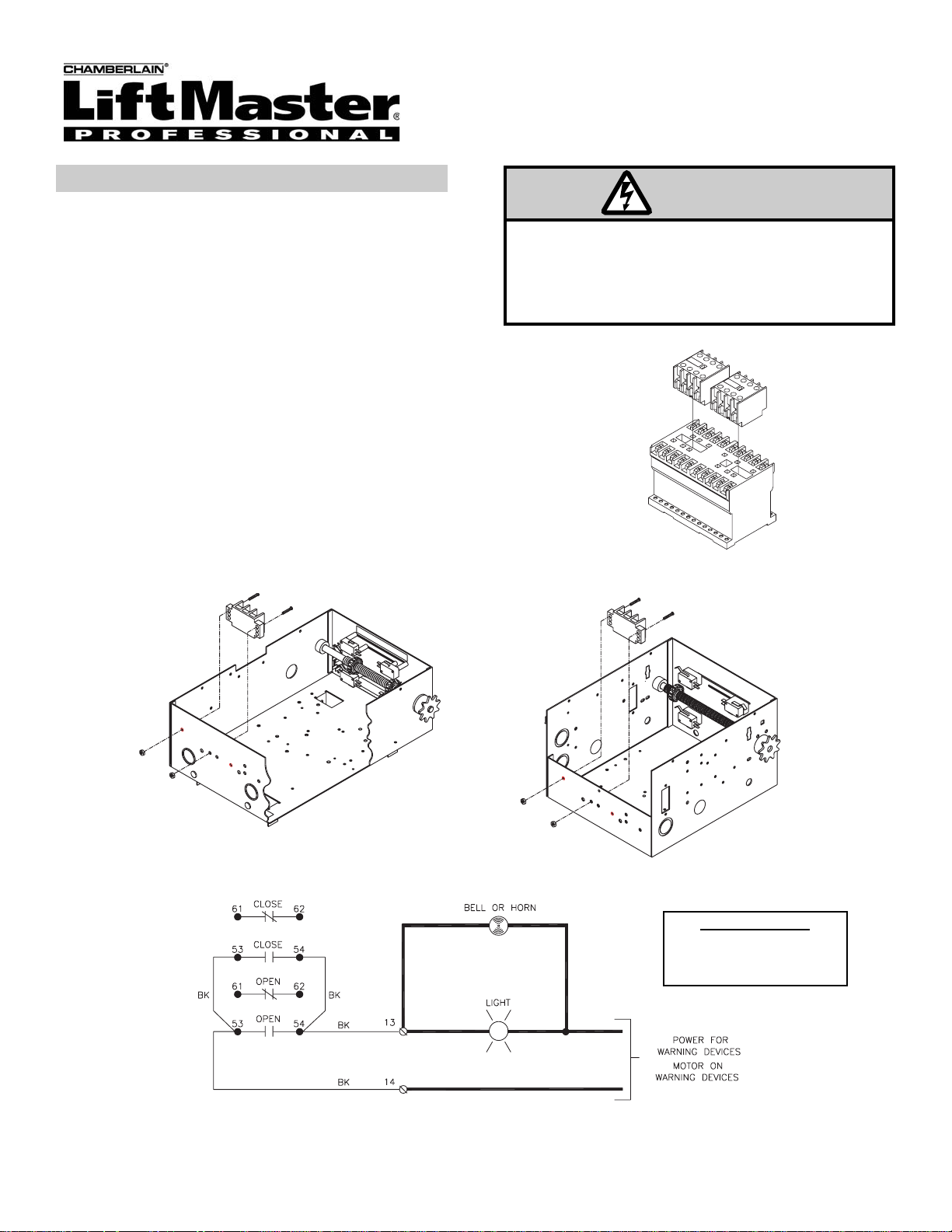
2. Install (2) new contact blocks to top of existing contactor.
See figure 1.
3. Install new 3 pole terminal block to electrical box using the
(2) screws and nuts supplied. See figure 2.
4. Install the new terminal block label over or under the terminal block based on position.
5. Wire the unit as shown below and refer to figure 3.
a) Connect a 4” black jumper between #53 on the
open contact block and #53 on the closed contact
block.
b) Connect a 4” black jumper between #54 on the
open contact block and #54 on the closed contact
block.
c) Connect a 12” black wire between #53 on the
open contact block to #14 on the terminal block.
d) Connect a 12” black wire between #54 on the
open contact block to #13 on the terminal block.
INSTALLATION INSTRUCTIONS
© 2003, The Chamberlain Group, Inc.
01-19933A All Rights Reserved
FIGURE 1
FIGURE 2
FIGURE 3
IMPORTANT
WARNING DEVICES WILL
BE ON WHENEVER THE
MOTOR IS RUNNING
WARNING
 Loading...