

Lift-master 71 909206 3 User Manual

APPLICATION
This modification is standard on model GH-300. Not for use
with solid state logic control boards (L).
• The operator must have C2/B2 wiring (not for medium
duty operators).
• Recommended for heavy doors and where frequent
reversing may be expected due to high usage.
FUNCTIONS
Modifies the operator control circuit so the the door must
stop for one second before reversing, in either direction.
This delay allows the door and operator to come to a more
complete stop than would happen if there was no delay.
• Prevents shock loading of the door and operator
especially if a safety device or other open override is
activated during closing, resulting in a longer life of the
operator.
• This delay has no effect on starting an operator that has
been stopped for longer than 2 seconds.
PREPARATION
Unpack kit to verify the parts listed at right are included.
Refer to installation instructions on reverse side.
DESCRIPTION QTY
Delay-on-reverse instruction sheet 1
Wiring diagram 1
Relay, 24VDC coil, DPDT 1
Wire ties 5
Auxilary contact block, 1NO & 1NC 2
Time delay assembly 1
Pan head phillips screw, #6-32 x 3/8" 2
#6 Tinnerman 2
Orange wire, 10" 18GA. 3/16" faston x 1/4" fork 1
Orange wire, 4-1/2" 18GA. 1/4" fork x 1/4" fork 1
Purple wire, 10" 18GA. 3/16" faston x 1/4" fork 1
Red wire, 16" 18GA. 3/16" faston x .110" faston 1
Yellow wire, 14" 18GA. 3/16" faston x .110" faston 1
Yellow wire, 4-1/2" 18GA. 1/4" fork X 1/4" fork 1
Yellow wire 9" 18GA. 1/4" fork x 1/4" fork 1
DELAY-ON-REVERSE 3 PH
MODIFICATION
K-LINE71-909206-3 MODELS T, GT, J, H, GH, SD & GSD
STANDARD DOOR OPERATORS WITH 24V CONTROL CIRCUITS
PACKING LIST
© 2006, The Chamberlain Group, Inc.
01-11605F All Rights Reserved
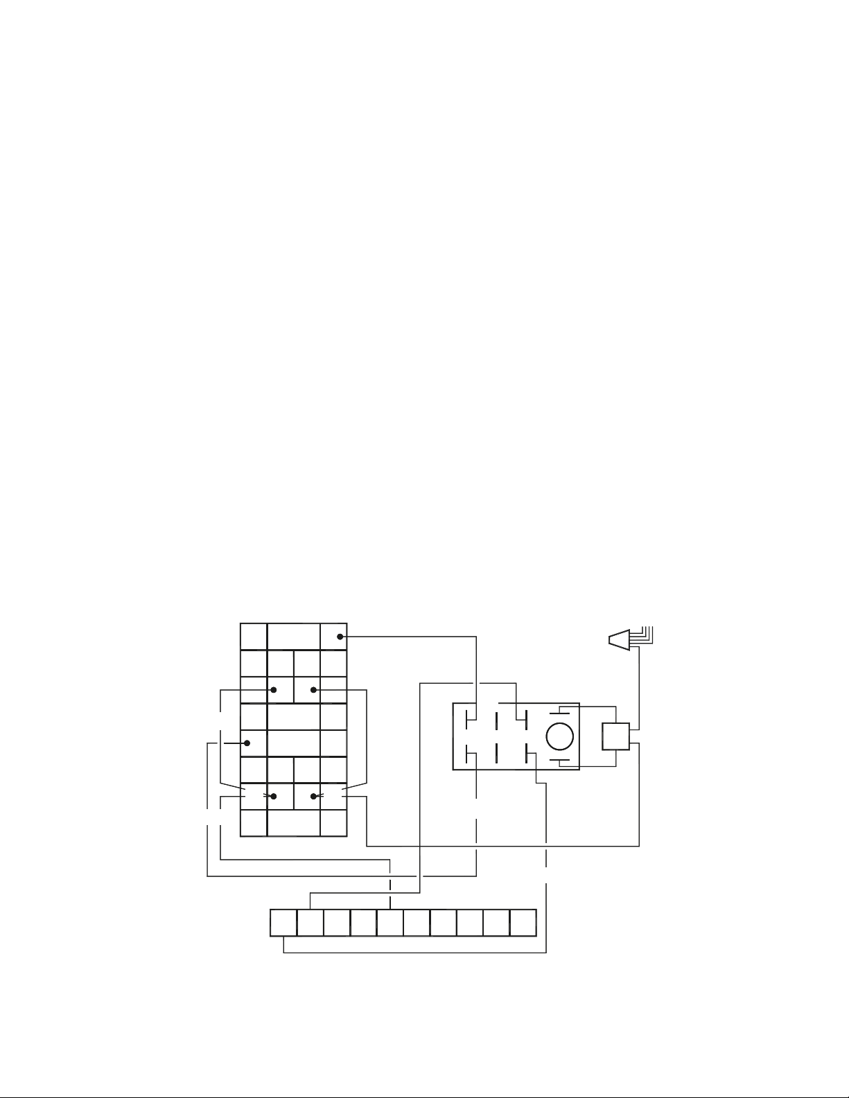
5. Locate the purple wire that connects terminal 2 to
terminal 14 on the closed side of the contactor. Remove
this wire from the operator.
Install a new purple wire from terminal 2 to the second
common on the TD relay. Connect a new red wire from
the normally closed (NC) on the TD to terminal 14 on
close side of contactor where the purple wire was
removed.
6. Use a yellow wire to connect terminal 5 to terminal 53 on
the auxiliary open contact block. Use a yellow jumper
wire to connect 53 on the auxiliary open contact block to
53 on the auxiliary close contact block.
7. Plug the delay assembly on to the two coil prongs of the
TD relay. It does not matter which connector is on which
prong. Locate the wire nut coming off the yellow wire
from the transformer and add the white wire from this
assembly into the wire nut with the four wires that are
already in the assembly.
8. Connect the orange wire from the delay assembly to 54
on the auxiliary open contact block. Use an orange
jumper wire to connect 54 on the the auxiliary open
contact to 54 on the auxiliary close contact (figure 1).
9. Reconnect power to operator.
1. Disconnect power.
2. Install the auxiliary contact blocks on top of the reversing
contactor. These blocks install by sliding them into slots
from the odd numbered side towards the even numbered
side. When they are fully on they will click into place and
will not slide off without pressing the release lever, a
small screwdriver may be needed to press it in. If any
wires were pushed aside during installation be sure to
separate them so that wires on adjacent prongs do not
touch.
3. Install the 24VDC, DPDT relay provided using existing
holes in the electrical box on the side of the box nearest
terminals L1, L2 and L3. This is the TD relay.
4. Locate the orange wire that goes from terminal 1 on the
terminal block to prong 13 on the open half of the
contactor. Remove this wire from the operator. Install a
new orange wire from terminal 1 to one common (C)
prong on the TD relay. Find the normally closed (NC)
prong on the TD relay that goes with this common and
connect this NC with a yellow wire to prong 13 on the
open half of the contactor where the original wire was
removed.
13
14
5
6
3
4
1
2
5
6
13
14
3
4
1
2
53
54
61
62
53
54
61 62
CLOSE
OPEN
OPEN
CLOSE
1 2 3 4 5 7 10 L1 L2 L3
Coil
N.C.
N.O.
C.
TD
Assy.
Exisiting
Wire Nut
WH
OR
OR
YE
PU
YE
YE
YE
OR
RD
PU
Figure 1
 Loading...