

Page 1
COURTESY LIGHT
MODIFICATION
MEDIUM DUTY OPERATORS
APPLICATION REQUIREMENTS:
This modification is available to models MT and MJ/MH Medium Duty door operator with 115VAC line voltage.
FUNCTIONS:
Provides a light socket on the operator control enclosure. The light will turn on when the door starts to open and
remains on for several minutes. Similar to the courtesy light in a standard residential garage door opener.
PREPARATION:
Unpack kit to verify the parts listed below are included. Refer to installation instructions on reverse side.
PART NUMBER
76-18741
27-10199
27-12015
80-362-1
82-PX08-10T
84-LH-08
95-YE15-69
96-BK09-16
96-WH09-16
96-RD15-66
LIGHT DELAY ASSY., MEDIUM DUTY
WIRE TIE
LIGHT SOCKET
BLUE WIRE NUT
SCREW, #8-32 X 5/8” LONG, PAN HEAD, PHILLIPS
LOCKNUT, #8-32
WIRE, YELLOW, 15” LONG, 1/4” FORK X 1/4” FASTON
WIRE, BLACK, 9” LONG, STRIP X 1/4” FORK
WIRE, WHITE, 9” LONG, STRIP X 1/4” FORK
WIRE, RED, 15” LONG, 1/4” FORK X 1/4” FORK
DESCRIPTION
INSTALLATION INSTRUCTIONS
TO AVOID SERIOUS PERSONAL INJURY OR
DEATH FROM ELECTROCUTION, DISCONNECT
ELECTRIC POWER TO OPERATOR BEFORE
INSTALLING LIGHT DELAY KIT.
QUANTITY
1
5
1
2
2
2
1
1
1
1
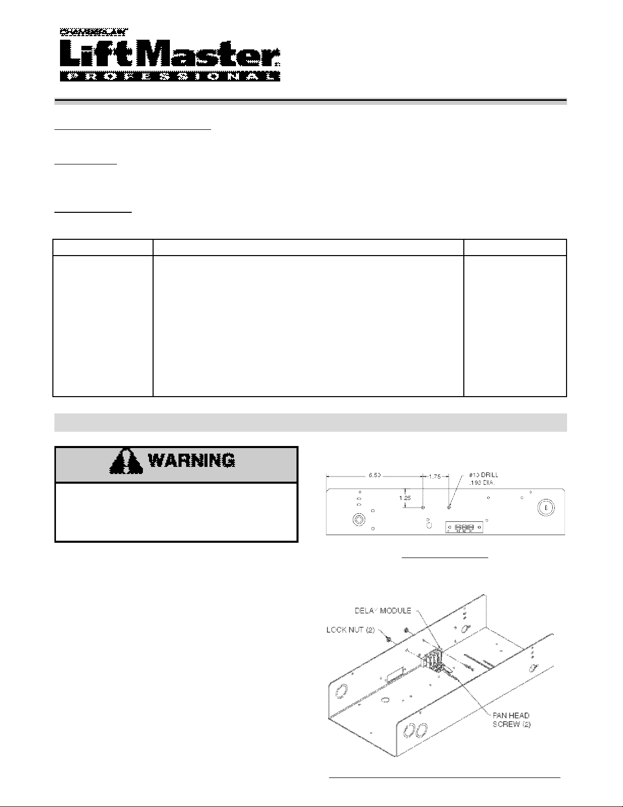
FIGURE 1: HOLE LOCATION
STEP 1: INSTALL LIGHT DELAY ASSEMBLY
1. Locate two holes on inside of electrical box on the
radio block side.
NOTE: If holes don’t exist, add holes using a #10
drill, .193 DIA. (Refer to figure 1 for location).
2. Secure delay module assembly in place with (2)
#8-32 pan head screws and lock nuts supplied (Refer
to figure 2 for additional reference).
RADIO BLOCK SIDE
FIGURE 2: MODULE LOCATION
COMPONENTS NOT SHOWN FOR EASE OF VIEWING
Page 2
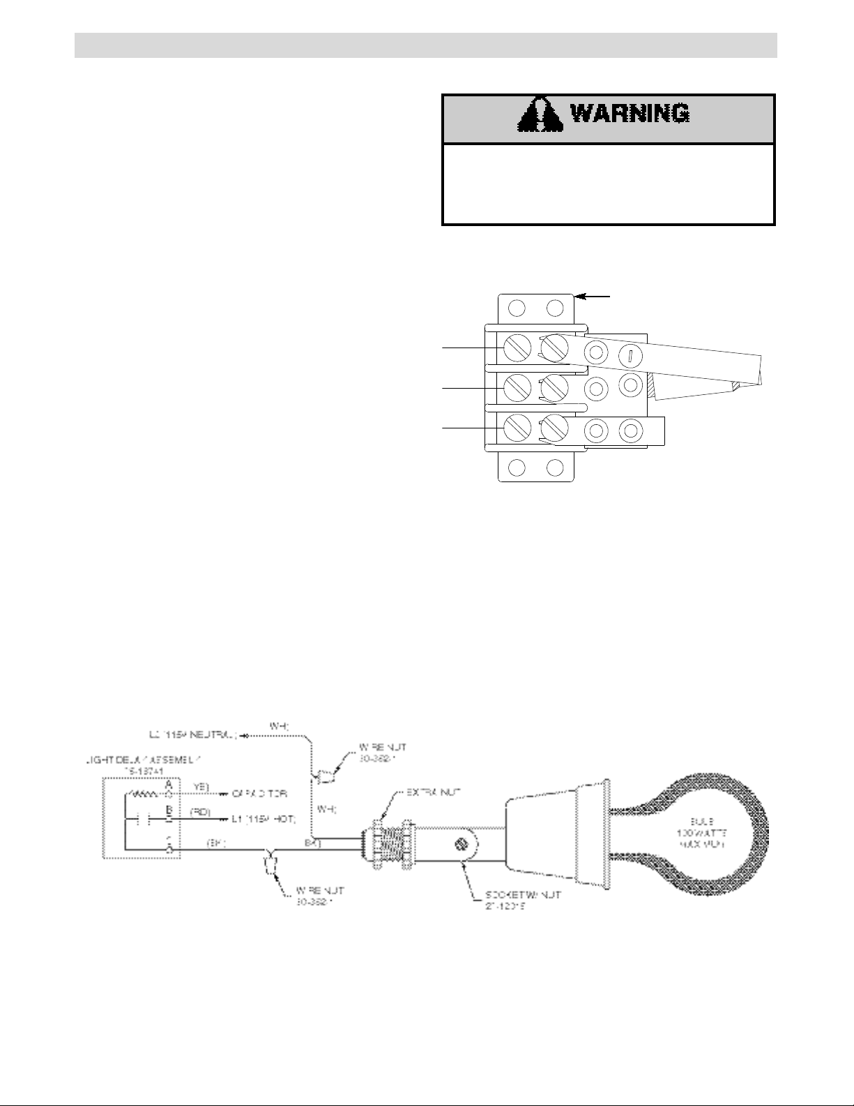
INSTALLATION INSTRUCTIONS CONT’D
STEP 2: WIRING DELAY ASSEMBLY
1. Connect a new yellow wire from (A)on the light
delay to the spare terminal on the capacitor.
2. Connect a new red wire from terminal (B)on the
light delay to L1 (115V-HOT)on the terminal block.
TO AVOID SERIOUS PERSONAL INJURY OR
DEATH FROM ELECTROCUTION, DISCONNECT
ELECTRIC POWER TO OPERATOR BEFORE
INSTALLING LIGHT DELAY KIT.
3. Connect a new black wire from terminal (C)on the
light delay to one of the wire nutsprovided.
4. Connect the black wire from the light socketto
the wire nut in #3.
5. Connect the white wire from the light socketto
the other wire nutsupplied.
6. Connect a new white wire from the wire nut in #5
to L2 (115V-NEUTRAL)on the terminal block.
FIGURE 4: WIRING
FIGURE 3: TERMINAL CALLOUT
LIGHT DELAY
ASSEMBLY #76-18741
C
B
A
NOTE: Delay module shown straightened for ease of
viewing.
01-12157C All Rights Reserved
© 2000, The Chamberlain Group, Inc.
 Loading...