

Page 1
COURTESY LIGHT
MODIFICATION
STANDARD OPERATORS
71-2954028
APPLICATION REQUIREMENTS:
This wiring modification is available to models T, GT, APT, J, H, GH, SD and GSD
standard door operator with 115VAC line voltage.
FUNCTIONS:
Provides a light socket on the operator control enclosure. The light will turn on when
the door starts to open and remains on for several minutes. Similar to the courtesy light
in a standard residential garage door opener.
PREP
ARATION:
Unpack kit to verify the parts listed below are included. Refer to installation instructions
on reverse side.
PACKING LIST
PART NUMBER
01-12014
27-10199
27-12015
27-8002-K
28-1007
76-18686
80-362-1
82-PX08-10T
84-LH-08
96-BK08-66
96-WH09-66
96-BK08-16
96-BK14-66
96-RD14-16
Courtesy Light Modification Instructions For Standard Operators
Wire Tie, 5-1/2”
Light Socket With Nut
Auxiliary Contact Block
1/2” Locknut
Light Delay Assembly
Blue Wire Nut
Screw, #8-32 x 5/8” long Pan Head Phillips
#8 Locknut
Wire, Black 16GA. 8”, .250 Fork x .250 Fork
Wire, White 16GA 9”, .250 Fork x .250 Fork
Wire, Black 16GA 8”, Strip x .250 Fork
Wire, Black 16GA 14”, 250 Fork x .250 Fork
Wire, Red 16GA 14”, Strip x .250 Fork
DESCRIPTION
QUANTITY
1
5
1
2
1
1
2
2
2
3
1
1
1
1
Page 2
INSTALLATION INSTRUCTIONS
WARNING
WARNING
4. Connect the wires as follows (refer to figures 3-5
for clarity).
TO AVOID SERIOUS PERSONAL INJURY OR
DEATH FROM ELECTROCUTION, DISCONNECT
ELECTRIC POWER TO OPERATOR BEFORE
INSTALLING LIGHT DELAY KIT.
1. Before Proceeding be sure the Auxiliary Contact
blocks supplied in this kit will fit your contactor.
2. Once you have determined that the contactor
blocks are correct install one on each half of the
reversing contactor. The blocks slide on from the odd
numbered side to the even numbered side. Be sure
that they snap into place and cannot be slid back
without pressing the release lever. It may be
necessary to bend some wires out of the way to
install the blocks. Be sure to bend the wires back and
to take care that wires on adjacent terminals do not
touch each other.
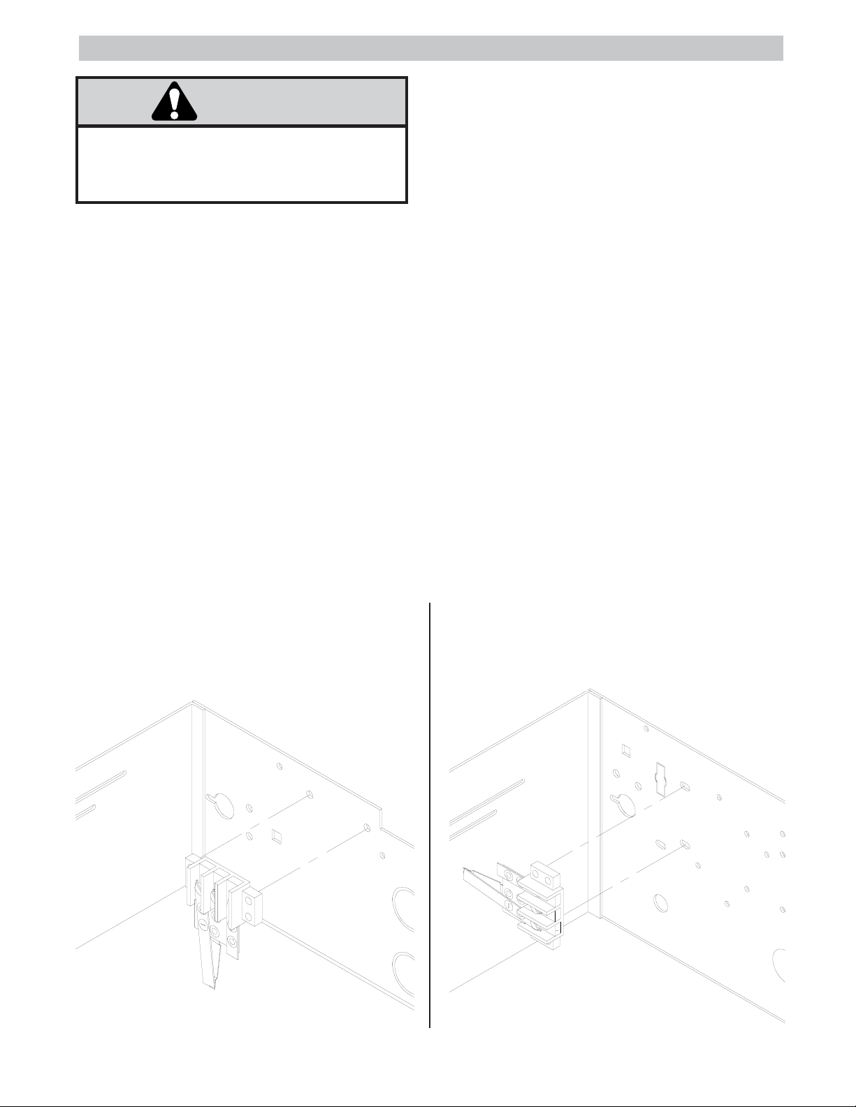
3. Install the light delay module into the control box
(see figures 1 and 2). Also install the light socket
(see figure 6). If the light socket is to be installed on
the control box, knock out one of the knockouts and
secure the socket with a nut on each side of the sheet
metal.
a) Long black wire from 115V-HOT (terminal L1 on
115V operators) to terminal #53 of the open-direction
contactor block.
b) Black wire from #53 of one contact block to #53 of
other contact block.
c) Black wire from #54 of one contact block to #54 of
other contact block.
d) Black wire from #54 of the open-direction contact
block to terminal (A) of light delay module.
e) Black wire from #53 of the close-direction contact
block to the black wire of the lightbulb-socket
(connect with wire nut).
f) Red wire from terminal (C) of light delay module
to the white wire of the lightbulb-socket (connect with
wire nut).
g) White wire from terminal (B) of the light delay
module to 115V-NEUTRAL (terminal L2 on 115V
operators).
5. Do not exceed 100 total watts with your Bulb(s).
FIGURE 1- Mounting location of light-delay
module for Models T, GT, APT,
SD and GSD
FIGURE 2- Mounting location of light-delay
module for Models J, H and GH
2
Page 3
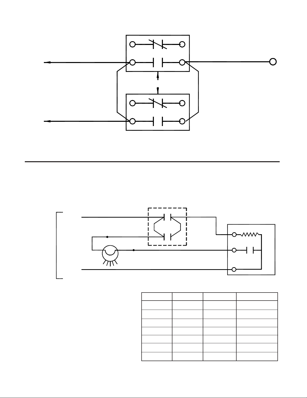
FIGURE 3- Detail on auxiliary contact block connections:
OPEN DIRECTION
61
BLACK
53
115V-HOT
AUXILIARY CONTACT BLOCKS
BLACK
JUMPER
61
BLACK
53
BLACK WIRE OF LIGHT
(CONNECT BY WIRE-NUT)
CLOSED DIRECTION
FIGURE 4- Courtesy-light modification wiring diagram:
62
54
62
54
BLACK
LIGHT-DELAY
TERMINAL (A)
BLACK
JUMPER
115V
FOR
LIGHT
(HOT)
(NEUT)
BK
AUXILIARY
CONTACT BLOCKS
OP
53
L
54
O
LIGHT
DELAY
WH
M
P
CL
53
R
54
N
Q
A
C
B
KEY TO WIRES:
LETTER
L
M
N
O
P
Q
R
COLOR
BLACK
BLACK
BLACK
BLACK
BLACK
RED
WHITE
LENGTH
14”
8”
8”
8”
8”
14”
9”
TYPE
FORK-FORK
FORK-FORK
FORK-FORK
FORK-FORK
FORK-STRIPPED
FORK-STRIPPED
FORK-FORK
3
Page 4

FIGURE 5- Light-delay module terminals:
C
B
A
LIGHT DELAY ASSEMBLY #76-18686
FIGURE 6- Detail on light-bulb assembly:
TO TERMINAL C OF LIGHT DELAY MODULE
WH
BK
EXTRA NUT
TO TERMINAL #53 OF THE CLOSED DIRECTION AUXILIARY CONTACT BLOCK
BULB
100 WATTS
MAXIMUM
27-12015 SOCKET WITH NUT
01-12014D All Rights Reserved
© 1998, The Chamberlain Group, Inc.
 Loading...