

Page 1
1
DUAL AUXILIARY TROLLEY
MODIFICATION
For Use With Models J, H and GH
659213-XX AND 6592131-XX
APPLICATION
This modification is available for model J, H and GH operators.
For 1/2 HP and lower side mount operators use #48 drive chain.
For 3/4 HP and higher side mount operators use #41 drive chain.
FUNCTIONS
Provides trolley type operation on wide standard lift doors where
a side mount operator is preferred over a draw bar operator.
NOTE: Use the Model "T" owner’s manual for trolley installation,
where appropriate, with the following exceptions:
TRACK ASSEMBLY
1. Assemble both tracks by installing the track spacers (Figure 2).
2. Install the idler assemblies onto the wall end of the tracks. One
idler assembly is set up with a coupling sprocket on each end,
and the other idler is set up with only one coupling sprocket.
3. Slide the slider assembly into both tracks from the open end.
Be sure that the take-up bolt is facing the open end of the track.
4. Install the idler roller assemblies onto the open end of the
tracks.
5. Install the chain, use the take-up bolt to adjust the chain
tension to allow about 3" sag in the center (remove links
if necessary).
6. Determine which side of the door the operator will be mounted
on and install the track with the double idler on that side at the
center of the opening.
7. Install the track assembly with the single idler on the other side
of the center of the opening. Brace the tracks appropriately.
CONNECT TRACKS
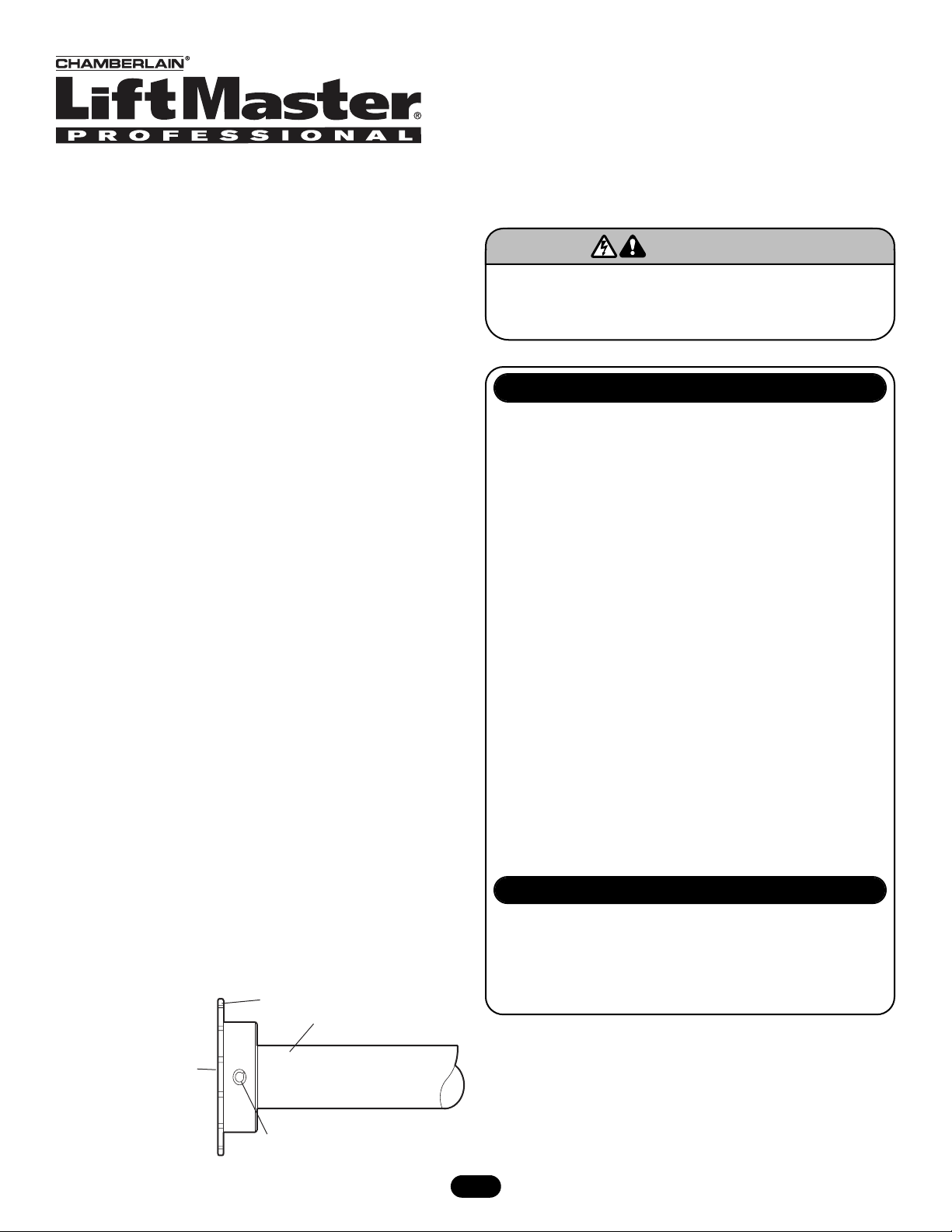
1. Determine the length of the shaft needed to couple the two
tracks together and cut the shaft provided to that length. Slide
two bearing assemblies on the end of the shaft.
2. Install a 48B14 sprocket on each end of the shaft using the
(2) 1/4" x 1-1/2" roll pin provided (Figure 1).
3. Use a tape measure to set the slider assemblies the same
distance from the wall.
4. Couple the shaft between the two idler assemblies by butting
the 14 tooth sprockets together and connect with a #40 chain
and master link (Figure 2).
NOTES: 1. Shipped with 1/2 HP and lower side mount operators.
2. Shipped with 3/4 HP and higher side mount
operators.
PART # DESCRIPTION QTY
Model "T" Owner’s Manual 1
10-10203 Curved Arm 2
10-10204 Door Bracket 2
10-10205 Front Bracket 2
12-11438 Bearing 4
15-48B14LXX Sprocket 48B14 1" Bore 3
15-50B35LGH Sprocket 50B35 1" Bore
1/4" KW (2) 5/16-18 SS 1
75-10170 Slider 2
75-10214 Straight Arm 2
K75-10259 Track Spacer See Chart
75-11502 Drive Chain Front Idler #48 See Note 1
75-11503 Drive Chain Front Idler #41 See Note 2
75-11544 Drive Chain Double Idler #41 See Note 2
K75-11545 Chain Double Idler #48 Drive See Note 1
80-10383 Key Ring 1-1/4" See Chart
86-RP08-108 Long Roll Pin 1/4" x 1-1/2" 2
PACKING LIST
VARIABLE PARTS
PART #
K75-10259
80-10383
DESCRIPTION
Track Spacer
Key Ring 1-1/4"
DOORS
12'-14''
0
0
DOORS
16'-20'
2
2
DOORS
22'-24'
4
2
DOORS
TO 26'
6
2
FIGURE 1
To prevent possible SERIOUS INJURY or DEATH, disconnect
electric power to operator BEFORE installing. ALL electrical
connections MUST be made by a qualified individual.
WARNING
WARNING
NOTE: XX is door height.
48B14 Sprocket 1" Bore
1" Diameter Shaft
Be Sure Shaft is Flush With
Sprocket. Do Not Let Shaft
Protrude Beyond Sprocket.
Drill 1/4" Hole - Pin
with 1/4"x1-1/2" Roll Pin
Page 2
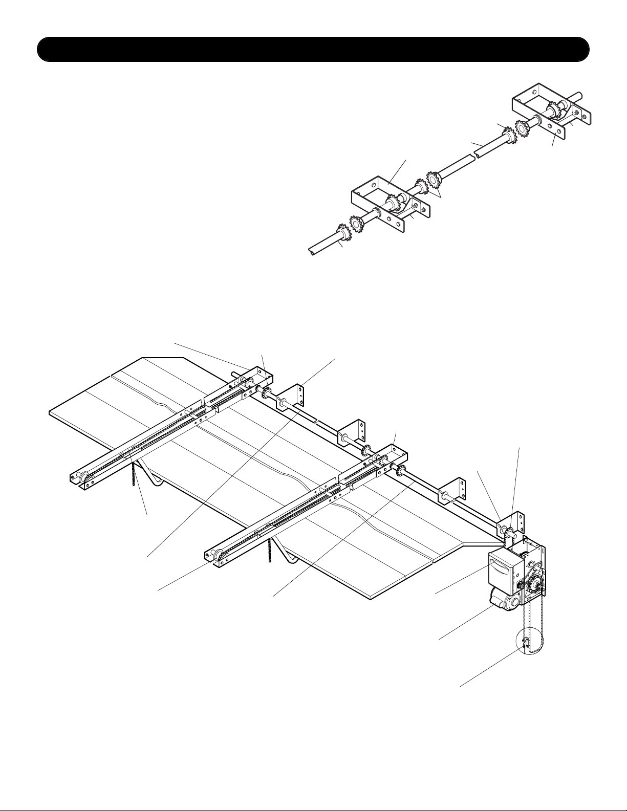
INSTALLATION
FIGURE 2
© 2005, The Chamberlain Group, Inc.
01-12575E All Rights Reserved Printed in Mexico
NOTES:
1. Smaller sprocket (50B12) is mounted on the extension shaft.
2. Larger sprocket (50B35) is mounted to the operator where the
(50B12) sprocket was removed.
3. Bearing assembly should be mounted as close to the (50B12)
sprocket as possible to prevent shaft flex.
4. Refer to owner’s manual for instructions on reversing limits.
Front Idler Assembly
Chain Coupling
(3 Places)
Bearing Assembly
(4 Places)
Extension Shaft
Sprocket 50B12
(See Note 1)
GH, H, J Operator
(With Reversed Limits
Logic 3 Requires Removal
of Jumper)
Disconnect Bracket
Idler Roller
(2 Places)
Sprocket 50B35
(See Note 2)
See Note 3
Double Idler Assembly
Connecting Shaft
Slider Assembly
(2 Places)
FIGURE 3
INSTALL OPERATOR
1. Install the operator using the appropriate manual.
2. Determine the length of shaft needed to connect the operator
to the double idler assembly and cut the shaft provided to that
length.
3. Install the last 48B14 sprocket to one end of the extension
shaft with the 1/4" x 1-1/2" roll pin provided (Figure 3).
4. Slide the last two bearing assemblies onto the end of the shaft.
Place one of the bearings in the center of the shaft. The other
bearing should be placed as close to where the operator driven
sprocket will be.
5. Remove the 50B12 sprocket from the operator and replace it
with the 50B35 sprocket provided. Install the 50B12 sprocket
on the extension shaft just installed.
Extension Shaft,
Runs to Operator
Connecting Shaft
Double Idler Assembly
Couple Sprockets Together with
#40 Chain and Master Link
Track
Spacer
48B14 Sprocket
Track
Spacer
Single Idler Assembly
 Loading...