


Models X5i, X5, X3i, and X3 Cross-Trainers
Customer Support Services
SERVICE MANUAL

Life Fitness Models X5i, X5, X3i and X3 Cross-Trainers
INTRODUCTION
HOW TO USE SERVICE MANUAL AND CONTACT CUSTOMER SUPPORT SERVICES
This service manual is applicable to Cross-Trainer Models X5i, X5, X3i and X3. Illustrations in this service manual represent typical configurations and may differ slightly from actual equipment. The Service Manual provides safe and efficient step-by-step service operations. This manual consists of:
TABLE OF CONTENTS
Section I
qTROUBLESHOOTING Section II
qDIAGNOSTIC
Section III
qHOW TO...SERVICE AND REPAIR Section IV
qELECTRONICS
Section V
q MISCELLANEOUS
When an operating problem occurs, refer to troubleshooting guides and diagnostic mode to isolate the cause. When applicable, guides are listed by problem symptom followed with suggestions of probable cause(s).
Once the source of problem is identified, consult the "How To..." guides for recommended repair procedures. "How To..." sub-sections are organized by replaceable part or assembly name. For convenience, sub-section lists recommended “Tools Required” to complete specific function. Refer to PARTS IDENTIFICATION to identify proper name and number of part to order for repair of equipment.
A reproducible FAX order claim form is given in COMMUNICATING BY TELEFACSIMILE for convenient ordering of service parts.
To order parts, contact Life Fitness Customer Support Services. Via FAX - 24 hrs. /day, 7 days/week.
Via telephone - Monday through Friday from 8:00 AM to 5:00 PM Central Standard Time. Via post - At address cited.
To speed Life Fitness Customer Support Services response to your needs, please provide:
∙Model number,
∙Serial number,
∙Symptom, and
∙Part name and number
Before installing part, review "How To..." and follow step by step procedures recommended to install part safely and efficiently. If you have questions or comments please telephone, FAX or, write us. We are:
LIFE FITNESS - CUSTOMER SUPPORT SERVICES
10601 Belmont Avenue; Franklin Park, IL 60131; U.S.A.
Telephone: 847.451.0036 |
Toll-free: 800.351.3737 |
|
FAX: 847.288.3702 |
Toll-free: 800.216.8893 |
|
i

Life Fitness Models X5i, X5, X3i, and X3 Cross-Trainers
TABLE OF CONTENTS
SECTION I TROUBLESHOOTING GUIDES |
PAGE |
SLIGHT “BUMP” OR “HITCH” ......................................................................................... |
3 |
CLUNKING NOISE........................................................................................................ |
3 |
METALLIC SCRAPING NOISE....................................................................................... |
3 |
NO SPEED READOUT ON CONSOLE VERSION 1......................................................... |
3 |
NO SPEED READOUT ON CONSOLE VERSION 2......................................................... |
3 |
CONSOLE IS NON OPERATIVE.................................................................................... |
3 |
CONSOLE ERRATIC .................................................................................................... |
4 |
DIM OR NOT FUNCTIONING LED SEGMENTS ............................................................... |
4 |
BUTTONS NOT FUNCTIONING ON EZ USER PAD ......................................................... |
4 |
BUTTONS NOT FUNCTIONING ON CONSOLE ............................................................... |
4 |
ERRATIC HEART RATE ................................................................................................ |
4 |
NO HEART RATE READOUT ........................................................................................ |
4 |
AT POWER UP #8’S APPEAR ON CONSOLE AND BEEPS............................................ |
4 |
UNIT DOES NOT CHANGE RESISTANCE ...................................................................... |
4 |
SECTION II DIAGNOSTIC MODES (DELUXE MONITOR) |
|
ENTERING DIAGNOSTICS MODE ................................................................................. |
3 |
TOGGLING THROUGH DIAGNOSTIC STATES................................................................ |
3 |
DIAGNOSTIC STATE 1 – SOFTWARE VERSION NUMBER............................................. |
4 |
DIAGNOSTIC STATE 2 – KEYPAD TEST MODE ............................................................ |
5 |
DIAGNOSTIC STATE 3 – DISPLAY TEST MODE ............................................................ |
6 |
DIAGNOSTIC STATE 4 – MAGNET POSITION................................................................ |
7 |
DIAGNOSTIC STATE 5 – RUN TEST.............................................................................. |
8 |
DIAGNOSTIC STATE 6 – SPEED READING TEST.......................................................... |
9 |
DIAGNOSTIC STATE 7 – HEART RATE TEST ................................................................ |
10 |
DIAGNOSTIC STATE 8 – EEPROM VERSION NUMBER................................................. |
11 |
DIAGNOSTIC STATE 9 – RUN TIME .............................................................................. |
12 |
DIAGNOSTIC STATE 10 – DISPLAY TEST..................................................................... |
13 |
DIAGNOSTIC STATE 11 – PHOTO SHOOT MODE.......................................................... |
14 |
SECTION II DIAGNOSTIC MODES (STANDARD MONITOR) |
|
ENTERING DIAGNOSTICS MODE ................................................................................. |
15 |
TOGGLING THROUGH DIAGNOSTIC STATES................................................................ |
15 |
DIAGNOSTIC STATE 1 – SOFTWARE VERSION NUMBER............................................. |
16 |
DIAGNOSTIC STATE 2 – DISPLAY TEST MODE ............................................................ |
17 |
DIAGNOSTIC STATE 3 – KEYPAD TEST MODE ............................................................ |
18 |
DIAGNOSTIC STATE 4 – MAGNET POSITION................................................................ |
19 |
DIAGNOSTIC STATE 5 – RUN TEST.............................................................................. |
20 |
DIAGNOSTIC STATE 6 – PHOTO SHOOT MODE ........................................................... |
21 |
ii

Life Fitness Models X5i, X5, X3i, and X3 Cross-Trainers
TABLE OF CONTENTS
SECTION III SERVICE AND REPAIR GUIDE |
|
SERVICE AND REPAIR GUIDE ..................................................................................... |
3 |
SIDE SHROUDS .......................................................................................................... |
4 |
PEDAL LEVER COMPONENTS .................................................................................... |
8 |
IDLER AND COUPLER ASSEMBLY COMPONENTS ...................................................... |
9 |
DRIVE BELT AND FLYWHEEL ASSEMBLY - VERSION 1 .............................................. |
10 |
DRIVE BELT AND FLYWHEEL ASSEMBLY - VERSION 2 .............................................. |
11 |
CONSOLE SUPPORT COLUMN.................................................................................... |
12 |
CONSOLE ASSEMBLY ................................................................................................ |
13 |
REAR WHEELS AND FRONT LEVERERS ..................................................................... |
14 |
PEDALS ...................................................................................................................... |
15 |
EDDY CURRENT ASSEMBLY - VERSION 1 .................................................................. |
16 |
SPEED MOTOR ASSEMBLY - VERSION 2.................................................................... |
17 |
OPTO SENSOR - VERSION 1....................................................................................... |
18 |
REED SWITCH - VERSION 2........................................................................................ |
19 |
SECTION IV ELECTRONIC OVERVIEW AND WIRING BLOCK DIAGRAM |
PAGE |
CABLES VERSION 1.................................................................................................... |
3 |
CABLES VERSION 2.................................................................................................... |
4 |
SECTION V MISCELLANEOUS INFORMATION |
|
SERIAL AND MODEL NUMBERS .................................................................................. |
3 |
PREVENTIVE MAINTENANCE TIPS .............................................................................. |
4 |
iii

Life Fitness Models X3i, X3, X5i, and X5 Cross-Trainers
SECTION I
TROUBLESHOOTING GUIDE
1

Life Fitness Models X3i, X3, X5i, and X5 Cross-Trainers
TROUBLESHOOTING GUIDE
Notes:
2

Life Fitness Models X3i, X3, X5i, and X5 Cross-Trainers
TROUBLESHOOTING GUIDE
SYMPTOM |
PROBABLE CAUSE |
CORRECTIVE ACTION |
|
|
|
|
|
Slight “bump” or “hitch” in |
Pivot points are not broken in. |
Remove all clevis covers and loosen all six |
|
pedal motion. |
|
bolts that connect links to clevis brackets. |
|
|
|
Loosen the nuts a couple of turns so the |
|
|
|
machine can still be operated. Operate the |
|
|
|
machine a few revolutions to help seat the |
|
|
|
pivot points. Retighten the six bolts and |
|
|
|
install the clevis covers. |
|
|
|
|
|
|
Levelers are not in contact with the |
Levelers must be in contact with the floor. |
|
|
floor. |
Make sure that the leveler jam nuts are also |
|
|
|
properly tightened. |
|
|
|
For further assistance, contact Life Fitness |
|
|
|
Customer Support Services. |
|
|
|
|
|
Clunking noise. |
Damaged washers, retaining rings, |
Remove the clevis covers, and check for |
|
|
or wave springs. |
damaged washers, retaining rings, and wave |
|
|
|
springs. If necessary, replace. Remove the |
|
|
|
end caps from lower link arm, and then |
|
|
|
remove the bolt. Check that retaining ring is |
|
|
|
correctly installed. Repeat for all pivot areas. |
|
|
|
|
|
Metallic scraping noise |
Magnet is rubbing on the aluminum |
Remove bottom rear shroud (See How To…) |
|
occurs in forward or reverse |
disk or chopper wheel may be |
and inspect the position of the magnets to see |
|
direction. |
hitting the OPTO Sensor. Applies |
if they are rubbing on the aluminum disk. If so, |
|
|
only to Version 1 units. |
re-center the OPTO Sensor. |
|
|
|
|
|
No speed readout on console. |
Loose connections between the |
Verify that the connections between the |
|
Applies only to Version 1 |
OPTO sensor and wiring harness. |
OPTO sensor and wiring harness are secure. |
|
units. |
|
|
|
Chopper wheel is not spinning |
Bend the OPTO bracket slightly upwards. |
||
|
|||
|
between the two tabs of the OPTO |
|
|
|
sensor. |
|
|
|
|
|
|
No speed readout on console. |
Magnet missing or faulty reed |
Check for missing magnet or replace switch. |
|
Applies only to Version 2 |
switch. |
|
|
units. |
|
|
|
|
|
|
|
Console is out, non-operative. |
Transformer is not plugged in. |
Verify that the transformer is plugged in. |
|
|
Wiring harness is not connected to |
Verify that the wiring harness is connected to |
|
|
the console. |
the console. |
|
|
Pinched wire harnesses. |
Check wiring harness in upright tube or at the |
|
|
|
base frame. Verify that the harnesses are |
|
|
|
properly connected. |
|
|
|
If all connections are correct, replace |
|
|
|
transformer, if this does not solve the problem |
|
|
|
then replace console. |
|
|
|
|
3

Life Fitness Models X3i, X3, X5i, and X5 Cross-Trainers
TROUBLESHOOTING GUIDE
SYMPTOM |
PROBABLE CAUSE |
CORRECTIVE ACTION |
|
|
|
Console erratic. |
Clock within the console not |
Replace the console. |
|
functioning or the memory chip is |
|
|
corrupted. |
|
|
|
|
Dim or not functioning LED |
Defective console. |
Test console in diagnostics. Replace console |
segments on displays. |
|
if necessary. |
|
|
|
Buttons not functioning on EZ |
Bad connection between EZ user |
Check connections between EZ user pod and |
user pod. |
pod and console. |
console. |
|
|
|
Buttons not functioning on |
Faulty connection at membrane |
Check the connection of the membrane switch |
console. |
switch of console. |
on the console. Look in the hole in the back of |
|
|
the console, the connector is on the bottom of |
|
|
the board assembly and to the right side of |
|
|
the hole. |
|
|
|
|
Defective keypad on console. |
Replace the console. |
|
|
|
Erratic heart rate. |
Receiver mounted incorrectly in |
Check that the mounting of the heart rate |
|
accessory tray. |
receiver in the accessory tray is secure and |
|
|
not loose. |
|
|
Verify that the receiver has been inserted into |
|
|
the foam tube. |
|
|
|
No heart rate readout. |
Faulty connection between receiver |
Check connections between the heart rate |
|
and console or faulty receiver. |
receiver and the console, or if faulty receiver, |
|
|
then replace the receiver. |
|
|
|
At power up, #8’s appear on |
This is a fault condition showing |
Verify that the Eddy current on Version 1 or |
the console and beep sounds |
that the Eddy current or Servo |
Servo Motor on Version 2 is connected to the |
(standard console). |
Motor is not moving or is not moving |
wiring harness. |
At power up, motor error |
to the location it’s supposed to. |
Test Eddy current or Servo Motor in |
|
||
appears on console and beep |
|
Diagnostic 4. |
sounds. |
|
If the display is functioning and the numbers |
|
|
|
|
|
on the left side of the display are changing in |
|
|
value with each key press but the magnet |
|
|
does not move and numbers on right side of |
|
|
display do not appear, then the Eddy current |
|
|
assembly needs to be replaced. |
|
|
If no number is shown on the left side of the |
|
|
display, then the console needs to be |
|
|
replaced. |
|
|
|
After beginning of program, |
Bad connection at Eddy Current or |
Verify the cable connection at the EDDY |
the unit does not change |
faulty Eddy Current. |
current assembly is properly connected. If all |
resistance, followed by “Motor |
|
connections are making proper contact, then |
Error” message on the |
|
replace the EDDY current assembly. |
display. |
|
|
|
|
|
4

Life Fitness Models X5i, X5, X3i, and X3 Cross-Trainers
SECTION II
DIAGNOSTIC MODES
1

Life Fitness Models X5i, X5, X3i, and X3 Cross-Trainers
NOTE
2
Life Fitness Models X5i, X5, X3i, and X3 Cross-Trainers
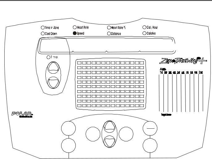
X5i, X5, X3i, and X3 Display Consoles
MESSAGE CENTER
My |
|
Clear |
|
Workouts |
|
||
Workout |
Pause |
||
|
|||
|
Enter |
||
|
Profiles |
||
|
|
||
Quick |
|
Cool |
|
Start |
|
Down |
X5i and X3i Deluxe Monitor
P1 |
|
|
|
P2 |
|
|
|
P3 |
|
|
|
P4 |
|
|
|
P5 |
|
|
|
P6 |
|
|
|
P7 |
Enter |
CT |
|
Workout |
|||
|
|||
Profile |
|
Reverse |
|
Quick |
Clear |
Cool |
|
Pause |
|||
Start |
|
Down |
X5 and X3 Standard Monitor
3

Life Fitness Models X5i, X5, X3i, and X3 Cross-Trainers
Diagnostic Mode For Deluxe Monitor
My |
Clear |
|
Workouts |
Pause |
|
Workout |
||
Enter |
||
Profiles |
||
Quick |
Cool |
|
Start |
Down |
ENTERING DIAGNOSTICS MODE
Diagnostics can only be entered from IDLE mode. Enter Diagnostics by pressing the Pause/Clear button twice, and then press the Cool Down button, sequence must be completed within 3 seconds, or the monitor returns to IDLE mode.
Upon entering the Diagnostics mode, the monitor will beep three times before entering Diagnostic State 1.
TOGGLING THROUGH DIAGNOSTIC STATES
Pressing the Enter button will advance to the next Diagnostic State. Diagnostics can only advance.
Once the Last State has been reached, pressing the Enter button again will exit the Diagnostic mode and the monitor will enter the IDLE mode.
4
Life Fitness Models X5i, X5, X3i, and X3 Cross-Trainers
Diagnostic Mode For Deluxe Monitor
Diagnostic State 1 - Software Version Number
X.XX
My |
|
Clear |
Workouts |
Workout |
Pause |
|
||
|
Enter |
|
|
Profiles |
|
|
|
|
Quick |
|
Cool |
Start |
|
Down |
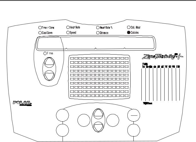
The Calories LED will light and the software version will be displayed in the message center.
5
Life Fitness Models X5i, X5, X3i, and X3 Cross-Trainers
Diagnostic Mode For Deluxe Monitor
Diagnostic State 2 - Keypad Test Mode
My |
|
Clear |
Workouts |
Workout |
Pause |
|
||
|
Enter |
|
|
Profiles |
|
|
|
|
Quick |
|
Cool |
Start |
|
Down |
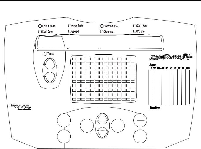
All LEDs will be off until the keypad buttons are pressed. The following is to be displayed while a button is held down button. An audible beep will occur with each key press.
BUTTON |
DISPLAY |
Time Ù |
“1111111111111111” |
Time Ú |
“2222222222222222” |
My Workouts |
“3333333333333333” |
Quick Start |
“4444444444444444” |
Workout Profile |
“5555555555555555” |
Level Ù (Main console) |
“6666666666666666” |
Level Ú (Main console) |
“7777777777777777” |
Clear/Pause |
“8888888888888888” |
Cool Down |
“9999999999999999” |
Enter |
This will advance the monitor the |
|
next diagnostic state #3. |
|
|
EASY POD NOT SHOWN |
|
Level Ù (on the EZ pod) |
“AAAAAAAAAAAAAAAA” |
Level Ú (on the EZ pod) |
“BBBBBBBBBBBBBBBB” |
CT Reverse |
“CCCCCCCCCCCCCCCC” |
CT Aerobics |
“DDDDDDDDDDDDDDDD” |
6

Life Fitness Models X5i, X5, X3i, and X3 Cross-Trainers
Diagnostic Mode For Deluxe Monitor
Diagnostic State 3 - Display Test Mode
My |
|
Clear |
|
Workouts |
|
||
Workout |
Pause |
||
|
|||
|
Enter |
||
|
Profiles |
||
|
|
||
Quick |
|
Cool |
|
Start |
|
Down |
DISPLAY “A”
My |
|
Clear |
|
Workouts |
|
||
Workout |
Pause |
||
|
|||
|
Enter |
||
|
Profiles |
||
|
|
||
Quick |
|
Cool |
|
Start |
|
Down |
DISPLAY “B”
In this state the LED patterns will toggle between DISPLAY “A” or “B” as shown.
7
Life Fitness Models X5i, X5, X3i, and X3 Cross-Trainers
Diagnostic Mode For Deluxe Monitor
Diagnostic State 4 - Magnet Position
99 |
1 |
99 |
My |
|
Clear |
|
Workouts |
|
||
Workout |
Pause |
||
|
|||
|
Enter |
||
|
Profiles |
||
|
|
||
Quick |
|
Cool |
|
Start |
|
Down |
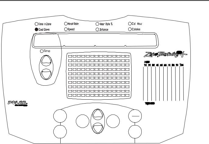
Upon entering the magnet test, the Cool Down LED is lit. The Message Center displays 3 different numeric values.
The left hand numeric display of 4 digits will show the desired position of the magnets. Numbers will range from 99256 on Version 1 Models and from 21-190 on Version 2 Models.
The right hand numeric display of three digits will show a number from 1 to 256. The number displayed is the actual position of the magnets.
Pressing the Level(Ù) button will activate the motor and move the magnets as to increase resistance. The center display will show the Resistance setting, the other 2 displays will show the associated desired and actual position of the magnets.
Pressing the Level(Ú) button will activate the motor and move the magnets as to decrease resistance. The center display will show the Resistance setting, the other 2 displays will show the associated desired and actual position of the magnets.
If the system determines that the motor is not responding properly, the display shows Motor Error and beeps to indicate a motor control error. Power will be removed from the motor in order to prevent damage. Power must be removed from the console to clear the error by unplugging the unit.
Press Enter to advance.
8
Life Fitness Models X5i, X5, X3i, and X3 Cross-Trainers
Diagnostic Mode For Deluxe Monitor
Diagnostic State 5 - A/D Test
X X X 


My |
|
Clear |
Workouts |
Workout |
Pause |
|
||
|
Enter |
|
|
Profiles |
|
|
|
|
Quick |
|
Cool |
Start |
|
Down |
Entering diagnostics State 5 indicates current motor position.
Press Enter to advance.
9
Life Fitness Models X5i, X5, X3i, and X3 Cross-Trainers
Diagnostic Mode For Deluxe Monitor
Diagnostic State 6 - Speed Reading Test
X 


My |
Clear |
|
Workouts |
||
Pause |
||
Workout |
||
Enter |
||
Profiles |
||
Quick |
Cool |
|
Start |
Down |
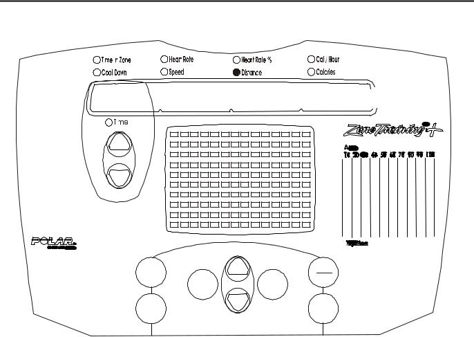
Upon entering, the SPEED LED will light. Diagnostic State 6 is used to test the OPTO or RPM Sensor function. To verify RPM signal, pedal and observe RPM value.
Note: On Version 2 Models, the Speed LED will flash each time a magnet passes the Reed Switch.
10
 Loading...