

FIT SERIES FIT-3
W/ LEG PRESS
Part # 7348201
Rev C.
ASSEMBLY INSTRUCTIONS
Revision:4/04/031

MAIN UNIT PARTS LIST
KEY
ACU04-1360
1
ACU04-1367
2
ACU04-1361
3
ACU04-1338
4
ACU04-1359
5
ACU04-1358
6
ACU04-1362
7
ACU04-1356
8
ACU04-1355
9
ACU04-1352
10
ACU04-1365
11
ACU04-1364
12
ACU04-1368
13
ACU04-1363
14
ACU04-1354
15
ACU02-1306
16
ACU04-1366
17
ACU02-1294
18
ACU02-1321
19
ACU04-1385
20
ACU02-1320
21
ACU05-0313
22
23
ACU02-1296
24
ACU01-2028
25
ACU05-0351
26
ACU06-0025
27
ACU06-0024
28
ACU02-1304
29
ACU02-0078
30
ACU05-0349
31
ACU06-0371
32
ACU06-0304
33
ACU01-2155
34
35
36
37
38
39
40
41
42
ACU72925
ACU06-0382
ACU10-0204ASY
ACU05-0356
ACU11-0067
ACU05-0212
ACU06-0388
ACU05-0348
ACU07-0157
PART #
DESCRIPTION
COUNTERBALANCE
FOOT REST
SEA T PAD SUPPORT
PRESS ARM
PIVOT ARM
MUL TI PRESS SEA T ADJUST
BACK P AD SUPPOR T
MUL TI PRESS FRAME
TOWER UPRIGHT
TOWER BASE
LA T/LOW BOOM
KNEE HOLD DOWN
LA T/LOW SEAT
LA T/LOW FRAME
SHROUD BRACKET
SHROUD SUPPORT BRACKET
SWIVEL PULLEY
MUL TI PRESS PLA TE
LA T/LOW PLATE
MUL TI-PRESS ADJUST PLA TE
LA T/LOW ADJUST PLA TE
1/2 X 3” SHOULDER BOL T
DUAL PULLEY PLATE
MUL TI PRESS SLIDE TUBE
PILLOW BLOCK
4-1/2” PULLEY
3-1/2” PULLEY
2-7/8 X 2-1/4” CABLE CLIP
3-1/2 X 1” CABLE CLIP
3/4 X 3-1/8” T APPED SHAFT
3” ACCORDIAN SLEEVE
3/4 X 2” WEIGHT ST ACK CUSHION
GUIDE ROD
WEIGHT PLA TE
2-3/8” OD PLASTIC W ASHER
HEAD PLA TE
PILLOW BLOCK SP ACER
WEIGHT ST ACK PIN
13/16” SHAFT COLLAR
1-1/4” SHAFT COLLAR
5-1/2” PIVOT SHAFT
LA T SEAT P AD
QTY
1
1
1
1
1
1
1
1
1
1
1
1
1
1
3
3
1
2
4
1
1
1
2
1
2
14
1
7
1
1
2
6
6
60
4
3
4
3
6
2
7
1
KEY
43
44
45
46
47
48
49
50
51
52
53
54
55
56
57
58
59
60
61
62
63
64
65
66
67
68
69
OR
70
71
72
73
74
75
76
77
78
79
80
81
82
83
PART #
ACU07-0156
ACU08-0077
ACU10-0215
ACU08-0085
ACU05-0350
ACU08-0078
ACUDA1C03804316NU
ACUDA1C03803216NU
ACUDA1C03804316NU
ACUDA1C03804316YU
ACUDA1C03805016NU
ACUDA1C03806116NU
ACUDA1C03806716NU
ACUDA1C03807016NU
ACUDA1C03807316NU
ACUDA1C03809016NU
ACUDA1C03809716NU
ACUDA1C03810616NU
ACUDA1C03816416NU
ACUDAEC03802516NB
ACUDAEC03807616NB
ACUDC1250100020B
ACUDB2E03807200U
ACUDC120010510U
ACU05-0310
ACU06-0357
ACU06-0357
ACU06-0357
ACU07-0158
ACU13-0122
ACU13-0123
ACU13-0121
ACU73086
ACU04-1353
ACU03-0340
ACU05-0193
ACUDI1080080U
ACU04-1386
ACU04-0622
ACU10-0205BLK
ACU10-0205BLK
ACU03-0536
DESCRIPTION
MUL TI PRESS BACK P AD
3/8 X 1” FLANGE SP ACER
5 X 8” ROLLER P AD
3/8 X 1/2” FLANGE SP ACER
3/8 X 1/2” SP ACER
3/8 X 3/4” FLANGE SP ACER
3/8 X 25mm BOL T
3/8 X 32mm BOL T
3/8 X 43mm BOL T
3/8 X 43mm BOL T W/LOCTITE
3/8 X 50mm BOL T
3/8 X 61mm BOL T
3/8 X 67mm BOL T
3/8 X 70mm BOL T
3/8 X 73mm BOL T
3/8 X 90mm BOL T
3/8 X 97mm BOL T
3/8 X 106mm BOL T
3/8 X 164mm BOL T
3/8 X 25mm BUTTON HEAD BOL T
3/8 X 76mm BUTTON HD BOL T
3/8” BLACK SAE W ASHER
3/8” LOW HEIGHT LOCK NUT
3/8” SAE W ASHER
3/8” RH WASHER
BLACK RH CAP
WHITE RH CAP
PLA TINUM RH CAP
MUL TI PRESS SEA T PAD
LA T CABLE
ROW CABLE
MUL TI-PRESS CABLE
WEIGHT ST ACK LABEL
STORAGE UPRIGHT
STORAGE PEG
12 LINK CHAIN
SNAP LINK
LA T BAR
LOW ROW BAR
MUL TI PRESS SHROUD
LA T SHROUD
5-1/2” T APPED PIVOT SHAFT
QTY
1
1
2
16
1
1
3
2
10
2
3
4
10
7
5
17
4
2
7
12
4
16
69
145
135
43
92
92
1
1
1
1
3
1
2
1
3
1
1
1
1
1
2
LEG PRESS PARTS LIST
KEY
PART #
ACU10-0205BLK
84
ACU04-1377
85
ACU04-1378
86
ACU04-1379
87
ACU04-1380
88
ACU04-1381
89
90
ACU07-0161
91
ACU07-0159
92
ACU13-0125
93
ACU06-0025
94
ACU02-1304
95
ACU08-0085
96
ACU08-0079
97
ACU05-0352
98
DESCRIPTION
LEG PRESS SHROUD
LEG PRESS FRAME
HANDLE
MAIN PIVOT ARM
SECONDARY PIVOT ARM
FOOT PLA TE
LEG PRESS PLACARD
LEG PRESS SEA T P AD
LEG PRESS BACK P AD
LEG PRESS CABLE
4-1/2” PULLEY
2-7/8 X 2-1/4” CABLE CLIP
3/8 X 1/2” FLANGE SP ACER
3/8 X 1-1/2” FLANGE SP ACER
3/4 X 4” PIVOT SHAFT
QTY
1
1
1
1
1
1
1
1
1
1
7
1
4
2
4
KEY
99
100
101
102
103
104
105
106
107
108
109
OR
110
111
112
PART #
ACUDA1C03804316NU
ACUDA1C03805016NU
ACUDA1C03806716NU
ACUDA1C03807016NU
ACUDA1C03807316NU
ACUDA1CO3811716NU
ACUDB2E03807200B
ACUDC120010510U
ACU05-0310
ACU06-0357
ACU06-0357
ACU06-0357
ACU04-1510
ACU13-0144
ACU04-1382
DESCRIPTION
3/8 X 43mm BOL T
3/8 X 50mm BOL T
3/8 X 67mm BOL T
3/8 X 70mm BOL T
3/8 X 73mm BOL T
3/8 X 117mm BOL T
3/8” LOW HEIGHT LOCK NUT
3/8” SAE WASHER
3/8” RH WASHER
BLACK RH CAP
WHITE RH CAP
PLA TINUM RH CAP
PULLEY BRACKET
FLOA TING PULLEY CABLE
BACK P AD SUPPORT
QTY
4
2
3
1
4
9
15
34
30
5
25
25
1
1
1
T ools Required for Assembly
* 9/16” wrench
* Ratchet with 9/16” socket
* Metric Allen wrench set
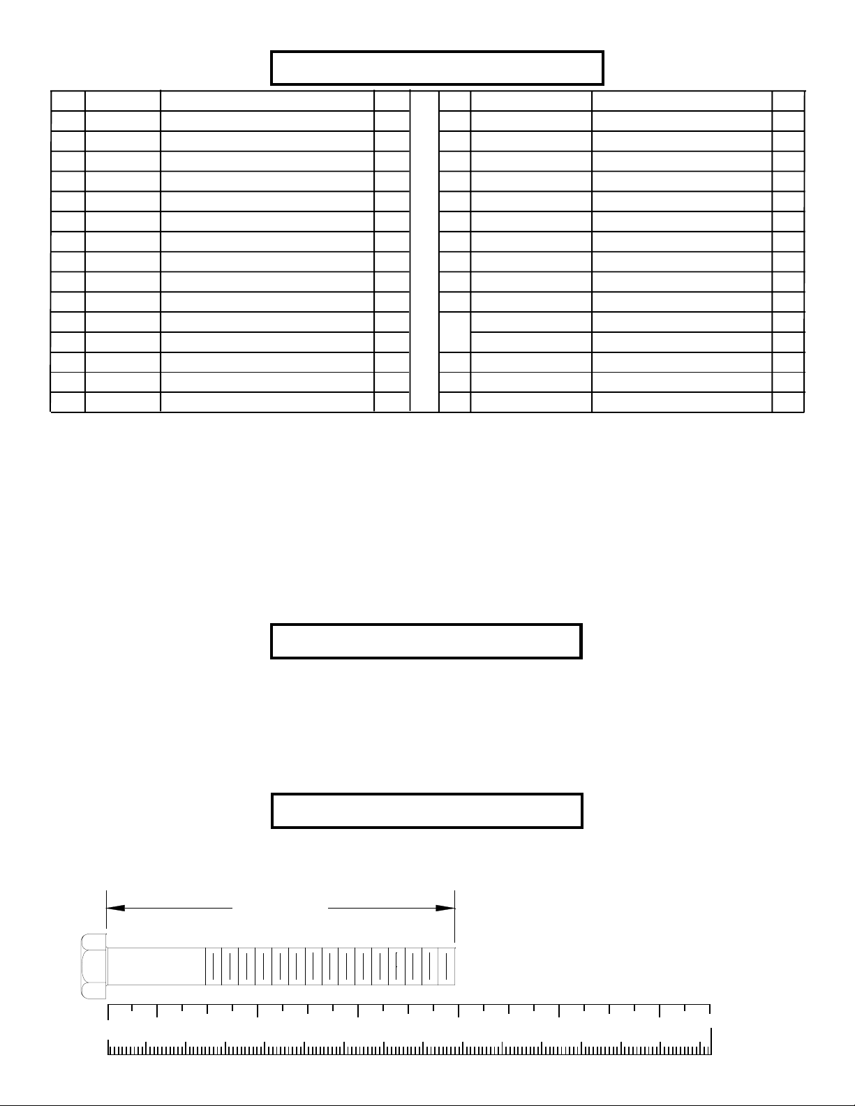
Bolt Length Ruler
NOTE: BOL T LENGTH IS MEASURED FROM THE UNDERSIDE OF THE HEAD OF THE BOLT .
BOLT LENGTH
0
1/2 1/2 1/2 1/2 1/2 1/2
10 20 30 40 50 60 70 80 90 100 110 120 130 140 150
1
23456
3
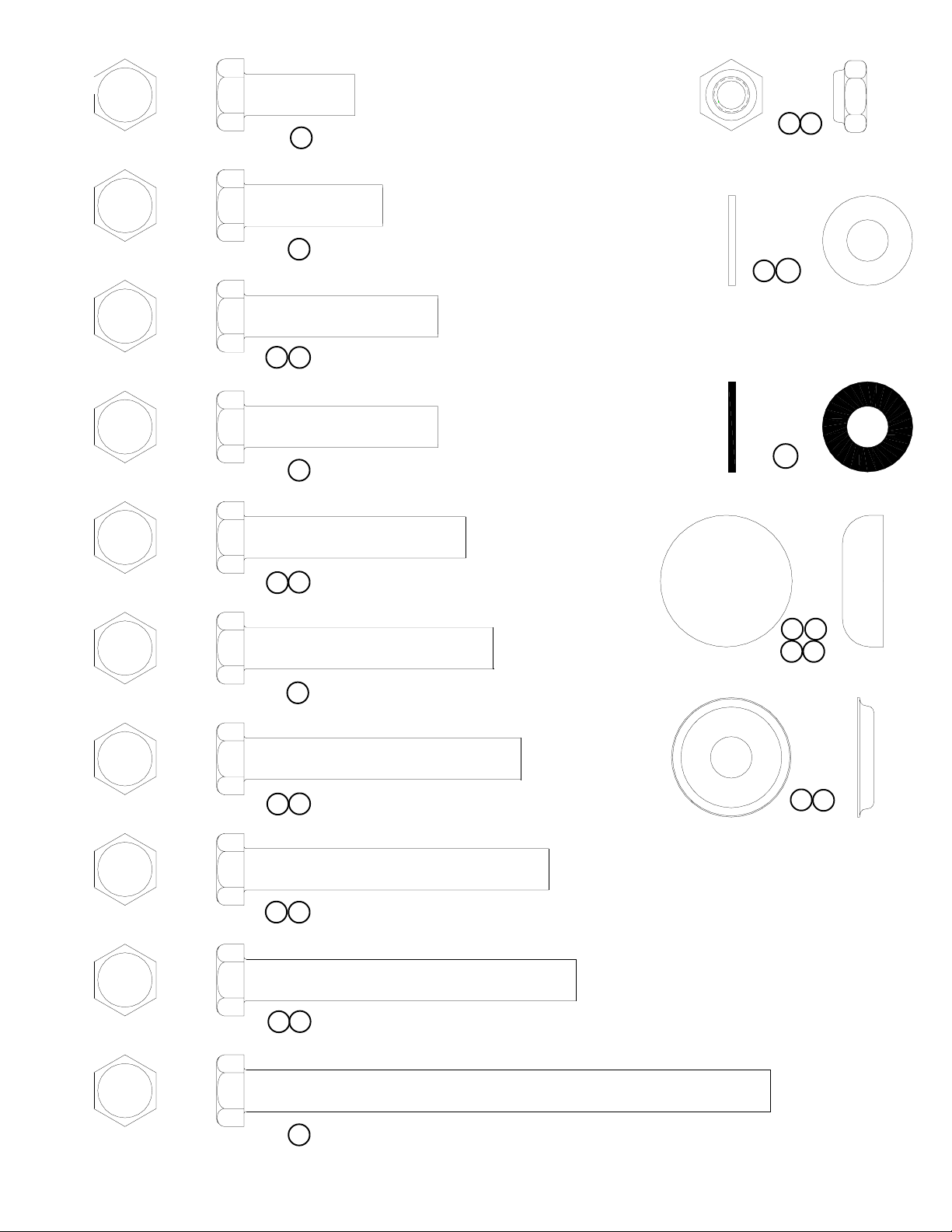
49 3/8 X 25mm BOL T
50 3/8 X 32mm BOL T
99 3/8 X 43mm BOL T
51
105
65
3/8” LOW
HEIGHT LOCK
NUT
106
66
3/8” SAE
WASHER
52 3/8 X 43mm BOL T W/NYLOCK
100 3/8 X 50mm BOL T
53
54 3/8 X 61mm BOL T
101 3/8 X 67mm BOL T
55
64
3/8” BLACK
SAE W ASHER
68
69
109
108
RH CAP
(WHITE/PLATINUM/BLACK)
107
67
RH
WASHER
102 3/8 X 70mm BOL T
56
103 3/8 X 73mm BOL T
57
104 3/8 X 117mm BOL T
4

58 3/8 X 90mm BOL T
59 3/8 X 97mm BOL T
60 3/8 X 106mm BOL T
61 3/8 X 164mm BOL T
62 3/8 X 25mm BUTTON HEAD BOL T
46
96
1/2”
FLANGE SP ACER
63 3/8 X 76mm BUTTON HEAD BOL T
22 1/2 X 3” SHOULDER BOLT
97
1-1/2”
FLANGE SP ACER
48
3/4”
FLANGE SP ACER
44
1”
FLANGE SP ACER
5
14
10
65
67
66
3/8 X 97mm 59
69
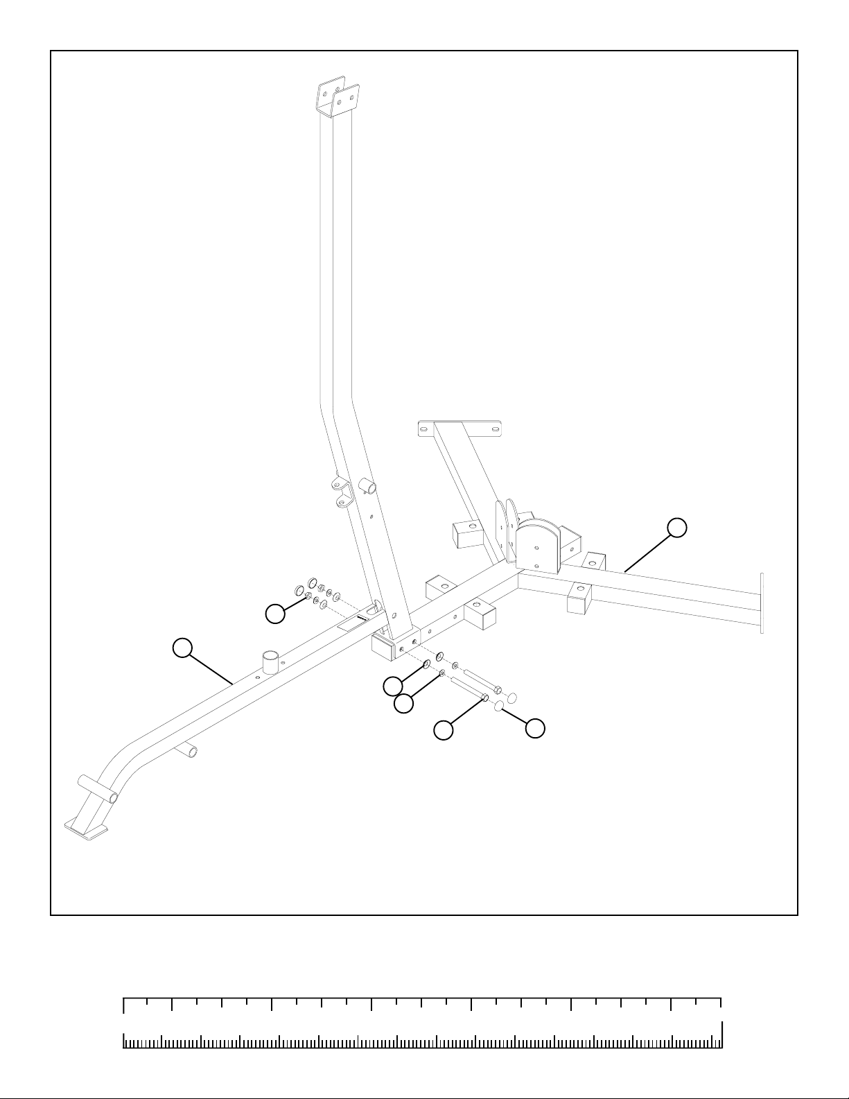
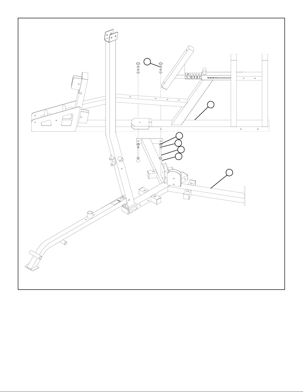
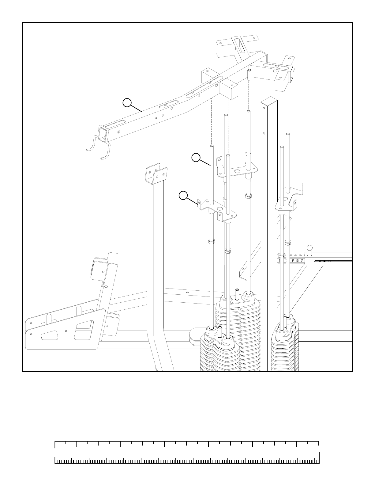
FIGURE 1
STEP 1:
• LOOSELY assemble the LA T/LOW FRAME (14) to the T OWER BASE (10) using four RH CAPS (69), two 3/8 X 97mm BOL TS (59),
four 3/8” SAE W ASHERS (66), four 3/8” RH W ASHERS (67) and two 3/8” LOW HEIGHT LOCK NUTS (65) as shown in FIGURE 1.
0
1/2 1/2 1/2 1/2 1/2 1/2
10 20 30 40 50 60 70 80 90 100 110 120 130 140 150
1
23456
6
65
85
67
66
104 3/8 X 117mm
69
10
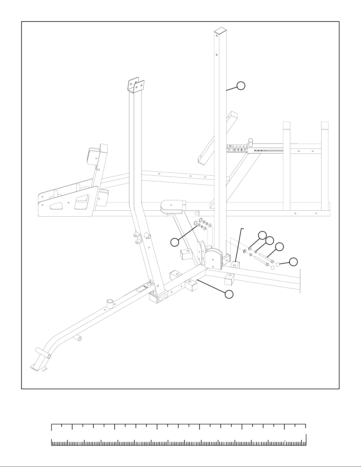
FIGURE 2
STEP 2:
• LOOSELY assemble the LEG PRESS FRAME (85) to the TOWER BASE (10) using four RH CAPS (69), two 3/8 X 1 17mm BOL TS
(104), four 3/8” SAE W ASHERS (66), four 3/8” RH WASHERS (67) and two 3/8” LOW HEIGHT LOCK NUTS (65) as shown in FIGURE 2. (NOTE: The two 3/8 X 117mm BOLTS (104) for this step are in the LEG PRESS hardwar e bag.)
7
65
9
REMOVE CAP BEFORE ASSEMBL Y!
67
66
59 3/8 X 97mm
69
10
FIGURE 3
STEP 3:
• LOOSELY assemble the TOWER UPRIGHT (9) to the TOWER BASE (10) using four RH CAPS (69), two 3/8 X 97mm BOL TS (59),
four 3/8” SAE W ASHERS (66), four 3/8” RH W ASHERS (67) and two 3/8” LOW HEIGHT LOCK NUTS (65) as shown in FIGURE 3.
(NOTE: REPLACE CAP AFTER ASSEMBL Y .)
0
1/2 1/2 1/2 1/2 1/2 1/2
10 20 30 40 50 60 70 80 90 100 110 120 130 140 150
1
23456
8
10
85
55 3/8 X 67mm
65
67
66
58 3/8 X 90mm
69
8
104 3/8 X 117mm
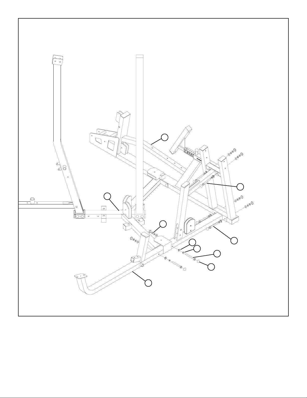
FIGURE 4
STEP 4:
• LOOSEL Y assemble the MUL TI PRESS FRAME (8) to the LEG PRESS FRAME (85) using eight RH CAPS (69), two 3/8 X 1 17mm BOL TS
(104), two 3/8 X 67mm BOL TS (55), eight 3/8” SAE WASHERS (66), eight 3/8” RH W ASHERS (67) and four 3/8” LOW HEIGHT LOCK
NUTS (65) as shown in FIGURE 4. (NOTE: The two 3/8 X 1 17mm BOL TS (104) for this step are in the LEG PRESS hardware bag.)
• LOOSELY assemble the MUL TI PRESS FRAME (8) to TOWER BASE (10) using four RH CAPS (69), two 3/8 X 90mm BOLTS (58),
four 3/8” SAE W ASHERS (66), four 3/8” RH W ASHERS (67) and two 3/8” LOW HEIGHT LOCK NUTS (65) as shown in FIGURE 4.
9
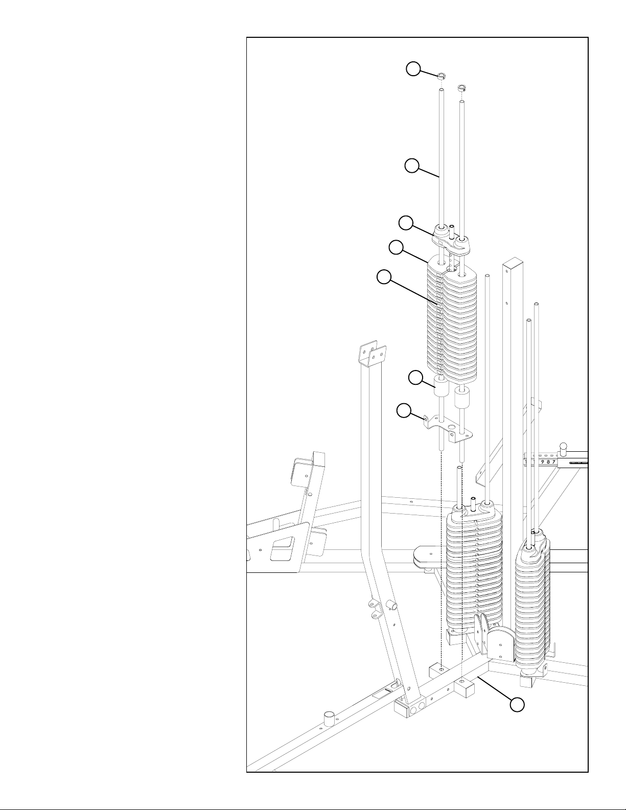
STEP 5:
• Insert two GUIDE RODS (33) through the
SHROUD SUPPORT BRACKET (16) and into
the TOWER BASE (10) as shown on FIGURE
5.
• (NOTE: Lubricate GUIDE RODS (33) with
silicon or teflon spray available at most
hardware stores.)
FIGURE 5
39
• Slide two 3/4 X 2” WEIGHT STACK CUSHIONS (32) down over the GUIDE RODS (33)
as shown in FIGURE 5.
• Using EXTREME CARE slide all twenty
WEIGHT PLATES (34) down over the GUIDE
RODS (33) on to the WEIGHT STACK CUSHIONS (32). Make sure that the WEIGHT
PLATES (34) are all facing as shown.
• Slide the HEAD PLATE ASSEMBLY (36) down
over the GUIDE RODS (33) onto the weight
stack as shown in FIGURE 5.
• Slide two 13/16” SHAFT COLLARS (39)
over the GUIDE RODS (33) as shown in
FIGURE 5.
• Apply WEIGHT STACK LABELS (74) to
WEIGHT PLA TES (34) and HEAD PLATE (36)
as shown in FIGURE 5. Begin with number one
at the HEAD PLATE (36) with larger numbers
in consecutive order towards bottom of weight
stack.
• Repeat STEP 5 to assemble two more weight
stacks to the TOWER BASE (10).
33
36
34
74
32
16
10
10
11
33
15
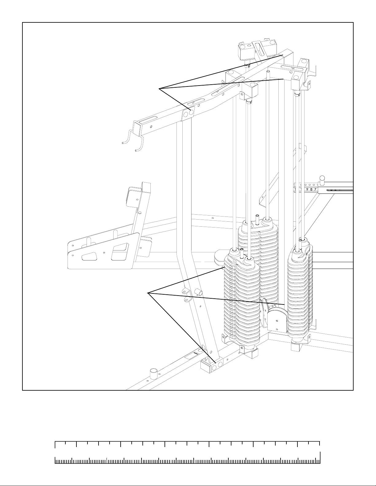
FIGURE 6
STEP 6:
• CAREFULLY slide three SHROUD BRACKETS (15) over all the GUIDE RODS (33) as shown in FIGURE 6.
• CAREFULLY assemble the LAT/LOW BOOM (11) over all the GUIDE RODS (33) as shown in FIGURE 6.
0
1/2 1/2 1/2 1/2 1/2 1/2
10 20 30 40 50 60 70 80 90 100 110 120 130 140 150
1
23456
11
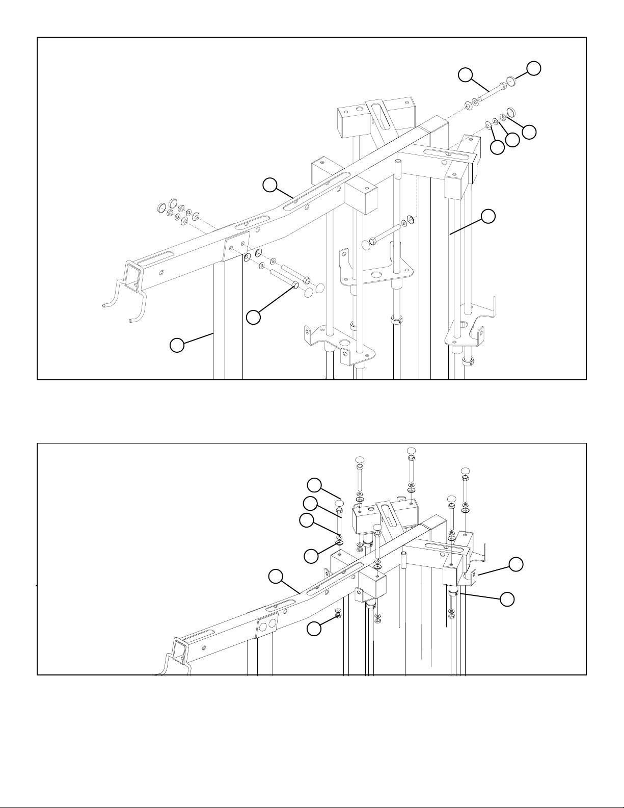
FIGURE 7
14
11
57 3/8 X 73mm
3/8 X 90mm 58
9
67
66
69
65
STEP 7:
• LOOSELY assemble the LAT/LOW BOOM (11) to the LAT/LOW FRAME (14) and the TOWER UPRIGHT (9) using seven RH
CAPS (69), two 3/8 X 73mm BOL TS (57), two 3/8 X 90mm BOL TS (58), seven 3/8” SAE WASHERS (66), seven 3/8” RH W ASHERS
(67) and three 3/8” LOW HEIGHT LOCK NUTS (65) as shown in FIGURE 7.
69
3/8 X 90mm 58
66
67
11
65
15
39
TIGHTEN!
FIGURE 8
STEP 8:
• SECUREL Y assemble the three SHROUD BRACKETS (15) to the LAT/LOW BOOM (11) using six RH CAPS (69), six 3/8 X 90mm
BOL TS (58), twelve 3/8” SAE WASHERS (66), six 3/8” RH W ASHERS (67) and six 3/8” LOW HEIGHT LOCK NUTS (65) as shown
in FIGURE 8. (NOTE: Use RH W ASHERS and RH CAPS on top only .)
• Slide the 13/16” SHAFT COLLARS (39) up against the SHROUD BRACKETS (15) and SECURELY tighten the set screws on
the SHAFT COLLARS (39). See FIGURE 8.
12
LUBRICATION NOTE:
When finished assembling the W eight Stack, open the lube Pack provided
with this unit and apply a thin film of Lubricant around the first 2 to 3
inches of each Guide Rod above the Head Plate Assembly . After the
cables are installed, use of the machine will spread the lubricant over the
length of the Guide Rods and into the Head Plate
Assemblies bushings
TIGHTEN!
TIGHTEN!
FIGURE 9
STEP 9:
• Securely tighten all loose frame connections made to this point, then proceed to snap RH CAPS
(69) over the RH WASHERS (67) on all tightened connections.
0
1/2 1/2 1/2 1/2 1/2 1/2
10 20 30 40 50 60 70 80 90 100 110 120 130 140 150
1
23456
13

65
13
14
41
FIGURE 10
19
67
66
61 3/8 X 164mm
68 BLACK
STEP 10:
• Insert four 5-1/2” PIVOT SHAFTS (41) into the LAT/LOW FRAME (14) and the LA T/LOW SEAT (13) as shown in FIGURE 10.
• SECURELY assemble four LA T/LOW PLATES (19) to the LA T/LOW SEA T (13) and to the LAT/LOW FRAME (14) using eight
BLACK RH CAPS (68), four 3/8 X 164mm BOL TS (61), eight 3/8” SAE WASHERS (66), eight 3/8” RH W ASHERS (67) and four 3/8”
LOW HEIGHT LOCK NUTS (65) as shown in FIGURE 10.
69
3/8 X 67mm 55
14
2
67
66
FIGURE 11
65
STEP 11:
• SECUREL Y assemble FOOT REST (2) to the LA T/LOW FRAME (14) using four RH CAPS (69), two 3/8 X 67mm BOLTS (55), four 3/8”
SAE W ASHERS (66), four 3/8” RH W ASHERS (67) and two 3/8” LOW HEIGHT LOCK NUTS (65) as shown in FIGURE 11.
14

42
13
67
3/8 X 50mm 53
BLACK 68
66
FIGURE 12
STEP 12:
• SECUREL Y assemble LAT SEA T PAD (42) to the LA T/LOW SEA T (13) using two BLACK RH CAPS (68), two 3/8 X 50mm BOL TS (53),
two 3/8” SAE WASHERS (66) and two 3/8” RH W ASHERS (67) as shown in FIGURE 12.
FIGURE 13
1/2 X 3” 22
17
66
67
14
69
65
STEP 13:
• Assemble the SWIVEL PULLEY (17) to the LAT/LOW FRAME (14) using one 1/2 X 3” SHOULDER BOLT (22), one 3/8” RH
WASHER (67), one 3/8” SAE W ASHER (66) one 3/8” LOW HEIGHT LOCK NUT (65) and one RH CAP (69) as shown in FIGURE
13. (NOTE: Tighten connection enough to remove play, yet allowing SWIVEL PULLEY (17) to rotate freely.)
0
1/2 1/2 1/2 1/2 1/2 1/2
10 20 30 40 50 60 70 80 90 100 110 120 130 140 150
1
23456
15

68
69
65
3/8 X 67mm 55
14
30
47
21
67
66
53 3/8 X 50mm
68 BLACK
FIGURE 14
STEP 14:
• SECURELY assemble the LAT/LOW ADJUST PLATE (21) to the LAT/LOW FRAME (14) using two BLACK RH CAPS (68),
two RH CAPS (69), two 3/8 X 67mm BOL TS (55), four 3/8” SAE WASHERS (66), four 3/8” RH W ASHERS (67) and two 3/8” LOW
HEIGHT LOCK NUTS (65) as shown in FIGURE 14.
• Assemble the 3/4 X 3-1/8” TAPPED SHAFT (30) to the LAT/LOW ADJUST PLATE (21) using two BLACK RH CAPS (68), one
3/8 X 50mm BOL T (53), two 3/8” SAE WASHERS (66), two 3/8” RH WASHERS (67), one 3/8 X 1/2” SPACER (47) and one 3/8” LOW
HEIGHT LOCK NUT (65) as shown in FIGURE 14. (NOTE: T ighten connection enough to remove play, yet allowing T APPED
SHAFT to rotate freely .)
FIGURE 15
69
65
67
66
71
11
69
28
3/8 X 70mm 56
BLACK 68
2646
68
BLACK
51 3/8 X 43mm
69
23
STEP 15:
• Route the LAT CABLE (71) through the LAT/LOW BOOM (11) and assemble two 4-1/2” PULLEYS (26) to the BOOM (11) using two RH CAPS (69), two BLACK RH CAPS (68), two 3/8 X 70mm BOL TS (56), four 3/8” SAE WASHERS (66), four 3/8” RH
W ASHERS (67), two 2-7/8” X 2-1/4” CABLE CLIPS (28), four 3/8 X 1/2” FLANGE SP ACERS (46) and two 3/8” LOW HEIGHT LOCK
NUTS (65) as shown in FIGURE 15.
• Route the LAT CABLE (71) around one 4-1/2” PULLEY (26) and assemble the PULLEY to two DUAL PULLEY PLATES (23)
using two RH CAPS (69), one 3/8 X 43mm BOL T (51), two 3/8” SAE WASHERS (66), two 3/8” RH W ASHERS (67) and one 3/8”
LOW HEIGHT LOCK NUT (65) as shown in FIGURE 15.
16

69
65
26
66
67
46
56 3/8 X 70mm
28
11
68 BLACK
71
36
38
FIGURE 16
STEP 16:
• Route the LAT CABLE (71) through the LAT/LOW BOOM (11) and assemble two 4-1/2” PULLEYS (26) to the BOOM (11) using two BLACK RH CAPS (68), two RH CAPS (69), two 3/8 X 70mm BOL TS (56), four 3/8” SAE WASHERS (66), four 3/8” RH
W ASHERS (67), two 2-7/8 X 2-1/4” CABLE CLIPS (28), four 3/8 X 1/2” FLANGE SP ACERS (46) and two 3/8” LOW HEIGHT LOCK
NUTS (65) as shown in FIGURE 16.
• Slide one WEIGHT STACK PIN (38) over the stem on the HEAD PLATE (36) as shown in FIGURE 16.
• Screw the threaded end of the LAT CABLE (71) all the way onto the end of the stem on the HEAD PLATE (36) and tighten jam
nut securely. See FIGURE 16.
0
1/2 1/2 1/2 1/2 1/2 1/2
10 20 30 40 50 60 70 80 90 100 110 120 130 140 150
1
23456
17

72
17
27
26
69
65
14
51 3/8 X 43mm
46
28
68 BLACK
67
56 3/8 X 70mm
66
68 BLACK
FIGURE 17
STEP 17:
• Route the ROW CABLE (72) around one 4-1/2” PULLEY (26) and assemble the 4-1/2” PULLEY and one 3-1/2” PULLEY (27)
to the SWIVEL PULLEY (17) using six BLACK RH CAPS (68), three 3/8 X 43mm BOL TS (51), six 3/8” SAE WASHERS (66), six 3/8”
RH WASHERS (67) and three 3/8” LOW HEIGHT LOCK NUTS (65) as shown in FIGURE 17.
• Route the ROW CABLE (72) through the LAT/LOW FRAME (14) and assemble one 4-1/2” PULLEY (26) using one RH CAP
(69), one BLACK RH CAP (68), one 3/8 X 70mm BOL T (56), two 3/8” SAE W ASHERS (66), two 3/8” RH W ASHERS (67), one 2-7/8
X 2-1/4” CABLE CLIP (28), two 3/8 X 1/2” FLANGE SP ACERS (46) and one 3/8” LOW HEIGHT LOCK NUT (65) as shown in FIGURE 17.
18

FIGURE 18
41
65
72
30
23
67
26
51 3/8 X 43mm
66
69
14
STEP 18:
• Route the ROW CABLE (72) around one 4-1/2” PULLEY (26) and assemble the PULLEY to the bottom holes of the DUAL
PULLEY PLA TES (23) using two RH CAPS (69), one 3/8 X 43mm BOL T (51), two 3/8” SAE W ASHERS (66), two 3/8” RH W ASHERS (67)
and one 3/8” LOW HEIGHT LOCK NUT (65) as shown in FIGURE 18.
• Screw the threaded end of the ROW CABLE (72) all the way onto the end of the 3/4 X 3-1/8” TAPPED SHAFT (30) and tighten
jam nut securely. See FIGURE 18.
• Insert one 5-1/2” PIVOT SHAFT (41) into the LAT/LOW ROW FRAME (14) as shown in FIGURE 18.
0
1/2 1/2 1/2 1/2 1/2 1/2
10 20 30 40 50 60 70 80 90 100 110 120 130 140 150
1
23456
19

12
65
14
67
66
45
35
3/8 X 164mm 61
40
69
FIGURE 19
STEP 19:
• SECURELY assemble the KNEE HOLD DOWN (12) to the LA T/LOW FRAME (14) using two RH CAPS (69), one 3/8 X 164mm BOL T
(61), two 3/8” SAE W ASHERS (66), two 3/8” RH W ASHERS (67) and one 3/8” LOW HEIGHT LOCK NUT (65) as shown in FIGURE 19.
• Assemble two ROLLER PADS (45) and four 2-3/8” OD PLASTIC WASHERS (35) to the KNEE HOLD DOWN (12) using two
1-1/4” SHAFT COLLARS (40) as shown in FIGURE 19.
20

8
24
6
SPRING PIN
FIGURE 20
STEP 20:
• Pull back on the SPRING PIN and slide the MUL TI PRESS SEAT ADJUST (6) over the MULTI PRESS SLIDE TUBE (24) as shown
in FIGURE 20.
• Slide the end of the MULTI PRESS SLIDE TUBE (24) over the MULTI PRESS FRAME (8) as shown in FIGURE 20.
8
3/8 X 25mm 49
54 3/8 X 61mm
69
55 3/8 X 67mm
66
67
24
65
FIGURE 21
STEP 21:
• SECURELY assemble the MULTI PRESS SLIDE TUBE (24) to the MULTI PRESS FRAME (8) using seven RH CAPS (69), two
3/8 X 67mm BOL TS (55), one 3/8 X 61mm BOL T (54), one 3/8 X 25mm BOLT (49), seven 3/8” SAE W ASHERS (66), seven 3/8” RH
W ASHERS (67) and three 3/8” LOW HEIGHT LOCK NUTS (65) as shown in FIGURE 21.
0
1/2 1/2 1/2 1/2 1/2 1/2
10 20 30 40 50 60 70 80 90 100 110 120 130 140 150
1
23456
21

41
7
41
3
FIGURE 22
8
STEP 22:
• Insert one 5-1/2” PIVOT SHAFT (41) into the MULTI PRESS FRAME (8) and one 5-1/2” PIVOT SHAFT (41) into the BACK P AD
SUPPORT (7) as shown in FIGURE 22.
7
8
18
67
65
66
68 BLACK
6
3
68 BLACK
3/8 X 164mm 61
60 3/8 X 106mm
FIGURE 23
STEP 23:
• SECURELY assemble the BACK P AD SUPPORT (7) to the MULTI PRESS SEA T ADJUST (6) using two BLACK RH CAPS (68),
one 3/8 X 106mm BOL T (60), two 3/8” SAE WASHERS (66), two 3/8” RH W ASHERS (67) and one 3/8” LOW HEIGHT LOCK NUT (65)
as shown in FIGURE 23. (NOTE: TIghten connections enough to remove slop, yet allow part to rotate fr eely.)
• SECURELY assemble two MULTI PRESS PLATES (18) to the BACK PAD SUPPORT (7) and to the MULTI PRESS FRAME (8)
using four BLACK RH CAPS (68), two 3/8 X 164mm BOL TS (61), four 3/8” SAE WASHERS (66), four 3/8” RH W ASHERS (67) and two
3/8” LOW HEIGHT LOCK NUTS (65) as shown in FIGURE 23.
• SECURELY assemble the SEAT PAD SUPPORT (3) to the MULTI PRESS SEA T ADJUST (6) using two BLACK RH CAPS (68),
one 3/8 X 106mm BOL T (60), two 3/8” SAE WASHERS (66), two 3/8” RH W ASHERS (67) and one 3/8” LOW HEIGHT LOCK NUT (65)
as shown in FIGURE 23. (NOTE: TIghten connections enough to remove slop, yet allow part to rotate fr eely.)
22

3/8 X 73mm 57
7
FIGURE 24
43
STEP 24:
• SECURELY assemble the MULTI PRESS BACK PAD
(43) to the BACK PAD SUPPORT (7) using two
BLACK RH CAPS (68), two 3/8 X 73mm BOL TS (57),
two 3/8” SAE WASHERS (66), two 3/8” RH W ASHERS
(67) as shown in FIGURE 24.
• SECURELY assemble the MUL TI PRESS SEAT P A D
(70) to the SEAT PAD SUPPORT (3) using two
BLACK RH CAPS (68), two 3/8 X 32mm BOL TS (50),
two 3/8” SAE WASHERS (66), two 3/8” RH W ASHERS
(67) as shown in FIGURE 24.
68
BLACK
67
66
3/8 X 32mm 50
STEP 25:
• Slide two 3” ACCORIDIAN SLEEVES
(31) over the shafts on the PIVOT ARM
(5) as shown in FIGURE 25.
• Slide two PILLOW BLOCKS (25) over
the shafts on the PIVOT ARM (5) as
shown in FIGURE 25.
70
3
BLACK 64
31
37
25
• Assemble four 3/8 X 76mm BUTT ON
HEAD BOL TS (63), four 3/8” BLACK
SAE WASHERS (64) and four PILLOW
BLOCK SP ACERS (37) to the the
PILLOW BLOCKS (25)
FIGURE 25.
0
10 20 30 40 50 60 70 80 90 100 110 120 130 140 150
as shown in
1/2 1/2 1/2 1/2 1/2 1/2
1
63 3/8 X 76mm
BUTTON HEAD
5
FIGURE 25
23456
23

25
TIGHTEN!
69
65
67
66
92
5
FIGURE 26
STEP 26:
• SECUREL Y assemble the PIVOT ARM (5) to the LEG CURL/EXT FRAME (92) using four previously inserted 3/8 X 76mm BUTTON
HEAD BOL TS (63), four RH W ASHERS (67), four 3/8” SAE W ASHERS (66), four 3/8” LOW HEIGHT LOCK NUTS (65) and four RH
CAPS (69) as shown in FIGURE 26.
• IMPORTANT! When PIVOT ARM (5) is centered and level in the PILLOW BLOCKS (25), tighten the PILLOW BLOCK set
screws.
83
69
44
68 BLACK
5
65
66
67
20
3/8 X 73mm 57
69
48
58 3/8 X 90mm
68 BLACK
73
55 3/8 X67mm
FIGURE 27
STEP 27:
• SECURELY assemble the MULTI PRESS ADJUST PLATE (20) to the PIVOT ARM (5) using three RH CAPS (69), three
BLACK RH CAPS (68), one 3/8 X 67mm BOL TS (55), one 3/8 X 73mm BOL T (57), one 3/8 X 90mm BOL T (58), six 3/8” SAE W ASHERS (66), six 3/8” RH W ASHERS (67), one 3/8 X 3/4” FLANGE SPACER (48), one 3/8 X 1” FLANGE SP ACER (44), one MUL TI
PRESS CABLE (73) and three 3/8” LOW HEIGHT LOCK NUTS (65) as shown in FIGURE 27. (NOTE: Assemble the MUL TI PRESS
CABLE to the second set of holes.)
• Insert one 5-1/2” TAPPED PIVOT SHAFT (83) into the PIVOT ARM (5).
24

69
1
65
5
67
66
3/8 X 61m 54
3/8 X 43mm 52
W/LOCTITE
4
FIGURE 28
STEP 28:
• SECURELY assemble the PRESS ARM (4) to the PIVOT ARM (5) using two RH CAPS (69), two 3/8 X 43mm BOL TS W/LOCTITE
(52), two 3/8” SAE WASHERS (66) and two 3/8” RH W ASHERS (67) as shown in FIGURE 28.
• SECUREL Y assemble the COUNTERBALANCE (1) to the PIVOT ARM (5) using four RH CAPS (69), two 3/8 X 61mm BOL TS (54), four
3/8” SAE W ASHERS (66), four 3/8” RH W ASHERS (67) and two 3/8” LOW HEIGHT LOCK NUTS (65) as shown in FIGURE 28.
0
1/2 1/2 1/2 1/2 1/2 1/2
10 20 30 40 50 60 70 80 90 100 110 120 130 140 150
1
23456
25

28
68 BLACK
3/8 X 70mm 56
FIGURE 29
69
26
5
4
73
65
8
46
3/8 X 67mm 55
69
67
66
54 3/8 X 61mm
26
STEP 29:
• Route the MULTI PRESS CABLE (73) through the MULTI PRESS FRAME (8) and assemble one 4-1/2” PULLEY (26) to the
FRAME (8) using four RH CAPS (69), one 3/8 X 67mm BOL T (55), one 3/8 X 61mm BOLT (54), four 3/8” SAE W ASHERS (66), four
3/8” RH W ASHERS (67), two 3/8 X 1/2” FLANGE SPACERS (46) and two 3/8” LOW HEIGHT LOCK NUTS (65) as shown in FIGURE 29.
• Route the MULTI PRESS CABLE (73) through the MULTI PRESS FRAME (8) and PIVOT ARM (5) and assemble one 4-1/2”
PULLEY (26) to the PIVOT ARM (5) using one BLACK RH CAP (68), one RH CAP (69), one 3/8 X 70mm BOLT (56), two 3/8” SAE
W ASHERS (66), two 3/8” RH WASHERS (67), one 2-7/8” X 2-1/4” CABLE CLIP (28), two 3/8 X 1/2” FLANGE SP ACERS (46) and one
3/8” LOW HEIGHT LOCK NUT (65) as shown in FIGURE 29.
26

FIGURE 30
8
3/8 X 43mm 51
26
26
73
66
29
67
65
68 BLACK
69
69
51 3/8 X 43mm
STEP 30:
• Route the MULTI PRESS CABLE (73) through the bracket on the MULTI PRESS FRAME (8) and assemble one 4-1/2” PULLEY
(26) to the FRAME (8) using four RH CAPS (69), two 3/8 X 43mm BOL TS (51), four 3/8” SAE WASHERS (66), four 3/8” RH W ASHERS (67) and two 3/8” LOW HEIGHT LOCK NUTS (65) as shown in FIGURE 30.
• Route the MULTI PRESS CABLE (73) under the bracket on the MULTI PRESS FRAME (8) and assemble one 4-1/2” PULLEY
(26) to the FRAME (8) using one BLACK RH CAP (68), one RH CAP (69), one 3/8 X 43mm BOL T (51), two 3/8” SAE WASHERS
(66), two 3/8” RH WASHERS (67), one 3-1/2 X 1” CABLE CLIP (29) and one 3/8” LOW HEIGHT LOCK NUT (65) as shown in FIGURE 30.
0
1/2 1/2 1/2 1/2 1/2 1/2
10 20 30 40 50 60 70 80 90 100 110 120 130 140 150
1
23456
27

FIGURE 31
73
65
26
10
66
51 3/8 X 43mm
STEP 31:
• Route the MULTI PRESS CABLE (73) under the weight stack and through the bracket on the TOWER BASE (10) and assemble
one 4-1/2” PULLEY (26) to the T OWER BASE (10) using two 3/8 X 43mm BOL TS (51), four 3/8” SAE WASHERS (66) and two 3/8”
LOW HEIGHT LOCK NUTS (65) as shown in FIGURE 31.
28

FIGURE 32
3/8 X 70mm 56
28
68
BLACK
26
69
66
65
67
46
11
73
38
36
STEP 32:
• Route the MULTI PRESS CABLE (73) through the LAT/LOW BOOM (11) and assemble one 4-1/2” PULLEY (26) to the BOOM
(11) using one BLACK RH CAP (68), one RH CAP (69), one 3/8 X 70mm BOLT (56), two 3/8” SAE W ASHERS (66), two 3/8” RH
W ASHERS (67), one 2-7/8” X 2-1/4” CABLE CLIP (28), two 3/8 X 1/2” FLANGE SP ACERS (46) and one 3/8” LOW HEIGHT LOCK
NUT (65) as shown in FIGURE 32.
• Slide one WEIGHT STACK PIN (38) over the stem on the HEAD PLATE (36) as shown in FIGURE 32.
• Screw the threaded end of the MULTI PRESS CABLE (73) all the way onto the end of the stem on the HEAD PLATE (36) and
tighten jam nut securely. See FIGURE 32.
0
1/2 1/2 1/2 1/2 1/2 1/2
10 20 30 40 50 60 70 80 90 100 110 120 130 140 150
1
23456
29

66
49 3/8 X 25mm
76
75
65
67
69
67
66
3/8 X 90mm 58
10
69
FIGURE 33
STEP 33:
• SECURELY assemble the STORAGE UPRIGHT (75) to the TOWER BASE (10) using four RH CAPS (69), two 3/8 X 90mm BOL TS
(58), four 3/8” SAE WASHERS (66), four 3/8” RH W ASHERS (67) and two 3/8” LOW HEIGHT LOCK NUTS (65) as shown in
FIGURE 33.
• SECUREL Y assemble the ST ORAGE PEGS (76) to the STORAGE UPRIGHT (75) using two RH CAPS (69), two 3/8 X 25mm BOL TS
(49), two 3/8” SAE W ASHERS (66) and two 3/8” RH W ASHERS (67) as shown in FIGURE 33.
• Please refer to the LEG PRESS PARTS LIST to complete the
assembly of the LEG PRESS.
30

STEP 34:
• Slide one WEIGHT STACK SELECTOR PIN (38)
over the shaft on the HEAD PLATE (36) as shown
in FIGURE 34.
• Screw the threaded end of the FLOATING PULLEY CABLE (111) all the way onto the end of the
shaft on the HEAD PLATE (36) and tighten jam
nut securely. See FIGURE 34.
• Route the FLOATING PULLEY CABLE (1 11)
through the LAT/LOW ROW BOOM (11) and
assemble one 4-1/2” PULLEY (94) to the
BOOM (11) using one RH CAP (109), one
BLACK RH CAP (108), one 3/8 X 70mm BOL T
(102), two 3/8” SAE W ASHERS (106), two 3/8”
RH W ASHERS (107), one 2-7/8 X 2-1/4” CABLE
CLIP (95), two 3/8 X 1/2” FLANGE SP ACERS (96)
and one 3/8” LOW HEIGHT LOCK NUT (105) as
shown in FIGURE 34.
FIGURE 34
3/8 X 70mm 102
95
108 BLACK
3/8 X 43mm 99
BLACK 108
11
94
111
110
94
105
109
106
107
96
108
BLACK
• Route the FLOATING PULLEY CABLE (1 11)
around one 4-1/2” PULLEY (94) and assemble
the PULLEY (94) to the PULLEY BRACKET
(110) using two BLACK RH CAPS (108), one
3/8 X 43mm BOL T (99), two 3/8” SAE WASHERS
(106), two 3/8” RH WASHERS (107) and one 3/8”
LOW HEIGHT LOCK NUT (105) as shown in FIGURE 34.
38
36
1/2 1/2 1/2 1/2 1/2 1/2
0
1
2
345
31
6

FIGURE 35
11
111
STEP 35:
• Screw the threaded end of the FLOATING PULLEY CABLE (111) all the way onto the end of the shaft on the LAT/LOW ROW
BOOM (11) and tighten jam nut securely. See FIGURE 35.
0
1/2 1/2 1/2 1/2 1/2 1/2
10 20 30 40 50 60 70 80 90 100 110 120 130 140 150
1
23456
32

FIGURE 36
3/8 X 67mm 101
86
85
109
106
107
105
STEP 36:
• SECURELY assemble the HANDLE (86) to the LEG PRESS FRAME (85) using four RH CAPS (109), two 3/8 X 67mm BOL TS (101),
four 3/8” SAE WASHERS (106), four 3/8” RH W ASHERS (107) and two 3/8” LOW HEIGHT LOCK NUTS (105) as shown in FIGURE
36.
FIGURE 37
STEP 37:
109
88
105
106
98
107
87
1”
3/8 X 117mm 104
85
13”
• Assemble four 3/4 X 4” PIVOT SHAFTS (98) to the MAIN & SECONDARY PIVOT ARMS (87 & 88) as shown in FIGURE 37.
• SECURELY assemble the MAIN & SECONDARY PIVOT ARMS (87 & 88) to the LEG PRESS FRAME (85) using four RH
CAPS (109), two 3/8 X 117mm BOL TS (104), four 3/8” SAE WASHERS (106), four 3/8” RH WASHERS (107) and two 3/8” LOW
HEIGHT LOCK NUTS (105) as shown in FIGURE 37. (NOTE: Make sure the MAIN PIVOT ARM is assembled as shown.)
33

89
85
105
87
88
107
106
FIGURE 38
3/8 X 117mm 104
109
STEP 38:
• SECURELY assemble the FOOT PLATE (89) to the MAIN & SECONDARY PIVOT ARMS (87 & 88) using four RH CAPS
(109), two 3/8 X 117mm BOL TS (104), four 3/8” SAE W ASHERS (106), four 3/8” RH WASHERS (107), and two 3/8” LOW HEIGHT
LOCK NUTS (105) as shown in FIGURE 38.
103 3/8 X 73mm
106
107
92
112
108 BLACK
FIGURE 39
STEP 39:
• SECURELY assemble the LEG PRESS BACK PAD (92) to the BACK PAD SUPPORT (112) using two BLACK RH CAPS (108),
two 3/8 X 73mm BOL TS (103), two 3/8” SAE WASHERS (106) and two 3/8” RH W ASHERS (107) as shown in FIGURE 39.
34

91
85
107
106
103 3/8 X 73mm
109
FIGURE 40
STEP 40:
• SECUREL Y assemble theLEG PRESS SEA T P AD (91) to the LEG PRESS FRAME (85) using two RH CAPS (109), two 3/8 X 73mm BOL TS
(103),two 3/8” SAE W ASHERS (106) and two 3/8” RH W ASHERS (107) as shown in FIGURE 40.
105
87
FIGURE 41
96
107
94
85
106
101 3/8 X 67mm
93
100 3/8 X 50mm
109
STEP 41:
• Route the LEG PRESS CABLE (93) through the MAIN PIVOT ARM (87) and assemble one 4-1/2” PULLEY (94) to the MAIN
PIVOT ARM (87) using two RH CAPS (109), one 3/8 X 67mm BOL T (101), two 3/8 X 1/2” FLANGE SP ACERS (96), two 3/8” SAE
W ASHERS (106), two 3/8” RH W ASHERS (107) and one 3/8” LOW HEIGHT LOCK NUT (105) as shown in FIGURE 41.
• Route the LEG PRESS CABLE (93) between the upper bracket and through the tube on the LEG PRESS FRAME (85) and assemble
one 4-1/2” PULLEY (94) to the FRAME (85) using two RH CAPS (109), one 3/8 X 50mm BOL T (100), two 3/8” SAE W ASHERS (106),
two 3/8” RH WASHERS (107) and one 3/8” LOW HEIGHT LOCK NUT (105) as shown in FIGURE 41.
• Route the LEG PRESS CABLE (93) between the lower BRACKETS on the LEG PRESS FRAME (85) and assemble one 4-1/2”
PULLEY (94) to the FRAME (85) using two RH CAPS (109), one 3/8 X 50mm BOL T (100), two 3/8” SAE W ASHERS (106), two 3/8” RH
W ASHERS (107) and one 3/8” LOW HEIGHT LOCK NUT (105) as shown in FIGURE 41.
35

85
109
93
105
97
107
106
104 3/8 X 117mm
87
FIGURE 42
STEP 42:
• Assemble the swivel end of the LEG PRESS CABLE (93) to the LEG PRESS FRAME (85) using two RH CAPS (109), one 3/8 X 1 17mm
BOL T (104), two 3/8 X 1-1/2” FLANGE SP ACERS (97), two 3/8” SAE W ASHERS (106), two 3/8” RH W ASHERS (107) and one 3/8” LOW
HEIGHT LOCK NUT (105) as shown in FIGURE 42.
109
85
94
106
107
105
99 3/8 X 43mm
93
FIGURE 43
STEP 43:
• Route the LEG PRESS CABLE (93) through the bracket on the LEG PRESS FRAME (85) and assemble one 4-1/2” PULLEY
(94) to the bracket on the FRAME (85) using two RH CAPS (109), one 3/8 X 43mm BOL T (99), two 3/8” SAE W ASHERS (106), two
3/8” RH WASHERS (107) and one 3/8” LOW HEIGHT LOCK NUT (105) as shown in FIGURE 43.
0
1/2 1/2 1/2 1/2 1/2 1/2
10 20 30 40 50 60 70 80 90 100 110 120 130 140 150
1
23456
36

94
10
106
99 3/8 X 43mm
93
105
FIGURE 44
STEP 44:
• Route the LEG PRESS CABLE (93) under the weight stack and through the bracket on the TOWER BASE (10) and assemble one
4-1/2” PULLEY (94) to the T OWER BASE (10) using two 3/8 X 43mm BOL TS (99), four 3/8” SAE WASHERS (106) and two 3/8”
LOW HEIGHT LOCK NUTS (105) as shown in FIGURE 44.
37

STEP 45:
• Screw the threaded end of the LEG PRESS
CABLE (93) all the way onto the end of the
shaft on the PULLEY BRACKET (110) and
tighten jam nut securely. See FIGURE 45.
• Please refer back to the MAIN UNIT
P ARTS LIST to complete assembly .
FIGURE 45
110
93
0
1/2 1/2 1/2 1/2 1/2 1/2
10 20 30 40 50 60 70 80 90 100 110 120 130 140 150
1
23456
38

79
78
71
72
80
78
77
FIGURE 46
STEP 46:
• Assemble the LOW ROW BAR (80) to the ROW CABLE (72) using two SNAP LINKS (78) and one 12-LINK CHAIN (77) as
shown in FIGURE 46.
• Assemble the LAT BAR (79) to the LAT CABLE (71) using one SNAP LINK (78) as shown in FIGURE 46.
39

ADJUSTMENT
FIGURE 47
STEP 47:
• Adjustments can be made in the above locations to set the correct amount of tension in the cables.
• If upon completion of assembly, the HEAD PLATE (36) does not sit on top of the first WEIGHT PLATE (34), push the HEAD
PLATE (36) down, insert the WEIGHT STACK PIN (38) and perform several repetitions. This will relax the cable system and
prevent the HEAD PLATE (36) from lifting up. See FIGURE 47.
• If after completing the previous step, the HEAD PLATE (36) still does not sit on top of the first WEIGHT PLATE (34) or if
there is excess slack in the cable system, adjust the threaded ends of the CABLES attached to the HEAD PLATE (36) and the 3/4
X 3-1/8” TAPPED SHAFT (30) accordingly and retighten the jam nuts. See FIGURE 47.
• For maximum performance, the HEAD PLATE (36) should just barely sit on the top WEIGHT PLATE (34).
40

FIGURE 48
90
84
82
81
SERIAL #
LOCATION
64
62 3/8 X 25mm BUTTON HEAD
STEP 48:
• SECUREL Y assemble the MUL TI-PRESS SHROUD (81), LA T SHROUD (82), and LEG PRESS SHROUD (84) to the SHROUD
BRACKETS (15 & 16) using twelve 3/8 X 25mm BUTTON HEAD BOL TS (62) and twelve 3/8” BLACK SAE WASHERS (64) as
shown in FIGURE 48.
• Assemble the LEG PRESS PLACARD (90) to the LEG PRESS SHROUD (84) as shown in FIGURE 48.
Thank you for purchasing the LifeFitness FIT 3. If unsure of proper use of equipment, call your local
LifeFitness distributor or call the LifeFitness customer service department at
(800) 351-3737.
41

CAUTION-PLEASE READ
There is a risk assumed by individuals who use this type of equipment. To minimize risk, please
follow these rules:
1. Inspect equipment daily . Tighten all loose connections and replace worn parts immediately.
Failure to do so may result in serious injury.
2. Do not allow minors or children to play on or around this equipment.
3. Exercise with care to avoid injury .
4. Consult your physician before beginning any exercise program.
WARRANTY INFORMATION
10 YEARS STRUCTURUAL FRAME
1 YEAR PILLOW BLOCKS, PULLEYS, WEIGHT PLATES AND GUIDE RODS
1 YEAR CABLES
90 DA YS UPHOLSTERY
PREVENTATIVE MAINTENANCE TIPS
Action DAILY WEEKLY QUARTERLY BI-ANNUALLY AS NEEDED
CLEAN
Uphol s tery
Guide Rods
Hand Grips
INSPECT
Visual Overall
Cabl e s
Hardware
Frame
Hand Grips
LUBRICATE
Guide Rods
X
X
X
X
X
X
X
X
X
Clean:
• Upholstery with mild soap and water.
• Guide rods with a cotton cloth.
• Hand grips with mild soap and water.
• Frame damage can be repaired with touch-up paint can be purchased from your LifeFitness customer service representative at
(800) 351-3737
Inspect:
• Cables for wear or damage and proper tension (should not exceed 3/4” deflection.) Pay close attention at bends and attachment
points.
• Hardware should be checked for looseness. Tighten as required.
• Frames should be inspected for wear or damage.
• Hand Grips should be checked for wear or damage
Lubricate:
• Lube the Guide Rods. Apply the lubricant to a cotton cloth, then run the cotton cloth up and down the guide rods as needed. Do not
spray lubricant directly on the Guide Rods.
Thank you for purchasing the LifeFitness CLUB SERIES FIT-3. If unsure of proper use of equipment, call
your local LifeFitness distributor or call the LifeFitness customer service department at
(800) 351-3737.
42
 Loading...