

Page 1
FIT SERIES
BICEPS/TRICEPS
Part # 7489001
Rev A.
ASSEMBLY INSTRUCTIONS
Revision:5/06/031
Page 2
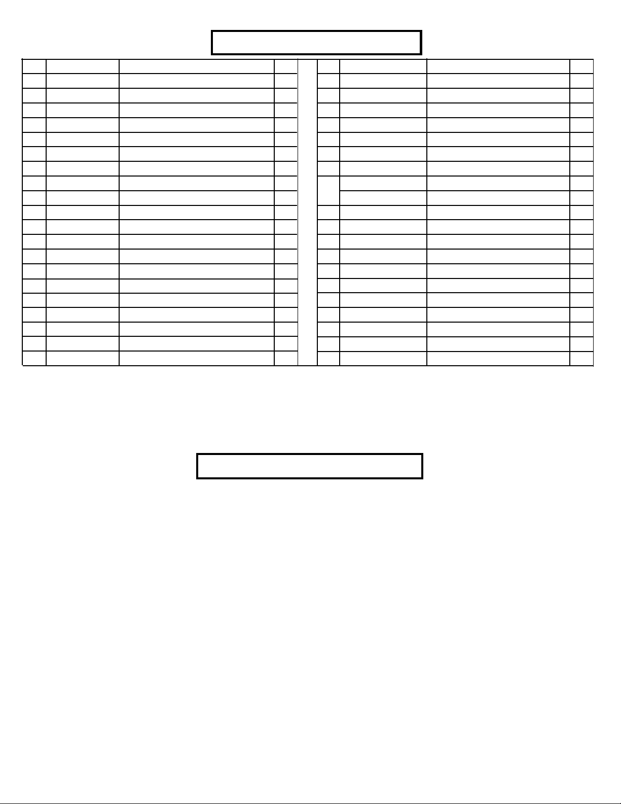
PAR TS LIST
KEY
1
2
3
4
5
6
7
8
9
10
11
12
13
14
15
16
17
18
19
20
PART #
ACU04-1661
ACU04-1657
ACU04-1659
ACU04-1660
ACU04-1658
ACU02-1648
ACU06-0025
ACU06-0304
ACU01-2387
ACU72925
ACU73086
ACU10-0204ASY
ACU05-0212
ACU08-0087
ACU08-0073
ACUDA1C03804316NU
ACUDA1C03805016NU
ACUDA1C03807316NU
ACUDA1C03808616NU
ACUDA1C03809016NU
DESCRIPTION
TOWER
BASE FRAME
PULLEY BOOM
REAR UPRIGHT
FOOT PLA TE
BAR SUPPORT
4-1/2” PULLEY
3/4 X 2” WEIGHT ST ACK CUSHION
GUIDE ROD
WEIGHT PLA TE
WEIGHT ST ACK LABEL
HEAD PLA TE ASSEMBL Y
13/16” SHAFT COLLAR
3/8 X 1-1/4” FLANGE SP ACER
3/8 X 1” FLANGE SP ACER
3/8 X 43mm BOL T
3/8 X 50mm BOL T
3/8 X 73mm BOL T
3/8 X 86mm BOL T
3/8 X 90mm BOL T
QTY
1
1
1
1
1
2
7
2
2
20
1
1
2
4
4
6
2
2
1
2
KEY
21
22
23
24
25
26
27
28
OR
29
30
31
32
33
34
35
36
37
38
39
PART #
ACUDA1C03809716NU
ACUDAEC03802516YB
ACUDC1250100020B
ACUDB2E03807200U
ACUDC120010510U
ACU05-0310
ACU06-0357
ACU06-0357
ACU06-0357
ACU13-0169
ACUDI1080080U
ACU04-1662
ACU10-0238
ACU10-0229
ACU10-0231
ACU10-0232
ACUDB9E03813016B
ACUDA1C03810216NU
ACUDAEC03809016NB
ACUDC1250100020U
DESCRIPTION
3/8 X 97mm BOL T
3/8 X 25mm BUTTON HEAD BOL T
3/8” BLACK FLA T W ASHER
3/8” LOW HEIGHT LOCK NUT
3/8” SAE W ASHER
3/8” RH WASHER
BLACK RH CAP
WHITE RH CAP
PLA TINUM RH CAP
BI/TRI CABLE
SNAP LINK
CURL BAR
TRICEPS ROPE
TOP SHROUD
FRONT SHROUD
REAR SHROUD
3/8” ACORN NUT
3/8 X 102mm BOL T
3/8 X 90mm BUTTON HEAD BOL T
3/8” FLA T WASHER
QTY
5
2
22
20
36
36
4
32
32
1
1
1
1
1
1
1
10
2
10
4
T ools Required for Assembly
* 9/16” wrench
* Ratchet with 9/16” socket
* Metric Allen wrench set
2
Page 3

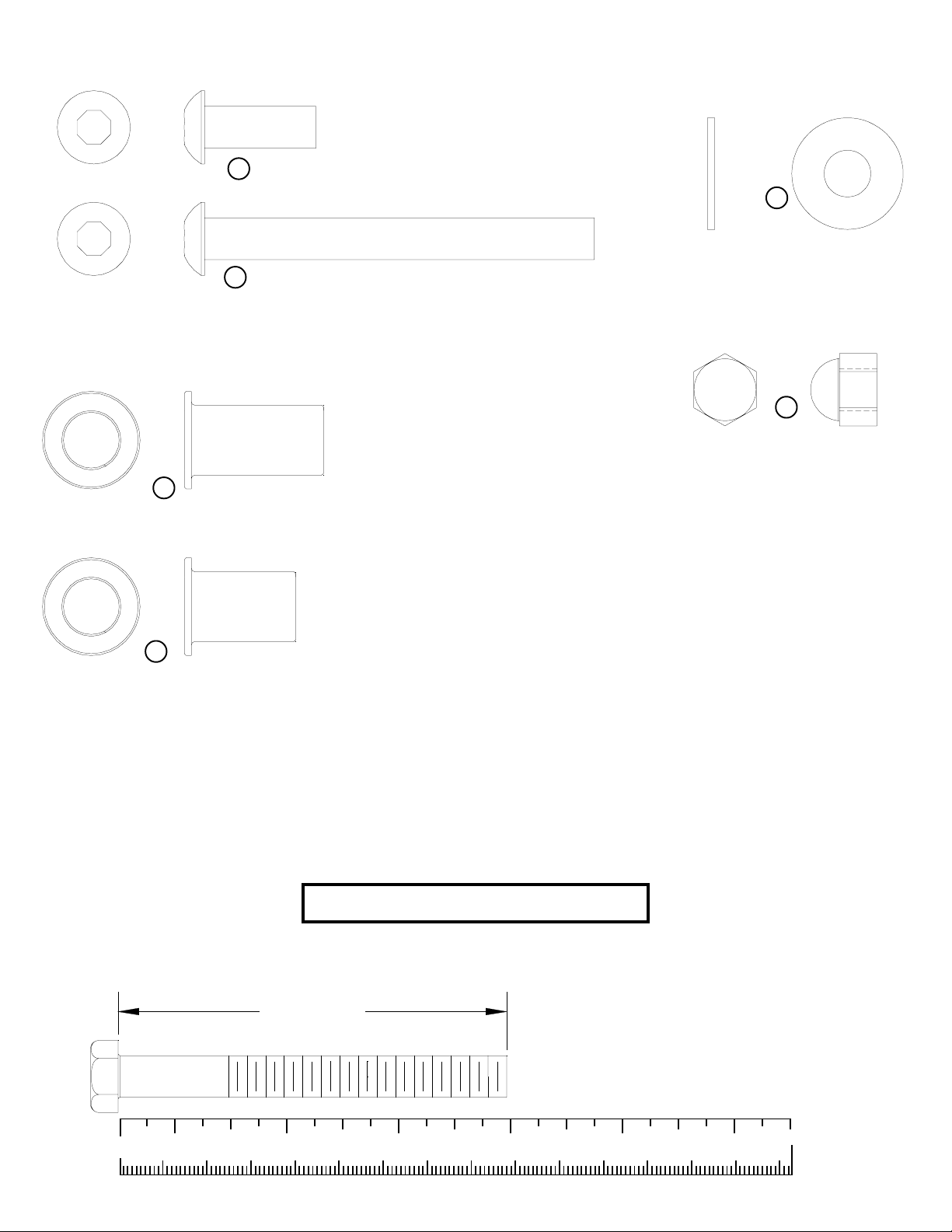
16 3/8 X 43mm BOL T
17 3/8 X 50mm BOL T
18 3/8 X 73mm BOL T
24
3/8” LOW
HEIGHT LOCK
NUT
25
3/8” SAE
WASHER
19 3/8 X 86mm BOL T
20 3/8 X 90mm BOLT
21 3/8 X 97mm BOL T
23
3/8” BLACK
FLA T W ASHER
27
28
RH CAP
(WHITE/PLATINUM/BLACK)
26
RH
WASHER
37 3/8 X 102mm BOL T
3
Page 4
22 3/8 X 25mm BUTTON HEAD BOL T
38 3/8 X 90mm BUTTON HEAD BOL T
14
3/8 X 1-1/4” FLANGE SP ACER
39
3/8”
FLA T WASHER
36
3/8”
ACORN NUT
15
3/8 X 1”
FLANGE SP ACER
Bolt Length Ruler
NOTE: BOL T LENGTH IS MEASURED FROM THE UNDERSIDE OF THE HEAD OF THE BOLT .
BOLT LENGTH
0
1/2 1/2 1/2 1/2 1/2 1/2
10 20 30 40 50 60 70 80 90 100 110 120 130 140 150
1
23456
4
Page 5
1
24
2
26
25
28
3/8 X 97mm 21
3/8 X 97mm 21
5
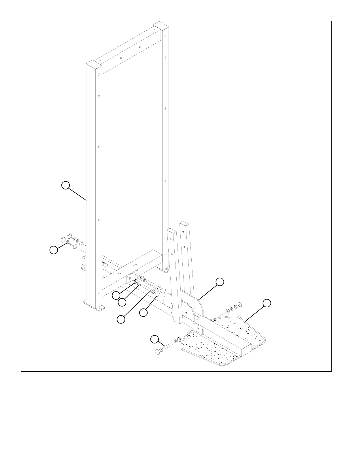
FIGURE 1
STEP 1:
• SECURELY assemble the FOOT PLA TE (5) to the BASE FRAME (2) using two RH CAPS (28), one 3/8 X 97mm BOLT (21), two 3/8”
SAE WASHERS (25), two 3/8” RH W ASHERS (26) and one 3/8” LOW HEIGHT LOCK NUT (24) as shown in FIGURE 1.
• SECURELY assemble the TOWER (1) to the BASE FRAME (2) using four RH CAPS (28), two 3/8 X 97mm BOLTS (21), four 3/8”
SAE W ASHERS (25), four 3/8” RH W ASHERS (26) and two 3/8” LOW HEIGHT LOCK NUTS (24) as shown in FIGURE 1.
5
Page 6

4
24
26
25
3/8 X 97mm 21
28
2
FIGURE 2
STEP 2:
• LOOSELY assemble the REAR UPRIGHT (4) to the BASE FRAME (2) using four RH CAPS (28), two 3/8 X 97mm BOL TS (21), four 3/
8” SAE W ASHERS (25), four 3/8” RH W ASHERS (26) and two 3/8” LOW HEIGHT LOCK NUTS (24) as shown in FIGURE 2.
6
Page 7

3/8 X 43mm 16
28
7
24
29
26
25
12
ADJUSTMENT
FIGURE 3
STEP 3:
• Route the BI/TRI CABLE (29) around one 4-1/2” PULLEY (7) and SECURELY assemble the 4-1/2” PULLEY (7) to the BRACKET on the
HEAD PLA TE (12) using four RH CAPS (28), two 3/8 X 43mm BOL TS (16), four 3/8” SAE W ASHERS (25), four 3/8” RH WASHERS (26)
and two 3/8” LOW HEIGHT LOCK NUTS (24) as shown in FIGURE 2. (NOTE: Make sure CABLE runs over the retaining bolt.)
7
Page 8

3
13
9
12
10
1
8
FIGURE 4
STEP 4:
• Insert two GUIDE RODS (9) into the TOWER (1) as shown on FIGURE 4.
• Slide two 3/4 X 2” WEIGHT ST ACK CUSHIONS (8) down over the GUIDE RODS (9) as shown in FIGURE 4.
• Using EXTREME CARE slide all twenty WEIGHT PLA TES (10) down over the GUIDE RODS (9) on to the WEIGHT ST ACK CUSHIONS
(8). Make sure that the WEIGHT PLATES (10) are all facing as shown.
• Slide the HEAD PLA TE ASSEMBL Y (12) down over the GUIDE RODS (9) onto the weight stack as shown in FIGURE 4.
• Slide two 13/16” SHAFT COLLARS (13) and the PULLEY BOOM (3) over the GUIDE RODS (9) as shown in FIGURE 4.
8
Page 9

FIGURE 5
13
TIGHTEN!
24
39
1
4
3
18 3/8 X 73mm
27 BLACK
28
24
2
6
26
BLACK 27
25
16 3/8 X 43mm
STEP 5:
• SECUREL Y assemble the PULLEY BOOM (3) to the TOWER (1) and the REAR UPRIGHT (4) using two 3/8 X 73mm BOL TS (18),
four 3/8” FLA T W ASHERS (39) and two 3/8” LOW HEIGHT LOCK NUTS (24) as shown in FIGURE 5.
• Slide the 13/16” SHAFT COLLARS (13) up against the PULLEY BOOM (3) and SECURELY tighten the set screws on the SHAFT
COLLARS (13). See FIGURE 5.
• SECURELY assemble the two BAR SUPPOR TS (6) to the BASE FRAME (2) using four BLACK RH CAPS (27), four RH CAPS (28),
four 3/8 X 43mm BOL TS (16), eight 3/8” SAE WASHERS (25), four 3/8” RH W ASHERS (26) and four 3/8” LOW HEIGHT LOCK
NUTS (24) as shown in FIGURE 5.
9
Page 10

LUBRICATION NOTE:
When finished assembling the W eight Stack, open the lube Pack provided
with this unit and apply a thin film of Lubricant around the first 2 to 3
inches of each Guide Rod above the Head Plate Assembly . After the
cables are installed, use of the machine will spread the lubricant over the
length of the Guide Rods and into the Head Plate
bushings
TIGHTEN!
FIGURE 6
STEP 6:
• Securely tighten all loose frame connections made to this point, then proceed to snap RH CAPS
(27)(28) over the RH WASHERS (26) on all tightened connections.
10
Page 11

FIGURE 7
3/8 X 50mm 17
24
3
29
26
25
28
7
STEP 7:
• Route the BI/TRI CABLE (29) through the PULLEY BOOM (3) and SECURELY assemble two 4-1/2” PULLEYS (7) to the BOOM (3)
using four RH CAPS (28), two 3/8 X 50mm BOL TS (17), four 3/8” SAE WASHERS (25), four 3/8” RH W ASHERS (26), and two 3/8”
LOW HEIGHT LOCK NUTS (24) as shown in FIGURE 7.
7
24
4
29
14
26
25
37 3/8 X 102mm
28
FIGURE 8
STEP 8:
• Route the BI/TRI CABLE (29) inside the REAR UPRIGHT (4) and SECURELY assemble one 4-1/2” PULLEY (7) to the REAR UP-
RIGHT (4) using two RH CAPS (28), one 3/8 X 102mm BOL T (37), two 3/8” SAE WASHERS (25), two 3/8” RH WASHERS (26), two
3/8 X 1-1/4” FLANGE SP ACERS (14) and one 3/8” LOW HEIGHT LOCK NUT (24) as shown in FIGURE 8.
11
Page 12

4
2
29
24
7
14
26
25
FIGURE 9
3/8 X 102mm 37
28
STEP 9:
• Continue to route the BI/TRI CABLE (29) inside the REAR UPRIGHT (4) and BASE FRAME(2) and SECURELY assemble one 4-1/2”
PULLEY (7) to the REAR UPRIGHT (4) using two RH CAPS (28), one 3/8 X 102mm BOLT (37), two 3/8” SAE W ASHERS (25), two 3/8”
RH W ASHERS (26), two 3/8 X 1-1/4” FLANGE SPACERS (14) and one 3/8” LOW HEIGHT LOCK NUT (24) as shown in FIGURE 9.
12
Page 13

29
24
7
2
15
26
FIGURE 10
28
3/8 X 90mm 20
25
STEP 10:
• Route the BI/TRI CABLE (29) between two 4-1/2” PULLEYS (7) and SECUREL Y assemble the 4-1/2” PULLEYS (7) to the BASE FRAME
(2) using four RH CAPS (28), two 3/8 X 90mm BOL TS (20), four 3/8” SAE WASHERS (25), four 3/8” RH W ASHERS (26), four 3/8 X 1”
FLANGE SP ACERS (15) and two 3/8” LOW HEIGHT LOCK NUTS (24) as shown in FIGURE 10.
29
24
2
26
25
28
FIGURE 11
3/8 X 86mm 19
STEP 1 1:
• SECUREL Y assemble one 3/8 X 86mm retaining BOL T (19) to the BASE FRAME (2) using two 3/8” SAE WASHERS (25), two 3/8” RH
W ASHERS (26), one 3/8” LOW HEIGHT LOCK NUT (24) and two RH CAPS (28) as shown in FIGURE 11. (NOTE: Make sur e the BI/
TRI CABLE (29) runs in the groove of the PULLEY .)
13
Page 14

29
32
ADJUSTMENT
7
12
10
11
31
30
FIGURE 12
STEP 12:
• Assemble the TRICEPS ROPE (32) to the BI/TRI CABLE (29) as shown in FIGURE 12.
• Assemble the CURL BAR (31) to the BI/TRI CABLE (29) using one SNAP LINK (30) as shown in FIGURE 12.
• To adjust cable tension, disassemble the 4-1/2” PULLEY (7) and loosen both jam nuts under the bracket on the HEAD PLA TE (1 2).
Adjust the bolt accordingly. Retighten jam nuts and reassemble the 4-1/2” PULLEY (7).
• Apply WEIGHT ST ACK LABELS (11) to WEIGHT PLATES (10) and HEAD PLA TE (12) as shown in FIGURE 12. Begin with number
one at the HEAD PLATE (12) with larger numbers in consecutive order towards bottom of weight stack.
14
Page 15

FIGURE 12
22 3/8 X 25mm BUTTON HEAD
33
35
36
23
1
34
38 3/8 X 90mm BUTTON HEAD
SERIAL # LOCA TION
STEP 13:
• SECURELY assemble the TOP SHROUD (33) to the TOWER (1) using two 3/8 X 25mm BUTTON HEAD BOLTS (22) and two 3/8”
BLACK FLA T WASHERS (23) as shown above.
• SECUREL Y assemble the FRONT SHROUD (34) and the REAR SHROUD (35) to the TOWER (1) using ten 3/8 X 90mm BUTTON HEAD
BOL TS (38), twenty 3/8” BLACK FLA T WASHERS (23) and ten 3/8” ACORN NUTS (36) as shown above.
Thank you for purchasing the LifeFitness FIT SERIES BICEPS/TRICEPS. If unsure of proper use of equip-
ment, call your local LifeFitness distributor or call the LifeFitness customer service department at
(800) 351-3737.
15
Page 16

CAUTION-PLEASE READ
There is a risk assumed by individuals who use this type of equipment. To minimize risk, please
follow these rules:
1. Inspect equipment daily . T ighten all loose connections and replace worn parts immediately.
Failure to do so may result in serious injury.
2. Do not allow minors or children to play on or around this equipment.
3. Exercise with care to avoid injury .
4. Consult your physician before beginning any exercise program.
WARRANTY INFORMA TION
10 YEARS STRUCTURUAL FRAME
1 YEAR PILLOW BLOCKS, PULLEYS, WEIGHT PLATES AND GUIDE RODS
1 YEAR CABLES
90 DA YS UPHOLSTERY
PREVENT ATIVE MAINTENANCE TIPS
Action DAILY WEEKLY QUARTERLY BI-ANNUALLY AS NEEDED
CLEAN
Uphol s tery
Guide Rods
Hand Grips
INSPECT
Visual Overall
Cabl e s
Hardware
Frame
Hand Grips
LUBRICATE
Guide Rods
X
X
X
X
X
X
X
X
X
Clean:
• Upholstery with mild soap and water.
• Guide rods with a cotton cloth.
• Hand grips with mild soap and water.
• Frame damage can be repaired with touch-up paint can be purchased from your LifeFitness customer service representative at (800)
351-3737
Inspect:
• Cables for wear or damage and proper tension (should not exceed 3/4” deflection.) Pay close attention at bends and attachment
points.
• Hardware should be checked for looseness. Tighten as required.
• Frames should be inspected for wear or damage.
• Hand Grips should be checked for wear or damage
Lubricate:
• Lube the Guide Rods. Apply the lubricant to a cotton cloth, then run the cotton cloth up and down the guide rods as needed. Do not
spray lubricant directly on the Guide Rods.
Thank you for purchasing the LifeFitness FIT SERIES BICEPS/TRICEPS. If unsure of proper use of equip-
ment, call your local LifeFitness distributor or call the LifeFitness customer service department at
(800) 351-3737.
16
 Loading...