

Page 1
Life Fitness Sport, Essential and
Ballys Consumer Treadmills
Customer Support Services
SERVICE MANUAL
Page 2

Life Fitness Sport and Essential Consumer Treadmills
INTRODUCTION
This service manual is applicable to Consumer Folding Treadmill. Information in this manual
represents typical configuration and may differ slightly from actual equipment. The Service
Manual provides recommendations for safe and efficient approaches to problem situations.
This manual consists of:
Section I
! TROUBLESHOOTING
Section II
! DIAGNOSTICS
Section III
! “HOW TO…”
Section IV
! ELECTRONICS
Section V
! MISCELLANEOUS
If an operating problem should arise, turn to the TROUBLESHOOTING GUIDES and attempt to
isolate what is causing the malfunction. The GUIDES are suggestions to the most probable
cause.
Refer to the appropriate "How To..." which covers step-by-step procedures for the replacement
or adjustment of parts. Use of basic hand tools is all that is required to perform most service
procedures. If special service tools are required, then “Special Tools Required“ will be listed in
the title page.
FAX or call Life Fitness Customer Support Services, Monday through Friday, 8:00 AM to 5:00
PM Central Standard Time. To better assist you in a more efficient and expedient manner,
please have the following information ready for the Customer Service Technician as follows:
1. Equipment model number
2. Serial number
3. Symptom of the problem
4. Part name and number to order
If you have any questions or comments please phone, mail, or fax Life Fitness at:
LIFE FITNESS COMPANY - CUSTOMER SUPPORT SERVICES
10601 Belmont Avenue, Franklin Park, IL 60131; USA
Telephone: 847-451-0036, Toll Free: 800-351-3737, FAX: 847-288-3702
Page 3

Life Fitness Sport and Essential Consumer Treadmills
SPECIAL SERVICE TOOL REQUIREMENTS
Unless otherwise specified, only basic hand tools are required to perform service procedures
outlined in this section. Some of these standard tools should consist of: Philips and StraightBlade Screw Drivers, Torx Set, Pliers, Rubber Mallet, Pry Bar, Snap Ring Pliers (internal and
external), Standard and Metric; Allen Wrenches, Socket Sets, and Hand Wrenches.
Specialized tools will be listed after the sub-heading Special Service Tools:, which appears
below the Service Procedure Heading at the top of the page. If no specialized tools are
required, then the title would read: Special Service Tools: NONE, which means that standard
hand tools should be employed to provide service to the product.
Specialized tools must be used to ensure safe and effective service procedures. Improvisation
or attempts to use any other tool could result in unnecessary damage to the equipment or
personal injury.
ii
Page 4

Life Fitness Sport and Essential Consumer Treadmills
TABLE OF CONTENTS
SECTION I TROUBLESHOOTING GUIDES
NO POWER........................................................................................................................................2
UNIT RESETS RANDOMLY OR PAUSES.........................................................................................2
ERR1...................................................................................................................................................2
ERR2...................................................................................................................................................2
ERR2...................................................................................................................................................2
ERR5...................................................................................................................................................3
ERR11.................................................................................................................................................3
KNOCKING AT REAR OF UNIT.........................................................................................................3
KNOCKING FROM DECK ..................................................................................................................3
RUBBING SOUND..............................................................................................................................3
SQUEAKING NOISE...........................................................................................................................3
GROANING SOUND ..........................................................................................................................3
RUNNING BELT TRACKING BEYOND LIMITS.................................................................................3
RUNNING BELT SLIPS......................................................................................................................4
MAX SPEED REDUCED ....................................................................................................................4
DISPLAY READS CONTINUOUS HEART RATE ..............................................................................4
NO CHEST STRAP DETECTED (IF EQUIPPED)..............................................................................4
SECTION II DIAGNOSTICS
T810 CONSOLE................................................................................................................................ 2
TRAINING W/O PRESET PROGRAM .............................................................................................. 3
QUICK START................................................................................................................................... 3
MANUAL MODE................................................................................................................................ 3
TRAINING WITH USER SET TARGETS .......................................................................................... 3
TO WORKOUT WITH TARGET SETTING MODES......................................................................... 3
TRAINING WITH PRESET PROGRAMS.......................................................................................... 3
TO WORKOUT WITH PRESET PROGRAMS.................................................................................. 4
T830 CONSOLE................................................................................................................................ 5
METRIC TO MILES........................................................................................................................... 6
WIRELESS HEART RATE CONSOLE ............................................................................................. 6
PERCENT OF MAX HEART RATE................................................................................................... 6
VIEW.................................................................................................................................................. 6
COOL DOWN .................................................................................................................................... 6
SPEED ADJUSTMENTS................................................................................................................... 6
ELEVATION ADJUSTMENTS...........................................................................................................6
PAUSE............................................................................................................................................... 6
END OF WORKOUT ......................................................................................................................... 6
QUICK START................................................................................................................................... 7
CUSTOM PROGRAM A&B............................................................................................................... 7
SPEED PROGRAMS......................................................................................................................... 8
ELEVATION PROGRAMS ................................................................................................................ 8
HEART RATE CONTROL PROGRAM ............................................................................................. 9
TARGET SETTING PROGRAMS ..................................................................................................... 9
TARGET BY TIME............................................................................................................................. 9
TARGET BY DISTANCE................................................................................................................... 9
TARGET BY CALORIES................................................................................................................... 10
iii
Page 5

Life Fitness Sport and Essential Consumer Treadmills
TABLE OF CONTENTS - CONTINUED
SECTION III HOW TO…REPLACE THE…
RUNNING BELT AND DECK............................................................................................................ 2
ADJUST RUNNING BELT TENSION ............................................................................................... 4
ADJUST RUNNING BELT AND TRACKING.................................................................................... 5
MOTOR DRIVE BELT ....................................................................................................................... 6
DRIVE MOTOR.................................................................................................................................. 7
FRONT ROLLER............................................................................................................................... 8
REAR ROLLER................................................................................................................................. 9
DECK CUSHION ............................................................................................................................... 10
INCLINE MOTOR .............................................................................................................................. 11
MOTOR CONTROLLER ................................................................................................................... 12
MOVING WHEEL .............................................................................................................................. 13
CONSOLE PCB................................................................................................................................. 14
SECTION IV ELECTRONICS
T810 CONSOLE................................................................................................................................ 2
T830 CONSOLE................................................................................................................................ 3
MOTOR CONTROLLER PCB........................................................................................................... 4
T810 BLOCK DIAGRAM................................................................................................................... 5
T830 BLOCK DIAGRAM................................................................................................................... 6
WIRING DIAGRAM (CE VERSION).................................................................................................. 7
WIRING DIAGRAM (NONE CE VERSION)....................................................................................... 8
SECTION V MISCELLANEOUS
MODEL ID AND S/N..........................................................................................................................2
PREVENTIVE MAINTENANCE TIPS................................................................................................ 3
UNPACKING INSTRUCTIONS .........................................................................................................4
INSTALLATION INSTRUCTIONS..................................................................................................... 5
NOTES...............................................................................................................................................10
iv
Page 6

Life Fitness Sport and Essential Consumer Treadmills
SECTION I
TROUBLESHOOTING
GUIDES
1
Page 7
Life Fitness Sport and Essential Consumer Treadmills
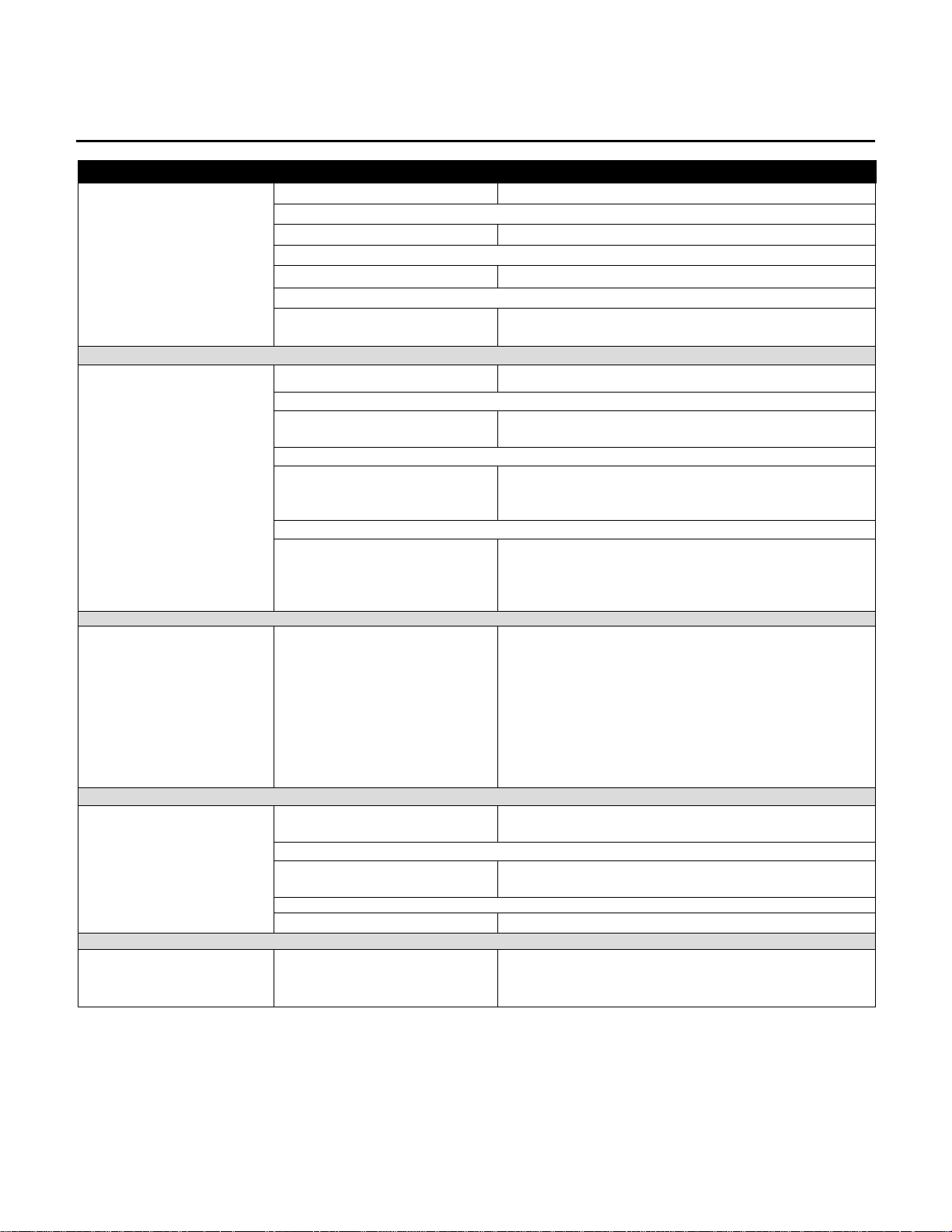
TROUBLESHOOTING
Malfunction Probable Cause Corrective Action
No Power.
On/Off switch. Turn the switch to the ON position.
Insufficient power source. Refer to the Operation Manual.
Damaged line cord. Replace line cord.
Unit resets randomly or
pauses.
Or console buttons are
not responding when
depressed.
Display reads:
Err 1- speed sensor error
Line cord improperly seated
in socket.
Insufficient power source. Refer to the Operation Manual.
Line cord improperly seated
in electrical outlet.
Loose or damaged cable
connections at display
console or motor controller.
Open ground path.
Motor speed is not correctly
feed back to the controller
and console.
Inspect power connection at wall outlet and at
machine for proper contact.
Inspect power connection at electrical outlet and at
machine for proper contact.
Disconnect and reconnect cable at motor controller
and console. Replace cable if necessary.
Using multi-meter, check all points for continuity:
console mounting screws, handlebar screws, and
upright post screws to frame with respect to ground.
Ground must be a non-painted surface.
Clean sensor of dust
Change sensor cable
Change communication cable
Change console
Display reads:
Err 2 – over speed error
Display reads:
Err 3 – safety tether key
error
Replace controller.
Belt had moved befor e motor
actually move.
User is pushing hard on the
running belt.
Controller is damaged. Replace controller.
Safety Key does not have
positive contact.
Turn power off and on again to reset.
Turn power off and on again to reset.
Check positive contact of the safety key to the
console. Replace safety key.
2
Page 8
Life Fitness Sport and Essential Consumer Treadmills
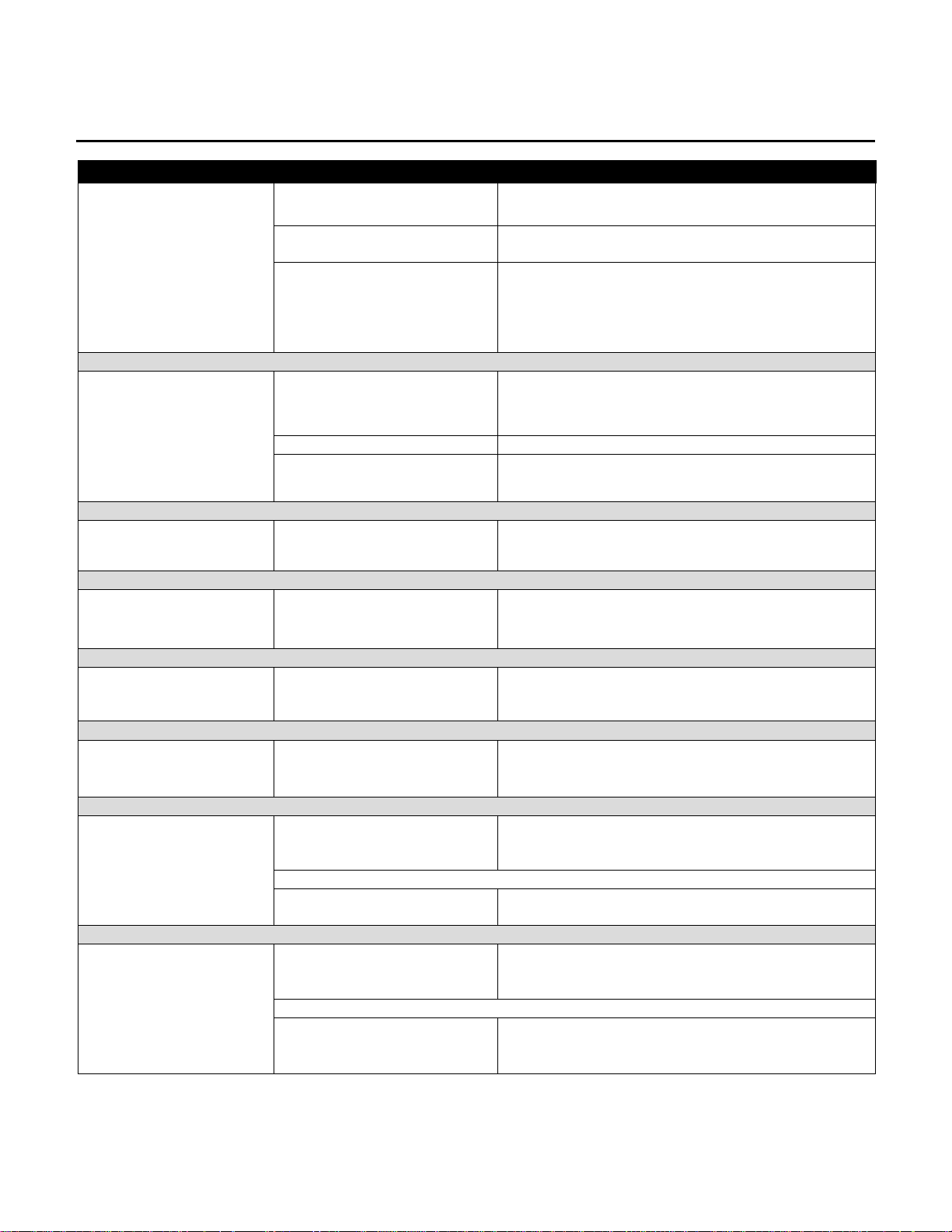
TROUBLESHOOTING
Malfunction Probable Cause Corrective Action
Display reads:
Err 5– incline motor error
Lift actuator not calibrated. Refer to Incline Motor “How To…” procedure.
Incline motor is over-loaded
or over-heated.
Lost connection of incline
motor sensor cable.
Simply wait until the incline motor has returned to
normal temperature then try again.
Check sensor connection cable of incline motor.
Replace sensor connection cable.
Replace incline motor.
Display reads:
Err 11 – communication
error
Knocking sound at rear of
machine.
Knocking sound coming
from deck.
Rubbing sound from
underneath machine.
Squeaking noise. Drive motor belt may be worn
Loud groaning sound
heard from front of
machine while inclin ing .
Communication cable does
not have a good connection.
Insufficient power source. Refer to the Operation Manual.
Faulty rear roller bearings. Replace rear roller assembly.
Cushions not positioned
correctly and/or loose
mounting hardware.
Foreign objects may be stuck
underneath the machine.
or misaligned.
Incline mechanism pivot
points or incline screw are
dry.
Check or replace cable between console and
controller.
Reposition or tighten cushions.
Inspect underneath running belt and machine.
Remove any debris or objects that may cause
interference with the treadmill.
Replace drive motor belt. See How To…
Replace Drive Motor Belt.
Lubricate pivot or incline screw with grease.
The Running Belt is
traveling beyond the
tracking limits.
Faulty Incline motor. Replace the Incline motor. See How To…Replace
Incline Motor.
Running b elt needs to be retensioned or tracking needs
adjustment.
Worn running belt or user
pushing belt.
Refer to belt tensioning or tracking adjustment
procedure in operation or service manual.
Center running belt according to belt centering
technique. See How To…Adjust And Tension The
Running Belt.
3
Page 9
Life Fitness Sport and Essential Consumer Treadmills
TROUBLESHOOTING
Malfunction Probable Cause Corrective Action
Running Belt slips during
footfall.
Running belt slips on front
roller during stall test.
Check running belt & re-tension as necessary.
See How…To Adjust Belt Tension.
Maximum speed is
reduced.
Display reads a continuous
heart rate.
No Chest Strap detected (if
equipped).
User is pushing running belt.
Running belt needs
lubrication.
RF interference. Move machine to a different location.
Chest strap sensors not making
good contact with body of user.
User is out of monitoring range. Move within 3 ft (1 meter) of receiver.
Loose connection at receiver. Check connection on receiver.
Faulty chest strap. Replace chest strap.
Faulty receiver. Replace receiver in the console board.
Instruct users not to push running belt in either
direction.
Put silicone on deck.
Adjust chest strap and moisten sensors to make
better contact with skin.
4
Page 10

Life Fitness Sport and Essential Consumer Treadmills
SECTION II
DIAGNOSTICS
1
Page 11
Life Fitness Sport and Essential Consumer Treadmills
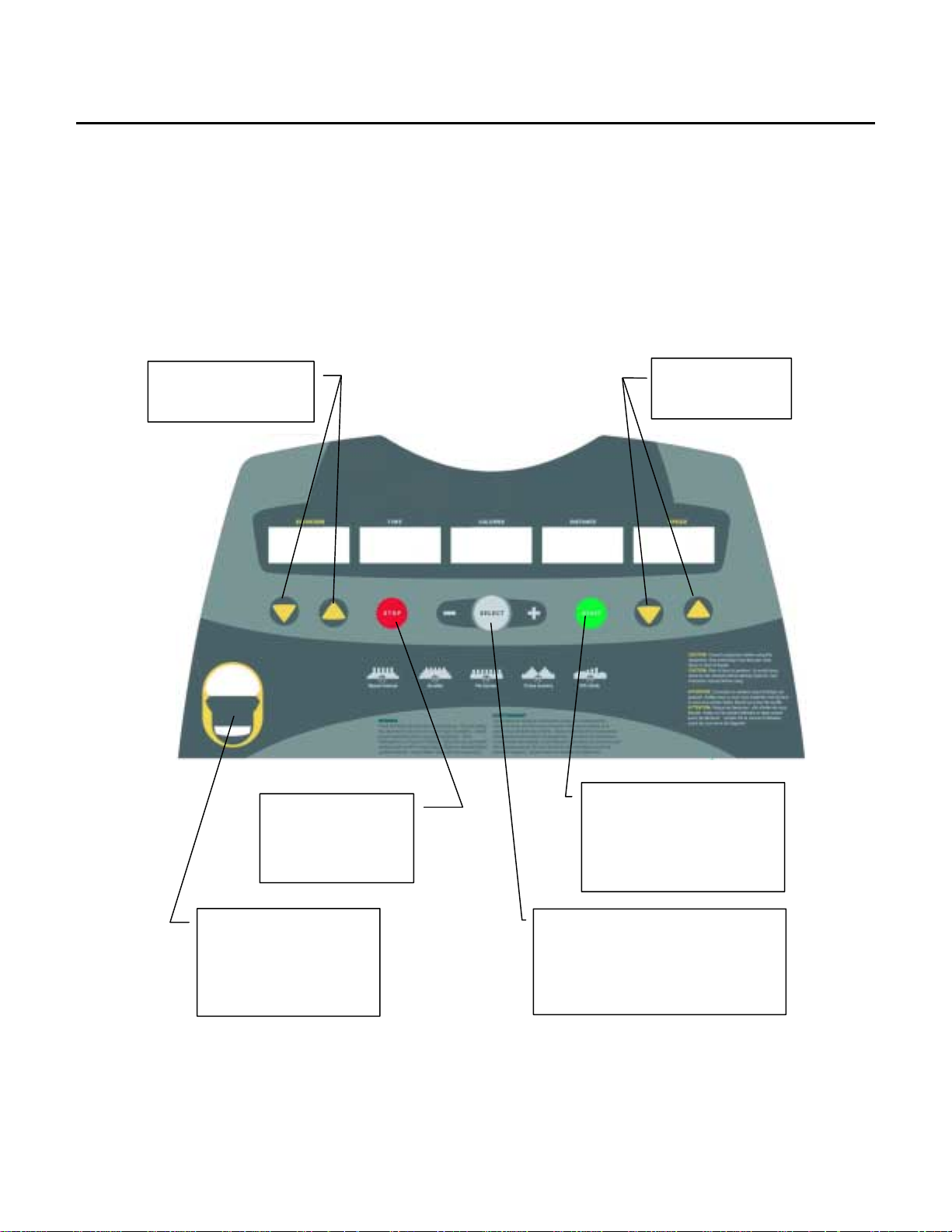
T810 CONSOLE
DISPLAY VALUES
Elevation 0 – 10% grade 1% increment
Time 0:00 to 59:59 One second increment
Calories 0 – 999 calories One calories increment
Distance 0 – 99.9 Km 0.1 Km increment
Speed 1 – 16 Km/H 0.1 Km/H increment
FUNCTION KEYS
Up / Down - Adjusts
elevation up and down.
Stop – slows the
running belt slowly
to a complete stop.
Fast / Slow - Adjusts
speed
Start – activates and slowly
increases the speed of the
running belt until reaches
your set training speed.
Safety tether key –
For emergency stop only.
It will cut off main power
immediately.
Select – chooses one of four
modes: program mode, distance
based mode, calories based mode,
and time based mode.
+/- keys selects program or sets
2
Page 12

Life Fitness Sport and Essential Consumer Treadmills
T810 CONSOLE - Continued
TRAINING WITHOUT PRESET PROGRAM
Once the power is turned on and the safety key is secured in place, you will see all values display zero. Select one
of the following methods to workout with your treadmill.
QUICK START
Manually controlled workout. No time limitation. Speed preset at 1Km/H at 0% elevation. During workout, user may
adjust speed and or elevation. Simply press START, after a three second count down, treadmill will pick up speed.
NOTE: Once the power is on and the safety tether key is secured in place, simply press the green start button, and
a three second count down will activate and maintain the running mat at 1Km/H.
MANUAL MODE
Manually controlled workout. No time limitation. User set speed and or elevation. During workout, user may adjust
speed and or elevation, then press START. After a three second count down, treadmill will pick up speed.
TRAINING WITH USER SET TARGETS
Users have the option to set training target to achieve their fitness goals. Users may set targets with distance,
calories or time. This type of workout has speed preset at 1Km/H and elevation at 0% grade. During workout user
may adjust speed and or elevation.
Target Distance
User set workout with target distance.
Maximum target distance: 99.9 Km.
Target Calories
User set workout with target calories.
Maximum target: 999 calories.
Target Time
User set workout with target length of time.
Maximum target: 60 minutes.
TO WORKOUT WITH TARGET SETTING MODES:
1. Turn on the power
2. Secure the safety key in place
3. Press SELECT to choose time or distance or calories mode
4. Use + - key to set the target value
5. Press START to activate treadmill
6. After a three second count down, treadmill will pick up speed
TRAINING WITH PERSET PROGRAMS
There are five pre-set programs. Each program is 30 minutes long, divided into 15 segments each 2 minutes long.
User may select intensity level of the workout by selecting the top speed in speed-based programs or the top
elevation in the elevation-based programs.
Speed programs – workout will vary by speed according to preset profile. During data entry, user may adjust top
speed, which is preset at 10 Km/H. During workout, user may adjust elevation, but not speed.
● P1 – Speed interval
● P2 – Weight loss
Elevation programs – workout will vary by elevation according to preset profile. During data entry, user may adjust
top elevation, which is preset at 8% grade. During workout, user may adjust speed, but not elevation.
● P3 – Fat burner
● P4 – Cross country
● P5 – Hill climb
3
Page 13

Life Fitness Sport and Essential Consumer Treadmills
T810 CONSOLE - Continued
TO WORKOUT WITH PRE-SET PROGRAMS:
1. Turn on the power
2. Secure the safety key in place
3. Press SELECT until P1 shows
4. Use + - keys to choose the desired program: P1 – P5
5. Use to adjust the intensity level ( top speed or maximum elevation ) if the preset is not appropriate
6. Press START to activate treadmill
7. After a three second count down, treadmill picks up speed
NOTE: This model is not designed for therapeutic purposes. Calories consumption values displayed on the console
are motivational values only.
4
Page 14
Life Fitness Sport and Essential Consumer Treadmills
y
V
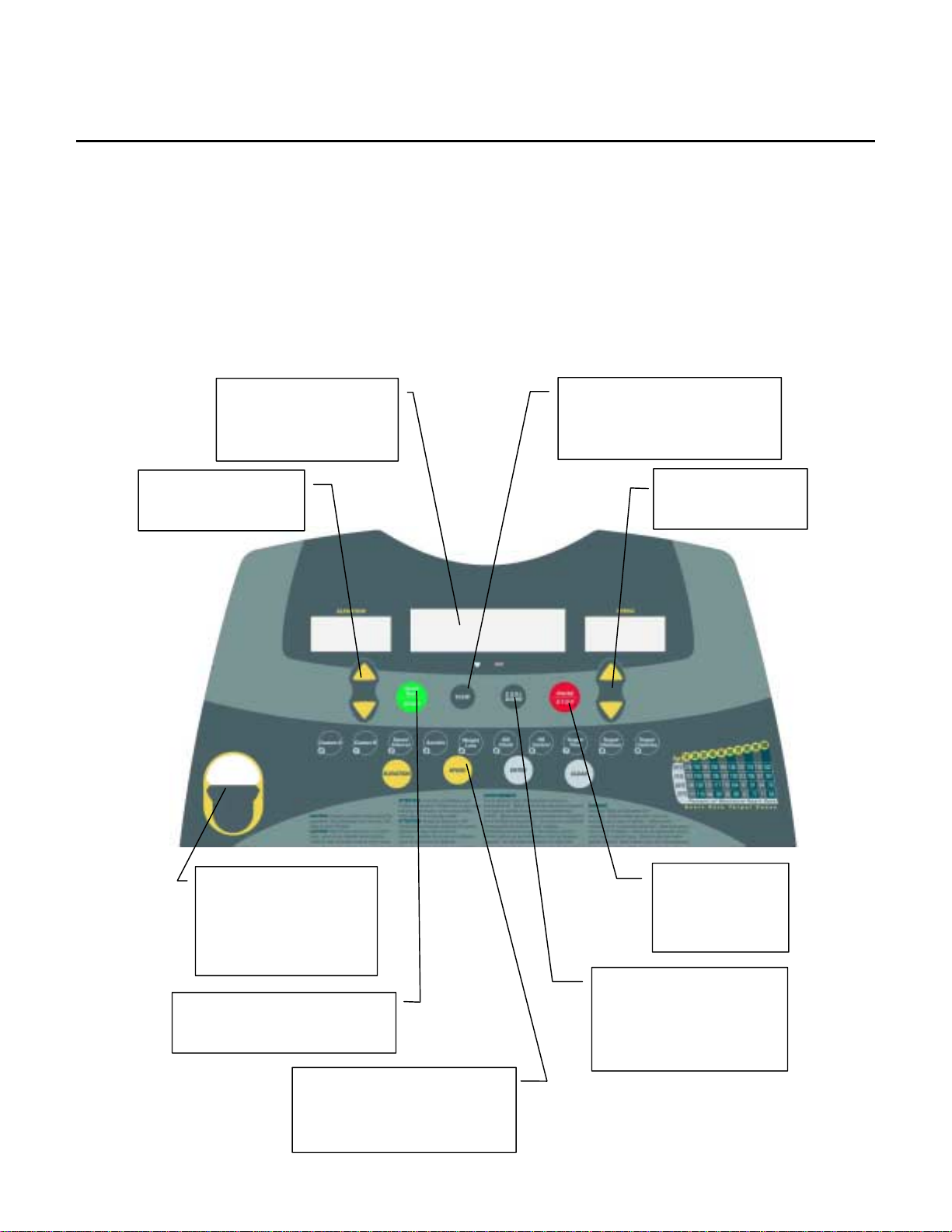
T830 CONSOLE
DISPLAY VALUES
Elevation 0 – 10% grade 1% increment
Time 0:00 to 59:59 One second increment
Calories 0 – 999 calories One calories increment
Pulse 40 – 240 One pulse beat increment
Distance 0 – 99.9 Km 0.1 Km increment
Speed 1 – 16 Km/H 0.1 Km/H increment
FUNCTION KEYS
Message board – gives
user instructions during
programming and
workout
Up / Down - Adjusts
elevation up and down.
iew – SCAN or displays Time,
Distance, Calories, Pulse, or %
of maximum heart rate.
Fast / Slow - Adjusts
speed
Safety tether ke
For emergency stop only.
It will cut off main power
immediately.
Quick Start – manual workout
Start – to activate treadmill
–
Pre-set programs – 2 custom
programs, heart rate control,
elevation and speed
programs…
Cool down -- interrupts the
current workout and go
directly into a four minute
cool down routine
Stop – slows the
running belt to a
complete stop.
5
Page 15

Life Fitness Sport and Essential Consumer Treadmills
T830 CONSOLE - Continued
The heart rate control console presents many user-friendly features. There are displayed messages to guide you
through every step of the programming and workout.
NOTE: To view pulse or % of maximum heart rate, you must wear the heart rate transmitter chest strap.
METRIC TO MILES
You have the option to change from miles to Km and vise versa by pressing FAST + SLOW + 0 (three keys at the
same time).
WIRELESS HEART RATE CONSOLE
The treadmill features wireless heart rate monitoring, the most advanced technology to date for accurate read out
of your heart beat. You must wear the heart rate transmitter chest strap so that the contact surface is next to your
skin directly under your heart to pick up the pulse signals from your heart. To ensure positive readout, make sure
the contact surface is moist. When the console picks up your heart beat signal, the little heart under the viewing
screen will light up and blink to your heartbeat.
PERCENT OF MAX HEART RATE
For this information to display on the viewing screen, you must wear the heart rate transmitter chest strap and also
accurately enter your age. Maximum heart rate is based on the calculation of 220 minus your age. Then based on
the pulse picked up from your chest strap, the console will calculate your heart beat as a percent of your maximum
heart rate. This is the best indication of how hard you are working your heart and lungs.
VIEW
During workout, the viewing screen will show a track making progress as well as time counting down. This gives
you a visual as well as a numeric value of how much time is remaining of your workout. Any time during the
workout, you may also choose to view other data. You may SCAN all values or chose to view: Time, Distance,
Calories, Pulse, or percent of maximum heart rate. Speed and Elevation will be on constant display.
COOL DOWN
Whenever you are ready to stop your workout, even if you are in the middle of a program, be sure to use the COOL
DOWN program. When the cool down button is pressed, it will automatically interrupt the current workout and go
directly into cool down routine, which is programmed for four minutes. The first two minutes will reduce speed and
elevation to about 50% of your last setting. The last two minutes will reduce speed and elevation about another
50%.
SPEED ADJUSTMENTS
During workout, for minor adjustments, use FAST and SLOW buttons to change at increments of 0.1 Km/H. Or you
may press SPEED and use numeric keys to enter the new speed value. Then press ENTER to accept the new
value.
ELEVATION ADJUSTMENTS
During workout, for minor adjustments, use UP and DOWN buttons to change at increments of 0.5% grade. Or you
may press ELEVATION and use numeric keys to enter the new elevation value. Then press ENTER to accept the
new value.
PAUSE
If STOP key is pressed during workout, the program is suspended. The display will show “workout stopped” and
start to count down from three minutes. During pause no keys other than STOP and START will function. If user
presses START during pause (within three minutes), then program resumes where it was stopped. If user presses
STOP again during pause, program will end. Or if after three minutes without any button pressed, program will
automatically end.
END OF WORKOUT
When you have completed your workout or if you have stopped your workout, the elevation will automatically return
to 0% grade. Then the display will show “ CONGRATULATIONS! ” “ GOOD JOB! ”. Then it will display the totals for
exercise time spent, distance, and calories burned for that workout. The workout stats will repeat twice, then
console will go back to idle mode ready for the next user workout.
6
Page 16

Life Fitness Sport and Essential Consumer Treadmills
T830 CONSOLE - Continued
QUICK START
The default settings are 0% grade and speed of 1 Km/H. You may adjust the speed or elevation any time during
the workout. The default time for this program is 30 minutes.
1. Turn power on
2. Check safety key and clip – ensure clip secured to clothing
3. Press START for quick start
4. Use numeric keys to enter your age
5. Press ENTER to confirm and begin workout
CUSTOM PROGRAM A & B
The first time you use this workout, you must program the routine. We have 15 recordings to memorize elevation
and speed settings. In addition, we also memorize your age and workout time.
To program your personal exercise routine:
1. Turn power on
2. Check safety key – ensure clip secured to clothing
3. Press 0 for program A or 1 for program B.
4. Display will show program selected
5. Press ENTER to confirm
6. Use numeric keys to enter your age.
7. Press ENTER to accept.
8. Use numeric keys to enter workout time.
9. Press ENTER to accept.
10. Press START to begin workout.
11. Workout will start at 0% grade and 1 Km/H. You may adjust speed and elevation throughout your workout.
When your workout time is up, treadmill will memorize all your workout settings and repeat this routine when this
program is selected again.
There are two ways to clear the custom program workout routine.
Option 1 – clears old routine and sets new routine at the same time:
Just change the workout time will alert the computer to erase the previous programmed routine. At this time, you
may adjust your workout routine, at the end of the workout, it will memorize the new routine when this program is
selected again.
Option 2 – clears old routine only:
1. Select the program that you wish to clear (A or B)
2. Press CLEAR, the display will show “clear program? No”
3. Press CLEAR the second time, display will show “clear program? Yes”
4. Press ENTER at this time, memory will be cleared.
7
Page 17

Life Fitness Sport and Essential Consumer Treadmills
T830 CONSOLE - Continued
SPEED PROGRAMS: Speed interval or Aerobic
During speed programs, only speed will automatically adjust according to pre-set profile. If you wish to adjust
elevation, you may do so any time during workout. However, you will not be able to adjust speed during the speed
program.
1. Turn power on
2. Check safety key – ensure clip secured to clothing
3. Press 2 for speed interval or 3 for aerobic
4. Display will show workout profile of the program selected
5. Press ENTER to accept
6. Use numeric keys to enter your age.
7. Press ENTER to accept.
8. Use numeric keys to enter workout time.
9. Press ENTER to accept.
10. Use numeric keys to set maximum speed. Note: all speeds will be scaled down accordingly for the entire
program.
11. Press ENTER to confirm.
12. Press START to begin workout
ELEVATION PROGRAMS: Weight loss or Hill climb
During elevation programs, only elevation will automatically adjust according to pre-set profile. If you wish to adjust
speed, you may do so any time during workout. However, you will not be able to adjust elevation during the
elevation program.
1. Turn power on
2. Check safety key – ensure clip secured to clothing
3. Press 4 for weight loss or 5 for hill climb
4. Display will show workout profile of the program selected
5. Press ENTER to accept
6. Use numeric keys to enter your age.
7. Press ENTER to accept.
8. Use numeric keys to enter workout time.
9. Press ENTER to accept.
10. Use numeric keys to set maximum elevation. Note: all elevations will be scaled down accordingly for the entire
program.
11. Press ENTER to confirm.
12. Press START to begin workout
8
Page 18

Life Fitness Sport and Essential Consumer Treadmills
T830 CONSOLE - Continued
HEART RATE CONTROL PROGRAM
After you have set your program according to the steps below, the treadmill will activate according to your warm up
speed for the duration that you have requested. Treadmill will automatically adjust by speed or elevation to achieve
and maintain your target heart rate. After the warm up time, it will take about 3-5 minutes to reach your target heart
rate. Your heart rate will be maintained at +/- 5 beats of your target heart rate.
When the console picks up your heart beat signal, the heart under the viewing display will light up and blink. When
you have reached your target heart rate, the HRC next to the heart will light up.
1. Turn power on
2. Check safety key – ensure clip secured to clothing
3. Press 6 for heart rate control program
4. Display will show program selected
5. Press ENTER to accept
6. Use numeric keys to enter your age.
7. Press ENTER to accept.
8. Use numeric keys to enter workout time.
9. Press ENTER to accept.
10. Use numeric keys to enter warm up time.
11. Press ENTER to accept
12. Use numeric keys to enter warm up speed.
13. Press ENTER to accept
14. Use numeric keys to enter your target heart rate. Note: you cannot input a value that is greater than your
maximum heart rate.
15. Press ENTER to confirm.
16. Press START to begin workout
TARGET SETTING PROGRAMS
You may choose to workout by setting targets with Time, Distance, or Calories. All workouts by target have default
settings of 0% for elevation and 1 Km/H for speed. You may adjust the speed or elevation any time during the
workout. During workout, display window will default to show target counting down. Once you have reached your
target, workout will automatically stop.
TARGET BY TIME
1. Turn power on
2. Check safety key and clip – ensure clip secured to clothing
3. Press 7 to select target by time.
4. Display will show program selected.
5. Press ENTER to confirm.
6. Use numeric keys to enter your age.
7. Press ENTER to confirm.
8. Use numeric keys to enter workout time.
9. Press ENTER to confirm.
10. Press START to begin workout.
TARGET BY DISTANCE
1. Turn power on
2. Check safety key and clip – ensure clip secured to clothing
3. Press 8 to select target by distance.
4. Display will show program selected.
5. Press ENTER to confirm.
6. Use numeric keys to enter your age.
7. Press ENTER to confirm.
8. Use numeric keys to enter target distance.
9. Press ENTER to confirm.
10. Press START to begin workout.
9
Page 19

Life Fitness Sport and Essential Consumer Treadmills
T830 CONSOLE - Continued
TARGET BY CALORIES
1. Turn power on
2. Check safety key and clip – ensure clip secured to clothing
3. Press 9 to select target by calories.
4. Display will show program selected.
5. Press ENTER to confirm.
6. Use numeric keys to enter your age.
7. Press ENTER to confirm.
8. Use numeric keys to enter target calories.
9. Press ENTER to confirm.
10. Press START to begin workout.
10
Page 20

Life Fitness Sport and Essential Consumer Treadmills
SECTION III
How To...
SERVICE AND REPAIR GUIDES
1
Page 21

Life Fitness Sport and Essential Consumer Treadmills
How To… Replace the Running Belt and Deck
Special Service Tools Required: NONE
1. At the power switch, turn OFF the unit, and then
unplug the line cord at the wall outlet.
2. Remove the motor cover front screws (2), side screws
(2) and washers (2) of the motor cover, lift off the
motor cover.
3. Fold the treadmill. Loosen the motor belt tensioning
screws (2). Loosen the four m ounting s cre ws sec uring
the motor to the bottom of the frame.
NOTE: to removing front roller easily, release motor
belt via loosen motor belt tensioning screws (2) and
the four mounting screws.
4. Remove the end caps by removing end cap screws
(6) and end cap bolts (2) from each end cap.
5. Remove the deck guards (2) by removing deck guard
screws (4) and set aside to be remounted on the new
deck.
6. Carefully lay the trea dmill over onto it’s side and remove
the gas shocks by removing gas shock nuts (4) and flat
washers (4) from each other.
CAUTION: for safety purpo ses, remove gas shocks t o
avoid injury when lifting off the deck. Without the
weight of the deck, gas shocks will spring up and
create a safety hazard.
7. With the gas shocks removed carefully position the unit
back to a folding position, r elease the Lock ing Mechanism
and unfold the treadmill.
2
Page 22

Life Fitness Sport and Essential Consumer Treadmills
How To… Replace The Running Belt and Deck - Continued
Special Service Tools Required: NONE
8. Remove the rear roller tensioning bolts (2), flat
washers (2) and star washers (2). Slide each
extrusion back.
9. Remove the rear roller.
NOTE: Remove the Rear Roller out from under the
Striding Belt just enough to mark the end of the
shaft so that it can be re- installed in the same way
to maintain the same bearing wear pattern. Using a
felt-tip marker, mark the letter “L” or “R”.
10. Slide the motor assembly toward the front roller
assembly to release drive belt tension.
11. Remove the front roller long screw (RT side), short
screw, and curve washer (LT side) from the front roll er
mounting brackets, then lift th e front roller out from the
running belt. Remove the motor drive belt from the
front roller pulley.
12. Remove the deck screws (8) and lift out the deck.
13. Remove the running belt and discard.
14. Install new running belt and deck. Silicon will need to
be applied to the new deck. Using a syringe apply (or
just pour over) silicon to the deck. Measure amount to
30ml. Starting a foot from the front center edge of the
deck apply the silicon leaving the edges free of silicon.
15. Make sure to reinstall deck guards on the new deck.
Retention the motor drive belt to 85~95 lbs. Do not
overtighten belt.
NOTE: when adjusting motor belt tension, the four
mounting screws should be loosen, and then adjust
motor belt tensioning screws (2) to make sure the
motor drive belt to 85~95lbs.
16. Proceed to the following page for proper belt
tensioning.
3
Page 23

Life Fitness Sport and Essential Consumer Treadmills
HOW TO…HOW TO ADJUST RUNNING BELT TENSION
Special Service Tools Required: NONE
1. Locate the two BELT TENSIONING BOLTS on each side of the
REAR ROLLER MOUNTING BRACKETS. The TENSIONING
BOLTS are accessible from the holes provided in the REAR
ROLLER GUARDS.
2. Center the RUNNING BELT between the FRONT and REAR
ROLLERS. After installing new RUNNING BELT, but prior to
tensioning, place t wo pieces of tape 25’’ inches apart on BOTH
the right and left edges of the RUNNING BELT.
25”
3. Alternately tighten the two tensioning bolts 1/4 turn clockwise each until the distance between the tape is
25.125’’ which is the equivalent of a eighth of inch or .55% stretch.
4. Adjust the Tracking. See How To… Adjust Running Belt Tracking in this section.
4
Page 24

Life Fitness Sport and Essential Consumer Treadmills
HOW TO… ADJUST RUNNING BELT TRACKING
Special Service Tools Required: NONE
1. After the treadmill has been installed and leveled, the belt
must be checked to confirm proper tracking. First, plug the
power cord into an appropriate outlet and turn the treadmill
ON.
2. Press the Quick Start button then increase speed to 4.0 mph
(6.4 kph) motor speed using the UP Arrow.
3. If the RUNNING BELT has moved to the right, turn the ri ght
TENSION BOLT 1/4 turn clockwise and the left TENSION
BOLT1/4 turn countercl ockwise to start the RUNNING BELT
tracking back to the center of the REAR ROLLER. If the
RUNNING BELT has moved to the left, turn the left TENSION BO LT 1/4 turn clockwise and the right T ENSIO N
BOLT 1/4 turn counterclockwise to start the RUNNING BELT tracking back to the center of the REAR ROLLER.
4. Repeat this adjustm ent until the runn ing belt appears centered. The b elt should be e qual distance (B) on both
sides of the rear roller.
5. Allow the unit to operate for several minutes to see that the belt remains centered.
6. When proper belt tension is completed work the silicon into the running belt by walking on the unit for 3 to 5
minutes covering the entire surface of the deck and running belt. Clear away any silicon that may have spread
to the outside of the running belt.
NOTE: During the adjustment above, DO NOT exceed one full turn of the adjusting screws in either
direction.
7. Enter the Manual program and run unit at 2 mph (3.2kph) for five minutes, DO NOT run on the BELT.
8. With the RUNNING BELT speed at 2 mph (3.2 kph), begin walking on the treadmill. Tightly grasp the
HANDLEBARS and attempt to stall the RUNNING BELT. If the RUNNING BELT slips, continue to Step 9. If it
does not slip, the tension is correct.
9. Stop the treadmill and alternately turn the RUNNING BELT TENSIONION BOLTS (A) 1/4 turn clock-wise to
tension (See Tracking (Centering) an Existing or New Running Belt on previous page). Repeat Step 3 and
Step 4 until slipping is eliminated. DO NOT EXCEED ONE FULL TURN!
5
Page 25

Life Fitness Sport and Essential Consumer Treadmills
HOW TO…REPLACE THE MOTOR DRIVE BELT
Special Service Tools Required: NONE
1. At the power switch, turn OFF the unit, then unplug the
line cord at the wall outlet.
2. Remove the motor cover fro nt screws (2), side screws
(2) and washers (2) of the motor cover, lift off the motor
cover.
3. Fold the treadmill. Loosen the motor belt tensioning
screws (2). Loosen the four mounting screws securing
the motor to the bottom of the frame.
NOTE: For ease of removal, loosen motor belt
tensioning screws (2) and the four mounting screws.
4. Unfold the treadmill. Move the motor mounting plate in
the slotted holes towards the rear roller to relieve belt
tension. Remove the motor drive belt from the end of
the motor drive pulley.
5. Loosen the rear roller tensioning bolts
NOTE: Count rotation or index the rear roller location. This
will aid in re-tensioning the running belt back to the original
location.
6. Remove the front roller long screw (RT side), short screw, and
curve washer (LT side) from the front roller mounting
brackets.
7. Slide the motor ass embly toward the front roller as sembly to
release drive belt tension.
8. Lift the front roller out of its frame mount, slip off the motor
drive belt from the pulley, and discard the belt.
9. Install new motor drive belt in reverse order. Tension the
belt to 85~95 lbs.
10. Retention the running belt and reset its tracking. Refer
back to running belt tension and tracking procedure in
this section.
6
Page 26

Life Fitness Sport and Essential Consumer Treadmills
HOW TO…REPLACE THE DRIVE MOTOR
Special Service Tools Required: NONE
1. At the power switch, turn OFF the unit, then
unplug the line cord at the wall outlet.
2. Remove the motor cover front screws (2), side
screws (2) and washers (2) of the motor cover, lift
off the motor cover.
3. Remove the speed sensor cable by removing
speed sensor screws (2) and washers (2). Set the
speed sensor cable aside to be remounted on the
new motor.
4. Disconnect all connectors from the motor (Please
refer to WIRING DIAGRAM – Section IV, page 9).
5. Fold the treadmill. Remove the motor belt tensioning
screws (2), Remove the four motor mounting screws.
NOTE: When removing the last mounting screw, you
will need to support the drive motor assembly in
case the motor drops on the floor.
6. Unfold the treadmill. Move the motor mounting plate
towards the rear roller to relieve belt tension.
Remove the drive motor belt off the end of the pulley.
7. Lift out the motor.
8. Remove the motor mounting bolts (2) and discard
the motor. Set the motor bracket aside to be
remounted on the new motor.
11. Install new drive motor in reverse order making sure to
properly adjust the motor drive belt (85~95 lbs.) (See
section 3 page 3) and running belt. (See how to replace
running belt and deck.)
7
Page 27

Life Fitness Sport and Essential Consumer Treadmills
HOW TO…REPLACE THE FRONT ROLLER
Special Service Tools Required: NONE
1. At the power switch, turn OFF the unit, then unplug the
line cord at the wall outlet.
2. Remove the motor cover front screws (2), side screws (2)
and washers (2) of the motor cover, lift off the motor
cover.
NOTE: Count rotation or index the rear roller location.
This will aid in re-tensioning the running belt back to the
original location.
3. Loosen the rear roller tensioning bolts to slacken the
running belt.
4. Fold the treadmill. Loosen the motor belt tensioning screws
(2). Loosen the four motor mounting screws.
NOTE: To remove front roller easily, release motor belt via
loosing motor belt tensioning screws (2) and the four
mounting screws.
5. Unfold the treadmill. Move the motor mounting plate
towards the rear roller to relieve belt tension. Remove the
front roller Long screw, short screw, and curve washer from
the front roller mounting brackets.
6. Lift out the front roller from the drive motor belt and carefully
lift out the front roller from the running belt.
7. Install new front roller in reverse order making sure to
properly adjust the motor drive belt (85~95 lbs.) (See section
3 page 3) and running belt. (See how to replace running belt
and deck.)
8
Page 28

Life Fitness Sport and Essential Consumer Treadmills
HOW TO…REPLACE THE REAR ROLLER
Special Service Tools Required: NONE
1. At the power switch, turn OFF the unit, then unplug the line
cord at the wall outlet.
2. Remove the motor cover front screws (2), side screws (2) and
washers (2) of the motor cover, lift off the motor cover.
NOTE: In order to lift rear roller out, the extrusions need to be
moved, allowing enough space to slide the extrusions
forward.
3. Fold the treadmill. Remove the end caps by removing end cap
screws (6) and end cap bolts (2) from each end cap.
4. Remove the deck guards (2) by removing deck guard screws.
NOTE: Count rotation or index the rear roller location.
This will aid in re-tensioning the running belt back to the
original location.
5. Unfold the treadmill. Remove the rear roller tensioning bolts
(2), flat washers (2) and star washers (2). Slide the
extrusions (2) towards the front roller.
6. Lift the rear roller out from the running belt.
7. Install new rear roller in reverse order of removal. Make
sure to adjust the running belt tension. Refer back to belt
adjustment in this section.
9
Page 29

Life Fitness Sport and Essential Consumer Treadmills
HOW TO…REPLACE THE DECK CUSHION
Special Service Tools Required: NONE
1. At the power switch, turn OFF the unit, then unplug the line
cord at the wall outlet.
2. Remove the motor cover front screws (2), side screws (2)
and spring washers (2) of the motor cover, lift off the motor
cover.
3. Fold the treadmill. Remove the end caps by removing end
cap screws(6) and end cap bolts(2) from each end cap
4. Remove the deck guards (2) by removing deck guard
screws (4).
5. Carefully lay the treadmill over onto it’s side and remove the
gas shocks by removing gas shock nuts (4) and flat washers (4)
from each other.
CAUTION: for safety purposes, remove gas shocks to
avoid injury when lifting off the deck. Without the weight of
the deck, gas shocks will spring up and create a safety
hazard.
6. With the gas shock s rem oved carefull y position t he unit back to
a folding position, release the Locking Mechanism and unfold
the treadmill.
7. Loosen the rear roller tensioning bolts (2), flat washers (2) and
star washers (2).
NOTE: Count rotation or index the rear roller location. This
will aid in re-tensioning the running belt back to the original
location.
8. Slide each extrusion back .
9. Remove the deck screws (8), then lift the deck out of the
running belt.
10. Remove deck cushions (6) from the frame.
11. Install new deck cushions in reverse order.
12. Retention and center the running belt as described in the
beginning of this section.
10
Page 30

Life Fitness Sport and Essential Consumer Treadmills
HOW TO…REPLACE THE INCLINE MOTOR
Special Service Tools Required: NONE
CAUTION: If treadmill is at an inclined state after the incline motor lift nut screws are removed the frame is
supported only by the gas shocks
1. At the power switch, turn OFF the unit, then unplug the line
cord at the wall outlet.
2. Remove the motor cover front screws (2), side screws (2) and
spring washers (2) of the motor cover, lift off the motor cover.
3. Disconnect All Cab le connector s from the incline motor (Pleas e
refer to WIRING DIAGRAM – Section IV, page 9).
4. Remove the left side incline nut screw.
5. Carefully remove t he incline motor nut out of the right side lift
nut screw.
CAUTION: If treadmill is at an inclined state after the incline motor lift nut screws are removed the frame is
supported only by the gas shocks.
6. If unit is at an incline, carefully lower frame placing the unit at zero
incline.
7. Remove incline motor pin and clip and remove incline motor.
8. Install the new incline motor base into the frame and insert incline pin
and clip. Attach all wires and connections.
9. Incline motors are shipped with the incline motor nut at 10%. Checks
new incline motor. Adjust the nut location so that the distance (D)
between hole to hole on the incline motor is 235.5mm.
NOTE: Make sure D=235.5mm(9.272inch)
10. Rest the incline motor toward the front roller. Apply power to the unit.
Grasp incline motor nut and through the console bring the incline motor nut to zero.
CALIBRATION
1. To calibrate power up the unit and incline the unit to 10% of
incline.
2. 3 window display key stroke/ UP + DOWN + 9 keys at the same
time
3. 5 window display key stroke/ STOP and ELEVATION DOWN
4. This will calibrate the incline motor. Incline motor should go all the
way down to 0% grade. If no error 5 appears on the console, then
the treadmill is good.
NOTE: If error 5 appears, then it means that the controller
remembers a different value, so we need to bypass the
controller to calibrate the incline motor. In that case, we have
to disconnect the incline sensor cable to bypass the old
memory (Please refer to WIRING DIAGRAM – Section IV, page 9). Then calibration can be done
properly.
5 Test unit lift functions to make sure everything is correct.
11
Page 31

Life Fitness Sport and Essential Consumer Treadmills
HOW TO…REPLACE THE MOTOR CONTROLLER
Special Service Tools Required: NONE
1. At the power switch, turn OFF the unit, then unplug the line
cord at the wall outlet.
2. Remove the motor cover front screws (2), side screws (2) and
spring washers (2) of the motor cover, lift off the motor cover.
3. Disconnect all electrical connectors from the motor controller
board.( Please refer to WIRING DIAGRAM – Section IV, page
9)
4. Remove the power bracket by removing the power bracket
screws (2).
5. Remove the controller screws (4) and lift out the motor controller from the frame.
6. Install new motor controller in reverse order.
NOTE: When replacing a motor controller the incline motor
must be calibrated to the new motor controller. Refer to
incline motor calibration.
7. Make sure to calibrate incline motor. Refer back to incline
motor calibration in this section.
12
Page 32

Life Fitness Sport and Essential Consumer Treadmills
HOW TO…REPLACE THE MOVING WHEEL
Special Service Tools Required: NONE
1. At the power switch, turn OFF the unit, then
unplug the line cord at the wall outlet.
2. Fold the treadmill.
3. Carefully lay the treadmill over on to the right
side.
4. Remove the screw, flat washer and nut.
5. Remove the moving wheel.
6. Install new moving wheel in reverse order.
NOTE: To remove the moving wheel you will need to
remove the release locking lever leaving the gas shocks as
the only support of the treadmill.
13
Page 33

Life Fitness Sport and Essential Consumer Treadmills
HOW TO…REPLACE THE CONSOLE PCB
Special Service Tools Required: Precision Phillips screwdriver
GENERAL
The Console Assembly is m ade up of the three parts. The fr ont half is cal led th e Over la y Bezel Assem bl y, the bac k
half is called the Console Back Cover and when thes e two ar e s pl it, t he C ontro l Board is attached to the back of the
Overlay Bezel. The main wir ing ca bl e is r o uted up through the left upright and enters the lef t s id e of the c ons o le. T o
replace the Control Board, follo w the proc edur e belo w.
1. Turn the unit power OFF at the switch, and then
unplug the line cord at the wall outlet.
Console, Front
2. Remove screws (4) securing the c onsole assem bly to
the right and left handlebars.
3. Carefully lift console assem bly off the handleb ars and
disconnect the main cable.
4. Remove screws (14) from the console back cover.
NOTE: The console de cal on the back of the console
will need to be removed to access one of the screws.
5. Disconnect the console cable, the safety stop switch
cable and the heart rate cabl e (if equip ed) con nectors
from the control board.
Console
Mounting
Screws(14)
6. Remove mounting screws (17) that attach the control board to the back of the overlay bezel.
7. Install a new control board or overlay bezel at this time.
8. Re-connect wiring and install overlay bezel in reverse order of removal.
Console, Back
14
Page 34

Life Fitness Sport and Essential Consumer Treadmills
SECTION IV
ELECTRONICS OVERVIEW
AND
WIRING BLOCK DIAGRAMS
1
Page 35

Life Fitness Sport and Essential Consumer Treadmills
ELECTRONIC OVERVIEW – T810 CONSOLE
Functional Description
The T810 console is designed to act as an intelligent display and keypad interface. It is intended to work in
conjunction with the Motor Control module to form the nucleus of the I/O and control system. The console board
periodically reads the keypad input port to check for user inputs, updates and refreshes the status LEDs, data
display, and communicates with the Motor Control module.
Connector and Pin Functions
Connector Location Pin Functional Description
J1 is communication
connector between
console and motor
controller.
J2 is Emergency stop
connector.
1 Safety key
2 Ground
3 Ground
4Vcc
5 Receive
6Send
1 Safety key
2 Ground
12
2
Page 36

Life Fitness Sport and Essential Consumer Treadmills
ELECTRONIC OVERVIEW – T830 CONSOLE
Functional Description
The T830 console is designed to act as an intelligent
display and keypad interface. It is intended to work in
conjunction with the Motor Control module to form the
nucleus of the I/O and control system. The console board
periodically reads the keypad input port to check for user
inputs, updates and refreshes the status LEDs, data
display, and communicates with the Motor Control module.
Connector and Pin Functions
Connector Location Pin Functional Description
J1 is communication
connector between
console and motor
controller.
J2 is Emergency stop
connector.
J3 is Heart rate
receiver connector.
J4 is voice board
connector. (option)
654
123
2
210
3
1
4
5
3 2 1
6
7
8
9
1
14
111213
1 Safety key
2 Ground
3 Ground
4Vcc
5 Receive
6Send
1 Safety key
2 Ground
1 Pulse input
2Vcc
3 Ground
1SPA0
2SPA1
3SPA2
4SPA3
5SPA4
6SPA5
7SPA6
8SPA7
9SPA8
10 SPCE
11 SPPD
12 SPEOM
13 VCC
14 Ground
3
Page 37

Life Fitness Sport and Essential Consumer Treadmills
ELECTRONIC OVERVIEW – MOTOR CONTROLLER PCB
Functional Description
The Motor Controller PCBs are designed to act as an interface between the Drive motor, Display Console, and the
Inline Motor. The desired belt speed and elevation is sent down to the motor controller and incline motor via the
users selected input into the console. The motor is driven by a fixed frequency variable duty cycle signal. If an error
condition is detected the main power relay receives its bus voltage from the console through the emergency pull
switch. This relay can be energized by having the emergency pull switch is in its proper place. Opening of the relay
does not remove power to the console or the logic on the motor control board, but will interrupt power to the incline
and drive motors.
Connector Location Pin Functional Description
J1 is DC MOTOR+
connector.
J2 is DC MOTORconnector.
J3 is AC INPUT L(Live)
connector.
J4 is AC INPUT
N(Neutral)connector.
J5 is communication
connector between
console and motor
controller.
654
123
1 MOTOR+ (RED)
1 MOTOR- (BLACK)
1AC230V (L)
1AC230V (N)
1 Safety key
2 Ground
3 Ground
4Vcc
5 Receive
6Send
4
Page 38

Life Fitness Sport and Essential Consumer Treadmills
ELECTRONIC OVERVIEW – T810 BLOCK DIAGRAM
5
Page 39

Life Fitness Sport and Essential Consumer Treadmills
ELECTRONIC OVERVIEW – T830 BLOCK DIAGRAM
6
Page 40

Life Fitness Sport and Essential Consumer Treadmills
ELECTRONIC OVERVIEW – WIRING DIAGRAM (CE VERSION)
7
Page 41

Life Fitness Sport and Essential Consumer Treadmills
ELECTRONIC OVERVIEW – WIRING DIAGRAM (NONE CE VERSION)
8
Page 42

Life Fitness Sport and Essential Consumer Treadmills
SECTION V
MISCELLANEOUS INFORMATION
AND
SERIAL NUMBER LOCATION
1
Page 43

Life Fitness Sport and Essential Consumer Treadmills
Serial and Identification Number
Serial Num be r
& ID Number
2
Page 44

Life Fitness Sport and Essential Consumer Treadmills
Preventive Maintenance Schedule
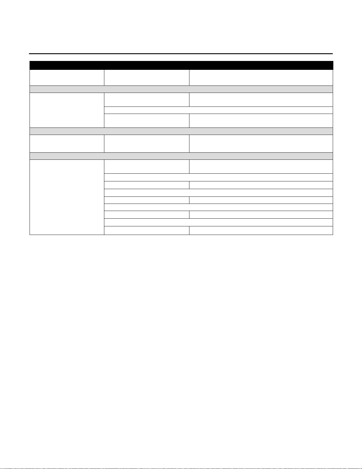
Preventive Maintenance Schedule
ITEM WEEKLY MONTHLY QUARTERLY BI-ANNUAL ANNUAL
DISPLAY CONSOLE ASSEMBLEY
Hardware Inspect
Overlay Clean Inspect
Emergency
Switch/Key
Hardware Inspect
Handlebar Inspect
Side Hand Rails Inspect
Hardware Inspect
Motor Cover Clean
Drive Belt Inspect
Front Roller Inspect
Rear Roller Inspect
Clean Inspect
HANDLEBAR ASSEMBLY
FRAME ASSEMBLY
3
Page 45

Life Fitness Sport and Essential Consumer Treadmills
UNPACKGING INSTRUCTIONS
1. Remove all banding from the corrugated shipping container. Carefully lift the top of the box (A) up and off the
base tray (B) and over the treadmill (C).
2. Tear or cut the front corners of the base tray (B) and fold down the front flap of the base tray.
3. Lift and remove the front end support (D). Remove the ship kit box (E) from the treadmill deck and set aside.
Remove the back end support (F).
4. Remove the plastic wrap from the treadmill.
5. Carefully lift the rear of the treadmill and slowly roll the unit forward off the base tray.
NOTE: BE SURE NOT TO DAMAGE THE LINE CORD WHEN MOVING THE TREADMILL OFF OF THE BASE
TRAY.
6. Follow the Assembly Instructions included in the parts bag to complete the assembly of your treadmill.
4
Page 46

Life Fitness Sport and Essential Consumer Treadmills
INSALLATION INSTRUCTIONS
IMPORTANT SAFETY INSTRUCTIONS!
DON NOT position the rear of the treadmill within 6 feet (2 meter) of the nearest obstruction. The sides of the
treadmill should maintain a minimum clearance of 8 inches (20 cm) from the nearest treadmill or other obstruction.
DO NOT locate the treadmill outdoors, near swimming pools, or in areas of high humidity.
DO verify the contents of the delivery carton against the accompanying parts listing prior to setting the cartons
and shipping material aside. If any parts are missing, contact Life Fitness Customer Support Services at the
number listed on the back page of this assembly instruction booklet.
Save the shipping cartons in case of return.
DO read the entire Operation Manual prior to attempting to operate this machine, as this is essential for proper
use. The Manual explains how to properly use the treadmill and helps you to design an aerobic workout tailored to
your personal fitness needs or requirements.
5
Page 47

Life Fitness Sport and Essential Consumer Treadmills
INSALLATION INSTRUCTIONS
TOOLS REQUIRED FOR ASSEMBLEY…6mm Allen Key (provided)
PARTS DESCRIPTION
CONSOLE
1
52436
RIGHT UPRIGHT POST
2
MOUNTING BOLT (SHORT)
3
SC10815 M8x15mm
RIGHT UPRIGHT POST SUPPORT BRACKET
4
53432
STAR WASHER
5
W308008
LEFT UPRIGHT POST SUPPORT BRACKET
6
53433
LEFT UPRIGHT POST
7
MOUNTING BOLT (LONG)
8
SC40855 M8x55mm
HORIZONTAL BAR
9
53328
Qty: 1
Qty: 1
Qty: 17
Qty: 1
Qty: 18
Qty: 1
Qty: 1
Qty: 1
Qty: 1
6
Page 48

Life Fitness Sport and Essential Consumer Treadmills
INSALLATION INSTRUCTIONS
7
Page 49

Life Fitness Sport and Essential Consumer Treadmills
INSALLATION INSTRUCTIONS - Continued
Only one tool is required to assemble the treadmill.
This tool is provided along with the bolt pack.
Keep the tool to tension the running belt in the future.
1. ASSEMBLE THE UPRIGHT POSTS (#2 & #7)
Connect the wires (C & D) before you assemble the upright
posts. Locate each upright post (#2 & #7) on each upright
post bracket (A & B). Secure each upright post (#2 & #7) with
two bolts (#3) and two washers (#5).
Secure each side post support bracket (#4 & #6) with four
bolts (#3) and four washers (#5).
NOTE: Do not tighten these bolts (#3) until the horizontal handlebar (#9) and console (#1) have been tightened.
NOTE: Tare care that the cables (C & D) do not get trapped or pinched
NOTE: Use star washer (#5) for each bolt (#3) connection.
.
2. ASSEMBLE THE HORIZONTAL BAR (#9)
One end of the horizontal handlebar (#9) is not covered all the
way with foam grip. Insert the uncovered end of the bar (#9)
into right upright post (#2) first before fitting the other end flush
against left side (#7).
The left side of the horizontal bar ( #9) is secured with th e long
bolt (#8) and the right side is secured with short bolt (#3).
3. NOTE: Do not tighten these bolts (#3) until the console (#1)
has been tightened. ASSEMBLE THE CONSOLE (#1)
Connect the wires (E & F). Then push the console (#1) onto the upright posts (#2 & #7). You may have to
shake the posts (#2 & #7) from side to side to get the console
(#1) to fit.
Once you have the console (#1) in place, secure and tighten
the bolts (#3) on the console (#1).
8
Page 50

Life Fitness Sport and Essential Consumer Treadmills
INSALLATION INSTRUCTIONS
PRE-OPERATION CHECKLIST
! Ensure that all fasteners are tight.
! Make sure the RUNNING BELT is properly tensioned and aligned according to the Operation Manual.
! Check the operation of the STOP switch and tether switch assembly. (See Operation Manual.)
! Confirm the display console is set to English or Metric units. (See Optional Settings ENGIMET in
Operation Manual.)
! Read the entire Operation Manual before using the treadmill.
If you would like to submit a part order, or if you need help tr oubleshooting a problem, we have inc luded, for your
convenience, a FAX form on the following page. Simply mak e a copy (or copies) of the FAX sheet and fill in t he
necessary information. You may FAX us at any tim e, 24 ho urs a day, to either of the numbers shown. A Life Fitnes s
service representative will process your order, or respond to your problem, as quickly as possible.
9
Page 51

Life Fitness Sport and Essential Consumer Treadmills
NOTES
10
Page 52

© 2000 Life Fitness, a divis i on of Brunswick Corporation. All rights reserved. Life Fitness , Lifecycle, and Lifepulse are regi stered trademarks, and Heart
Rate Zone Training and RELY ON IT are tradem arks of Brunswick Corporation. P ol ar i s a registered trademark of Polar Electro, Inc.
Any use of these trademarks without the express written consent of Li fe Fitness or the corresponding c ompanies is forbidden.
Part No. #7414001
January 2003
 Loading...