

Page 1
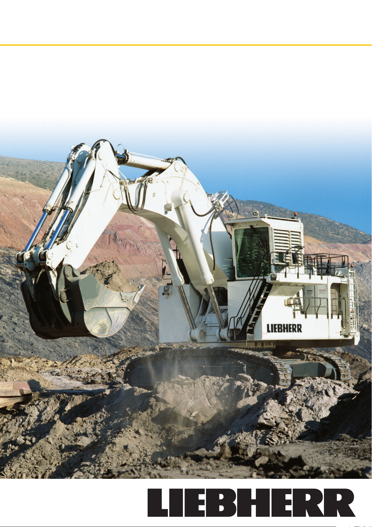
Hydraulic Excavator R 9350 Arctic
Operating Weight
with Backhoe Attachment: 302,000 kg / 665,800 lb
with Shovel Attachment: 310,000 kg / 683,400 lb
Engine Output: 1120 kW / 1500 hp
Bucket Capacity: 15,30 – 18,00 m
Shovel Capacity: 15,30 – 18,00 m3/ 20.0 – 23.5 yd
Operating Temperature: – 40 °C to + 40 °C / – 40 °F to + 104 °F
3
/ 20.0 – 23.5 yd
3
3
Page 2

Technical Data
Engine
1 Cummins diesel engine
Rating per
SAE J 1995
Model
Ty pe
Displacement
Bore/Stroke
Engine cooling system
Air cleaner
Fuel tank
Electrical system
Voltage
Batteries
Alternator
Engine idling
Electronic engine
control system
Option
________________
________________________
__________________________
____________
________________
______________________
________________________
______________________
____________________
__________________
____________________
________________
____________________________
Hydraulic System
Hydraulic pumps
for attachment and
travel drive
Max. flow
Max. hydr. pressure
Hydraulic pump
for swing drive
Max. flow
Max. hydr. pressure
Pump regulation
Hydraulic tank capacity
Hydraulic system
capacity
Hydraulic oil filter
Hydraulic oil cooler
________________
__________________
____________
__________________
______________
__________________________
______________
__________
1500 hp (1120 kW) at 1800 rpm
QSK45
12 cylinder turbocharged V-engine,
after-cooler,
two separate water cooling circuits,
direct injection system
45 l/2745 in
159/190 mm / 6.26/7.48 in
______
fans driven via hydraulic piston motor
3
dry-type air cleaner with pre-cleaner, with
automatic dust ejector, primary and safety
elements
5815 l/1536 gal
24 V
4 (+ 2) x 170 Ah/12 V
24 V/260 Amp
sensor controlled
engine speed sensing over the entire
engine RPM range. Provides integration
of engine with other machine systems
alternate diesel engine or electric motor on
request
4 variable flow axial piston pumps
4 x 754 l/min. / 4 x 199 gpm
____
320 bar/4640 psi
2 reversible swash plate pumps, closedloop circuit
2 x 390 l/min. / 2 x 10³ gpm
____
350 bar/5076 psi
electro-hydraulic,
pressure compensation,
flow compensation,
automatic oil flow optimizer
____
2200 l/581 gal
4200 l/1110 gal
filtration of entire return flow, 1 high
pressure filter for each main pump
2 separate coolers, 2 temperature
controlled fans driven via hydraulic piston
motor
Swing Drive
Hydraulic motor
Swing gear
Swing ring
Swing speed
Swing torque
Swing-Holding brake
________________
______________________
______________________
____________________
__________________
________
Uppercarriage
____________________________
Design
Attachment mounting
Catwalks
________________________
________
Service Flap
____________________________
Design
Quick couplers on request
2 Liebherr axial piston motors
2 Liebherr planetary reduction gears
Liebherr, sealed triple roller swing ring,
internal teeth
0 – 3.7 rpm
1120 kNm/82,607 lbf ft
hydraulically released, maintenance-free,
multi-disc brakes integrated in each swing
gear
torque resistant designed upper frame in
box type construction for superior strength
and durability
parallel longitudinal main girders in boxsection construction
on the left side with a hydraulically driven
access ladder, catwalks in front of the
pumps and in the counterweight, additional
emergency ladder in front of the cab
hydraulically actuated service flap, with
lighting easily accessible from ground level
to allow:
– fuel fast refill
– hydraulic oil refill
– engine oil quick change
– splitterbox oil quick change
– swing gearbox oil quick change
– swing ring teeth grease barrel refilling via
grease filter
– attachment/swing ring bearing grease
barrel refilling via grease filter
– windshield wash water refilling
Hydraulic Controls
Servo circuit
Emergency control
Power distribution
Flow summation
Control functions
Attachment and
swing
Travel
Bottom dump bucket
2 R 9350 Arctic
____________________
________________________
________________________
______
____________
________
independant, electric over hydraulic
proportional controls of each function
via accumulator for all attachment functions with stopped engine
via monoblock control valves with inte grated primary relief valves and flanged on
secondary valves
to attachment and travel drive
proportional via joystick levers
proportional via foot pedals or hand levers
__
proportional via foot pedals
Page 3

Technical Data
Operator’s Cab
____________________________
Design
Operator’s seat
Cabin windows
Heating system/
Air conditioning
Cabin pressurization
Controls
Monitoring
Automatic engine
shut off
Destroking of main
pumps
Safety functions
________________
________________
________________
________
__________________________
______________________
____________________________
____________________________
______________
Noise emission
ISO 6396________________ L
Undercarriage
____________________________
Design
Hydraulic motor
Travel gear
Travel speed
Parking brake
Track components
Track rollers/
Carrier rollers
Automatic track
tensioner
Transport
________________
______________________
____________________
__________________
____________
__________________
________________________
________________________
resiliently mounted, sound insulated,
large windows for all around visibility,
integrated falling object protection FOPS
suspended, body-contoured with shock
absorber, adjustable to operator’s weight
20,5 mm/0.8 in tinted armored glass for
front window and right hand side windows,
all other windows in tinted safety glass,
high pressure windshield-washer system
75 l/20 gal watertank,
steel sun louvers on all windows
1 heating system + air conditioning (double
unit optionally available)
ventilation with filter
joystick levers integrated into armrest of
seat
via LCD-Display, data memory
engine self-controlled shut off
in case of low hydraulic oil level
additional gauges with constant display for:
engine speed, hourmeter, voltmeter, safety
mode for engine speed control and pump
regulation
(inside cab) = 89 dB(A)
pA
with AC/heater 100 % running fans
3-piece undercarriage,
box type structures for center piece and
side frames (stress relieved steel work
component as a standard)
2 axial piston motors per side frame
Liebherr planetary reduction gear
0 – 2,4 – 3,1 km/h / 0 – 1.49 – 1.93 mph
spring engaged, hydraulically pressure
released wet multi-disc brakes for each
travel motor, maintenance-free
D 12, maintenance-free, forged double
grouser pad
9/2
pressurized hydraulic cylinder with accumulator
undercarriage side frames are removable
Central Lubrication System
________________________________
Ty pe
Grease pumps
Capacity
______________________________
Refill
________________
__________________________
Attachment
____________________________
Design
____________________________
Pivots
Hydraulic cylinder
Hydraulic connections
Kinematics
____________
______________________
Lincoln Centromatic lubrication system, for
the entire attachment and swing ring
Lincoln Powermaster pump plus separate
pump for swing ring teeth
200 l/52.8 gal bulk container for attachment
and swing ring, separated 80 l/21 gal bulk
container for swing ring teeth
via the service flap for both containers.
Fill line with grease filters
box-type structure with large steel castings
in all high-stress areas
sealed with double side centering with
1 single floating pin per side,
all bearings with wear resistant steel
bushings,
bolts hardened and chrominium-plated
Liebherr design, all cylinders located in well
protected areas
______
pipes and hoses equipped with SAE splitflange connections
Liebherr parallel face shovel attachment
geometry, backhoe bucket pivoting angle
150°, electronic controlled end-cushioning
R 9350 Arctic 3
Page 4

Arctic Kit
Electrical Preheating prior to Engine
Start
The hydraulic excavator can be preheated with an external electric power
supply (80 kW, 400 V, 50 Hz). The electric power supply must be connected
to the excavator through a connector situated on the cab elevation. The
following heating equipments are installed on the excavator and each heater
is designed to heat a part of the machine:
Electrically driven water
engine preheater units
________
2 preheaters from 4 kW
automatic preheating/warm keeping (own
thermostat) of coolant of diesel engine
Electrically driven warm
air blowers
________________________
6 blowers from 3 kW
automatic warm keeping (blowers with own
thermostat) of the ambient air temperature in
pumps compartment, main valves compart-
ment, cab elevation and engine compartment,
warm keeping of the hydraulic piloting units
and electric boxes
Electrical oil heater units
in the hydraulic tank
______
7 resistors from 2 kW
automatic preheating/warm keeping (own
thermostat) of hydraulic oil in the hydraulic tank
in the splitterbox
__________
2 resistors from 500 W
automatic preheating/warm keeping (own
thermostat) of splitterbox oil
______
in the engine oil pan
4 resistors from 500 W
automatic preheating/warm keeping (own
thermostat) of engine oil
______
in the suction pipes
2 resistors from 500 W
automatic preheating/warm keeping (own
thermostat) of hydraulic oil in the suction pipes
Electrical heating cabin
windows
__________________________
filaments in the windshield and all the side
windows
automatic defrosting of the cabin windows
____
Electrical cabin preheater
1 preheater from 3 kW
automatic preheating/warm keeping (own
thermostat) of the cabin
Heating covers around the
grease containers
______________
automatic preheating/warm keeping (own
thermostat) of the greasing tank
Heating covers around the
batteries
24 V resistor heating
__________________________
__________
automatic preheating/warm keeping (own
thermostat) of batteries
resistors from 20 W and 150 W
automatic heating and drying of electric boxes
and operator’s seat
Two forced circulating
heating system
__________________
2 preheaters from 9 kW
automatic preheating/warm keeping of all
working pumps, slew pumps, fan pumps, slew
Fuel preheater
__________________
motors, drive motors and valves blocs
heat exchanger with warm engine coolant,
preheated fuel at the entry of the engine
Electrical Heating After Engine Start
(without Electrical Supply)
Continuous flushing of swing and travel motors with an additional gear
pump, in order to supply oil at operating temperature even if travel or swing
functions are not actuated.
Continuous preheating fuel with a warm engine coolant heat exchanger.
Insulation
Thermal insulated
components
Closed carbody openings
Snow protection for
engine air filter intake
______________________
____
__________
complete power pack, main control valve
compartment, hydraulic tank module, fuel
tank and cab elevation, battery compartment,
cab roof, floor and walls, grease containers
mechanically adjustable louvers to isolate the
excavator
– in front of engine radiator
– in front of hydraulic radiator
optional air intake from the engine compartment is possible
Central Lubrication System
____________________________
Design
thermal insulated grease containers, large
nominal width for all grease lines, special
injector for cold climate
__________
Heated components
electro thermal wrap around, both grease containers
Features of the Electrical Preheating
System
Electrical system is designed corresponding to europeen standards
400 V/230 V/50 Hz. Optionally the system can be delivered corre spond ing
to CSA standards.
– Different components with CSA approval
– Different tension and frequency 440 V/254 V/60 Hz
Safety IT-System
________________
isolated ground, monitoring of: short circuit,
overload, isolation; system reactions: warning
Battery charge
__________________
24 V board network
Accessory parts
____________
________________
(acoustical/optical), shut down
continuously during standstill
continuous power supply
additional alternator to ensure 100 % lighting
and heating, additional battery pack for
emergency lighting
Steel Construction
The steel structures of the Liebherr standard excavators are good for
–40 °C. Minimum required are Charpy impact values of 27 joule at minimum
ambient temperature.
Liebherr requirements:
for steel plates LH 380
for casting parts
for mining
________________________
________
36 Joule at –40 °C
AOD (Argon Oxygen Decarburizing) or
VLS (Very Low Sufur) steel > 60 Joule at –20 °C
Operator’s Cab
____________________________
Design
Heating system
Controls
__________________________
__________________
increased thermal insulation at walls, roofs
and cab floor
heating capacity adapted to arctic conditions,
windshield and front side windows pre heated
to defrost, and also insulation glass, heated
operator’s seat (minimum temperature inside
the operator’s cab during standstill + 15 °C/
+ 59 °F)
electrical boxes and joysticks equipped with
24 V electrical heating elements
Stand-by Heating Operation
If the machine is turned off for more than one hour and the ambient air
temperature is below – 10 °C, connect the external generator set to start the
heaters (auto-regulated) in order to maintain the excavator in predefined
temperature and to be able to restart quickly.
Heated areas
Heated components
4 R 9350 Arctic
____________________
__________
operator’s cab, cab elevation, valve bank
compartment, engine compartment
engine and splitter box, main, slew, oil cooler,
watercooler pumps, batteries, travel, swing
motors, main valves blocks, electrical boxes
and joysticks, grease pumps and control valves
Additionnal Measures
Low temperature
adapted lubricants
Undercarriage components
in –40 °C version
Uppercarriage components
in –40 °C version
Attachment
____________
________________
________________
______________________
for uppercarriage, for undercarriage
accumulators, track tensioning cylinder,
(standard track roller are good for –40 °C)
splitter box, gear pumps, accumulators,
fan drive motors
use of special low temperature hoses for uppercarriage to attachment and attachment hoses
Page 5

Q
Z
W1
E
DF
L
X1
H2
U
V1
H
H1
K
C
P
A2
A
A1
N
S
G
B
Dimensions
L
K
Q
X
V
H
H1
H2
C
P
W1
W
U
Z
A2
E
DF
A
A1
N
S
G
B
A 5800/19’
mm/ft in
A1 6720/22’ 1”
A2 7400/24’ 3”
C 7800/25’ 7”
D 6395/20’12”
E 6395/20’12”
F 3100/10’ 2”
H 5480/17’12”
H1 6500/21’ 4”
H2 7075/23’ 3”
K 2280/ 7’ 6”
L 6400/21’
”
P 2360/ 7’ 9”
Q 982/ 3’ 3”
S 5000/16’ 5”
U 8334/27’ 4”
Z 10470/34’ 4”
N 850/ 2’ 9”
B 5850/19’ 2”
G 6340/20’10”
V 11800/38’ 9”
W 8100/26’ 7”
W1 8700/28’ 7”
”
X 18450/60’ 6”
mm/ft in
A 5800/19’
A1 6720/22’ 1”
A2 7400/24’ 3”
C 7800/25’ 7”
D 6395/20’12”
E 6395/20’12”
F 3100/10’ 2”
H 5480/17’12”
H1 6500/21’ 4”
H2 7075/23’ 3”
K 2280/ 7’ 6”
L 6400/21’
mm/ft in
”
P 2360/ 7’ 9”
Q 982/ 3’ 3”
S 5000/16’ 5”
mm/ft in
U 8334/27’ 4”
Z 10470/34’ 4”
N 850/ 2’ 9”
B 5850/19’ 2”
G 6340/20’10”
V1 15900/52’20”
W1 7100/23’ 4”
X1 20700/67’11”
”
R 9350 Arctic 5
Page 6

Backhoe Attachment
024681012141618 m
0ft1020304050
0
-2
-4
-6
-8
-10
0
-10
-20
-30
2
4
6
8
10
12
14
16
10
20
30
40
18
m
50
60
ft
60
with Gooseneck Boom 9,30 m/30’6” and Stick 4,20 m/13’8”
Digging Envelope
Max. reach at ground level 16,30 m/53’6”
Max. teeth height 15,40 m/50’6”
Max. dump height 10,20 m/33’6”
Max. digging depth 9,50 m/31’2”
Max. digging force 880 kN ( 89,7 t)/197,832 lbf (197,750 lb)
Max. breakout force 1020 kN (104,0 t)/229,305 lbf (229,280 lb)
Operating Weight
and Ground Pressure
The operating weight includes the basic machine with backhoe
3
attachment and a 18,00 m
/23.5 yd3bucket.
Pad width mm/in 850/34
Weight kg/lb 302000/665,800
2
Ground pressure kg/cm
/psi 2,51/35.27
Bucket
Cutting width SAE mm/in 3400/134
1)
3400/134
Capacity SAE heaped m3/yd315,30/20 17,00/22.2 18,00/23.5
Weight kg/lb 17000/37,480 17790/39,220 18155/40,020
3
Suitable for material up to a specific weight of t/m
/lb/yd32,10/3,570 1,90/3,230 1,80/3,000
Wear kit level II II II
1)
Bucket with delta cutting edge and tooth system Posilok size S 95.
Wear kit level II: For heavy rock, not deteriorated or cracked. Has to be shot to be dug.
Additional buckets on request.
1)
3400/134
1)
6 R 9350 Arctic
Page 7

Shovel Attachment
T
02468101214 m
0ft1020304050
0
-2
-4
0
-10
2
4
6
8
10
12
14
16
m
10
20
30
40
50
ft
17
60
with Shovel Boom 6,75 m/22’2” and Stick 4,20 m/13’8”
Digging Envelope
Max. reach at ground level 13,75 m/45’1”
Max. dump height 11,20 m/36’9”
Max. crowd length 5,20 m/17’1”
Bucket opening width T 2500 mm/98”
Crowd force at ground level 1040 kN (106,0 t)/233,801 lbf (233,690 lb)
Max. crowd force 1300 kN (132,5 t)/292,252 lbf (292,110 lb)
Max. breakout force 1060 kN (108,0 t)/238,297 lbf (238,100 lb)
Operating Weight
and Ground Pressure
The operating weight includes the basic machine with shovel attach-
3
ment and a 18,00 m
/23.5 yd3bucket.
Pad width mm/in 850/34
Weight kg/lb 310000/683,400
2
Ground pressure kg/cm
/psi 2,58/36.69
Bottom Dump Bucket
Cutting width SAE mm/in 4100/161
1)
4100/161
Capacity SAE heaped m3/yd315,30/20 17,00/22.2 18,00/23.5
Weight kg/lb 30000/66,140 31000/68,340 31500/69,450
Suitable for material up to a specific weight of t/m
3
/lb/yd32,10/3,570 1,90/3,230 1,80/3,000
Wear kit level II II II
1)
Bottom dump bucket with delta cutting edge and tooth system Posilok size S 95.
Wear kit level II: For heavy rock, not deteriorated or cracked. Has to be shot to be dug.
Additional bottom dump buckets on request.
1)
4100/161
1)
R 9350 Arctic 7
Page 8

Component Dimensions and Weights
L
H
L
H
L
H
L
H
H1
H2
B
B1
L
H
L
H
Cab
L Length mm/ft in 3600/11’10”
H Height mm/ft in 2900/ 9’ 6”
Width mm/ft in 2315/ 7’ 7”
Weight kg/lb 3500/7,720
Cab Elevation
L Length mm/ft in 2415/7’11”
H Height mm/ft in 2550/8’ 4”
Width mm/ft in 2550/8’ 4”
Weight kg/lb 3500/7,720
Fuel Tank
L Length mm/ft in 2970/9’9”
H Height mm/ft in 2930/9’7”
Width mm/ft in 2130/7’
Weight kg/lb 3700/8,160
”
Powerplant
L Length mm/ft in 4800/15’ 9”
H Height mm/ft in 3000/ 9’10”
H1Height mm/ft in 3700/12’ 2”
H2Height mm/ft in 4400/14’ 5”
B Width mm/ft in 2200/ 7’ 3”
B1 Width mm/ft in 2950/ 9’ 8”
Weight kg/lb 17500/38,580
Rotation Deck (with swing ring, swing gears,
control valve bracket and service flap)
L Length mm/ft in 8100/26’7”
H Height mm/ft in 3882/12’8”
Width mm/ft in 3700/12’2”
Weight kg/lb 42700/94,140
Counterweight
L Length mm/ft in 1100/ 3’7”
H Height mm/ft in 3250/10’8”
Width mm/ft in 6000/19’8”
Weight kg/lb 25320/55,820
8 R 9350 Arctic
Arctic Kit
Weight kg/lb 3000/6,610
Page 9

Component Dimensions and Weights
L
H
L
H
L
H
L
H
L
H
L
H
Hydraulic Tank
L Length mm/ft in 4920/16’2”
H Height mm/ft in 2900/ 9’6”
Width mm/ft in 1820/ 6’
Weight kg/lb 7870/17,350
Hydraulic Oil
Weight kg/lb 2940/6,500
Small Pieces
L Length mm/ft in 4500/14’9”
H Height mm/ft in 2600/ 8’6”
Width mm/ft in 2000/ 6’7”
Weight kg/lb 4500/9,920
”
Catwalk Box Left
L Length mm/ft in 2140/7’ ”
H Height mm/ft in 2960/9’9”
Width mm/ft in 700/2’4”
Weight kg/lb 1900/4,190
Catwalk Box Right
L Length mm/ft in 2120/6’11”
H Height mm/ft in 2960/9’ 9”
Width mm/ft in 950/3’ 1”
Weight kg/lb 800/1,760
Side Frame (two)
L Length mm/ft in 8334/27’ 4”
H Height mm/ft in 2360/ 7’ 9”
Width over
travel drive mm/ft in 2055/ 6’ 9”
Width without
travel drive mm/ft in 1485/ 4’10”
Weight kg/lb 2 x 43350/2 x 95,570
Undercarriage Central Girder
L Length mm/ft in 3670/12’ ”
H Height mm/ft in 2482/ 8’2”
Width mm/ft in 3670/ 8’9”
Weight kg/lb 25600/56,440
R 9350 Arctic 9
Page 10

Component Dimensions and Weights
L
H
L
L
H
L
L
H
L
L
H
Shovel Boom
L Length mm/ft in 7250/23’ 9”
H Height mm/ft in 2350/ 7’ 9”
Width mm/ft in 2400/ 7’10”
Weight kg/lb 25200/55,560
Hoist Cylinder (two)
for Shovel Attachment
L Length mm/ft in 4690/15’ 5”
Ø Diameter mm/in 550/
Weight kg/lb 2 x 3510/2 x 7,700
Shovel Stick
L Length mm/ft in 4700/15’5”
H Height mm/ft in 1900/ 6’3”
Width mm/ft in 2250/ 7’5”
Weight kg/lb 12750/28,110
’22”
Crowd Cylinder (two)
L Length mm/ft in 3350/11’ 0”
Ø Diameter mm/in 400/
Weight kg/lb 2 x 1470/2 x 3,240
Bottom Dump
Bucket 20.0 yd
L Length mm/ft in 3700/12’2” 3900/12’10” 4200/13’9”
H Height mm/ft in 3800/12’6” 3800/12’ 6” 3800/12’6”
Width mm/ft in 4200/13’9” 4200/13’ 9” 4200/13’9”
Weight kg/lb
15,30 m3/ 17,00 m3/ 18,00 m3/
30000/66,000 31000/68,340 31500/69,450
3
22.2 yd
3
’15”
23.5 yd
Bucket Tilt Cylinder (two)
L Length mm/ft in 3950/13’ 0”
Ø Diameter mm/in 450/
Weight kg/lb 2 x 2015/2 x 4,440
’18”
Gooseneck Boom
with Stick Cylinders
L Length mm/ft in 9800/32’ 2”
H Height mm/ft in 3900/12’10”
Width mm/ft in 2200/ 7’ 3”
Weight kg/lb 30700/67,682
3
10 R 9350 Arctic
Page 11

Component Dimensions and Weights
L
L
H
L
H
Hoist Cylinders (two)
for Backhoe Attachment
L Length mm/ft in 4680/15’ 4”
Ø Diameter mm/in 550/
Weight kg/lb 2 x 3800/2 x 8,380
Stick with Bucket Cylinders
L Length mm/ft in 6000/19’ 8”
H Height mm/ft in 2400/ 7’10”
Width mm/ft in 1750/ 5’ 9”
Weight kg/lb 18940/41,670
’22”
Backhoe Bucket
L Length mm/ft in 4000/13’ 1” 4000/13’1” 4200/13’9”
H Height mm/ft in 2700/ 8’10” 2800/ 9’2” 2800/ 9’2”
Width mm/ft in 3500/11’ 6” 3500/11’6” 3500/11’6”
Weight kg/lb
15,30 m3/ 17,00 m3/ 18,00 m3/
17000/37,480 17790/39,220 18155/40,020
20.0 yd
3
22.2 yd
3
23.5 yd
3
All illustrations and data may differ from standard equipment. Subject to change without notice. All indicated loads are based in accordance with ISO 9248.
R 9350 Arctic 11
Page 12

The Liebherr Group of Companies
Wide product range
The Liebherr Group is one of the largest construction
equipment manufacturers in the world. Liebherr’s highvalue products and services enjoy a high reputation in
many other fields, too. The wide range includes domes tic appliances, aerospace and transportation systems,
machine tools and maritime cranes.
Exceptional customer benefit
Every product line provides a complete range of models
in many different versions. With both its technical excel lence and acknowledged quality, Liebherr products offer
a maximum of customer benefits in practical application.
State-of-the-art technology
To provide consistent, top quality products, Liebherr
attaches great importance to each product area, its
components and core technologies. Important modules
and components are developed and manu factured inhouse, for instance the entire drive and control techno logy for construction equipment.
Worldwide and independent
Hans Liebherr founded the Liebherr family company in
1949. Since that time, the enterprise has steadily grown to
a Group of 100 companies with over 30,000 employees
located on all continents. The corporate headquarters of
the Group is Liebherr-International AG in Bulle, Switzerland.
The Liebherr family is the sole owner of the com pany.
www.liebherr.com
RG-BK-RP LFR/SP 10440689-03.08
Liebherr-France SAS
2, avenue Joseph Rey, B.P. 90287, F-68005 Colmar Cedex
콯 +33 389 21 30 30, Fax +33 389 21 37 93
www.liebherr.com, E-Mail: info.lfr@liebherr.com
 Loading...