

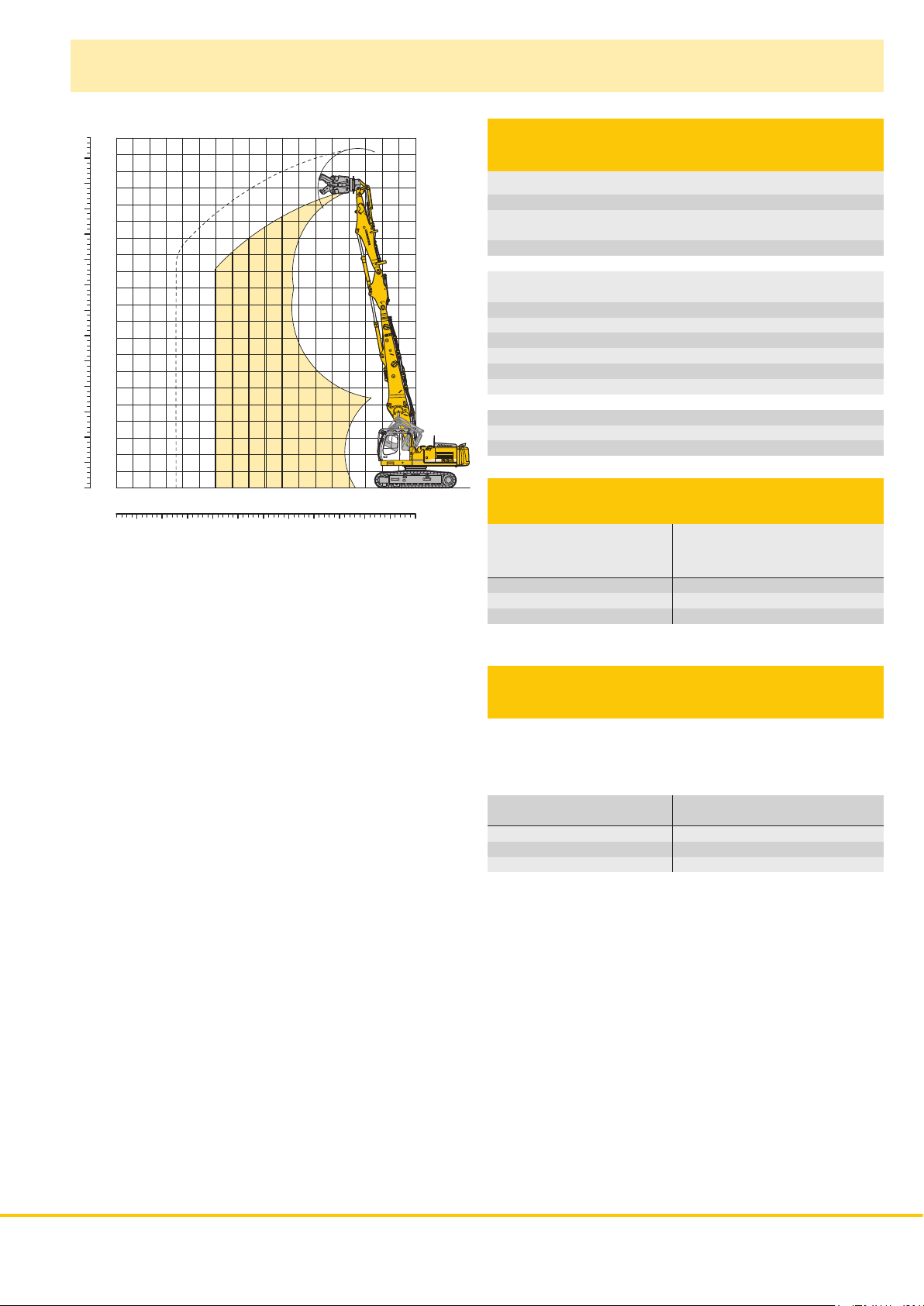
Page 1
Crawler Excavator R 934 C
litronic
`
Attachment Information
Liebherr Crawler Excavator
with Demolition Attachment
Page 2
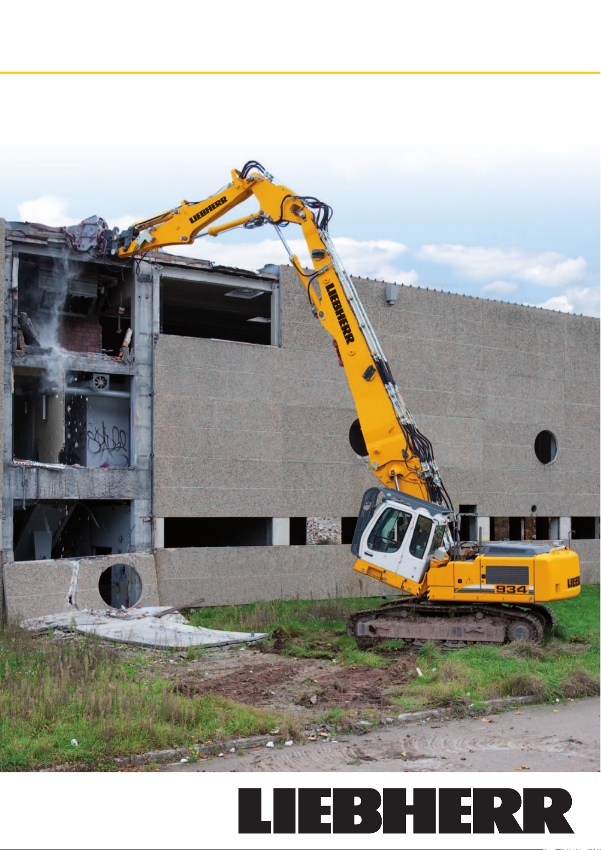
Demolition Attachment 19.50 m
ft
m
23
75
22
70
21
20
65
19
60
18
17
55
16
50
15
14
45
13
40
12
11
35
10
30
9
8
25
7
20
6
5
15
4
10
3
2
5
1
0
0
0 m246810
1357911131517 12141618
0 ft102030
51525354555 4050
To order a complete machine
you need the following
Cab tiltable 30°
Hydraulic control for rotary drive
Hydraulic control for hammer/shears with Tool-Control and LiebherrDemolition-Control (LDC)
Hoist cylinders with regeneration plus and load holding valves
For demolition application, following additional items
are also required:
Demolition boom 7.50 m
Intermediate boom 2.10 m
Demolition stick 5.20 m with linkage 922 Li
Tool (backhoe bucket, demolition shears, concrete nibblers, etc.)
Storage racks for demolition attachment
Integral protection grid FOPS
Optional
Integral protection grid for cab on tilting device FOPS
Hydraulic accessory for quick change adapter on basic boom
Reach Limitation
Demolition boom 7.50 m
+ Intermediate boom
+ Demolition stick 5.20 m Tool weight* in t
NLC-Undercarriage 2.00 1.75 1.50 1.00 – –
LC-Undercarriage 2.25 2.00 1.75 1.25 – –
VH-HD-Undercarriage 2.50 2.50 2.50 2.00 1.75 1.50
* included quick change adapter, adapter plate and tool
8 m 9 m 10 m 11 m 12 m 13 m
Operating Weight
and Ground Pressure
Operating weight includes basic machine with heavy duty counterweight 7.5 t (6.5 t for the VH-HD-Undercarriage), the cab tiltable 30°,
demoli tion boom 7.50 m, intermediate boom, demolition stick 5.20 m
standard and working tool 1.5 t.
Undercarriage
Pad width mm
Weight kg
Ground pressure kg/cm2
NLC LC VH-HD
600 750 600 750 600
41,350 42,300 41,450 42,400 47,550
0.80 0.65 0.80 0.65 0.90
2 R 934 C Litronic Demolition Attachment
Page 3
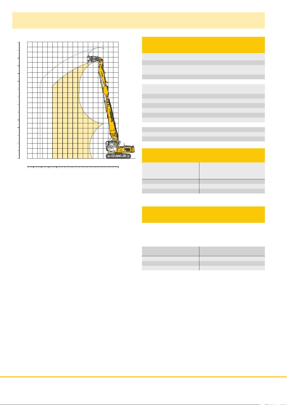
Demolition Attachment 18.00 m
ft
m
21
20
65
19
60
18
17
55
16
50
15
14
45
13
40
12
11
35
10
30
9
8
25
7
20
6
5
15
4
10
3
2
5
1
0
0
0 m246810
1357911131517 12141618
0 ft102030
51525354555 4050
To order a complete machine
you need the following
Cab tiltable 30°
Hydraulic control for rotary drive
Hydraulic control for hammer/shears with Tool-Control and LiebherrDemolition-Control (LDC)
Hoist cylinders with regeneration plus and load holding valves
For demolition application, following additional items
are also required:
Demolition boom 6.00 m
Intermediate boom 2.10 m
Demolition stick 5.20 m with linkage 922 Li
Tool (backhoe bucket, demolition shears, concrete nibblers, etc.)
Storage racks for demolition attachment
Integral protection grid FOPS
Optional
Integral protection grid for cab on tilting device FOPS
Hydraulic accessory for quick change adapter on basic boom
Reach Limitation
Demolition boom 6.00 m
+ Intermediate boom
+ Demolition stick 5.20 m Tool weight* in t
NLC-Undercarriage 2.50 2.00 1.50 1.25 –
LC-Undercarriage 2.50 2.25 1.75 1.50 –
VH-HD-Undercarriage 2.50 2.50 2.50 2.00 1.50
* included quick change adapter, adapter plate and tool
8 m 9 m 10 m 11 m 12 m
Operating Weight
and Ground Pressure
Operating weight includes basic machine with heavy duty counterweight 7.5 t (6.5 t for the VH-HD-Undercarriage), the cab tiltable 30°,
demoli tion boom 6.00 m, intermediate boom, demolition stick 5.20 m
standard and working tool 1.5 t.
Undercarriage
Pad width mm
Weight kg
Ground pressure kg/cm2
NLC LC VH-HD
600 750 600 750 600
40,900 41,850 41,000 41,950 47,100
0.79 0.64 0.79 0.64 0.89
R 934 C Litronic Demolition Attachment 3
Page 4

Backhoe Attachment
with Main Boom 4.25 m
45
40
35
30
25
15
-10
-15
-20
35
30
25
20
15
10
-10
-15
-20
mft
14
12
10
8
20
6
4
10
2
5
0
0
-5
-2
-4
-6
1214
1
2
3
4
0 m246810
0 f t102030
515253545 40
For backhoe application, following
items are required
Main boom 4.25 m
Stick 2.00 m, 2.50 m, 3.10 m, 3.90 m
Storage racks for backhoe attachment
Optional
Hydraulic lines AHS * for main boom 4.25 m
Hydraulic lines AHS * for stick 2.00 m, 2.50 m, 3.10 m, 3.90 m
Hydraulic lines rotary drive for main boom 4.25 m
Hydraulic lines rotary drive for stick 2.00 m, 2.50 m, 3.10 m, 3.90 m
Backhoe bucket – as required
* AHS = hydraulic control for hydraulic accessory
Digging Envelope Main Boom
pinned in upper (in lower) bearing 1 2 3 4
Stick lengths m
Max. digging depth m
Max. reach at ground level m
Max. dump height m
Max. teeth height m
2.00 2.50 3.10 3.90
3.28 ( 4.82) 3.65 ( 5.19) 4.25 ( 5.79) 5.05 ( 6.59)
10.75 (10.23) 11.10 (10.55) 11.69 (11.11) 12.47 (11.87)
8.47 ( 6.52) 8.99 ( 6.90) 9.44 ( 7.12) 10.04 ( 7.42)
12.23 (10.08) 12.47 (10.27) 12.91 (10.52) 13.49 (10.84)
Digging Forces
mf t
10
8
6
4
2
5
0
0
-5
-2
-4
-6
1214
1
2
3
4
0 m246810
0 ft102030
51525354 5 40
with Quick Change Adapter 1 2 3 4
Digging force ISO kN 161 137 119 102
t 16.4 13.9 12.1 10.4
Breakout force ISO kN 187 155 155 155
t 19.1 15.8 15.8 15.8
without Quick Change Adapter
Digging force ISO kN 170 146 126 106
t 17.3 14.9 12.8 10.8
Breakout force ISO kN 213 184 184 184
t 22.1 18.8 18.8 18.8
Max. breakout force with ripper bucket 264 kN (27.9 t)
Operating Weight
and Ground Pressure
Operating weight includes basic machine with heavy duty counterweight 7.5 t (6.5 t for the
VH-HD-Undercarriage), the cab tiltable 30°, main boom 4.25 m, stick 2.50 m, quick change
adapter 66 and backhoe bucket 1.00 m
Undercarriage NLC LC VH-HD
Pad width mm 600 750 600 750 600
Weight kg 38,800 39,750 38,900 39,850 45,000
Ground pressure kg/cm
3
(960 kg).
2
0.75 0.61 0.75 0.61 0.85
Buckets Machine stability per ISO 10567* (75 % of tipping capacity)
NLC-Undercarriage LC-Undercarriage VH-HD-Undercarriage
Stick length (m) Stick length (m) Stick length (m)
Cutting
width
Capacity
ISO 7451
2.00 2.50 3.10 3.90 2.00 2.50 3.10 3.90 2.00 2.50 3.10 3.90
mm m
1)
1,250
1.25 1,070
1)
1,400
1.45 1,140
1)
1,550
1.60 1,210
2)
1,250
1.25 1,090
2)
1,400
1.45 1,160
2)
1,550
1.60 1,230
1) 3)
1,200
1.25 1,280
1) 3)
1,350
1.50 1,370
1) 3)
1,500
1.75 1,460
1) 3)
1,650
2.00 1,580
2) 3)
1,200
1.25 1,240
2) 3)
1,350
1.50 1,330
2) 3)
1,500
1.75 1,420
2) 3)
1,650
2.00 1,540
* Indicated loads are based on ISO 10567 max. stick length, lifted 360° on firm
1)
Bucket without quick change adapter with teeth Z 50 2) Bucket with quick change adapter with teeth Z 50 3) Bucket R 944 C lit ron ic` with teeth Z 50
Other backhoes available on request
Max. material weight
4 R 934 C Litronic Demolition Attachment
3
kg
Weight
Y
v
v
v
v
v
v
Y
V
y
v
Y
V
y
v
= ≤ 1.8 t/m3,
Y
Y
V
Y
Y
V
v
v
v
v
v
v
v
v
V
= ≤ 1.5 t/m3,
Y
V
y
Y
V
y
v
v
v
v
v
v
v
v
y
= ≤ 1.2 t/m3,
V
y
v
V
y
v
v
v
v
v
v
v
v
v
v
v
v
v
v
v
Y
Y
V
y
Y
Y
V
y
v
= not authorized
Y
Y
Y
Y
Y
Y
v
v
v
v
v
v
v
v
Y
Y
V
Y
Y
V
v
v
v
v
v
v
v
v
Y v Y Y Y
V v Y Y V
y v Y Y y
Y v Y Y Y
y v Y Y y
v v Y V v
v Y v v v
v Y v v v
v Y v v v
v Y v v v
v Y v v v
v Y v v v
v Y v v v
v Y v v v
Page 5

Lift Capacities
with Main Boom 4.25 m
Stick 2.00 m
Height Under- Radius of load from centerline of machine (m)
(m) carriage
NLC
LC
10.5
VH-HD
NLC
LC
9.0
VH-HD
NLC
LC
7.5
VH-HD
NLC
LC
6.0
VH-HD
NLC
LC
4.5
VH-HD
NLC
LC
3.0
VH-HD
NLC
LC
1.5
VH-HD
NLC
LC
0
VH-HD
NLC
LC
– 1.5
VH-HD
NLC
LC
– 3.0
VH-HD
NLC
LC
– 4.5
VH-HD
3.0 4.5 6.0 7.5 9.0 10.5
8.4# ( 8.4#)
8.4# ( 8.4#)
8.5# ( 8.5#)
8.6 (10.0#) 5.7 ( 7.7#)
9.3 (10.0#) 6.2 ( 7.7#)
10.0# (10.0#) 7.8# ( 7.8#)
12.7 (14.0#) 8.0 (10.9#) 5.5 ( 9.2#)
14.0# (14.0#) 8.8 (10.9#) 6.0 ( 9.2#)
14.1# (14.1#) 10.9# (10.9#) 8.6 ( 9.2#)
7.2 (11.8#) 5.1 ( 9.2 ) 3.7 (6.8 )
8.0 (11.8#) 5.7 ( 9.2 ) 4.1 (6.8 )
11.5 (11.9#) 8.2 ( 9.6#) 6.1 (7.6#)
6.5 (12.3 ) 4.8 ( 8.7 ) 3.6 (6.6 )
7.2 (12.3 ) 5.3 ( 8.8 ) 4.0 (6.6 )
10.7 (12.7#) 7.8 (10.0#) 5.9 (7.8 )
6.0 (11.7 ) 4.5 ( 8.4 ) 3.4 (6.4 )
6.8 (11.8 ) 5.0 ( 8.4 ) 3.8 (6.5 )
10.3 (13.0#) 7.5 (10.0 ) 5.8 (7.7 )
5.9 (11.6 ) 4.3 ( 8.3 ) 3.4 (6.4 )
6.6 (11.6 ) 4.8 ( 8.3 ) 3.8 (6.4 )
10.1 (12.5#) 7.3 ( 9.8 ) 5.7 (7.6 )
6.0 (11.3#) 4.4 ( 8.3 )
6.7 (11.3#) 4.9 ( 8.3 )
10.2 (11.2#) 7.4 ( 9.0#)
Stick 2.50 m
Height Under- Radius of load from centerline of machine (m)
(m) carriage
NLC
LC
10.5
NLC
LC
9.0
NLC
LC
7.5
NLC
LC
6.0
NLC
LC
4.5
NLC
LC
3.0
NLC
LC
1.5
NLC
LC
0
NLC
LC
– 1.5
NLC
LC
– 3.0
NLC
LC
– 4.5
VH-HD
VH-HD
VH-HD
VH-HD
VH-HD
VH-HD
VH-HD
VH-HD
VH-HD
VH-HD
VH-HD
3.0 4.5 6.0 7.5 9.0 10.5
7.0# ( 7.0#)
7.0# ( 7.0#)
7.1# ( 7.1#)
7.9# ( 7.9#) 6.0 ( 6.8#)
7.9# ( 7.9#) 6.6 ( 6.8#)
8.0# ( 8.0#) 6.9# ( 6.9#)
11.2# (11.2#) 8.5 ( 9.9#) 5.8 ( 8.5#) 4.2 (4.7#)
11.2# (11.2#) 9.2 ( 9.9#) 6.4 ( 8.5#) 4.6 (4.7#)
11.6# (11.6#) 10.0# (10.0#) 8.6# ( 8.6#) 4.9# (4.9#)
11.7 (15.9#) 7.7 (11.8#) 5.5 ( 9.5 ) 4.0 (7.1 )
13.0 (15.9#) 8.5 (11.8#) 6.0 ( 9.6 ) 4.4 (7.1 )
16.0# (16.0#) 11.8# (11.8#) 8.5 ( 9.7#) 6.4 (7.3#)
7.7# ( 7.7#) 7.0 (12.8#) 5.1 ( 9.1 ) 3.9 (6.9 )
7.7# ( 7.7#) 7.7 (12.8#) 5.6 ( 9.1 ) 4.3 (6.9 )
11.2 (12.8#) 8.1 (10.2#) 6.2 (8.1 )
6.4 (12.2 ) 4.8 ( 8.7 ) 3.7 (6.7 )
7.2 (12.2 ) 5.3 ( 8.8 ) 4.1 (6.7 )
10.7 (13.3#) 7.8 (10.3 ) 6.0 (7.9 )
8.6# ( 8.6#) 6.2 (11.9 ) 4.6 ( 8.5 ) 3.6 (6.6 )
8.6# ( 8.6#) 6.9 (12.0 ) 5.1 ( 8.6 ) 4.0 (6.6 )
8.7# ( 8.7#) 10.4 (13.1#) 7.6 (10.1 ) 5.9 (7.8 )
6.2 (11.9 ) 4.6 ( 8.5 ) 3.6 (6.6 )
6.9 (12.0 ) 5.1 ( 8.5 ) 4.0 (6.7 )
10.5 (12.1#) 7.6 ( 9.6#) 6.0 (7.4#)
Stick 3.10 m
Height Under- Radius of load from centerline of machine (m)
(m) carriage
NLC
LC
10.5
VH-HD
NLC
LC
9.0
VH-HD
NLC
LC
7.5
VH-HD
NLC
LC
6.0
VH-HD
NLC
LC
4.5
VH-HD
NLC
LC
3.0
VH-HD
NLC
LC
1.5
VH-HD
NLC
LC
0
VH-HD
NLC
LC
– 1.5
VH-HD
NLC
LC
– 3.0
VH-HD
NLC
LC
– 4.5
VH-HD
3.0 4.5 6.0 7.5 9.0 10.5
4.8# ( 4.8#)
4.8# ( 4.8#)
4.9# ( 4.9#)
4.7# ( 4.7#)
4.7# ( 4.7#)
4.8# ( 4.8#)
6.2# ( 6.2#) 6.0# ( 6.0#)
6.2# ( 6.2#) 6.0# ( 6.0#)
6.3# ( 6.3#) 6.0# ( 6.0#) 3.5# (3.5#)
7.3# ( 7.3#) 6.0 ( 6.9#) 4.3 (5.5#)
7.3# ( 7.3#) 6.5 ( 6.9#) 4.7 (5.5#)
7.4# ( 7.4#) 7.0# ( 7.0#) 5.6# (5.6#)
12.4 (14.8#) 8.0 (11.2#) 5.6 ( 8.9#) 4.1 (6.8#)
13.7 (14.8#) 8.7 (11.2#) 6.1 ( 8.9#) 4.5 (6.8#)
14.9# (14.9#) 11.2# (11.2#) 8.7 ( 9.0#) 6.5 (6.9#)
10.6 (15.3#) 7.2 (12.3#) 5.2 ( 9.2 ) 3.9 (6.9 )
11.8 (15.3#) 7.9 (12.3#) 5.7 ( 9.2 ) 4.3 (6.9 )
14.5# (14.5#) 11.5 (12.3#) 8.2 ( 9.8#) 6.2 (8.1 )
8.3# ( 8.3#) 6.5 (12.3 ) 4.8 ( 8.8 ) 3.7 (6.7 )
8.3# ( 8.3#) 7.3 (12.3 ) 5.3 ( 8.8 ) 4.1 (6.7 )
8.2# ( 8.2#) 10.8 (13.1#) 7.8 (10.2#) 6.0 (7.9 )
9.2# ( 9.2#) 6.2 (11.9 ) 4.6 ( 8.5 ) 3.5 (6.5 )
9.2# ( 9.2#) 6.9 (11.9 ) 5.1 ( 8.5 ) 3.9 (6.5 )
9.3# ( 9.3#) 10.4 (13.2#) 7.6 (10.1 ) 5.9 (7.7 )
9.3 (12.3#) 6.1 (11.8 ) 4.5 ( 8.4 ) 3.5 (6.5 )
10.5 (12.3#) 6.8 (11.8 ) 5.0 ( 8.4 ) 3.9 (6.5 )
12.5# (12.5#) 10.3 (12.5#) 7.5 ( 9.9#) 5.9 (7.7 )
4.5 ( 8.5 )
5.1 ( 8.5 )
Stick 3.90 m
Height Under- Radius of load from centerline of machine (m)
(m) carriage
NLC
LC
10.5
VH-HD
NLC
LC
9.0
VH-HD
NLC
LC
7.5
VH-HD
NLC
LC
6.0
VH-HD
NLC
LC
4.5
VH-HD
NLC
LC
3.0
VH-HD
NLC
LC
1.5
VH-HD
NLC
LC
0
VH-HD
NLC
LC
– 1.5
VH-HD
NLC
LC
– 3.0
VH-HD
NLC
LC
– 4.5
VH-HD
3.0 4.5 6.0 7.5 9.0 10.5
4.5# ( 4.5#)
4.5# ( 4.5#)
3.2# ( 3.2#)
4.8# ( 4.8#) 4.2# (4.2#)
4.8# ( 4.8#) 4.2# (4.2#)
4.5# ( 4.5#)
5.1# ( 5.1#) 5.3# ( 5.3#) 4.4 (4.9#) 2.8# (2.8#)
5.1# ( 5.1#) 5.3# ( 5.3#) 4.8 (4.9#) 2.8# (2.8#)
4.8# ( 4.8#) 4.2# (4.2#)
8.3# ( 8.3#) 7.2# ( 7.2#) 5.8 ( 6.5#) 4.2 (5.7#) 3.1 (4.0#)
8.3# ( 8.3#) 7.2# ( 7.2#) 6.3 ( 6.5#) 4.6 (5.7#) 3.4 (4.0#)
5.2# ( 5.2#) 5.3# ( 5.3#) 4.9# (4.9#) 2.8# (2.8#)
11.4 (15.8#) 7.5 (11.6#) 5.3 ( 9.3#) 3.9 (7.0#) 3.0 (4.7#)
12.7 (15.8#) 8.3 (11.6#) 5.9 ( 9.3#) 4.4 (7.0#) 3.3 (4.7#)
17.7# (17.7#) 8.7# ( 8.7#) 7.3# ( 7.3#) 6.6# ( 6.6#) 5.7# (5.7#) 4.0# (4.0#)
10.0 (11.9#) 6.7 (12.6 ) 4.9 ( 8.9 ) 3.7 (6.7 ) 2.9 (5.2#)
11.2 (11.9#) 7.5 (12.6 ) 5.4 ( 8.9 ) 4.1 (6.7 ) 3.2 (5.2#)
15.9# (15.9#) 11.6# (11.6#) 8.4 ( 9.3#) 6.3 (7.0#) 4.7# (4.7#)
3.4# ( 3.4#) 9.3 (10.0#) 6.2 (12.0 ) 4.6 ( 8.5 ) 3.5 (6.5 ) 2.8 (5.2 )
3.4# ( 3.4#) 10.0# (10.0#) 7.0 (12.0 ) 5.1 ( 8.6 ) 3.9 (6.5 ) 3.1 (5.2 )
11.7# (11.7#) 11.0 (12.6#) 7.9 ( 9.9#) 6.0 (7.9 ) 4.8 (5.2#)
9.1 (11.5#) 6.0 (11.7 ) 4.4 ( 8.3 ) 3.4 (6.4 ) 2.8 (4.0#)
10.3 (11.5#) 6.7 (11.7 ) 4.9 ( 8.4 ) 3.8 (6.4 ) 3.1 (4.0#)
3.5# ( 3.5#) 10.0# (10.0#) 10.5 (13.1#) 7.6 (10.1 ) 5.8 (7.7 ) 4.7 (5.2#)
9.3 (14.9#) 6.0 (11.7 ) 4.4 ( 8.3 ) 3.4 (6.4 )
10.5 (14.9#) 6.7 (11.7 ) 4.9 ( 8.3 ) 3.8 (6.4 )
11.6# (11.6#) 10.2 (12.8#) 7.4 ( 9.9 ) 5.7 (7.6 ) 3.9# (3.9#)
10.2 (11.9#) 7.4 ( 9.3#) 5.8 (7.3#)
The lift capacities on the load hook of the Liebherr quick change adapter 66 without attachment are stated in metric tonnes (t), and can be lifted 360° on firm, level
supporting surface. Values quoted in brackets are valid for the undercarriage when in longitudinal position. Capacities are valid for 600 mm wide triple grouser pads.
Indicated loads are based on ISO 10567 standard and do not exceed 75 % of tipping or 87 % of hydraulic capacity (indicated via #). Maximum load for the quick
change adapter’s load hook is 12 t. Without quick change adapter the lift capacities will increase by 330 kg/450 kg*, without bucket cylinder, link and lever they
increase by an additional 410 kg/590 kg*. Lifting capacity of the excavator is limited by machine stability, hydraulic capacity and maximum permissible load of the
load hook.
According to European Standard, EN 474-5: In the European Union excavators have to be equipped with an overload warning device, a load diagram and automatic
check valves on the hoist cylinders, when they are used for lifting operations which require the use of lifting accessories.
* capacities only for stick 2.00 m
R 934 C Litronic Demolition Attachment 5
Page 6

Dimensions
E
D
A
W
V
X
NLC mm LC mm VH-HD mm
A 3,050 3,050 3,050
C 3,440 3,440 3,500
D 3,236 3,236 3,145
E 3,236 3,236 3,145
H 2,590 2,590 2,650
K 1,150 1,150 1,210
L 4,000 4,000 4,100
P 1,046 1,046 1,140
Q 496 496 437
U 4,920 4,920 5,030
S 2,390 2,590 2,300 – 3,200
N 500 600 750 500 600 750 600
B 2,958 2,990 3,140 3,158 3,190 3,340 2,900 – 3,800
G 2,976 2,976 3,276 3,176 3,176 3,476 3,215 – 4,115
Z 5,700 5,700 5,670
W2
V2
X2
H
K
L
U
Z
Demolition Boom 6.00 m
NLC mm LC mm VH-HD mm
V 11,150 11,150 11,200
W 3,150 3,150 3,100
X 12,900 12,900 12,800
Demolition Boom 7.50 m
NLC mm LC mm VH-HD mm
V 12,650 12,650 12,600
W 3,150 3,150 3,100
X 14,400 14,400 14,300
Stick NLC LC VH-HD
Lengths
m mm mm mm
V1 2.00 8,200 8,200 8,250
2.50 7,300 7,300 7,350
3.10 6,900 6,900 6,950
3.90 6,400 6,400 6,450
W1 2.00 3,200 3,200 3,200
2.50 3,000 3,000 3,000
3.10 3,200 3,200 3,200
3.90 3,400 3,400 3,400
X1 2.00 11,650 11,650 11,550
2.50 11,500 11,500 11,400
3.10 11,550 11,550 11,450
3.90 11,650 11,650 11,550
V2 2.00 7,400 7,400 7,450
2.50 9,500 9,500 9,550
3.10 8,900 8,900 8,950
3.90 5,250 5,250 5,300
W2 2.00 3,600 3,600 3,600
2.50 3,400 3,400 3,400
3.10 3,400 3,400 3,400
3.90 3,450 3,450 3,450
X2 2.00 11,150 11,150 11,050
2.50 11,000 11,000 10,900
3.10 11,000 11,000 10,900
3.90 11,000 11,000 10,900
N
Q
S
B
G
P
C
W1
6 R 934 C Litronic Demolition Attachment
E
D
H
K
L
U
Z
V1
X1
N
A
C
Q
S
B
G
P
Page 7

Dimensions and Weights
L
Basic machine with cab tiltable 30°
and integral protection grid
H
L
Undercarriage NLC LC VH-HD
Pad width mm 600 750 600 750 600
L mm 6,750 6,750 6,750 6,750 6,650
H mm 3,440 3,440 3,440 3,440 3,500
Weight kg 32,750 33,700 32,850 33,800 38,950
Basic machine with cab tiltable 30°
and integral protection grid on
tilting device
H
Undercarriage NLC LC VH-HD
Pad width mm 600 750 600 750 600
L mm 6,750 6,750 6,750 6,750 6,650
H mm 3,540 3,540 3,540 3,540 3,600
Weight kg 33,100 34,050 33,200 34,150 39,300
Demolition Attachment with Support
Demolition Boom m 6.00 7.50
L Length mm 7,000 8,600
H Height mm 3,400 3,200
P mm 1,500 1,400
H
W
U
V
X
L
Y
Z
U mm 550 1,565
V mm 2,080 2,080
W mm 826 226
P
X mm 1,830 1,830
Y mm 1,200 2,650
Z mm 1,715 2,900
Width mm 2,400 2,400
Weight
without working tool kg 7,350 7,800
Backhoe Attachment with Supports
with Quick Change Adapter 66
H
P
V
W
X
L
R 934 C Litronic Demolition Attachment 7
Y
Main Boom 4.25 m
Stick lengths m 2.00 2.50 3.10 3.90
L Length mm 6,800 7,300 7,900 8,700
H Height mm 2,900 2,900 2,900 2,900
P mm 1,730 1,730 1,820 1,820
V mm 300 300 300 300
W mm 1,620 1,620 1,620 1,620
X mm 5,750 6,250 6,850 7,650
Y mm 800 800 800 800
Width mm 2,400 2,400 2,400 2,400
Weight without bucket kg 5,800 5,450 5,600 5,750
Page 8

Choice of Cab Elevations
C1
C1
F2
F1
Version tiltable 30° with integral
protection grid
Undercarriage NLC LC VH-HD
C mm 3,440 3,440 3,500
C1 mm 4,260 4,260 4,320
30º
C
F2
F1
F1 mm 2,140 2,140 2,140
F2 mm 2,475 2,475 2,475
Version tiltable 30° with integral
protection grid on tilting device
Undercarriage NLC LC VH-HD
C mm 3,540 3,540 3,600
C1 mm 4,240 4,240 4,300
30º
C
F1 mm 2,300 2,300 2,300
F2 mm 2,600 2,600 2,600
Liebherr-France SAS
2 avenue Joseph Rey, B.P. 90287, F-68005 Colmar Cedex
+33 389 21 30 30, Fax +33 389 21 37 93
www.liebherr.com, E-Mail: info.lfr@liebherr.com
Printed in Germany by DWS RG-BK-RP LFR/SP 10490287-2-02.11_enGB All illustrations and data may differ from standard equipment. Subject to change without notice. All indicated loads are based in accordance with ISO 9248.
 Loading...