

Page 1
Wheel Loader
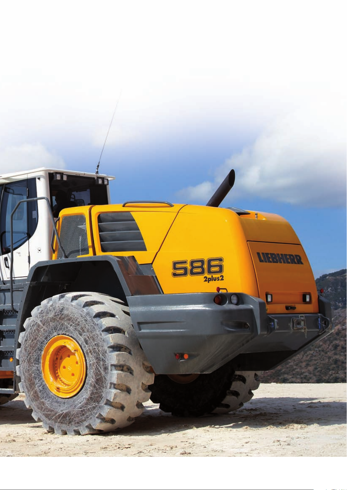
L 586
2plus2
Product Information
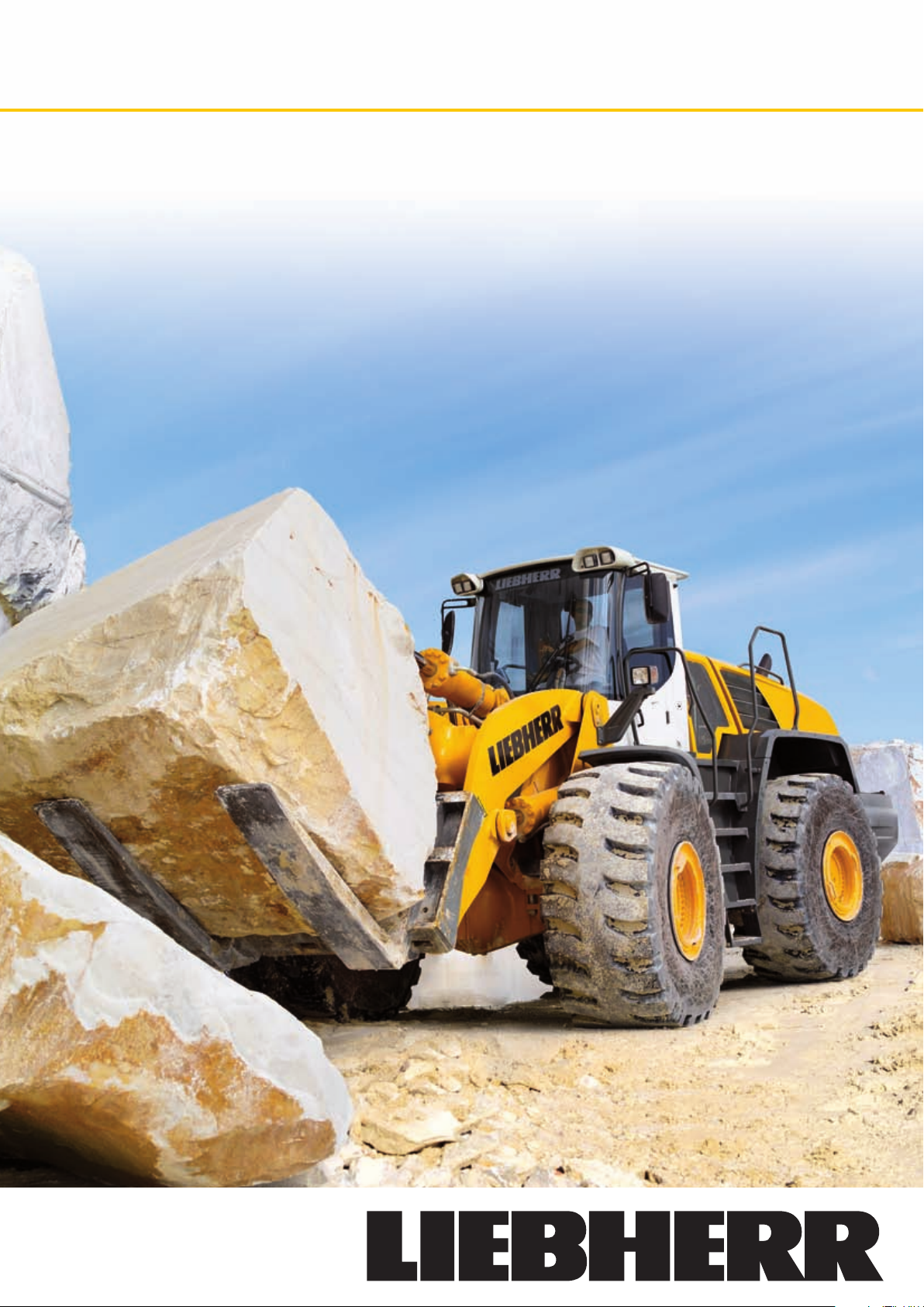
Block Handling
Page 2
Wheel loader for cost-effective
Block Handling
Marble has not only been used in art and sculpture for
centuries, but has also been very popular for architecture
and for both the interior and exterior design of buildings
throughout the ages.
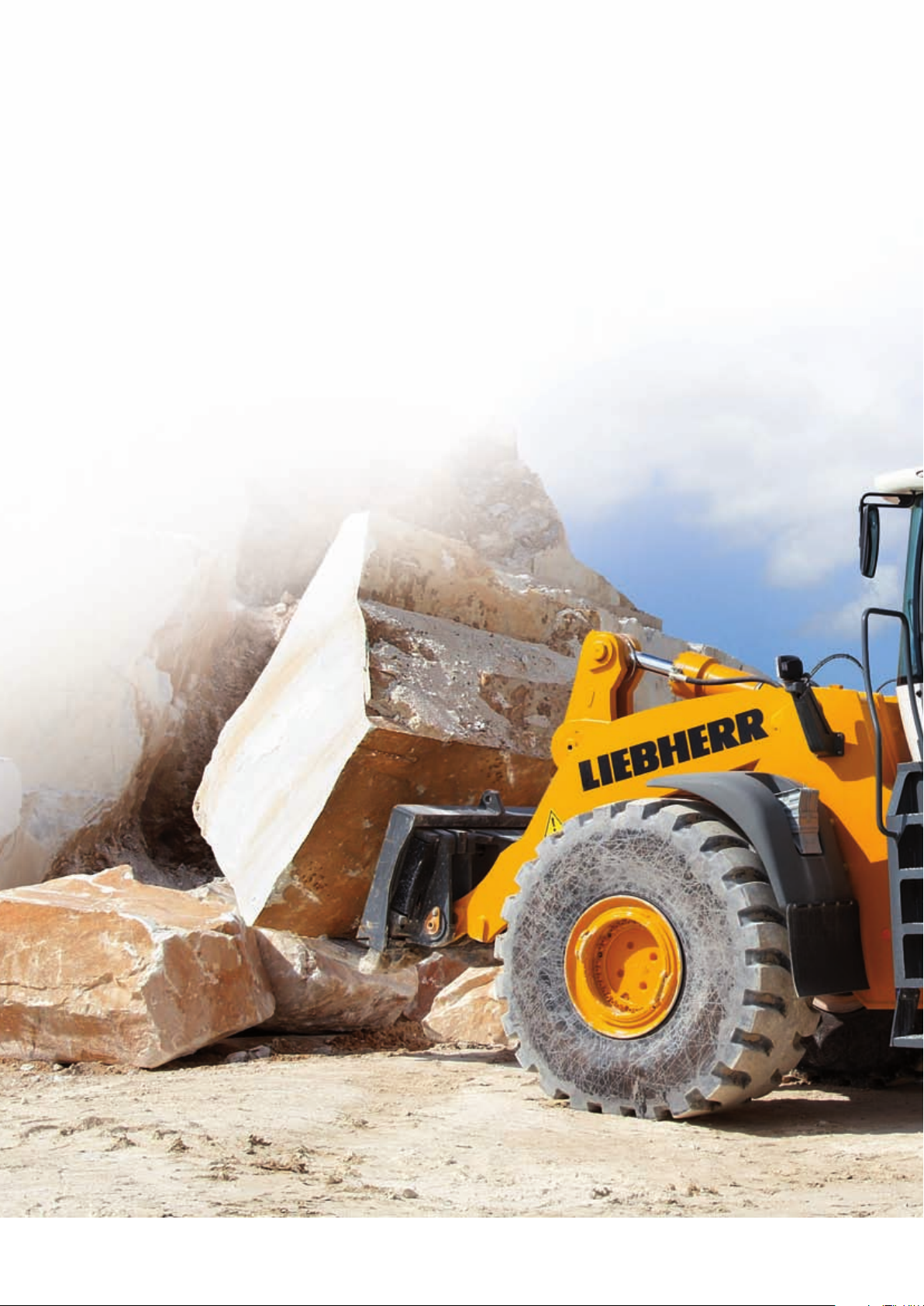
To ensure that the rock can be fi nished to the best possible effect it is extracted in the largest possible block sizes.
A wheel loader is then responsible for removing the solid,
valuable marble blocks. The block handling version of the
Liebherr L 586 2plus2 wheel loader has been specially
developed for this purpose.
The hydrostatic drive used in the block handling machines
from Liebherr provides the high level of economy and
safety to which Liebherr users have become accustomed.
It reduces fuel consumption by up to 25% and features
excellent weight distribution as a result of the unit installation position of the components. In addition the foot brake
suffers practically zero wear. When driving on gradients,
the hydrostatic braking effect massively enhances the
safety of the driver and the area around the machine.
Like all Liebherr wheel loaders, the block handling
machines are also operated using a single control lever.
The driver’s left hand can remain on the steering wheel at
all times, resulting in greater comfort and safety for him.
Liebherr has a range of optional equipment which has
been designed specially for block handling and using
which the wheel loader can be tailored perfectly to the
specifi c conditions in which it is used. The quick-change
device included in the block handling package provides a
high level of fl exibility.
Maximum performance, economy and reliability as well
as comfort in the equipment used in the machines make
Liebherr an ideal partner for block handling.
L 586 2plus2 Block Handling
2
Page 3
Economy
Compared to conventional transmission, the Liebherr
driveline achieves a reduction in fuel consumption for
wheel loaders of 25% or more! 5 litres less fuel per operating hour signifi cantly reduce operating costs and environmental pollution.
Reliability
All the materials used in Liebherr wheel loaders have
passed long-term tests to ensure that they match up
to Liebherr’s exacting standards even in the toughest
conditions. The mature concept and proven quality make
Liebherr wheel loaders to the benchmark for reliability.
Performance
The Liebherr driveline allows the Liebherr diesel engine to
be mounted lengthways in the rear, with the output shaft
facing backwards. Compared to conventionally driven
wheel loaders, the operating weight is much lower, the
tipping load is higher, and more material can be moved
each operating hour.
Comfort
The ultra-modern cab design with advanced ergonomics, continuously variable Liebherr driveline with 2plus2
gearbox for uninterrupted tractive force, standard
Liebherr ride control, optimum weight distribution and
easy service access thanks to unique engine installation
position lead to extraordinary overall comfort.
L 586 2plus2 Block Handling
3
Page 4

Technical Data
Engine
Liebherr diesel engine
Design
Cylinder inline
Combustion process
Rated output according
to ISO 9249
Max. torque
Displacement
Bore/Stroke
Air cleaner
Electrical system
Operating voltage
Capacity
Alternator
Starter motor
��������������������������
The exhaust emissions are below the limits in stage IIIA / Tier 3.
�������������
�������������������������
����������������
��������
�������������������
�������������������
�����������������
�������������������
������������
�����������������������
����������������������
�����������������
D936L A6
Liebherr diesel engine, water-cooled, exhaust turbo
charged with intercooler
6
Unit pump (PLD) microprocessor controlled
250 kW at 2,000 RPM
1,590 Nm at 1,500 RPM
10.52 litres
122/150 mm
Dry type with main and safety element, pre-cleaner,
service indicator on LCD display
24 V
170 Ah
28 V/80 A
24 V/6.6 kW
Travel Drive
Stepless hydrostatic travel drive
Design “2plus2”
Filtering system
Control
Travel speed range
Speed range 2 and A2
Speed range A3
The quoted speeds apply with the tyres that are
��������������
��������������
������������������������
����������������
Swash plate type variable flow pump and two varia-
ble axial piston motors in closed loop circuit with one
axle transfer case. Direction of travel in reversed by
changing the flow-direction of the variable-displace-
ment pump
Suction return line filter for closed circuit
By travel and inching pedal. The inching pedal makes
it possible to control the tractive and thrust forces
steplessly at full engine speed. The Liebherr joystick
is used to control forward and reverse travel
Speed range 1
����������������������������
�������������������
��������������������������
0 – 8.0 km/h
0 – 16.0 km/h
0 – 35.0 km/h
standard equipment on the loader
Axles
Four-wheel drive
���������������������������
Front axle
����������������������������
Rear axle
Height of obstacles which
can be driven over
Differentials
Reduction gear
Track width
�������������������������
���������������������
�������������������������
Fixed
Centre pivot, with 13° oscillating angle to each side
�����������
530 mm
With all four wheels remaining in contact with the
ground
Automatic limited-slip differentials
Planetary final drive in wheel hubs
2,400 mm with all types of tyres
Brakes
Wear-free service brake
Parking brake
The braking system meets the requirements of the EC guidelines 71/320.
�����������
����������������������
Self-locking of the hydrostatic travel drive (acting on
all four wheels) and additional pump-accumulator
brake system with wet multi-disc brakes (two sepa-
rate brake circuits)
Electro-hydraulically actuated spring-loaded brake
system on the transmission
Steering
������������������������������
Design
Angle of articulation
Emergency steering
���������������
���������������
“Load-sensing” swash plate type variable flow pump
with pressure cut-off and flow control. Central pivot
with two double-acting, damped steering cylinders
37° (to each side)
Electro-hydraulic emergency steering system
Attachment Hydraulics
������������������������������
Design
�����������������������������
Cooling
�����������������������������
Filtering
������������������������������
Control
���������������������������
Lift circuit
���������������������������
Tilt circuit
���������������������������
Max. flow
Max. pressure
����������������������
“Load-sensing” swash plate type variable flow pump
with output and flow control, and pressure cut-off in
the control block
Hydraulic oil cooling using thermostatically controlled
fan and oil cooler
Return line filter in the hydraulic reservoir
“Liebherr-Joystick” with hydraulic servo control
Lifting, neutral, lowering
and float positions controlled by Liebherr joystick
with detent
Tilt back, neutral, dump
automatic bucket positioning
410 l/min.
330 bar
Attachment
���������������������������
Geometry
����������������������������
Bearings
Cycle time at nominal load
Dumping
Lowering (empty)
Powerful Z-pattern linkage with tilt cylinder and cast
steel cross-tube
Sealed
�������
������������������������������������������������
Lifting
��������������������������������������������
�����������������������������������
Operator’s Cab
������������������������������
Design
Liebherr Operator’s seat
Cab heating and ventilation
On elastic bearing on rear section, soundproof
ROPS/FOPS cab. Operator’s door with optional
sliding window, 180° opening angle, fold-out window
on right site with opening angle, front windscreen
made of compound safety glass, green tinted as
standard, side windows made of single-pane safety
glass, grey tinted, continuously adjustable steering
column and joystick control as standard, heatable
rear window
ROPS roll over protection per DIN/ISO 3471/
EN 474-3
FOPS falling objects protection per DIN/ISO 3449/
EN 474-1
����������
6 way adjustable seat with lap belt, vibration
damping and suspension adjustable for the opera-
tor’s weight
�������
Operator’s cab with 4-level air control, cooling water
heating, defroster and air conditioning with electronic
valve control, as well as electronic fresh/recirculated
air control, filter system with pre-filter, fresh air filter
and recirculated air filter, easily replaced, air con-
ditioning as standard
Noise Emission
����������������������������
ISO 6396
2000/14/EC
�������������������������
LpA (inside cab) =
LWA (surround noise) =
69 dB(A)
107 dB(A)
Capacities
������������������������������������������������������������������������������������
Fuel tank
Engine oil (including filter change)
Pump distributor gears
Transmission “2plus2”
��������������������������������������������������������������������������������������
Coolant
������������������������������������������������������������������������������������
Front axle
�������������������������������������������������������������������������������������
Rear axle
Hydraulic tank
Hydraulic system, total
Air condition system R134a
��������������������������������������������������������������������
�������������������������������������������������������������������
������������������������������������������������������������������������������
��������������������������������������������������������������������
���������������������������������������������������������
������������������������������������������������������������
6.5 s
3.0 s
4.0 s
435 l
43 l
7.7 l
11.5 l
59 l
90 l
56 l
180 l
350 l
1,250 g
4 L 586 2plus2 Block Handling
Page 5

Optional Equipment
Rock Fork
Fork length mm 1,500
Fork mounting width mm 1,785
Height mm 1,320
Overall length * mm 1,611
Weight ** kg 1,820
Rock Bucket with Delta Cutting Edge and Teeth
Bucket capacity according to ISO 7546 m3 5.0
Specific material weight t/m
Bucket width mm 3,500
Overall length * mm 1,652
Weight ** kg 3,600
Rock Bucket with Bolt-On Cutting Edge
Bucket capacity according to ISO 7546 m3 5.0
Specific material weight t/m
Bucket width mm 3,500
Overall length * mm 1,393
Weight ** kg 3,230
3
1.8
3
1.8
Rock Bucket with Delta Cutting Edge
and Side Cutters
Bucket capacity according to ISO 7546 m3 5.8
Specific material weight t/m
Bucket width mm 3,645
Overall length * mm 1,856
Weight ** kg 3,800
3
1.6
Clearing Rake
Width mm 500
Overall length * mm 6,023
Weight ** kg 3,300
Rock Fork (1 Tine)
Fork length mm 1,100
Width mm 250
Height mm 1,460
Overall length * mm 1,200
Weight ** kg 1,580
* in addition to the length of the basic machine incl. quick change device (page 6)
** in addition to the operating weight of the basic machine incl. quick change device (page 6)
L 586 2plus2 Block Handling 5
Page 6

Dimensions
65°
45°
E
C
B
D
49º
F
H
I
J
G
K
L
General Dimensions
H Height above cab mm
I Height above exhaust mm
J Ground clearance mm
K Wheelbase mm
L Length – basic machine (incl. quick change device) mm
Width over tyres mm
Operating weight of the basic machine (incl. quick change device) *** kg
Tyre sizes
3,760
3,330
595
3,900
8,338
3,290
34,360
29.5R25 Goodyear RL5K
Rock Bucket
with Quick Change Device 5.0 m3 5.0 m3 BOCE 5.8 m
B Dump-over height mm
C Max. height of bucket bottom mm
D Dumping height at max. lift height and 45° discharge mm
E Max. operating height mm
F Reach at max. lift height and 45° discharge mm
G Digging depth mm
Tipping load, straight *** kg
Tipping load, articulated *** kg
Turning circle radius over outside bucket edge mm
* Dimension to the tip of the tooth
** Dimension to the front edge of the bucket cutting edge
*** The figures shown here are valid with tyres above, includes all lubricants, a full fuel tank, the ROPS/FOPS cab and the operator. Different tyres
and optional equipment will change the operating weight and tipping load.
BOCE = Bolt-on cutting edge
4,050 4,050 4,050
4,250 4,250 4,250
2,760* 3,120** 2,870*
6,590 6,365 6,650
1,840* 1,405** 1,740*
150 150 150
27,380 27,690 27,740
24,550 24,330 24,380
8,440* 8,300** 8,470*
3
6 L 586 2plus2 Block Handling
Page 7

Dimensions
F min.
900
E
C
D
A
R1
F max.
G
F
Stone Fork (2 Tines)
with Quick Change Device
A Lifting height at max. reach mm
C Max. lifting height mm
E Max. operating height mm
D Height of fork tines at max. lifting height and 45° tipping angle mm
F Reach at loading position mm
F max. Max. reach mm
F min. Reach at max. lifting height mm
G Digging depth mm
Turning circle over external edge of fork mm
R1 Roll back angle
Tipping Load, straight / Lifting Force
(t)
27
26
25
24
B
A
1,935
4,240
5,455
3,010
1,245
1,836
860
290
7,530
50°
Load Table
A Tipping load, straight
B Lifting force
H Working height
X 900 mm
Y 800 mm
23
22
Kipplast gerade / Hubkraft
21
Tipping Load, straight / Lifting Force
20
500 750 1000 1250 1500 1750 2000 2250 2500 2750 3000 3250 3500
The load capacity depends on the dimensions of the marble block and will be calculated when an inquiry is received.
L 586 2plus2 Block Handling 7
X
Y
H
(mm)
Arbeitshöhe (H)
Working Height (H)
Page 8

Equipment
Basic Machine
Exhaust pipe – stainless steel +
Automatic central lubrication system •
Battery master switch •
Fuel particle filter +
Electronic crowding force control •
Electronical theft protection with/without driver identification +
Automatic travel mode •
Headlights •
Ride control •
Fluff trap for radiator +
Pre-heat system for cold starting •
Creep speed/Cruise control •
Combined inching-braking system •
Multi-disc limited slip differentials in both axles •
LiDAT Standard (Liebherr Data Transfer System +
LiDAT Plus (extended Liebherr Data Transfer System) +
Liebherr-2plus2-travel gear •
Liebherr bio degredable hydraulic oil +
Air cleaner system with pre-filter •
Reversible fan drive +
Emergency steering system •
Back-up alarm +
Lockable doors, service flap and engine hood •
Rubber widening for rear (in steel) and front mudguards +
Toolbox with toolkit •
Weighing device (integrated) +
Towing hitch •
Two working area lights at rear •
Two tail lights •
20 km/h speed limiting +
Rev. counter •
Forward – reverse travel •
Travel speed ranges and gear selected •
High-beam headlights •
Fuel reserve •
Engine oil temperature •
Reverse travel •
Speedometer •
Clock •
Diesel engine pre-heat •
Forward travel •
Warning Lights for:
Battery charge •
Flow through emergency steering system •
Parking brake •
Hydraulic oil temperature •
Air cleaner blockage •
Engine oil pressure •
Engine overheat •
Audible Warnings for:
Overheat of hydraulic fluid •
Engine oil pressure •
Engine overheat •
Emergency steering system •
Operator’s Cab
Storage box •
Lockable storage compartment •
Ashtray •
Operator’s package •
Operator’s seat – adjustable in 6 ways •
Operator’s seat with active suspension, with seat climate control and seat heating +
Operator’s seat – air sprung with seat heating +
Fire extinguisher 2 kg +
Cup holder •
Height-adjustable steering column +
Horn •
Joystick steering +
Floor mat •
Clothes hook •
Air conditioning system •
Storage box with cooling function +
LED operating spotlight, front/rear +
Liebherr joystick control – adjustable •
Radio set +
Provision for radio including loudspeaker +
Rear view monitoring with camera +
Interior rear-view mirror •
Amber beacon +
Soundproof ROPS/FOPS cab with tinted safety glass front windscreen,
heatable rear window
Wash/wipe system for windscreen and rear window •
Sliding window +
Protective ventilation system +
Windscreen guard +
Sun visor •
Dust filter system +
Plug 12 V •
First aid kit +
Adjustable steering column •
Four working area lights at front •
Hot water heater with defroster and recirculated-air system •
Wide angle mirror +
Xenon working lights front +
Two or four working area lights rear +
Function Keys for:
Working lights rear •
Working lights front •
Electronic tractive force adaptation •
Speed range selection •
Headlights •
Ride control •
Parking brake •
Blower •
Heater •
Hoist kick-out +
Air conditioning •
Creep speed •
Mode switch •
Amber beacon •
Automatic bucket positioner •
Wash/wipe system for rear window •
Float position •
Road travel •
Hazard warning flashers •
Additional hydraulics •
•
Equipment
Automatic hoist kick out – adjustable +
Automatic bucket positioner – adjustable •
Hydraulic quick-change device •
Hydraulic servo control of working hydraulics •
Comfort control +
Loading buckets with and without teeth, or bolt-on cutting edge
Country-specific versions +
Float position •
Z-bar linkage •
3rd hydraulic control circuit +
3rd and 4th hydraulic control circuits +
+
586 Block Handling 03.10
Instruments for:
Timer for hours of operation •
Flashing turn indicators •
Diagnosis system •
• = Standard, + = Option
Liebherr-Werk Bischofshofen GmbH
Postfach 49, A-5500 Bischofshofen
S +43 50809 1-0, Fax +43 50809 11385
www.liebherr.com, E-Mail: info.lbh@liebherr.com
Printed in Germany by Typodruck RG-BK-RP LBH/PM 11000428-1-03.10_enGB All illustrations and data may differ from standard equipment. Subject to change without notice.
 Loading...