


 Loading...
Liebert®
GXT5™ UPS
Installer/User Guide
200 V to 240 V, 750 VA to 3,000 VA

The information contained in this document is subject to change without notice and may not be suitable for all applications. While every precaution has been taken to ensure the accuracy and completeness of this document, Vertiv assumes no responsibility and disclaims all liability for damages resulting from use of this information or for any errors or omissions. Refer to other local practices or building codes as applicable for the correct methods, tools, and materials to be used in performing procedures not specifically described in this document.
The products covered by this instruction manual are manufactured and/or sold by Vertiv. This document is the property of Vertiv and contains confidential and proprietary information owned by Vertiv. Any copying, use or disclosure of it without the written permission of Vertiv is strictly prohibited.
Names of companies and products are trademarks or registered trademarks of the respective companies. Any questions regarding usage of trademark names should be directed to the original manufacturer.
Technical Support Site
If you encounter any installation or operational issues with your product, check the pertinent section of this manual to see if the issue can be resolved by following outlined procedures. Visit https://www.Vertiv.com/en-us/support/ for additional assistance.
Vertiv |Liebert® GXT5™Installer/UserGuide

TABLE OF CONTENTS
Important Safety Information |
1 |
1 GXT5 Description |
3 |
1.1 UPS Features and Available Models |
3 |
1.2 Front Panels |
4 |
1.3 Rear Panels |
5 |
1.4 Battery Cabinet |
11 |
1.5 Major Internal Components and Operating Principle |
11 |
1.6 UPS States and Operating Modes |
13 |
1.6.1 Normal Mode |
13 |
1.6.2 Bypass Mode |
13 |
1.6.3 Battery Mode |
13 |
1.6.4 Frequency Converter Mode |
13 |
1.6.5 ECO Mode |
14 |
2 Installation |
15 |
2.1 Unpacking and Inspection |
15 |
2.2 Pre-installation Preparation |
15 |
2.2.1 Installation Clearances |
15 |
2.3 Installing the UPS |
15 |
2.3.1 Tower Installation |
16 |
2.3.2 Rack Installation |
16 |
2.4 Installing External Battery Cabinets |
16 |
2.5 Connecting AC Input Power |
19 |
2.6 Connecting Loads |
19 |
2.7 Communication Connections |
20 |
2.7.1 Connecting IntelliSlot Communication |
20 |
2.7.2 Connecting to the Dry-contact Port |
21 |
2.7.3 Connecting a Remote Emergency Power-off (REPO) Switch |
22 |
2.7.4 Connecting a USB Cable |
23 |
2.7.5 Connecting Sensors to the Control Port |
24 |
3 Operating the UPS |
25 |
3.1 Silencing the Audible Alarm |
25 |
3.2 Starting-up the UPS |
25 |
3.3 Transferring to Battery Mode |
25 |
3.4 Transferring from Normal to Bypass Mode |
26 |
3.5 Transferring from Bypass to Normal Mode |
26 |
3.6 Shutting-down the UPS Completely |
26 |
3.7 Remote Emergency Power-off (REPO) |
26 |
3.8 Auto and Manually Restarting |
26 |
4 Operation and Display Panel |
29 |
4.1 LED Indicators |
31 |
Vertiv | Liebert® GXT5™ Installer/User Guide | |
iii |

4.2 |
LCD Menu and Screens |
31 |
|
4.2.1 Start-up and Flow Screens |
31 |
|
4.2.2 Main Menu |
32 |
4.3 |
Editing Display and Operation Settings |
47 |
|
4.3.1 Settings Prompts |
47 |
|
4.3.2 Changing the Password |
48 |
|
4.3.3 Selecting the Display Language |
49 |
|
4.3.4 Setting the Date and Time |
49 |
5 Maintenance |
51 |
|
5.1 Replacing Batteries |
51 |
|
5.2 Charging Batteries |
53 |
|
5.3 Checking UPS Operation |
54 |
|
5.4 |
Cleaning the UPS |
54 |
6 Troubleshooting |
55 |
|
6.1 Symptoms that Require Troubleshooting |
55 |
|
6.2 |
Audible Alarm (Buzzer) |
55 |
|
6.2.1 Faults |
55 |
6.3 |
Troubleshooting UPS Issues |
56 |
7 Specifications |
57 |
|
7.1 Battery Run Times |
63 |
|
Appendices |
69 |
|
Appendix A: Technical Support |
69 |
|
Vertiv | Liebert® GXT5™ Installer/User Guide | |
iv |

IMPORTANT SAFETY INFORMATION
IMPORTANT! This manualcontains important safetyinstructions that must be followed during the installation and maintenance of the UPS and batteries. Read this manualthoroughlyand the safetyand regulatoryinformation, available at https://www.vertivco.com/ComplianceRegulatoryInfo, before attempting to install, connect to supply, oroperate this UPS.
1

This page intentionally left blank
2 |
Vertiv |Liebert® GXT5™Installer/UserGuide |
|

1 GXT5 DESCRIPTION
The Liebert® GXT5 is a compact, online uninterruptible power system (UPS) that continuously conditions and regulates its output voltage. The Liebert® GXT5 supplies microcomputers and other sensitive equipment with clean sine-wave input power.
Upon generation, AC power is clean and stable. However, during transmission and distribution it is subject to voltage sags, spikes, and complete failure that may interrupt computer operations, cause data loss, and damage equipment.
The Liebert® GXT5 protects equipment from these disturbances. The Liebert® GXT5 continuously charges its batteries from the mains, enabling it to supply power to connected loads, even when the mains fail.
1.1 UPS Features and Available Models
The GXT5 includes the following features. Table 1.1 below, lists the available models and power ratings.
•Optional tower or rack installation to meet varying installation requirements.
•Adapts to areas with unstable power-mains supply via high-frequency double-conversion topology structure, with high input-power factor, wide input-voltage range, and output immune to grid interference.
•Full digital-control platform and hardware-design platform adapts to unstable mains supply and load impact
•Programmable terminals with cascade protection protect key devices when load is heavy.
•Operation and display panel with model-specific color LCD offers simple configuration and control of the UPS.
•ECO power-supply mode and smart-sleep mode help you save the maximum amount of energy.
Table 1.1 UPS Models and PowerRatings
MODEL NUMBER |
NOMINAL POWER RATING |
|
GXT5-750IRT2UXL |
750 VA/750 W |
|
GXT5-750IRT2UXLE |
||
|
||
GXT5-1000IRT2UXL |
|
|
1000 VA/1000 W |
||
GXT5-1000IRT2UXLE |
||
|
||
GXT5-1500IRT2UXL |
|
|
1500 VA/1500 W |
||
GXT5-1500IRT2UXLE |
||
|
||
GXT5-2000IRT2UXL |
|
|
2000 VA/2000 W |
||
GXT5-2000IRT2UXLE |
||
|
||
GXT5-3000IRT2UXL |
|
|
3000 VA/3000 W |
||
GXT5-3000IRT2UXLE |
||
|
||
|
|
|
GXT5-3KL620RT2UXL |
3000 VA/2700 W |
|
|
|
|
GXT5-3KL630RT2UXL |
3000 VA/3000 W |
|
|
|
1 GXT5 Description |
3 |
|
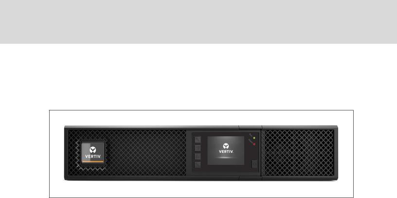
1.2 Front Panels
The various GXT5 models have the same general appearance, with the main difference being the receptacle types on the rear panel.
Figure 1.1 Front View
4 |
Vertiv |Liebert® GXT5™Installer/UserGuide |
|

1.3 Rear Panels
The following figures detail the rear-panel features for each GXT5 model.
Figure 1.2 GXT5-750/1000IRT2UXL (XLE) RearPanel
ITEM |
DESCRIPTION |
1 |
Liebert®IntelliSlot™port |
2 |
VentilationHole |
3 |
External-battery-cabinet connector |
4 |
Input circuit-breaker reset button, 10-A |
5 |
Non-programmable C13 output receptacles |
6 |
Programmable C13 output receptacles |
7 |
C14input-power plugandcable |
8 |
Terminal-block/Dry-contact communicationconnectors |
9 |
RS-232 port |
10 |
RS-485 port |
11 |
USB port |
1 GXT5 Description |
5 |
|

Figure 1.3 GXT5-1500IRT2UXL (XLE) RearPanel
ITEM |
DESCRIPTION |
1 |
Liebert®IntelliSlot™port |
2 |
VentilationHole |
3 |
External-battery-cabinet connector |
4 |
Input circuit-breaker reset button, 10-A |
5 |
Non-programmable C13 output receptacles |
6 |
Programmable C13 output receptacles |
7 |
C14input-power plugandcable |
8 |
Terminal-block/Dry-contact communicationconnectors |
9 |
RS-232 port |
10 |
RS-485 port |
11 |
USB port |
6 |
Vertiv |Liebert® GXT5™Installer/UserGuide |
|
Figure 1.4 GXT5-2000IRT2UXL (XLE) RearPanel
ITEM |
DESCRIPTION |
1 |
Liebert®IntelliSlot™port |
2 |
VentilationHole |
3 |
External-battery-cabinet connector |
4 |
Non-programmable C13 output receptacles |
5 |
Programmable C13 output receptacles |
6 |
C20 input-power plugandcable |
7 |
Input circuit-breaker reset button, 16-A |
8 |
Terminal-block/Dry-contact communicationconnectors |
9 |
RS-232 port |
10 |
RS-485 port |
11 |
USB port |
1 GXT5 Description |
7 |
|
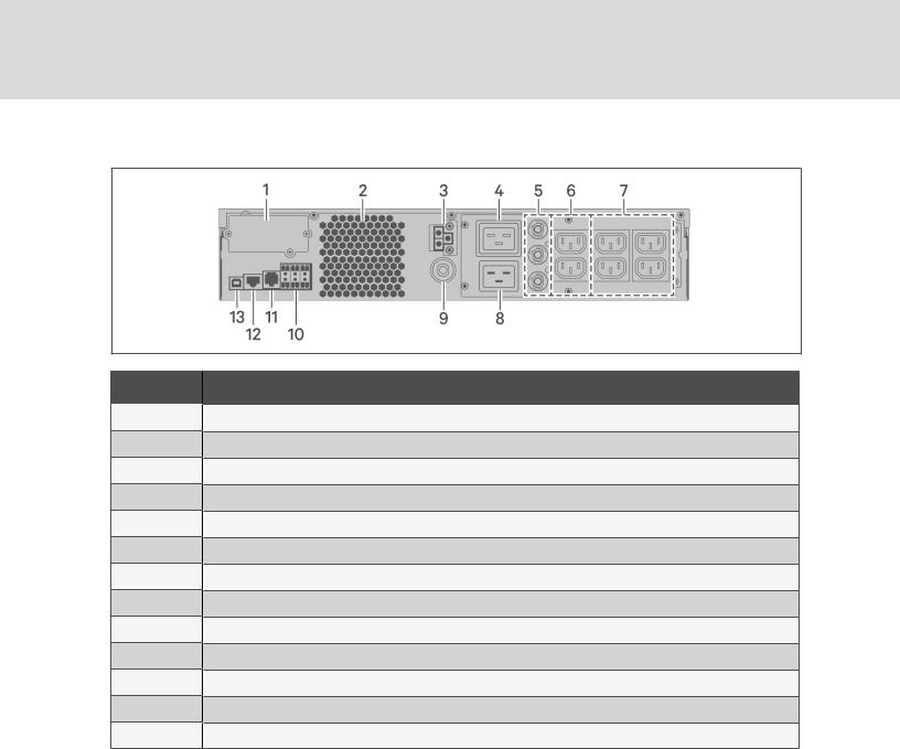
Figure 1.5 GXT5-3000IRT2UXL (XLE) RearPanel
ITEM |
DESCRIPTION |
1 |
Liebert®IntelliSlot™port |
2 |
VentilationHole |
3 |
External-battery-cabinet connector |
4 |
Non-programmable C19output receptacle |
5 |
Output circuit-breaker reset buttons, 10-A |
6 |
Non-programmable C13 output receptacles |
7 |
Programmable C13 output receptacles |
8 |
C20 Input-power plugandcable |
9 |
Input circuit-breaker reset button, 20-A |
10 |
Terminal-block/Dry-contact communicationconnectors |
11 |
RS-232 port |
12 |
RS-485 port |
13 |
USB port |
8 |
Vertiv |Liebert® GXT5™Installer/UserGuide |
|

Figure 1.6 GXT5-3KL620RT2UXL RearPanel
ITEM |
DESCRIPTION |
1 |
Liebert®IntelliSlot™port |
2 |
VentilationHole |
3 |
External-battery-cabinet connector |
4 |
Input power cable, L6-20P |
5 |
Output circuit-breaker reset buttons, 20-A |
6 |
Output cable, L6-20R |
7 |
Output circuit-breaker reset buttons, 15-A |
8 |
Output cables, L6-15R |
9 |
Input circuit-breaker reset button |
10 |
Terminal-block/Dry-contact communicationports |
11 |
RS-232 port |
12 |
RS-485 port |
13 |
USB port |
1 GXT5 Description |
9 |
|

Figure 1.7 GXT5-3KL630RT2UXL RearPanel
ITEM |
DESCRIPTION |
1 |
Liebert®IntelliSlot™port |
2 |
VentilationHole |
3 |
External-battery-cabinet connector |
4 |
Input power cable, L6-30P |
5 |
Output circuit-breaker reset buttons, 20-A |
6 |
Output cable, L6-30R |
7 |
Output circuit breakers, 15-A |
8 |
Output cables, L6-15R |
9 |
Input circuit-breaker reset button |
10 |
Terminal-block/Dry-contact communicationports |
11 |
RS-232 port |
12 |
RS-485 port |
13 |
USB port |
10 |
Vertiv |Liebert® GXT5™Installer/UserGuide |
|
1.4 Battery Cabinet
Optional battery cabinets are available for the UPS, and include a single battery-connector cable. Up to 10 battery cabinets may be connected in parallel to the UPS, and up to 6 can be detected using EBCdetection. See Table 7.4 on page 63, for the cabinet specifications. For approximate battery run times with additional EBCs, see Battery Run Times on page 63. See Installing External Battery Cabinets on page 16, to connect the cabinets.
Figure 1.8 BatteryCabinet
ITEM. |
DESCRIPTION |
1 |
Batteryconnectors |
|
|
2 |
Isolationbreaker |
|
|
1.5 Major Internal Components and Operating Principle
Figure 1.9 on the next page, shows the UPS operating principle. Table 1.2 on the next page, describes the function of the major components in the UPS.
NOTE: Figure 1.9 on the next page, is one example of basic operation.
1 GXT5 Description |
11 |
|

Figure 1.9 Basic Operating Principle Diagram
Table 1.2 MajorComponents
ITEM COMPONENT OPERATION/FUNCTION
1
2
3
4
5
6
7
8
9
Transient |
|
Voltage Surge |
Provide surge protection. Filter electromagnetic interference (EMI)andradio frequencyinterference |
Suppression |
(RFI). Minimize surgesor interference present inthe utilitypower andprotect devicesconnectedonthe |
(TVSS)and |
same branchasthe UPS. |
EMI/RFI Filters |
|
|
|
Rectifier/Power |
Innormaloperation, convertsutilityACpower to regulatedDCpower for use bythe inverter while |
Factor |
ensuringthat the wave shape ofthe input current usedbythe UPSisnear ideal. Extractingthissine-wave |
Correction |
input current ensuresefficient use ofutilitypower andreducesreflectedharmonic distortionmaking |
(PFC)Circuit |
cleaner power available to devicesthat are not protectedbythe UPS. |
|
|
|
Valve-regulated, non-spillable, lead-acidbatteries. |
Batteries |
NOTE: To maintain battery design life, operate the UPS in an ambient temperature of 59°F to 77°F |
|
|
|
(15°C to 25°C). |
DC-to-DC
Converter
Inverter
Dynamic
InternalBypass
Raisesthe DCvoltage from the batteryto the optimum operatingvoltage for the inverter. Thisallowsthe inverter to operate continuouslyat itsoptimum efficiencyandvoltage, thusincreasingreliability.
Innormaloperation, invertsthe DCoutput ofthe PFCcircuit into precise, regulatedsine-wave ACpower. Whenutilitypower fails, the inverter receivesDCpower from the DC-to-DCconverter. Ineither operatingmode, the UPSinverter remainson-line, generatingclean, precise, regulatedAC-output power.
Inthe unlikelyevent ofUPSfailure suchasoverloador over-temperature, automaticallytransfersthe connectedloadto bypass.
To manuallytransfer the connectedloadfrom inverter to bypass, see Transferringfrom Normalto BypassMode onpage 26.
EMI/RFI Filters |
Filter electromagnetic interference (EMI)andradio frequencyinterference (RFI). Minimize interference |
|
present inthe utilitypower andprotect devicesconnectedonthe same branchasthe UPS. |
||
|
||
|
|
|
Outlet group |
Programmable output receptacles. |
|
|
|
|
Outlet group |
Generaloutput receptacles. |
|
|
|
12 |
Vertiv |Liebert® GXT5™Installer/UserGuide |
|

1.6 UPS States and Operating Modes
NOTE: See LEDIndicators on page 31, fordescription of the run-indicatorand alarm-indicatorLEDs mentioned in this section.
1.6.1 Normal Mode
When utility power is normal, Normal mode employs the rectifier and inverter to provide voltageand frequency-stabilized power to the load. The charger charges the battery in normal mode. On the frontpanel display, the run-indicator (green) is On, the alarm indicator is OFF, and the buzzer is silent.
1.6.2 Bypass Mode
Bypass mode supplies power to the load from the bypass source (utility power) if an overload or fault occurs during normal operation. On the front-panel display, the run indicator (green) is On, the alarm indicator (yellow) is On, and the buzzer beeps once each seconds. The LCD "Current" screen displays "On Bypass."
NOTE: If utilitypowerfails orif the utilityvoltage goes outside of the permissible range during bypassmode operation, the UPS shuts down and no output is supplied to the load.
1.6.3 Battery Mode
Battery mode supplies battery power to the load if utility power fails or if the utility voltage goes outside of the permissible range. On the front-panel display, the run indicator (green) is On, the alarm indicator (yellow) is On, and the buzzer beeps once each second. The LCD "Current" screen displays "On Battery."
NOTE: The batteries are fully-charged before shipment. However, transportation and storage inevitablycause some loss of capacity. To ensure adequate back-up time, charge the batteries foratleast 8 hours before first start-up.
NOTE: If utilitypowerfails and the batteries are charged, you maycold-start the UPS in batterymode and use batterypowerto extend system availabilityfora time.
NOTE: Powering-off the UPS when it is in batterymode results in loss of output powerto the connected load.
1.6.4 Frequency Converter Mode
All models of the GXT5 are capable of frequency conversion. Frequency Conversion Mode can be selected using the configuration program. Allowable frequency operating modes include:
•Auto Sensing - 50 Hzor 60Hz – Bypass Enabled
•Auto Sensing - 50 Hzor 60Hz – Bypass Disabled
•Frequency Converter - 50 Hz – Bypass Disabled
•Frequency Converter - 60Hz – Bypass Disabled
NOTE: The default forallmodels of the Liebert®GXT5is “Auto Sensing - 50Hz or60Hz – Bypass Enabled.”
1 GXT5 Description |
13 |
|

1.6.5 ECO Mode
The energy-saving ECO mode reduces power consumption by powering the load via bypass if the bypass voltage is normal or by powering the load via the inverter when the bypass voltage is abnormal. You can use ECO mode to power equipment that is not sensitive to power-grid quality to via bypass and reduce power consumption.
NOTE: During Eco mode, if a bypass-failure orabnormal-bypass-voltage notification appears when the output is not overloaded, the UPS willtransferto NormalMode. However, if a notification showing bypass failure orabnormalbypass voltage appears when the output is overloaded, the UPS willshut down the bypass.
14 |
Vertiv |Liebert® GXT5™Installer/UserGuide |
|

2 INSTALLATION
Do not start the UPS until after the installation is finished.
 WARNING! Risk of electricalshock. Can cause equipment damage, injuryand death. Before beginning installation, verifythat allexternalovercurrent protection devices are open (Off), and that theyare locked-out and tagged appropriatelyto prevent activation during the installation, verifywith a voltmeterthat poweris Off and wearappropriate, OSHA-approved personal protective equipment (PPE) perNFPA 70E. Failure to complycan cause serious injuryordeath. Before proceeding with installation, read allinstructions. Follow alllocalcodes.
2.1 Unpacking and Inspection
Unpack the UPS and conduct the following checks:
•Inspect the UPS for shipping damage. If any shipping damage is found, report it to the carrier and your local Vertiv representative immediately.
•Check the accessories included against the packing list. If there is any discrepancy, contact your local Vertiv representative immediately.
 CAUTION: The UPS is heavy(see Specifications on page 57, forthe weight). Take proper precautions when lifting ormoving the unit.
2.2Pre-installation Preparation
•Install the UPS indoors in a controlled environment, where it cannot be accidentally turned Off. The installation environment should meet the specifications listed in Specifications on page 57.
•Place the UPS in an area of unrestricted air-flow around the unit, away from water, flammable liquids, gases, corrosives, and conductive contaminants. Avoid direct sunlight
NOTE: Operating the UPS in temperatures above 77°F (25°C) reduces batterylife.
2.2.1 Installation Clearances
Maintain at least 4 in. (100 mm) clearance in the front and rear of the UPS. Do not obstruct the air inlets on the front panel and rear panel of the UPS. Blocking the air inlets reduces ventilation and heat dissipation, shortening the service life of the unit.
2.3 Installing the UPS
The UPS may be installed as a tower or in a rack, depending on available space and use considerations. Determine the type of installation and follow the appropriate instructions. See Tower Installation on the next page or Rack Installation on the next page.
NOTE: When installing the UPS ormaking input and output connections, complywith allrelevant safetycodes and standards
2 Installation |
15 |
|
2.3.1 Tower Installation
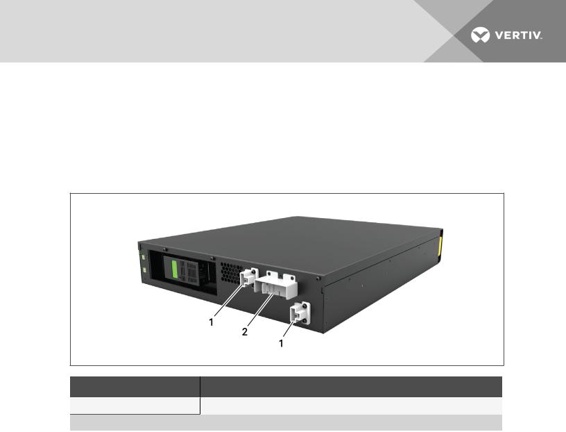
ToinstalltheUPSasatower:
1.Take the support bases out of the accessories box.
Figure 2.1 Support bases
NO. DESCRIPTION
1 |
Support bases |
Spacerswithconnectors
2NOTE: Three spacers are shown here. However, the number of spacers varies depending on your UPS model and the number of battery cabinets in your system.
2.If optional, Liebert® external battery cabinets will be connected, take out the spacers shipped with the battery cabinet.
3. Connect the spacers and the support bases as shown in Figure 2.1 above. Each GXT5 requires 2 support bases, one in the front and one in the rear.
4.Place the GXT5 and any battery cabinets on the 2 support bases.
2.3.2Rack Installation
When installed in a rack enclosure, the GXT5 UPS and external battery cabinets (EBC) must be supported by a shelf or rack-mount rails. Because different rack-mount options install differently, refer to the installation instructions provided with the rack-mount kit.
 CAUTION: The GXT5is heavy. The UPS must be installed as nearthe bottom of a rack as possible. If placed too high, it can make the rack top-heavyand prone to tipping over. Forunit weights, see Specifications on page 57.
2.4 Installing External Battery Cabinets
Optional, external battery cabinets (EBC) may be connected in parallel to the UPS to provide additional battery run time. For approximate battery run times with additional EBCs, see Battery Run Times on page 63.
External battery cabinets are placed on one side of the UPS in a tower configuration or stacked beneath the UPS in a rack configuration. Up to 10 EBCs may be connected to the UPS, and up to 6 may be detected using EBC-detection.
16 |
Vertiv |Liebert® GXT5™Installer/UserGuide |
|
 WARNING! Risk of electric shock. Can cause injuryordeath. Disconnect alllocaland remote electric powersupplies before working with the UPS. Ensure that the unit is shut down and powerhas been disconnected before beginning anymaintenance.
 CAUTION: The externalbatterycabinet(s) are heavy, see Table 7.4 on page 63. Take proper precautions when lifting them.
ToinstalltheEBC(s):
1.Inspect the EBC for freight damage. Report damage to the carrier and your local dealer or Vertiv representative.
2.For tower installation:
•An additional set of support-base extensions ships with each EBC.
•See the steps in Tower Installation on the previous page, to connect the support extenders and install the bases.
–or –
For rack installation:
•Rack-mount hardware ships with the EBC.
•Refer to the instructions included with the rack-mount kit to install.
NOTE: Optionalslide rails and securing hardware are sold separately. Please contact yourVertiv representative foroptions and VertivTechnicalSupport forassistance.
3.Verify that the EBC breaker is in the "Off" position.
4.Connect the supplied EBC cable(s) to the rear of the cabinet, then to the rear of the UPS, see Figure 2.2 on the next page.
5.Turn the EBC breaker to the "On" position.
6.Verify the circuit breaker on the EBC is in the "On" position. The additional back-up run time is enabled.
NOTE: When removing an EBC, turn off the circuit breakeron the rearof the cabinet before disconnecting the cable.
NOTE: If shipping orstoring the UPS foran extended time, disconnect the EBC(s) minimize stand-by current drain on the batteries and help maintain design life.
2 Installation |
17 |
|

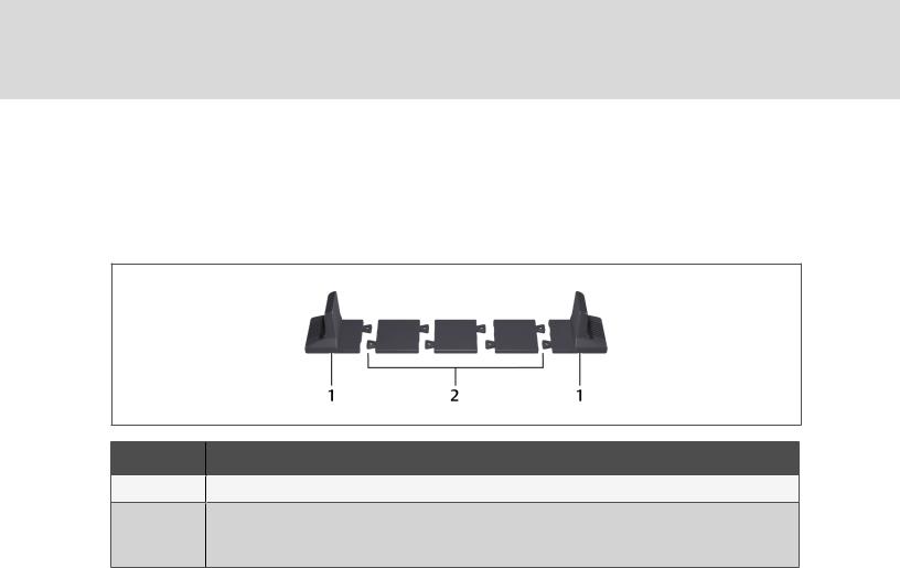
Figure 2.2 EBCs connected to the UPS
ITEM DESCRIPTION
1 |
EBC-detectiondry-contact port (See Table 2.2 onpage 22, for details.) |
2 EBCconnector
3 EBC-detectionport
4 Externalbatterycabinet
5Externalbatterycabinet
18 |
Vertiv |Liebert® GXT5™Installer/UserGuide |
|

2.5 Connecting AC Input Power
Ensure that all the loads are turned Off. Prepare an input power supply that is properly protected by a circuit breaker in accordance with national and local electrical codes. The wall receptacle must be grounded. We recommend installing an upstream circuit breaker of the same series as the input circuit breaker of the GXT5.
Table 2.1 below, lists the specifications of the input circuit breaker on the rear panel by UPS model
Table 2.1 Input circuit breaker specifications
MODEL |
RATED CIRCUITBREAKER |
|
GXT5-750IRT2UXL |
10 A |
|
GXT5-750IRT2UXLE |
||
|
||
GXT5-1000IRT2UXL |
|
|
10 A |
||
GXT5-1000IRT2UXLE |
||
|
||
GXT5-1500IRT2UXL |
|
|
10 A |
||
GXT5-1500IRT2UXLE |
||
|
||
GXT5-2000IRT2UXL |
|
|
16A |
||
GXT5-2000IRT2UXLE |
||
|
||
GXT5-3000IRT2UXL |
|
|
20 A |
||
GXT5-3000IRT2UXLE |
||
|
||
|
|
|
GXT5-3KL620RT2UXL |
20 A |
|
|
|
|
GXT5-3KL630RT2UXL |
20 A |
|
|
|
To connect AC-input power, plug the input plug of the UPS into the input-power connection.
NOTE: If the input plug willserve as the disconnecting device, the wallsocket/outlet must be nearthe UPS and must be easilyaccessible, perthe NationalElectric Code/NFPA 70requirements.
2.6 Connecting Loads
750-Va to 2000-VA models have three groups of outlets:
•One group is not controlled (always On).
•Two groups are controlled with programmed responses or an SNMP network.
3000-A models have four groups of outlets:
•Two groups are not controlled (always On).
•Two groups are controlled with programmed responses or an SNMP network.
NOTE: When connecting load, verifythat the equipment is plugged into the appropriate outlets if any of the outlets willbe controlled.
NOTE: Do not overload anyoutput receptacle. Output cable length should not exceed 10 m (32.8 ft).
2 Installation |
19 |
|
Loading...