


 Loading...
AC POWER SYSTEMS
SERIES 610™ UPS
OPERATION & MAINTENANCE MANUAL
100-1000kVA, 60Hz Three Phase Single-Module

BATTERY CABINET PRECAUTIONS
The following warning applies to all battery cabinets supplied with UPS systems. Additional warnings and cautions applicable to battery cabinets may be found in Important Safety Instructions and 4.4 - Battery Maintenance.
! WARNING
Internal battery strapping must be verified by manufacturer prior to moving a battery cabinet (after initial installation).
•Battery cabinets contain non-spillable batteries.
•Keep units upright.
•Do not stack.
•Do not tilt.
Failure to heed this warning could result in smoke, fire or electric hazard.
Call 1-800-LIEBERT prior to moving battery cabinets (after initial installation).
CONTACTING LIEBERT FOR SUPPORT
To contact Liebert Global Services for information or repair service in the United States, call 1-800-LIEBERT (1-800-543-2378). Liebert Global Services offers a complete range of start-up services, repair services, preventive maintenance plans and service contracts.
For repair or maintenance service outside the 48 contiguous United States, contact Liebert Global Services, if available in your area. For areas not covered by Liebert Global Services, the authorized distributor is responsible for providing qualified, factory-authorized service.
For LGS to assist you promptly, please have the following information available:
Part numbers: _________________________________________________________________
Serial numbers:________________________________________________________________
kVA Rating: ___________________________________________________________________
Date purchased: _______________________________________________________________
Date installed:_________________________________________________________________
Location: ______________________________________________________________________
Input voltage/frequency:________________________________________________________
Output voltage/frequency: ______________________________________________________
Battery reserve time:___________________________________________________________

TABLE OF CONTENTS
BATTERY CABINET PRECAUTIONS . . . . . . . . . . . . . . . . . . . . . . . . . . . . . . . . . INSIDE FRONT COVER
CONTACTING LIEBERT FOR SUPPORT . . . . . . . . . . . . . . . . . . . . . . . . . . . . . . INSIDE FRONT COVER
IMPORTANT SAFETY INSTRUCTIONS . . . . . . . . . . . . . . . . . . . . . . . . . . . . . . . . . . . . . . . . . . . . . . . .1
1.0 INTRODUCTION . . . . . . . . . . . . . . . . . . . . . . . . . . . . . . . . . . . . . . . . . . . . . . . . . . . . . . . . . .2
1.1 System Description. . . . . . . . . . . . . . . . . . . . . . . . . . . . . . . . . . . . . . . . . . . . . . . . . . . . . . . . . . . 2
1.2 Reliability . . . . . . . . . . . . . . . . . . . . . . . . . . . . . . . . . . . . . . . . . . . . . . . . . . . . . . . . . . . . . . . . . . 3
1.3 Safety Precautions . . . . . . . . . . . . . . . . . . . . . . . . . . . . . . . . . . . . . . . . . . . . . . . . . . . . . . . . . . . 4
1.4 Modes of Operation. . . . . . . . . . . . . . . . . . . . . . . . . . . . . . . . . . . . . . . . . . . . . . . . . . . . . . . . . . . 5
1.4.1 Normal—Load on UPS . . . . . . . . . . . . . . . . . . . . . . . . . . . . . . . . . . . . . . . . . . . . . . . . . . . . . . . . . 5
1.4.2 Input Power Failure . . . . . . . . . . . . . . . . . . . . . . . . . . . . . . . . . . . . . . . . . . . . . . . . . . . . . . . . . . . 5
1.4.3 Recharge . . . . . . . . . . . . . . . . . . . . . . . . . . . . . . . . . . . . . . . . . . . . . . . . . . . . . . . . . . . . . . . . . . . . 5
1.4.4 Overload . . . . . . . . . . . . . . . . . . . . . . . . . . . . . . . . . . . . . . . . . . . . . . . . . . . . . . . . . . . . . . . . . . . . 5
1.4.5 Bypass—Internal . . . . . . . . . . . . . . . . . . . . . . . . . . . . . . . . . . . . . . . . . . . . . . . . . . . . . . . . . . . . . 5
1.4.6 Maintenance Bypass. . . . . . . . . . . . . . . . . . . . . . . . . . . . . . . . . . . . . . . . . . . . . . . . . . . . . . . . . . . 5
1.4.7 Off-Battery . . . . . . . . . . . . . . . . . . . . . . . . . . . . . . . . . . . . . . . . . . . . . . . . . . . . . . . . . . . . . . . . . . 5
1.5 Operator Controls. . . . . . . . . . . . . . . . . . . . . . . . . . . . . . . . . . . . . . . . . . . . . . . . . . . . . . . . . . . . 6
1.6 Options . . . . . . . . . . . . . . . . . . . . . . . . . . . . . . . . . . . . . . . . . . . . . . . . . . . . . . . . . . . . . . . . . . . . 7
2.0 THEORY OF OPERATION . . . . . . . . . . . . . . . . . . . . . . . . . . . . . . . . . . . . . . . . . . . . . . . . . . .9
2.1 General Component Descriptions . . . . . . . . . . . . . . . . . . . . . . . . . . . . . . . . . . . . . . . . . . . . . . . 9
2.2 Detailed Component Descriptions . . . . . . . . . . . . . . . . . . . . . . . . . . . . . . . . . . . . . . . . . . . . . . 10
2.2.1 Controls . . . . . . . . . . . . . . . . . . . . . . . . . . . . . . . . . . . . . . . . . . . . . . . . . . . . . . . . . . . . . . . . . . . . 10
2.2.2 Rectifier/Charger . . . . . . . . . . . . . . . . . . . . . . . . . . . . . . . . . . . . . . . . . . . . . . . . . . . . . . . . . . . . 11
2.2.3 Battery Charging Circuit . . . . . . . . . . . . . . . . . . . . . . . . . . . . . . . . . . . . . . . . . . . . . . . . . . . . . . 12
2.2.4 Inverter . . . . . . . . . . . . . . . . . . . . . . . . . . . . . . . . . . . . . . . . . . . . . . . . . . . . . . . . . . . . . . . . . . . . 13
2.2.5 Static Bypass . . . . . . . . . . . . . . . . . . . . . . . . . . . . . . . . . . . . . . . . . . . . . . . . . . . . . . . . . . . . . . . 14
3.0 OPERATION . . . . . . . . . . . . . . . . . . . . . . . . . . . . . . . . . . . . . . . . . . . . . . . . . . . . . . . . . . .17
3.1 Display Screen and Operator Controls . . . . . . . . . . . . . . . . . . . . . . . . . . . . . . . . . . . . . . . . . . 17
3.2 Menu Tree Navigation . . . . . . . . . . . . . . . . . . . . . . . . . . . . . . . . . . . . . . . . . . . . . . . . . . . . . . . 20
3.2.1 Master Menu Screen . . . . . . . . . . . . . . . . . . . . . . . . . . . . . . . . . . . . . . . . . . . . . . . . . . . . . . . . . 21
3.2.2 Monitor/Mimic Display Screen . . . . . . . . . . . . . . . . . . . . . . . . . . . . . . . . . . . . . . . . . . . . . . . . . 23
3.2.3 Walk-In Display Screen . . . . . . . . . . . . . . . . . . . . . . . . . . . . . . . . . . . . . . . . . . . . . . . . . . . . . . . 26
3.2.4 Status Reports Screens . . . . . . . . . . . . . . . . . . . . . . . . . . . . . . . . . . . . . . . . . . . . . . . . . . . . . . . 27
3.2.5 System Configuration Screens. . . . . . . . . . . . . . . . . . . . . . . . . . . . . . . . . . . . . . . . . . . . . . . . . . 32
3.2.6 Alarm Limit Settings Screen . . . . . . . . . . . . . . . . . . . . . . . . . . . . . . . . . . . . . . . . . . . . . . . . . . . 40
3.2.7 Load Transfer Procedures Screen . . . . . . . . . . . . . . . . . . . . . . . . . . . . . . . . . . . . . . . . . . . . . . . 42
3.2.8 Start-Up Procedures Screen. . . . . . . . . . . . . . . . . . . . . . . . . . . . . . . . . . . . . . . . . . . . . . . . . . . . 43
3.2.9 Shutdown Procedures Screen . . . . . . . . . . . . . . . . . . . . . . . . . . . . . . . . . . . . . . . . . . . . . . . . . . 44
3.2.10 Battery Time Screen. . . . . . . . . . . . . . . . . . . . . . . . . . . . . . . . . . . . . . . . . . . . . . . . . . . . . . . . . . 44
3.2.11 Meter Calibration Screen. . . . . . . . . . . . . . . . . . . . . . . . . . . . . . . . . . . . . . . . . . . . . . . . . . . . . . 47
3.2.12 Battery Equalize Screen. . . . . . . . . . . . . . . . . . . . . . . . . . . . . . . . . . . . . . . . . . . . . . . . . . . . . . . 48
3.2.13 Alarm and Status Messages. . . . . . . . . . . . . . . . . . . . . . . . . . . . . . . . . . . . . . . . . . . . . . . . . . . . 49
3.2.14 Communication Interfaces . . . . . . . . . . . . . . . . . . . . . . . . . . . . . . . . . . . . . . . . . . . . . . . . . . . . . 55
i

3.3 Modes of Operation. . . . . . . . . . . . . . . . . . . . . . . . . . . . . . . . . . . . . . . . . . . . . . . . . . . . . . . . . . 58
3.3.1 Load on Bypass . . . . . . . . . . . . . . . . . . . . . . . . . . . . . . . . . . . . . . . . . . . . . . . . . . . . . . . . . . . . . . 58 3.3.2 OK to Transfer . . . . . . . . . . . . . . . . . . . . . . . . . . . . . . . . . . . . . . . . . . . . . . . . . . . . . . . . . . . . . . 59 3.3.3 Momentary Overloads . . . . . . . . . . . . . . . . . . . . . . . . . . . . . . . . . . . . . . . . . . . . . . . . . . . . . . . . 61 3.3.4 Input Power Failure—Load on Battery. . . . . . . . . . . . . . . . . . . . . . . . . . . . . . . . . . . . . . . . . . . 62 3.3.5 Off Battery . . . . . . . . . . . . . . . . . . . . . . . . . . . . . . . . . . . . . . . . . . . . . . . . . . . . . . . . . . . . . . . . . 63 3.3.6 Emergency Module Off. . . . . . . . . . . . . . . . . . . . . . . . . . . . . . . . . . . . . . . . . . . . . . . . . . . . . . . . 64 3.3.7 Remote Emergency Power Off . . . . . . . . . . . . . . . . . . . . . . . . . . . . . . . . . . . . . . . . . . . . . . . . . . 65 3.3.8 Module Shutdown. . . . . . . . . . . . . . . . . . . . . . . . . . . . . . . . . . . . . . . . . . . . . . . . . . . . . . . . . . . . 66 3.3.9 Maintenance Bypass. . . . . . . . . . . . . . . . . . . . . . . . . . . . . . . . . . . . . . . . . . . . . . . . . . . . . . . . . . 67
3.4 Manual Procedures. . . . . . . . . . . . . . . . . . . . . . . . . . . . . . . . . . . . . . . . . . . . . . . . . . . . . . . . . . 69
3.4.1 Start-Up Procedure . . . . . . . . . . . . . . . . . . . . . . . . . . . . . . . . . . . . . . . . . . . . . . . . . . . . . . . . . . 69 3.4.2 Load Transfer Procedures . . . . . . . . . . . . . . . . . . . . . . . . . . . . . . . . . . . . . . . . . . . . . . . . . . . . . 74 3.4.3 Maintenance Bypass Load Transfers . . . . . . . . . . . . . . . . . . . . . . . . . . . . . . . . . . . . . . . . . . . . 75 3.4.4 Shutdown Procedures. . . . . . . . . . . . . . . . . . . . . . . . . . . . . . . . . . . . . . . . . . . . . . . . . . . . . . . . . 76 3.4.5 Battery Exercise Procedures . . . . . . . . . . . . . . . . . . . . . . . . . . . . . . . . . . . . . . . . . . . . . . . . . . . 78
3.5 Automatic Operations . . . . . . . . . . . . . . . . . . . . . . . . . . . . . . . . . . . . . . . . . . . . . . . . . . . . . . . 79
3.5.1 Overloads (Without Transfer) . . . . . . . . . . . . . . . . . . . . . . . . . . . . . . . . . . . . . . . . . . . . . . . . . . 79 3.5.2 Automatic Transfers to Bypass (Overload Condition) . . . . . . . . . . . . . . . . . . . . . . . . . . . . . . . 80 3.5.3 Automatic Retransfers to UPS. . . . . . . . . . . . . . . . . . . . . . . . . . . . . . . . . . . . . . . . . . . . . . . . . . 80 3.5.4 Automatic Transfers to Bypass (UPS System Faults) . . . . . . . . . . . . . . . . . . . . . . . . . . . . . . . 81 3.5.5 Automatic Restart (Optional) . . . . . . . . . . . . . . . . . . . . . . . . . . . . . . . . . . . . . . . . . . . . . . . . . . 82
4.0 MAINTENANCE . . . . . . . . . . . . . . . . . . . . . . . . . . . . . . . . . . . . . . . . . . . . . . . . . . . . . . . . .83
4.1 Safety Precautions . . . . . . . . . . . . . . . . . . . . . . . . . . . . . . . . . . . . . . . . . . . . . . . . . . . . . . . . . . 83
4.2 Liebert Global Services . . . . . . . . . . . . . . . . . . . . . . . . . . . . . . . . . . . . . . . . . . . . . . . . . . . . . . 84
4.3 Routine Maintenance . . . . . . . . . . . . . . . . . . . . . . . . . . . . . . . . . . . . . . . . . . . . . . . . . . . . . . . . 85
4.3.1 Record Log. . . . . . . . . . . . . . . . . . . . . . . . . . . . . . . . . . . . . . . . . . . . . . . . . . . . . . . . . . . . . . . . . . 85
4.3.2 Air Filters . . . . . . . . . . . . . . . . . . . . . . . . . . . . . . . . . . . . . . . . . . . . . . . . . . . . . . . . . . . . . . . . . . 85
4.3.3 Limited Life Components. . . . . . . . . . . . . . . . . . . . . . . . . . . . . . . . . . . . . . . . . . . . . . . . . . . . . . 86
4.4 Battery Maintenance . . . . . . . . . . . . . . . . . . . . . . . . . . . . . . . . . . . . . . . . . . . . . . . . . . . . . . . . 87
4.4.1 Battery Safety Precautions . . . . . . . . . . . . . . . . . . . . . . . . . . . . . . . . . . . . . . . . . . . . . . . . . . . . 87
4.4.2 Torque Requirements . . . . . . . . . . . . . . . . . . . . . . . . . . . . . . . . . . . . . . . . . . . . . . . . . . . . . . . . . 91
4.5 Detection of Trouble . . . . . . . . . . . . . . . . . . . . . . . . . . . . . . . . . . . . . . . . . . . . . . . . . . . . . . . . . 91
4.6 Reporting a Problem. . . . . . . . . . . . . . . . . . . . . . . . . . . . . . . . . . . . . . . . . . . . . . . . . . . . . . . . . 92
4.7 Corrective Actions . . . . . . . . . . . . . . . . . . . . . . . . . . . . . . . . . . . . . . . . . . . . . . . . . . . . . . . . . . 92
4.8 Recommended Test Equipment . . . . . . . . . . . . . . . . . . . . . . . . . . . . . . . . . . . . . . . . . . . . . . . . 92
4.9 Upstream Feeder Circuit Breaker Setting Inspections . . . . . . . . . . . . . . . . . . . . . . . . . . . . . 92
5.0 SPECIFICATIONS . . . . . . . . . . . . . . . . . . . . . . . . . . . . . . . . . . . . . . . . . . . . . . . . . . . . . . . .93
5.1 Rating . . . . . . . . . . . . . . . . . . . . . . . . . . . . . . . . . . . . . . . . . . . . . . . . . . . . . . . . . . . . . . . . . . . . 93
5.2 Environmental Conditions. . . . . . . . . . . . . . . . . . . . . . . . . . . . . . . . . . . . . . . . . . . . . . . . . . . . 94
5.3 Adjustments . . . . . . . . . . . . . . . . . . . . . . . . . . . . . . . . . . . . . . . . . . . . . . . . . . . . . . . . . . . . . . . 95
5.4 Battery Operation. . . . . . . . . . . . . . . . . . . . . . . . . . . . . . . . . . . . . . . . . . . . . . . . . . . . . . . . . . . 95
5.5 Electrical Specifications . . . . . . . . . . . . . . . . . . . . . . . . . . . . . . . . . . . . . . . . . . . . . . . . . . . . . . 96
ii

FIGURES
Figure 1 UPS controls and display screen with example of the Monitor/Mimic screen. . . . . . . . . . . . . . . . . 6 Figure 2 Typical UPS system one-line diagram with optional maintenance bypass . . . . . . . . . . . . . . . . . . 16 Figure 3 Operator controls, typical system . . . . . . . . . . . . . . . . . . . . . . . . . . . . . . . . . . . . . . . . . . . . . . . . . . 18 Figure 4 Series 610 UPS operator control panel . . . . . . . . . . . . . . . . . . . . . . . . . . . . . . . . . . . . . . . . . . . . . . 19 Figure 5 Menu tree . . . . . . . . . . . . . . . . . . . . . . . . . . . . . . . . . . . . . . . . . . . . . . . . . . . . . . . . . . . . . . . . . . . . . 20 Figure 6 Master menu screen . . . . . . . . . . . . . . . . . . . . . . . . . . . . . . . . . . . . . . . . . . . . . . . . . . . . . . . . . . . . . 21 Figure 7 Monitor/Mimic display screen . . . . . . . . . . . . . . . . . . . . . . . . . . . . . . . . . . . . . . . . . . . . . . . . . . . . . 23 Figure 8 Monitor/Mimic display example: Normal power flow . . . . . . . . . . . . . . . . . . . . . . . . . . . . . . . . . . . 24 Figure 9 Monitor/Mimic display example: Utility fail . . . . . . . . . . . . . . . . . . . . . . . . . . . . . . . . . . . . . . . . . . 25 Figure 10 Monitor/Mimic display example: Load on bypass, UPS module on and charging battery . . . . . . 25 Figure 11 Monitor/Mimic display example: Load on bypass, UPS module off . . . . . . . . . . . . . . . . . . . . . . . . 25 Figure 12 Walk-in display screen . . . . . . . . . . . . . . . . . . . . . . . . . . . . . . . . . . . . . . . . . . . . . . . . . . . . . . . . . . . 26 Figure 13 Status reports screen . . . . . . . . . . . . . . . . . . . . . . . . . . . . . . . . . . . . . . . . . . . . . . . . . . . . . . . . . . . . 27 Figure 14 Present status report screens. . . . . . . . . . . . . . . . . . . . . . . . . . . . . . . . . . . . . . . . . . . . . . . . . . . . . . 28 Figure 15 Event history report screen . . . . . . . . . . . . . . . . . . . . . . . . . . . . . . . . . . . . . . . . . . . . . . . . . . . . . . . 28 Figure 16 History status report screen. . . . . . . . . . . . . . . . . . . . . . . . . . . . . . . . . . . . . . . . . . . . . . . . . . . . . . . 29 Figure 17 Battery cycle monitor screen . . . . . . . . . . . . . . . . . . . . . . . . . . . . . . . . . . . . . . . . . . . . . . . . . . . . . . 30 Figure 18 Battery cycle monitoring summary screen . . . . . . . . . . . . . . . . . . . . . . . . . . . . . . . . . . . . . . . . . . . 31 Figure 19 Typical data on discharge cycles of 91 to 240 seconds duration during the recording period . . . 31 Figure 20 System configuration screens. . . . . . . . . . . . . . . . . . . . . . . . . . . . . . . . . . . . . . . . . . . . . . . . . . . . . . 32 Figure 21 Maximum auto-retransfer attempts screen. . . . . . . . . . . . . . . . . . . . . . . . . . . . . . . . . . . . . . . . . . . 33 Figure 22 Date screen . . . . . . . . . . . . . . . . . . . . . . . . . . . . . . . . . . . . . . . . . . . . . . . . . . . . . . . . . . . . . . . . . . . . 34 Figure 23 Time screen . . . . . . . . . . . . . . . . . . . . . . . . . . . . . . . . . . . . . . . . . . . . . . . . . . . . . . . . . . . . . . . . . . . . 35 Figure 24 Auto dial screen. . . . . . . . . . . . . . . . . . . . . . . . . . . . . . . . . . . . . . . . . . . . . . . . . . . . . . . . . . . . . . . . . 36 Figure 25 System options screen. . . . . . . . . . . . . . . . . . . . . . . . . . . . . . . . . . . . . . . . . . . . . . . . . . . . . . . . . . . . 37 Figure 26 Battery test screen . . . . . . . . . . . . . . . . . . . . . . . . . . . . . . . . . . . . . . . . . . . . . . . . . . . . . . . . . . . . . . 38 Figure 27 Battery test results screen . . . . . . . . . . . . . . . . . . . . . . . . . . . . . . . . . . . . . . . . . . . . . . . . . . . . . . . . 38 Figure 28 Monitor/Mimic display example: Continuous Duty Static Switch . . . . . . . . . . . . . . . . . . . . . . . . . 38 Figure 29 Alarm limit settings screen . . . . . . . . . . . . . . . . . . . . . . . . . . . . . . . . . . . . . . . . . . . . . . . . . . . . . . . 40 Figure 30 Load transfer procedure screen . . . . . . . . . . . . . . . . . . . . . . . . . . . . . . . . . . . . . . . . . . . . . . . . . . . . 42 Figure 31 Start-up procedures screen. . . . . . . . . . . . . . . . . . . . . . . . . . . . . . . . . . . . . . . . . . . . . . . . . . . . . . . . 43 Figure 32 Start-up procedures screen, continued . . . . . . . . . . . . . . . . . . . . . . . . . . . . . . . . . . . . . . . . . . . . . . 43 Figure 33 Shutdown procedures screen . . . . . . . . . . . . . . . . . . . . . . . . . . . . . . . . . . . . . . . . . . . . . . . . . . . . . . 44 Figure 34 Shutdown procedures screen, continued . . . . . . . . . . . . . . . . . . . . . . . . . . . . . . . . . . . . . . . . . . . . . 44 Figure 35 Battery time screen (15-minute discharge) . . . . . . . . . . . . . . . . . . . . . . . . . . . . . . . . . . . . . . . . . . . 45 Figure 36 Battery time screen (45-minute discharge) . . . . . . . . . . . . . . . . . . . . . . . . . . . . . . . . . . . . . . . . . . . 45 Figure 37 Accuracy range of values for calculated battery times . . . . . . . . . . . . . . . . . . . . . . . . . . . . . . . . . 46 Figure 38 Meter calibration screen . . . . . . . . . . . . . . . . . . . . . . . . . . . . . . . . . . . . . . . . . . . . . . . . . . . . . . . . . . 47 Figure 39 Battery equalize screen . . . . . . . . . . . . . . . . . . . . . . . . . . . . . . . . . . . . . . . . . . . . . . . . . . . . . . . . . . 48 Figure 40 Alarm and status message screen . . . . . . . . . . . . . . . . . . . . . . . . . . . . . . . . . . . . . . . . . . . . . . . . . . 49 Figure 41 Load on bypass (UPS not available). . . . . . . . . . . . . . . . . . . . . . . . . . . . . . . . . . . . . . . . . . . . . . . . . 58 Figure 42 Load on bypass (UPS available). . . . . . . . . . . . . . . . . . . . . . . . . . . . . . . . . . . . . . . . . . . . . . . . . . . . 59 Figure 43 Load on UPS (bypass available). . . . . . . . . . . . . . . . . . . . . . . . . . . . . . . . . . . . . . . . . . . . . . . . . . . . 60 Figure 44 Momentary overload (through pulse-parallel static switch). . . . . . . . . . . . . . . . . . . . . . . . . . . . . . 61 Figure 45 Input power fail—load on battery . . . . . . . . . . . . . . . . . . . . . . . . . . . . . . . . . . . . . . . . . . . . . . . . . . 62 Figure 46 Load on UPS—battery not available . . . . . . . . . . . . . . . . . . . . . . . . . . . . . . . . . . . . . . . . . . . . . . . . 63 Figure 47 Emergency modules off . . . . . . . . . . . . . . . . . . . . . . . . . . . . . . . . . . . . . . . . . . . . . . . . . . . . . . . . . . . 64 Figure 48 Emergency power off. . . . . . . . . . . . . . . . . . . . . . . . . . . . . . . . . . . . . . . . . . . . . . . . . . . . . . . . . . . . . 65 Figure 49 Module shutdown . . . . . . . . . . . . . . . . . . . . . . . . . . . . . . . . . . . . . . . . . . . . . . . . . . . . . . . . . . . . . . . 66
iii

Figure 50 Load on maintenance bypass (two breakers). . . . . . . . . . . . . . . . . . . . . . . . . . . . . . . . . . . . . . . . . . 67 Figure 51 Load on maintenance bypass (three breakers) . . . . . . . . . . . . . . . . . . . . . . . . . . . . . . . . . . . . . . . . 68 Figure 52 Start-up procedures screen. . . . . . . . . . . . . . . . . . . . . . . . . . . . . . . . . . . . . . . . . . . . . . . . . . . . . . . . 72 Figure 53 Start-up procedures, continued . . . . . . . . . . . . . . . . . . . . . . . . . . . . . . . . . . . . . . . . . . . . . . . . . . . . 72 Figure 54 Load transfer procedures screen . . . . . . . . . . . . . . . . . . . . . . . . . . . . . . . . . . . . . . . . . . . . . . . . . . . 74 Figure 55 Shutdown procedures screen . . . . . . . . . . . . . . . . . . . . . . . . . . . . . . . . . . . . . . . . . . . . . . . . . . . . . . 76 Figure 56 Shutdown procedures screen, continued . . . . . . . . . . . . . . . . . . . . . . . . . . . . . . . . . . . . . . . . . . . . . 76 Figure 57 Battery exercise control screen (above) and results (below). . . . . . . . . . . . . . . . . . . . . . . . . . . . . . 78 Figure 58 Current-versus-time curves of overload capacity . . . . . . . . . . . . . . . . . . . . . . . . . . . . . . . . . . . . . . 79 Figure 59 Output power envelope for 0.8 and 0.9 pf rated units . . . . . . . . . . . . . . . . . . . . . . . . . . . . . . . . . . 93
TABLES
Table 1 Alarm messages . . . . . . . . . . . . . . . . . . . . . . . . . . . . . . . . . . . . . . . . . . . . . . . . . . . . . . . . . . . . . . . . 39 Table 2 Additional alarm messages . . . . . . . . . . . . . . . . . . . . . . . . . . . . . . . . . . . . . . . . . . . . . . . . . . . . . . . 39 Table 3 Abbreviations used in alarm messages . . . . . . . . . . . . . . . . . . . . . . . . . . . . . . . . . . . . . . . . . . . . . . 50 Table 4 Alarm messages and corrective actions . . . . . . . . . . . . . . . . . . . . . . . . . . . . . . . . . . . . . . . . . . . . . . 51 Table 5 Alarm messages—summary . . . . . . . . . . . . . . . . . . . . . . . . . . . . . . . . . . . . . . . . . . . . . . . . . . . . . . . 54 Table 6 Series 610 terminal commands . . . . . . . . . . . . . . . . . . . . . . . . . . . . . . . . . . . . . . . . . . . . . . . . . . . . 57 Table 7 Circuit breaker abbreviations . . . . . . . . . . . . . . . . . . . . . . . . . . . . . . . . . . . . . . . . . . . . . . . . . . . . . 58 Table 8 Battery retorque values . . . . . . . . . . . . . . . . . . . . . . . . . . . . . . . . . . . . . . . . . . . . . . . . . . . . . . . . . . 90 Table 9 Battery voltage record . . . . . . . . . . . . . . . . . . . . . . . . . . . . . . . . . . . . . . . . . . . . . . . . . . . . . . . . . . . 90 Table 10 Torque specifications (unless otherwise labeled) . . . . . . . . . . . . . . . . . . . . . . . . . . . . . . . . . . . . . . 91 Table 11 Recommended test equipment and tools . . . . . . . . . . . . . . . . . . . . . . . . . . . . . . . . . . . . . . . . . . . . . 92 Table 12 Specifications applicable to environment . . . . . . . . . . . . . . . . . . . . . . . . . . . . . . . . . . . . . . . . . . . . 94
iv

IMPORTANT SAFETY INSTRUCTIONS
SAVE THESE INSTRUCTIONS
This manual contains important instructions that should be followed during installation and maintenance of your Series 610 UPS and batteries.
! WARNING
Exercise extreme care when handling UPS cabinets to avoid equipment damage or injury to personnel. Refer to separate installation manual for equipment handling information and installation procedures.
Follow all battery safety precautions in 4.0 - Maintenance when installing, charging or servicing batteries. In addition to the hazard of electric shock, gas produced by batteries can be explosive and sulfuric acid can cause severe burns.
In case of fire involving electrical equipment, use only carbon dioxide fire extinguishers or others approved for use in electrical fire fighting.
Extreme caution is required when performing maintenance.
Be constantly aware that the UPS system contains high DC as well as AC voltages. With input power off and the battery disconnected, high voltage at filter capacitors and power circuits should be discharged within 30 seconds. However, if a power circuit failure has occurred, you should assume that high voltage may still exist after shutdown. Check with a voltmeter before making contact.
AC voltage will remain on the system bypass, the UPS output terminals and the static bypass switch, unless associated external circuit breakers are opened.
Check for voltage with both AC and DC voltmeters prior to making contact.
When the UPS system is under power, both the operator and any test equipment must be isolated from direct contact with earth ground and the UPS chassis frame by using rubber mats.
Some components within the cabinets are not connected to chassis ground. Any contact between floating circuits and the chassis is a lethal shock hazard. Exercise caution that the test instrument exterior does not make contact either physically or electrically with earth ground.
1

Introduction
1.0INTRODUCTION
1.1System Description
The role of a UPS system is to supply uninterruptible, clean power to the critical load. The UPS maintains a full-voltage, low-distortion output, even if the utility source power sags, becomes distorted or fails.
If there is an outage of the source power, the UPS maintains power to the load until an alternate source of power is activated or until the original power source is restored. If input AC power is not restored, the UPS maintains the load (with a storage battery plant) long enough that the critical equipment can be shut down in an orderly manner or an alternate power source (e.g., Genset) can be brought on line. The Series 610 UPS module displays the rate of battery discharge and calculates the amount of battery time remaining based on the actual connected load. The time that the battery will maintain the load depends on the capacity of the battery backup plant and the size of the load.
The system control logic automatically manages critical bus operation. System logic is resident in digital control logic for precise control and improved reliability.
If the critical load current exceeds the rated load of the Series 610 UPS system, the control logic determines the magnitude of the overload and reacts appropriately. Overloads are usually the result of inrush current requirements. The UPS system supports loads that are 150% of the rated load for up to 30 seconds, 125% of the rated load for up to 10 minutes and 104% of the rated load indefinitely. Refer to 3.5.4 - Automatic Transfers to Bypass (UPS System Faults).
If the load surpasses the overload capacity of the UPS, the load is automatically transferred to a bypass AC source without interruption, typically a second AC feeder into the UPS module. When the load returns to within the UPS rating, it is either automatically or manually returned (retransferred) to the UPS. How and when the load is returned to the UPS depends on several factors: how long the overload lasted, how many overload conditions occurred before transfer, whether there is an imminent failure of any part of the UPS, etc. Refer to 3.5 - Automatic Operations.
Refer to Figure 2 for a typical system one-line diagram.
In the unlikely event of a fault within the UPS, the control logic, which continuously monitors all critical circuits within the UPS system, transfers the load to bypass without interruption and simultaneously activates local and remote alarms. For a few specified faults, the UPS is shut down. The UPS can be manually returned to service when the fault has been corrected.
The Series 610 UPS display system provides precise monitoring of the UPS, fast alarm response and quick troubleshooting. For easy manual operations, menu-driven software provides access to several step-by-step help screens. All operator functions are performed using menu-prompted displays and a minimum number of operator controls. Available options include external communication capability with both automatic transmit and receive features for early warning and diagnosis of abnormal conditions.
System software allows the operator or Liebert Global Services to enter application specific information. Overload, overvoltage, battery discharge and shutdown limits can be set by the operator. In effect, UPS operations are tailored for each site.
The UPS system protects critical equipment from source power disturbances and outages, load faults and UPS malfunctions. This triple protection virtually eliminates computer and computing equipment downtime as a result of utility source power problems.
2

Introduction
1.2Reliability
Reliability is the most important design goal for Uninterruptible Power Systems. Liebert Series 610 UPS systems have demonstrated reliability by achieving a field-proven critical bus MTBF in excess of 2 million hours. In addition, our Quality Assurance program is certified to the requirements of
ISO 9001:2000 standards.
Liebert Large UPS systems are ETL listed to the requirements of UL 1778, CSA Certified and (when applicable) CE marked. All equipment and components are manufactured to applicable UL, NEC, IEC, EN, NEMA, ANSI, IEEE, EN50091-1, EN50091-2 and CSA standards and guidelines.
Designed for Success
The keys to reliability in the design of UPS systems include continuous improvements and using conservatively rated components, minimizing transfers to bypass, making operator controls understandable and providing easy access for maintenance and repair. Liebert UPS systems lead the industry in all these areas.
For example, the Series 610 can handle substantial overloads through the solid state static bypass switch without transferring to the bypass source. By minimizing transfers to bypass, the Series 610 minimizes operation of motor-operated circuit breakers and enhances system reliability.
As another example, the system control logic has been packaged into digital control logic to eliminate the failure-prone discrete logic boards used in other brands of UPS products. Furthermore, the logic is isolated from heat-generating components to ensure optimal operating temperatures.
Other Factors to Consider
Reliability depends on more than just UPS module design. Improper installation can cause any system to fail. To prevent this, service technicians from your Liebert distributor or sales representative thoroughly inspect the installation of all our systems to ensure they are installed properly and operating within performance specifications.
Once a UPS is properly installed, you—the on-site equipment operator—are the most important factor in preventing critical bus failures or unplanned transfers to bypass. To make your task easier, the Series 610 UPS provides easy-to-follow, prompted instructions on the industry’s largest operator display screen.
If you ever need help, call Liebert Global Services (24 hours a day at 1-800-LIEBERT) or your Liebert distributor or sales representative. Your attention to proper installation, operation and periodic maintenance will ensure that your mission-critical operations receive the best possible protection from electrical disturbances and outages.
3

Introduction
1.3Safety Precautions
Read this manual thoroughly, paying special attention to the sections that apply to you, before working with the UPS. Also refer to the battery manufacturer’s manual, available on the manufacturer’s Web site, before working on or near the battery.
Under typical operation and with all UPS doors closed, only normal safety precautions are necessary. The area around the UPS system and battery should be kept free from puddles of water, excess moisture or debris.
Special safety precautions are required for procedures involving handling, installation and maintenance of the UPS system or the battery. Observe precautions in the separate Installation Manual before handling or installing the UPS system. Observe precautions in 4.0 - Maintenance before as well as during performance of all maintenance procedures on the UPS or battery. Observe all battery safety precautions in 4.0 - Maintenance before working on or near the battery.
This equipment contains circuitry that is energized with high voltage. Only test equipment designated for troubleshooting should be used. This is particularly true for oscilloscopes. Always check with an AC and DC voltmeter to ensure safety before making contact or using tools. Even when the power is turned Off, dangerously high voltage may exist at the capacitor banks. Observe all battery precautions when near the battery for any reason.
ONLY qualified service personnel should perform maintenance on the UPS system. When performing maintenance with any part of the equipment under power, service personnel and test equipment should be standing on rubber mats. The service personnel should wear insulating shoes for isolation from direct contact with the floor (earth ground).
Unless all power is removed from the equipment, one person should never work alone. A second person should be standing by to assist and summon help in case an accident should occur. This is particularly true when work is performed on the battery.
4
Introduction
1.4Modes of Operation
Refer to 2.0 - Theory of Operation and 3.0 - Operation for more details.
1.4.1Normal—Load on UPS
The utility AC source provides power to the rectifier/charger in the UPS module. The rectifier/charger converts the utility AC power to DC and supplies DC power to the UPS module inverter while simultaneously float charging the battery plant. The UPS inverter converts DC to AC and furnishes AC power to the critical bus.
1.4.2Input Power Failure
If the utility source power fails or is outside the acceptable range, the battery plant becomes the primary supplier of DC power to the inverter.
1.4.3Recharge
After the utility source power is restored or an alternate power source becomes available, each rectifier/charger slowly walks-in to once again power the inverters and recharge the battery plant.
1.4.4Overload
Overloads in critical systems may be caused by inrush currents during connected equipment start-up or by faults in the critical load or distribution network. The Liebert Series 610 UPS system can maintain full output voltage regulation while sustaining the following overloads:
•Up to 150% for 30 seconds
•Up to 125% for 10 minutes
•Up to 104% for an indefinite period of time
For momentary faults above 155% of rated current, the static bypass switch turns on for 40 milliseconds to supply power from the bypass source. Up to 1000% of the rated current can be supplied for less than one cycle, while up to 500% of rated load can be sustained for the full 40 milliseconds of pulsed-parallel operation.
The critical load remains on the UPS module for the above conditions. If the UPS system overload capacity is exceeded, an automatic transfer to bypass is initiated, which closes the bypass circuit breaker and opens the inverter output circuit breaker.
! CAUTION
Whenever an overload occurs, it is imperative to determine the cause of the overload.
1.4.5Bypass—Internal
The UPS control logic initiates an automatic transfer to the bypass source if the overload-current-ver- sus-time curve is exceeded or if specified UPS system faults occur. You can also manually transfer the load to the bypass (without interruption) if you must take the UPS module out of service for maintenance.
The internal bypass will allow most key components and operating modes to be checked without disturbing the critical bus. However, certain key power-carrying components, such as the output and bypass circuit breakers, will require isolation through an external maintenance bypass cabinet or complete system shutdown to maintain 100% critical load operation.
1.4.6Maintenance Bypass
The installation of a Maintenance Bypass Cabinet or Assembly is recommended to allow you to totally isolate the UPS from all power sources. Use of the Maintenance Bypass is described in 3.0 - Operation.
1.4.7Off-Battery
The battery plant can be disconnected from the rectifier/charger by using an external Module Battery Disconnect (MBD) circuit breaker. The UPS continues to function normally, though it does not have power outage back-up capability until the battery plant is reconnected.
5

Introduction
1.5Operator Controls
Liebert Series 610 UPS modules are equipped with a microprocessor-based Operator Display Screen and Control Panel designed for convenient and reliable operation. The front panel location of the monitoring and control system enables the user to quickly identify the current status of the UPS and to perform most of the manual operations. The operator display screen (a backlit liquid crystal display, or LCD) is driven by an easy-to-follow menu-prompted software program that controls and monitors the UPS system.
Detailed instructions on how to interpret the displays and use the controls are in 3.0 - Operation.
Figure 1 UPS controls and display screen with example of the Monitor/Mimic screen
© 1989-2003
Battery
Trip
6

Introduction
1.6Options
A number of options are available from Liebert for your UPS system. (Some options are not available for all ratings.) Described below are the most frequently provided options. Note that the battery items (1-3) are required to complete the UPS system. The remaining options provide improved system performance or convenience. Other options are available. Contact your Liebert sales representative for more information.
1.Battery and Racks
The batteries provide power in the event of a power outage. The Liebert UPS can use a variety of battery types, provided the battery plant is designed for the UPS DC voltage range and the load requirements of your application.
2.Battery Cabinets
Valve-regulated, lead-acid (VRLA - sealed) batteries are available in included steel cabinets for convenient installation and maintenance in otherwise unprotected space. Depending on the UPS module rating, two or more cabinets may be connected in parallel to provide the desired run time.
3.Module Battery Disconnect
The UPS system utilizes a separate Module Battery Disconnect for remotely located batteries. A sensing circuit in the UPS module, set at the battery low voltage limit, trips the Module Battery Disconnect to safeguard the battery from excessive discharge. The Module Battery Disconnect has an undervoltage release mechanism designed to ensure that during any shutdown or failure mode all battery potential is removed from the UPS system.
4.Input Current Distortion Filter
This filter reduces input current reflected harmonic distortion to less than 7% reflected THD at full load and less than 4% reflected THD for modules with the optional 12-pulse rectifier (500kVA and above). The filter is factory installed within the UPS. This filter also improves the input power factor to better than 0.92 lagging at full load.
5.12-Pulse Rectifier
All 500-750kVA models may be ordered with the optional 12-pulse rectifier section; this feature is standard in 1000kVA models. This provides input isolation and reduces input current reflected THD at full load to less than 9% or less than 4% with optional input filter.
6.Isolation Transformers
An optional rectifier input isolation transformer is available in a matching transformer cabinet; this feature is standard in 1000kVA models. A bypass isolation transformer is also available.
7.Three Breaker Maintenance Bypass
This switchboard provides make-before-break maintenance bypass. It includes: UPS Bypass Input Breaker (BIB), Maintenance Bypass Breaker (MBB) and Maintenance Isolation Breaker (MIB).
8.Two Breaker Maintenance Bypass
This switchboard provides make-before-break maintenance bypass. It includes: Maintenance Bypass Breaker (MBB) and Maintenance Isolation Breaker (MIB).
9.Load Bus Synchronization (LBS)
The Load Bus Sync (LBS) option keeps two independent UPS systems (and therefore their critical load buses) in sync, even when the modules are operating on batteries or asynchronous AC sources. This means that critical loads connected to both load buses can switch seamlessly between the two. The automatic bypass operation must be inhibited (operator is able to select preferred bypass source).
10.SiteScan Central Monitoring System
Liebert manufactures a central monitoring system that automatically displays key UPS measurements and alarms, as well as data from a variety of sensors. This monitoring system activates alarms so corrective action can be taken. Events and data can be printed in hard copy. Data can be logged for analysis.
11.Remote Monitor Panel
The UPS system may also be provided with an optional Remote Monitor Panel. This Panel provides eight LED indicators and may be placed at a convenient location near the critical load. A functional description of the Remote Monitor Panel is provided in 3.0 - Operation of this manual.
7

Introduction
12.Customer Alarm Interface
This optional interface board allows the input and display of 8 alarms from customer-supplied contacts, each with a customer-selected name of up to 16 characters. The following attributes can be user programmed for each alarm: latching, summary, freeze history, sound horn, auto-dial and time delay (0 to 999.9 seconds).
13.Temperature-Compensated Charging
When battery temperature climbs above a preset limit (typically 77 degrees F), this optional circuit proportionally reduces float charging voltage to prevent overcharging the battery.
14.Battery Load Testing
When activated, this option forces the battery string to assume the load for a short period of time. The UPS then compares the test results to data collected during the UPS commissioning to see if the battery system appears to meet specifications.
15.Automatic Restart
Designed for unattended sites, this option permits a UPS to automatically restart itself and bring itself online to support the critical load following an extended power outage.
8

Theory of Operation
2.0THEORY OF OPERATION
2.1General Component Descriptions
The UPS system includes all of the equipment necessary to continuously provide computer-grade AC power to a critical load, even when there is an interruption of the utility power. It consists of the UPS modules and a back-up battery plant. Refer to Figure 2.
UPS Module
The UPS module consists of system controls, a rectifier/charger, an inverter, protective devices and other accessories.
System Controls: The system control logic automatically manages critical bus operation and monitors performance of the UPS module. Microprocessor technology and dedicated firmware provide advanced logic control and a comprehensive display of information. The UPS module status is displayed locally. Optional ports permit communicating with external devices.
Rectifier/Charger: The rectifier/charger converts utility power from AC to DC to charge the battery and provide the DC input to the inverter. Its design limits reflected harmonic current distortion to source power and provides low-ripple DC power for charging batteries.
Inverter: The inverter converts DC power into the precise AC power required to supply a sensitive critical load. The inverter converts DC power into a pulse-width-modulated (PWM)/six-step waveform that is easily filtered into a clean sine wave output. The PWM waveform also minimizes the harmonic voltage distortion caused by typical switching power supplies and other non-linear load components used in computers and related electronics.
Static Bypass Switch: The static (solid-state) bypass switch logic independently monitors the output voltage and current on the UPS critical load bus. It immediately transfers the load from the inverter to the bypass AC power source in the event of a severe overload on the system or a failure within the UPS. This transfer takes place without any interruption of the power supplied to the load.
Fuses are installed in series with the static bypass circuit to ensure reliable overload protection in the unlikely event of a catastrophic output condition (e.g., a dropped wrench) electrically close to the output of your UPS system. The static switch SCRs themselves are rated to easily handle the fuse-blow- ing current.
Bypass Circuit: The bypass circuit consists of motor-operated circuit breakers and associated synchronizing and control circuitry to transfer the load to/from the bypass source.
Battery Plant
The battery is used as the alternate source of power to supply DC power to the inverter if the AC supply voltage is outside the acceptable range. The battery supplies power to the inverter until the utility power is restored or until an alternate power source is available. If AC source power is not restored or an alternate power source is not available, the battery can be sized to provide power long enough for an orderly shutdown of the load.
9

Theory of Operation
2.2Detailed Component Descriptions
2.2.1Controls Hardware
The Series 610 UPS Operator Interface Display System is designed to provide all of the information that is required for the operation of each UPS module. The following is a list of the hardware features:
1.The control logic performs automatic operations with minimal operator interface. The limited number of manual controls are easy-to-use.
2.Each Series 610 UPS cabinet is equipped with an easy-to-read 640 x 200 pixel backlit liquid crystal display (LCD) screen. It presents information in a way that is easy to understand at an eye-level front panel location.
3.The display is controlled by a dedicated microprocessor with a flash-updatable program, nonvolatile static RAM and a battery-backed system clock.
4.The Series 610 can be ordered with communication ports (terminal board connections) for:
a.Transmission of present status information to remote terminals via a resident auto-dial communications program and an external modem. This port also responds to inquiries of the UPS system status and history from the remote terminal.
b.Reporting UPS system status and history information in response to inquiries from a local terminal (no modem required).
c.Reporting to a local monitor the information requested from the local terminal.
d.Reporting information to a Liebert SiteScan central monitoring system.
e.Relaying selected alarm messages to a Liebert Remote Monitor Panel and to a separate terminal board for customer use.
f.Reporting key systems information via SNMP interface to a network monitoring system.
NOTE
All external communication devices are optional equipment.
Software
The operator interface display system software enables the operator to monitor the UPS system status, to control the power flow through the UPS, to monitor all of the meter readings, to execute the start-up, shutdown and load transfer procedures, to access the event history files and to make adjustments to the programmable parameters. The following is a list of the software features:
1.The menu-driven software prompts the operator for input.
2.Step-by-step instructions assist the operator during the start-up, shutdown and load transfer procedures. This helps to eliminate operator errors.
3.Graphics-based mimic diagrams illustrate circuit breaker status and the power flow through the UPS system.
4.The Present Status screen reports information about the system’s present status. The History Status screen chronicles the events leading up to and immediately after a fault. The Event History screen lists all of the alarm messages that have been logged over a period of time.
5.The Battery Cycle Monitor records information on up to 132 battery discharge events. Information includes date, time, length of discharge, highest current demand, lowest battery voltage and cumulative battery amp hours discharged. When equipped with the optional temperature sensor, it can also record battery temperature.
Refer to 3.0 - Operation for a description of the controls and indicators located on the Operator Control Panel.
10

Theory of Operation
2.2.2Rectifier/Charger
The UPS module rectifier/charger consists of an input circuit breaker, AC current limiting circuit, battery equalize charge circuit, DC filter, battery charge current limiting circuit and bridge rectifiers. Optional items are an isolation transformer and a 12-pulse rectifier (these are standard on 1000kVA units).
Operation
The rectifier/charger converts the AC input power to DC power. This conversion is accomplished by 3-phase bridge rectifiers using SCRs. All phases are individually fused. For 1000kVA models and modules with the 12-pulse rectifier option, input current reflected THD is less than 9% at full load (which may be reduced to less than 4% with optional filter). For all modules with 6-pulse rectifiers, input current reflected THD is less than 30% at full load (which may be reduced less than 7% with optional filter).
The filtered output of the rectifier/charger provides regulated DC power to drive the inverter and charge the battery.
Input Circuit Breaker
The input circuit breaker (CB1) is sized to allow enough current to recharge the battery and supply a full rated load at the same time. The circuit breaker contains a thermal magnetic trip mechanism and an undervoltage release that interrupts power, preventing damage to the system, if there is an internal AC overcurrent condition or a short circuit. This circuit breaker must be closed manually.
Isolation Transformer
The optional input isolation transformer—standard with 1000kVA models and with the 12-pulse rectifier option—has a dry type core and copper windings with Class H insulation. The transformer on modules with standard 6-pulse rectifier has wye primary and delta secondary windings. For models with the optional 12-pulse rectifier, the transformer has a delta primary, with delta and wye secondary windings. The isolation transformer provides the initial step of critical bus isolation. This reduces the AC shock hazard at the battery and at other DC components and prevents a DC fault from disrupting upstream AC circuitry.
The transformer has a nominal tap and one tap 6% below the rated nominal input voltage (normally used for 460 VAC input).
Input Current Limit
AC input current-sensing transformers (CTs) are used to measure current levels. Control circuitry monitors the CTs and restricts the AC current to less than 125% of the full input current rating by reducing the battery charging voltage. This current limit is adjustable from 100 to 125% and is fac- tory-set at 115%.
A second level of input current limit is initiated by an external contact closure (field supplied for use with back-up generator) and is adjustable from 85 to 100% (factory-set at 100%). This second level of input current limit may be used to set the maximum amount of input current permitted under all operating conditions of connected load and battery recharge.
During a rectifier restart following battery discharge, the current slowly ramps up (walks-in) from 20% of the rated input current to 100% over 15 to 20 seconds. The maximum rate of change of the AC input current is 15% per second. The input current walk-in reduces the start-up surge effects on all other equipment connected to the same source and prolongs the service life of internal components.
Input Current Inrush
The maximum sub-cycle of inrush current due to the optional input isolation transformer is typically less than five times the rated input current for the first 1/2 cycle with the optional input filter. Without this transformer, inrush current is typically less than three times nominal.
Input Power Factor
The rated input power factor is not less than 0.85 lagging at the nominal input voltage and the full rated UPS load. The optional input filter will improve the power factor to better than 0.92 lagging at full load. Refer to your submittal package or installation drawings in the installation manual for your specific model.
11

Theory of Operation
2.2.3Battery Charging Circuit
The UPS module charging circuit is capable of recharging the battery plant to 95% of full capacity within 10 times the discharge time. Recharging the last 5% takes longer because of characteristics inherent in the battery. DC ripple voltage is limited to 0.5% RMS to preserve battery life during longterm float charging while the UPS system is operating on utility source power.
Operation After Discharge
When commercial power is interrupted, the battery continues to supply DC power to the inverter without interruption to the critical load. If the AC source power is restored before the battery has fully discharged, the rectifier automatically restarts and resumes carrying the inverter and battery recharge load requirements.
Operation After End-of-Discharge
The battery time screen displayed on the control panel enables you to estimate when battery shutdown will occur. If the battery plant discharges to the shutdown point during an outage, the UPS automatically disconnects the load, the AC input and the battery. After AC input power is restored, the rectifier can be manually restarted by the user.
Battery Disconnect
The module battery disconnect (MBD) circuit breaker is used to isolate the UPS module from the battery during maintenance and to automatically disconnect the battery from the inverter at the end of battery discharge. The MBD circuit breaker can be opened or tripped automatically, from the control panel or manually. It must be closed manually.
Battery Charge Current Limiting
The battery recharge current, after a battery discharge, is adjustable to between 1 and 25% of the full load maximum discharge current. An external dry contact closure (field supplied) activates a reduced second level of the battery charge current limiting circuit for use with a back-up generator. These two levels of control regulate the amount of current that flows from the power source to the battery while the battery is recharging.
The battery charge current limit is factory-set at 10% for normal operation and at 1% for alternate power source recharge operation.
Battery Equalize Charge Circuit
The battery equalize charge feature can be manually initiated or it can be programmed to operate automatically. Either can be selected from the battery equalize screen displayed on the control panel.
The automatic battery equalizing charge circuit increases the rectifier/charger output voltage to charge the battery any time there is a power outage of 30 seconds or longer. The equalizing voltage is slightly higher than the float voltage. Equalize charging is primarily used in flooded battery systems to boost individual cells that are at a low state of charge, per the battery manufacturer's specification and recommendations.
NOTE
Do not use equalize charging with valve-regulated lead-acid batteries.
Consult the battery manufacturer’s manual, available on the manufacturer’s Web site, for specific information about equalize charging.
12

Theory of Operation
2.2.4Inverter
The inverter is a solid state device that converts the DC output of the rectifier/charger or the battery to AC power.
Operation
The inverter converts DC power—from either the battery or the rectifier/charger—into three pulse- width-modulated/six-step waveforms. These waveforms are filtered into low-distortion sine wave power. The inverter is controlled by digitally controlled logic. This logic controls the precise synchronization, amplitude and frequency of the output voltage based on connected load characteristics.
In addition to the inverter efficiently supplying a regulated AC output from a DC source, the output isolation transformer acts as a second stage of isolation between the critical load bus and the commercial source power. The inverter is configured to handle most critical load inrush surges. It maintains output voltage Total Harmonic Distortion (THD) within specifications even when handling non-linear computer loads. Refer to Non-Linear Load Characteristics.
Output Regulation and Overload Performance
The inverter is capable of sustaining full output voltage (±2% of the nominal voltage) for up to 150% overload at the output for as long as 30 seconds without reducing the output voltage. It can also handle at least 125% of the rated current for up to 10 minutes and 104% of the rated current continuously. If an overload exceeds the system capacity and a bypass source is available, the critical load is transferred to the bypass source and the inverter is disconnected from the load. Refer to 3.5 - Automatic Operations.
Non-Linear Load Characteristics
Computers and computer equipment with switch-mode power supplies (SMPS) may generate non-lin- ear currents rich in fifth and seventh harmonics.
The inverter pulse-width-modulated/six-step waveform, coupled with the output filter, provides a natural path for reducing the fifth and seventh harmonic currents produced by the load. The inverter/filter limits the output voltage THD to less than 5% with up to 100% typical electronic data processing (EDP) loads. EDP equipment characteristically includes both non-linear and linear load components.
Unbalanced Load Characteristics
Unbalanced loads are actively regulated. The phase-to-phase voltage balance is maintained to within 2%, even with a 50% load imbalance.
The three-phase, root mean square (RMS) average voltage is also regulated through a separate control circuit using phase-to-phase sensing.
13

Theory of Operation
2.2.5Static Bypass
A static bypass is an integral part of the UPS. The static bypass consists of a static bypass switch, consisting of two reverse-paralleled SCRs (silicon-controlled rectifiers) per phase and bypass power switching devices (motor-operated circuit breakers). An automatic transfer control circuit senses the status of the operator controls, UPS logic signals and alarm messages and critical bus operating conditions. If the inverter output can no longer supply the critical load, the static bypass switch (in conjunction with motorized circuit breakers) automatically transfers the critical load to the bypass source without interruption.
Bypass Circuit Breaker
The motor-operated bypass circuit breaker, wired in parallel with the static switch, automatically closes within 200 milliseconds after the load is transferred to the bypass power source, removing the static switch from the power flow.
Pulsed Parallel Operation
When an overload condition such as transformer inrush current or a branch load circuit fault exceeds 155% of the full-load current rating, the static bypass switch pulses on for 40 milliseconds. This allows up to 1000% rated full load current (as limited by distribution feeders) from the bypass source to clear the overload without closing the bypass circuit breaker (a Liebert design exclusive). The bypass source is in parallel with the UPS system, permitting the bypass source to carry the initial overload current. If the overload clears before 40 milliseconds, a load transfer to bypass is not made. If the overload condition exceeds the inverter capacity, the automatic transfer is made (maintaining the load voltage within the specified limits).
This pulsed static switch operation reduces nuisance operation of motor-operated circuit breakers for such short-term conditions and serves, under some circumstances, as a backup in the event that an external bypass feeder breaker trips open during this pulse-paralleling period.
Load Transfers
Transfers to (transfer) or from (retransfer) the bypass may be performed automatically or manually in a make-before-break (MBB) sequence. This is accomplished through the overlapping operation of the UPS output and the bypass power switching devices.
Manual load transfers and retransfers are initiated by the operator from the UPS control panel.
In a manual operation or an automatic retransfer, the two motorized circuit breakers UPS output and system bypass (SBB) are both closed simultaneously for a short period of time (overlap).
Automatic transfers are initiated by the UPS system control logic when an overload is beyond the specified capabilities of the UPS inverter or when a fault occurs within the UPS module. An automatic retransfer is initiated if this function is enabled and if system conditions for a retransfer are present.
In an automatic transfer, the circuit breakers do not overlap, but, during the short time gap, bypass power is supplied to the critical load through the solid state static switch.
Fuse Protection
The static bypass switch path uses two back-to-back SCRs per phase. Each phase is individually protected by a fuse sized to clear only in the event of a catastrophic fault. This is a more reliable method than depending on external protection devices. The fuses are in the circuit to protect the critical bus distribution equipment against catastrophic faults. The static switch SCRs are oversized to easily handle any current surges that may blow the fuses.
Static Switch Backfeed Protection
The static bypass system is equipped with redundant disconnect circuits that prevent backfeed of lethal voltage to a de-energized bypass input in the event of a shorted static switch SCR. If the bypass input power is interrupted, the static switch disconnect devices will open, preventing backfeed of inverter voltage to the bypass input terminals.
14
Theory of Operation
Transfer and Retransfer Conditions
1.Automatic Transfers to Bypass: Critical bus conditions that will initiate an automatic transfer of the critical load from the UPS inverter output to the bypass source are:
a.Output Overload: overcurrent condition in excess of the current versus time overload capacity curve. See Figure 58.
b.Overvoltage/Undervoltage (OV/UV): critical bus voltage is outside the allowable tolerance.
c.Inverter Inoperative: inverter diagnostic circuitry senses an imminent inverter output OV/UV condition:
1.Battery discharged to the shutdown voltage.
2.Inverter or rectifier fault condition (power, logic or overtemperature) present or imminent.
3.Failure of system logic or logic power.
4.Emergency Module Off (EMO) circuit activated.
2.Manual Transfers: Manual transfers may be initiated at any time provided no transfer inhibition conditions are present.
3.Transfer Inhibited: A manual transfer to the bypass source will be inhibited if any of the following conditions exist:
a.UPS system to bypass voltage difference (∆ V) exceeds a predetermined percentage (normally ±5%).
b.Static switch disconnects open.
c.OK to Transfer signal from the control logic is not present.
NOTE
A load transfer to the bypass line will be completed whenever an automatic transfer to bypass is initiated. If the Static Switch Unable alarm message is present for any reason (including a greater than ±20° phase lock synchronization error), the automatic transfer will be interrupted for 40 to 120 milliseconds. Because of the reliability of the UPS components, an interrupted load transfer is a very unlikely occurrence.
4.Automatic Retransfers to UPS: Critical bus conditions that must be present to initiate an automatic retransfer (Auto-Rexfer) of the critical load from the bypass source to the UPS system are:
a.The number of Auto-Rexfer Attempts selected must be greater than zero (0). If zero (0) is selected, no automatic retransfer will occur.
b.Critical load was initially transferred to the bypass source due to a system overload only.
c.Overload condition has since been corrected (the load has dropped below 100% of the rated load).
d.Both the Input and Battery (MBD) circuit breakers have remain closed since the overload transfer.
e.OK to Transfer signal received from the control logic for at least 10 seconds, within 5 minutes of the overload transfer. (A manually initiated retransfer from bypass is required for overloads lasting 5 minutes or more.)
f.Cyclic-type system overloads, which occur up to five (select range is 0 to 5) times in
60minutes, are automatically returned to the UPS system for each event including the Nth overload. A manually initiated retransfer from bypass is required for the N+1 overload.
5.Manual Retransfers: Manual retransfers may be initiated at any time provided no retransfer inhibition conditions are present.
6.Retransfer Inhibited: A retransfer (automatic or manual) from the bypass source to the UPS system shall be inhibited if any of the following conditions exist:
a.Manual (and Automatic) Retransfer Inhibitions:
1.UPS system-to-bypass voltage difference (∆ V) exceeds a predetermined percentage (normally ±5%).
2.Bypass circuit breaker is inoperative.
3.OK to Transfer signal from the control logic is not present.
4.Inverter or rectifier fault.
b.Automatic Retransfer Inhibitions (in addition to those above):
1.The load transfer to bypass was not caused by an output overload.
2.Excessive cyclical overloads within a one-hour period.
3.Retransfer conditions are not satisfied within 5 minutes of the initial transfer.
15

Theory of Operation
Figure 2 Typical UPS system one-line diagram with optional maintenance bypass
THREE BREAKER MAINTENANCE BYPASS SWITCHBOARD
BFB |
MBB |
|
Critical |
|
Load |
|
AC Output |
BIB |
MIB |
UPS MODULE
Static
Bypass
Switch
Static |
|
Switch |
Bypass CB |
Disconnects |
CONTROL POWER
Controls
RIB
Rectifier/ |
Charger |
INPUT |
CB |
MAIN INPUT
SWITCHGEAR
Inverter
OUTPUT
CB
Battery
MBD
16

Operation
3.0OPERATION
3.1Display Screen and Operator Controls
Each Liebert Series 610 UPS is equipped with a microprocessor-based Operator Control Panel and Display Screen designed for convenient and reliable operation. The locations of operator controls are shown in Figures 3 and 4.
The front location of the control panel enables the user to quickly identify the current status of the UPS and to perform most of the manual operations. The operator display screen is driven by an easy- to-follow menu-prompted software program.
Features
The Series 610 interface display system enables the operator to easily perform the following:
•Obtain a quick indication of operational status:
•Is the critical bus OK?
•Is the UPS system OK?
•Is the battery available?
•Is the bypass line available?
•Monitor the power flow through the UPS system and monitor all meter readings:
•Is the critical load being supplied power from the UPS system or bypass?
•Are input, battery and output voltage, frequency and current readings at nominal levels?
•How much battery time is still available during an outage?
•Is the battery recharging after discharge?
•Execute operational procedures:
•Perform critical bus transfer/retransfer between the UPS and the bypass line.
•Start up and shut down the UPS.
•Shut down the system instantly in the event of an emergency.
•Access status reports and history files:
•Obtain a complete listing of the present status of the UPS (input, output and battery voltage, frequency and current readings and any alarms that may be present).
•Review a complete history report of all events leading up to and immediately after a fault condition.
•Examine an archive listing of all alarm conditions that have occurred over a period of time.
•Make adjustments to programmable parameters (access limited by Security Access function):
•Set the date and the time functions.
•Change the auto-dial phone number and the modem options.
•Select the number of auto-retransfer attempts.
•Make adjustment to the UPS output voltage before performing a manual load transfer.
17

Operation
Figure 3 Operator controls, typical system |
|
|
100kVA- |
|
|
500kVA |
|
|
2 |
5 |
4 |
1000kVA |
|
|
3
6
7
8
1
Item |
Description |
Function |
|
1 |
Input Circuit Breaker |
This manually operated circuit breaker provides power to the UPS module rectifier. It is |
|
(CB1) |
located in the transformer cabinet of certain 500kVA and all 625, 750 and 1000kVA modules. |
||
|
|||
2 |
Control Disconnect |
These two fuses provide power to the controls. They are normally closed (ON). Turn Control |
|
(behind door) |
Power OFF (by opening the two fuseholders) only for maintenance procedures. |
||
|
|||
3 |
Operator Control Panel |
Refer to Figure 4 for controls available on this panel. |
|
|
Bypass Reset Switch |
Press this button to reset the transfer relays during start-up after an Emergency Power Off |
|
4 |
(behind door above |
||
shutdown. You must press this button before resetting the Close B.P. jumper (Item 5). |
|||
|
breakers) |
||
|
|
||
|
|
|
|
|
Close B.P. Switch |
Press switch to close the bypass circuit breaker during a start-up procedure, if it remains |
|
|
open after a shutdown procedure. Refer also to 3.4.1 - Start-Up Procedure and Bypass |
||
5 |
(behind door, on main |
||
Reset Switch (Item 4 above). Note that the static switch disconnects must be open for this |
|||
|
logic board) |
||
|
jumper to close the bypass breaker. |
||
|
|
||
|
|
|
|
|
Interlock Button (on rear |
Press this button to make authorized changes to any site parameter protected by the Security |
|
6 |
Access function. These include the time, date, auto-dial phone number and other site |
||
|
of Control Panel) |
parameters. |
|
|
|
||
|
|
|
|
7 |
Bypass Circuit Breaker |
This motorized circuit breaker connects the critical load to the bypass line. |
|
(behind control panel) |
|||
|
|
||
8 |
Output Circuit Breaker |
This motorized circuit breaker connects the critical load to the UPS inverter output. |
|
(behind control panel) |
|||
|
|
Refer also to Figure 2 for a typical system one-line diagram.
18
Operation
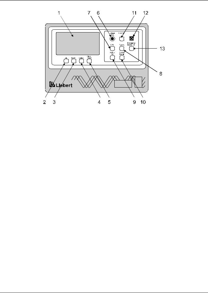
Figure 4 Series 610 UPS operator control panel
Item |
Description |
Function |
|
1 |
Display Screen |
This screen displays all vital UPS information in one convenient location. All of the UPS |
|
monitoring functions and conditions are indicated here. |
|||
|
|
||
|
|
This touch-sensitive pad (button) is used to move the cursor up through various |
|
2 |
Up |
selections present on the display screen. Note that all pads on this control panel have |
|
|
|
touch-sensitive switches behind them. |
|
3 |
Down |
Similar to the Up pad, this pad is used to move the cursor down through the various |
|
selections present on the display screen. |
|||
|
|
||
|
|
After using the Up and Down pads to move the highlighted cursor to the desired menu |
|
4 |
Select |
item on the display screen, push this pad to tell the microprocessor to go to the |
|
|
|
highlighted selection. |
|
|
|
This pad is used to clear all of the alarm conditions that are no longer present. However, |
|
5 |
Alarm Reset |
all active alarms remain in memory and on the applicable screens until they are |
|
|
|
corrected. |
|
|
|
This push-to-turn knob permits adjustment of the UPS output voltage to meet load |
|
6 |
Voltage Adjust |
requirements or to match the bypass voltage before transferring the load to or from |
|
|
|
bypass. |
|
|
|
This pad activates the circuits that connect the UPS inverter to the critical load (a |
|
7 |
UPS |
retransfer). When this pad is pushed (along with Control Enable), the UPS output circuit |
|
|
|
breaker closes and the bypass circuit breaker opens. |
|
|
|
This pad activates the circuits that connect the bypass line to the critical load (a |
|
8 |
Bypass |
transfer). When this button is pushed (along with Control Enable), the bypass circuit |
|
|
|
breaker closes and the UPS output circuit breaker opens. |
|
9 |
Battery Trip |
This pad can be used (along with Control Enable) to trip the module battery disconnect |
|
(MBD) circuit breaker open (disconnecting the battery from the UPS module). |
|||
|
|
||
10 |
Control Enable |
This pad must be pressed simultaneously with the UPS, Bypass or Battery Trip pads to |
|
activate them. |
|||
|
|
||
|
|
This pad is used to silence the alarm horn after it is activated. When this switch is |
|
11 |
Horn Off |
pressed, the alarm horn is silenced but the active and latched alarm messages remain |
|
on the screen. The alarm messages still displayed stop flashing to indicate they have |
|||
|
|
||
|
|
been acknowledged. |
|
|
|
|
|
12 |
Alarm Horn and Red LED |
This electronic horn sounds to alert nearby personnel whenever a new alarm occurs. A |
|
red LED (light emitting diode) is located in the middle of the alarm horn. |
|||
|
|
||
|
|
During an emergency, pressing this guarded switch will transfer the load to bypass and |
|
13 |
Emergency Module Off |
then shut down and disconnect the UPS inverter, rectifier and battery. The load will |
|
remain on bypass power. (Refer also to 3.4.4 - Shutdown Procedures for additional |
|||
|
|
||
|
|
performance options.) |
19

Operation
3.2Menu Tree Navigation
The Operator Interface Display is a blue-background display with white text. The display is always on, but the backlight will remain lit for 15 minutes following any display activation. After 15 minutes, the backlight will go out and the display may appear very dim. To reactivate the backlight, push any key. The backlight will again be active for 15 minutes after the last interaction or alarm. If any screen other than the mimic screen has been activated, after 5 minutes with no further interaction, the screen will revert to the basic mimic screen.
Figure 5 Menu tree
Master Menu
Monitor |
|
|
|
|
|
|
|
Status |
|
|
|
|
|
|
|
|
|
|
|
|
|
|
|
Start-Up |
|
|
|
|
|
|
|
|
|
|
|
Battery |
|||||||||||
Mimic |
|
|
|
|
|
|
|
|
|
|
|
Limit Settings |
|
|
|
|
|
|
Battery Time |
|
|
|
|||||||||||||||||||||||||
|
|
|
|
|
|
Reports |
|
|
|
|
|
|
|
|
Procedures |
|
|
|
|
|
Equalize |
||||||||||||||||||||||||||
Display |
|
|
|
|
|
|
|
|
|
|
|
|
|
|
|
|
|
|
|
|
|
|
|
|
|
|
|
|
|
|
|
|
|||||||||||||||
|
|
|
|
|
|
|
|
|
|
|
|
|
|
|
|
|
|
|
|
|
|
|
|
|
|
|
|
|
|
|
|
|
|
|
|
|
|
|
|
|
|
|
|
||||
|
|
|
|
|
|
|
|
|
|
|
|
|
|
|
|
|
|
|
|
|
|
|
|
|
|
|
|
|
|
|
|
|
|
|
|
|
|
|
|
|
|
|
|
|
|
||
|
|
|
|
Walk-In |
|
|
|
|
|
System |
|
|
|
|
|
Load |
|
|
|
Shutdown |
|
|
|
Meter |
|
|
|
||||||||||||||||||||
|
|
|
|
|
|
|
|
Configura- |
|
|
|
|
|
|
|
|
|
|
|
|
|
|
|||||||||||||||||||||||||
|
|
|
|
Display |
|
|
|
|
|
|
|
|
Transfer |
|
|
|
Procedures |
|
|
|
Calibration |
|
|
||||||||||||||||||||||||
|
|
|
|
|
|
|
|
|
|
tion |
|
|
|
|
|
|
|
|
|
|
|
|
|||||||||||||||||||||||||
|
|
|
|
|
|
|
|
|
|
|
|
|
|
|
|
|
|
|
|
|
|
|
|
|
|
|
|
|
|
|
|
|
|
|
|
|
|
|
|
|
|
|
|
||||
|
|
|
|
|
|
|
|
|
|
|
|
|
|
|
|
|
|
|
|
|
|
|
|
|
|
|
|
|
|
|
|
|
|
|
|
|
|
|
|
|
|
|
|
||||
|
|
|
Present |
|
|
|
|
|
|
|
|
|
|
Date |
|
|
|
|
|
|
|
|
|
|
|
|
|
|
|
|
|
|
|
|
|
|
|
|
|||||||||
|
|
|
Status |
|
|
|
|
|
|
|
|
|
|
|
|
|
|
|
|
|
|
|
|
|
|
|
|
|
|
|
|
|
|
|
|
|
|
|
|
||||||||
|
|
|
|
|
|
|
|
|
|
|
|
|
|
|
|
|
|
|
|
|
|
|
|
|
|
|
|
|
|
|
|
|
|
|
|
|
|
|
|
|
|
|
|||||
|
|
|
|
|
|
|
|
|
|
|
|
|
|
|
|
|
|
|
|
|
|
|
|
|
|
|
|
|
|
|
|
|
|
|
|
|
|
|
|
|
|
||||||
|
|
|
|
|
|
|
|
|
|
|
|
|
|
|
|
|
|
|
|
|
|
|
|
|
|
|
|
|
|
|
|
|
|
|
|
|
|
|
|
|
|
|
|
|
|
|
|
|
|
Event History |
|
|
|
|
|
|
|
|
|
|
Time |
|
|
|
|
|
|
|
|
|
|
|
|
|
|
|
|
|
|
|
|
|
|
|
|
||||||||||
|
|
|
|
|
|
|
|
|
|
|
|
|
|
|
|
|
|
|
|
|
|
|
|
|
|
|
|
|
|
|
|
|
|
|
|
|
|
|
|
|
|
|
|
|
|
||
|
|
|
|
|
|
|
|
|
|
|
|
|
|
|
|
|
|
|
|
|
|
|
|
|
|
|
|
|
|
|
|
|
|
|
|
|
|
|
|
|
|
|
|
|
|
|
|
|
|
|
History |
|
|
|
|
|
|
|
|
|
|
|
|
Auto Dial |
|
|
|
|
|
|
|
|
|
|
|
|
|
|
|
|
|
|
|
|
|
|
|||||||||
|
|
|
Status |
|
|
|
|
|
|
|
|
|
|
|
|
|
|
|
|
|
|
|
|
|
|
|
|
|
|
|
|
|
|
|
|
|
|||||||||||
|
|
|
|
|
|
|
|
|
|
|
|
|
|
|
|
|
|
|
|
|
|
|
|
|
|
|
|
|
|
|
|
|
|
|
|
|
|
|
|
|
|
|
|||||
|
|
|
|
|
|
|
|
|
|
|
|
|
|
|
|
|
|
|
|
|
|
|
|
|
|
|
|
|
|
|
|
|
|
|
|
|
|
|
|
|
|
|
|
|
|||
|
|
|
|
|
|
|
|
|
|
|
|
|
|
|
|
|
|
|
|
|
|
|
|
|
|
|
|
|
|
|
|
|
|
|
|
|
|
|
|
|
|
|
|
|
|
|
|
|
|
|
System |
|
|
|
|
|
|
|
|
|
|
|
|
Lang. |
|
|
|
|
|
|
|
|
|
|
|
|
|
|
|
|
|
|
|
|
|
|
|
|
|||||||
|
|
|
Status |
|
|
|
|
|
|
|
|
|
|
|
|
Selection |
|
|
|
|
|
|
|
|
|
|
|
|
|
|
|
|
|
|
|
|
|
||||||||||
|
|
|
|
|
|
|
|
|
|
|
|
|
|
|
|
|
|
|
|
|
|
|
|
|
|
|
|
|
|
|
|
|
|
|
|
|
|
|
|
|
|
|
|
|
|
|
|
|
|
|
|
|
|
|
|
|
|
|
|
|
|
|
|
|
|
|
|
|
|
|
|
|
|
|
|
|
|
|
|
|
|
|
|
|
|
|
|
|
|
|
|
|
|
|
|
|
|
|
|
|
|
|
|
|
|
|
|
|
|
|
|
|
|
|
|
System |
|
|
|
|
|
|
|
|
|
|
|
|
|
|
|
|
|
|
|
|
|
|
|
|
|||
|
|
Battery Cycle |
|
|
|
|
|
|
|
|
|
|
|
|
|
|
|
|
|
|
|
|
|
|
|
|
|
|
|
|
|
|
|
|
|
|
|||||||||||
|
|
|
|
|
|
|
|
|
|
|
|
Options |
|
|
|
|
|
|
|
|
|
|
|
|
|
|
|
|
|
|
|
|
|
|
|
|
|||||||||||
|
|
|
Monitor |
|
|
|
|
|
|
|
|
|
|
|
|
|
|
|
|
|
|
|
|
|
|
|
|
|
|
|
|
|
|
|
|
|
|
||||||||||
|
|
|
|
|
|
|
|
|
|
|
|
|
|
|
|
|
|
|
|
|
|
|
|
|
|
|
|
|
|
|
|
|
|
|
|
|
|
|
|
|
|||||||
|
|
|
|
|
|
|
|
|
|
|
|
|
|
|
|
|
|
|
|
|
|
|
|
|
|
|
|
|
|
|
|
|
|
|
|
|
|
|
|
|
|||||||
|
|
|
|
|
|
|
|
|
|
|
|
|
|
|
|
|
|
|
|
|
|
|
|
|
|
|
|
|
|
|
|
|
|
|
|
|
|
|
|
||||||||
|
|
|
|
|
|
|
|
|
|
|
|
|
|
|
|
|
|
|
|
|
|
|
|
|
|
|
|
|
|
|
|
|
|
|
|
|
|
|
|
|
|
|
|
|
|
|
|
|
|
|
|
|
|
|
|
|
|
|
|
|
|
|
|
|
|
|
|
|
|
|
|
|
|
|
|
|
|
|
|
|
|
|
|
|
|
|
|||||||||
|
|
|
|
|
|
|
|
Backlight |
|
|
Customer |
|
|
Battery |
|
|
Batt. Temp. |
|
|
|
|
|
|
|
|
|
Continuous |
||||||||||||||||||||
LCD Contrast |
|
|
|
|
|
|
Alarm |
|
|
|
|
|
|
Charging |
|
|
Auto Restart |
|
|
Duty Static |
|||||||||||||||||||||||||||
|
|
|
Brightness |
|
|
|
|
|
|
Exercise |
|
|
|
|
|
|
|||||||||||||||||||||||||||||||
|
|
|
|
|
|
|
|
|
Definitions |
|
|
|
|
|
Compensation |
|
|
|
|
|
|
|
|
|
Switch |
||||||||||||||||||||||
|
|
|
|
|
|
|
|
|
|
|
|
|
|
|
|
|
|
|
|
|
|
|
|
|
|
|
|
|
|
|
|
|
|
||||||||||||||
20

Operation
Figure 5 illustrates the primary screens that you can access through the Operator Interface Display System. The liquid crystal display (LCD) screen provides a full 80 characters by 25 lines of information for easy readability. The following sections describe what these screens display and how and when to use them.
System status information is available on the display screen and at local and remote terminals, provided Control Power is ON, even when the UPS module is not operating.
The screen will automatically display the Monitor/Mimic during normal operation. The System configuration screen will be displayed during start-up and whenever a system reset is required.
If a module display screen is blank, either power is not available, the Rectifier Input (RIB) circuit breaker (external to the UPS module) is open or the Control Power switch is OFF. If power is available and a display is blank, contact Liebert Global Services (1-800-LIEBERT). Note that status information may be available at local and remote terminals. Use control touch pads to manually transfer the critical load to the bypass line if the display goes blank while load is on UPS (a very unlikely event).
3.2.1Master Menu Screen
The Master Menu contains the primary menu selections that monitor and control the operation of the UPS.
Figure 6 Master menu screen
|
|
|
UP : CURSOR UP |
|
|
|
|
|
© 1989-2003 |
DOWN : CURSOR DOWN |
|
|
|
||
|
SELECT : CHOOSE |
||
|
|
|
|
|
MASTER MENU |
|
|
|
|
||
MONITOR/MIMIC DISPLAY |
START-UP PROCEDURES |
||
WALK-IN DISPLAY |
|
SHUTDOWN PROCEDURES |
|
STATUS REPORTS |
|
BATTERY TIME |
|
SYSTEM CONFIGURATION |
METER CALIBRATION |
||
LIMIT SETTINGS |
|
BATTERY EQUALIZE |
|
LOAD TRANSFER PROCEDURES |
CUSTOMER ALARM DEFINITIONS |
||
|
|
BATTERY TEST |
|
|
|
BATTERY TEMP COMP. CHARGING |
|
Up |
|
|
Alarm |
Down |
Select |
Reset |
|
From any primary screen (accessed directly from the Master Menu), pushing the Select pad once will return you to the Master Menu. From any secondary screen, pushing the Select pad twice will return you to the Master Menu.
Please note that some screens have multiple pages. However, in each case, instructions appear for accessing other pages.
•Monitor/Mimic Display—This graphic mimics the power flow through the UPS. Input voltage and current readings, battery status, UPS ratings, load readings, circuit breaker indications, system status and alarm messages are all displayed on this screen.
•Walk-In Display—This is a bar graph that shows DC bus voltage, input currents and UPS module output voltage (all in percent of nominal). This screen typically is utilized during start-up procedures.
•Status Reports—This display consists of four submenu selections: present status, event history, history status and system status. These screens display data on the system’s present and past performance. They also display information about any faults that have occurred in the system. Total operating hours (for controls) are displayed here.
21

Operation
•System Configuration—This screen displays the current configuration of the UPS system. It also enables the operator to reset the date, time, dial-out phone numbers and System Options. System Options include Temperature-Compensated Charging, Customer Alarm Definitions, Auto Restart and Battery Load Test. The operator can view, but cannot change, any of the settings unless the Interlock (Security Access) button is pressed.
•Limit Settings—This security access display shows the present UPS system alarm limit settings. The operator can view the settings, but they should not be changed without consulting Liebert Global Services.
•Load Transfer Procedures—This screen specifies all of the steps required to manually transfer the critical load between the UPS and the bypass source. Comparisons of the voltage, frequency and phase synchronization of the UPS output and the bypass line are also illustrated to aid in the transfer or retransfer procedure.
•Start-Up Procedures—This two-page screen lists step-by-step procedures to start the UPS.
•Shutdown Procedures—This two-page screen lists the proper sequence of steps to shutdown the UPS for maintenance or repairs. The steps instruct the operator to transfer the critical load to bypass, open the battery circuit breakers and open the UPS input circuit breakers to shut down and isolate the system. The critical load will remain on bypass power unless circuit breakers outside the UPS are also opened.
•Battery Time—This graph displays the projected battery voltage drop caused by a battery discharge over time. During a period of battery discharge, the Series 610 calculates the battery time remaining based on battery rating, initial battery condition and actual connected load. The UPS continues to update and display both rated (theoretical) and calculated time every 6 seconds. This enables the operator to immediately see the effects of load shedding on time remaining and to accurately assess his power resources.
•Meter Calibration—This security access screen enables an authorized Liebert field-service engineer to adjust and calibrate the UPS metered functions. The operator can view, but should not change, any of the settings.
•Battery Equalize—The battery equalize screen lets the operator change the battery equalize recharging mode from manual to automatic and to observe or change the equalize time. Battery equalize charge voltage is higher than battery float charge voltage.
NOTE
Do not use battery equalize charging with sealed-cell (VRLA) batteries. Refer to the battery manufacturer’s manual, available on the manufacturer’s Web site, for specific information about equalize charging.
•Customer Alarm Definitions—This optional screen allows the operator to define alarms for conditions external to the UPS, battery or switchgear.
•Battery Test (Optional)—The battery test screen allows the operator to perform manual battery tests to determine the general condition of the battery system. The results of the last 10 tests are recorded in non-volatile storage and can be retrieved through the battery test results screen.
•Battery Temp Compensation Charging (Optional)—The optional battery temperature sensing unit, when installed, automatically reduces the float charge voltage in response to increases in battery temperature. The nominal float voltage is 540VDC (2.25 volts per cell) at 25°C. This float voltage is automatically reduced 5VDC for each temperature rise of 5°C. The LCD indicates whether the temperature compensation circuit is active.
22

Operation
3.2.2Monitor/Mimic Display Screen
From Master Menu move the highlighted cursor to MONITOR/MIMIC DISPLAY. Press the Select pad and the Monitor/Mimic screen is displayed.
Figure 7 Monitor/Mimic display screen
|
|
1 |
© 1989-2003 |
|||
BYPASS INPUT |
||||||
A-B B-C C-A |
|
|
|
|||
480V |
480V |
480V |
|
|
|
|
|
60.0 Hz |
2 |
|
|
4 |
|
|
|
|
|
|||
|
|
UPS RATINGS |
||||
UPS INPUT PWR |
AP658-64 |
|
||||
RATED 500 KVA |
||||||
A-B |
B-C |
C-A |
||||
OUTPUT VOLTAGE |
||||||
480V |
480V |
480V |
||||
A-B |
B-C |
C-A |
||||
350A |
350A 350A |
|||||
|
|
3 |
480V |
480V |
480V |
|
|
|
|
|
60.0 Hz |
6 |
|
BATTERY |
|
|
||||
VOLTS 540 
 AMPS 15 CHARG OK to Transfer
Static Switch Connected
5 |
|
|
|
LOAD |
|
270 KVA / 217 KW |
||
A |
B |
C |
325A |
325A |
325A |
7 |
|
|
The Monitor/Mimic display screen is a simplified block diagram of the UPS system. This screen gives the operator an overall view of the power flow through the UPS system. The screen consists of three major sections: the input/UPS metering section, the load metering section and the status and alarm message areas. The metered parameter values on the Monitor/Mimic screen are updated at one-sec- ond intervals.
NOTE
All voltage readings are phase-to-phase measurements (A-B, B-C and C-A). All current readings are phase measurements (A, B and C).
Input Metering Displays
Item 1 - Bypass Input: This block displays the bypass input voltage and the bypass input frequency. The bypass circuit breaker is shown to the right of this block. The status of the circuit breaker is illustrated as open or closed.
Item 2 - UPS Input Pwr: This block displays the UPS input voltage and current. The input circuit breaker is shown to the right of this block. The status of the circuit breaker is illustrated as open or closed.
Item 3 - Battery Block: This block displays the DC bus voltage and the charge or discharge current to or from the battery. This block reads MODULE DC BUS when the battery circuit breaker is open and BATTERY when the battery circuit breaker is closed during normal operation. This block reads BATTERY EQUALIZE when the battery equalize charge voltage is used to recharge the battery. This block also shows BATTERY TEMPERATURE when the battery temperature sensor option is installed. The Module Battery Disconnect (MBD) is shown to the right of this block. The status of the circuit breaker is illustrated as open or closed.
Output Metering Displays
Item 4 - UPS Ratings: This block displays the UPS module part number and kVA rating. The UPS output voltage and frequency are also displayed in this block. The output circuit breaker is shown to the right of this block. The status of the circuit breaker is illustrated as open or closed.
Item 5 - Load: This block displays the total output power to the critical load in kVA and kW. The critical load current per phase is also displayed in this block. Note that kW is not displayed when the load is on the bypass line. During an overload condition, the time remaining before transfer is displayed at the bottom of the load box.
23

Operation
Status/Alarm Message Areas
The status/alarm message areas display vital information about the operation of the UPS system. During normal operation no alarm messages should be present. Changes in the status of the system and possible alarm conditions can be monitored. Both the status and the alarm messages are displayed in reverse video (highlighted—light on dark). The alarm messages continue flashing until the Horn Off pad is pressed. To clear a latching alarm, you must also press the Alarm Reset pad after the alarm condition is corrected.
The following lists show the status and alarm messages that may be displayed in these areas. For more information and the corrective actions for these messages, refer to Table 4 in this section.
Item 6 - Status Messages
Static Switch Connected Static Switch Disconnected OK To Transfer
Not OK To Transfer
Item 7 - Alarm Messages |
|
Input Fail |
Output Over/Underfrequency |
DC Ground Fault |
Output Undervoltage |
DC Capacitor Fuse Blown |
Output Overvoltage |
Battery CB Open |
Overload |
Battery Discharging |
Overload Transfer |
Low Battery Warning |
Inverter Non-Sync |
Low Battery Shutdown |
Reverse Power |
DC Overvoltage Shutdown |
Rectifier Fuse Blown |
Load On Bypass |
Inverter Fault |
Auto Retransfer Primed |
Hardware Shutdown |
Manual Reset/Retransfer |
Emergency Off |
Static Switch Unable |
Battery Cycle Buffer Warning |
Bypass Not Available |
Ambient Overtemperature |
Bypass Phase Sequence Wrong |
Blower Failed |
Control Power Fail |
Equipment Overtemperature |
Battery Overtemp |
Overtemperature Time-out |
Battery Exercise |
|
Figures 8 through 11 illustrate how the Monitor/Mimic Display screens depict the power flow through the UPS.
Figure 8 Monitor/Mimic display example: Normal power flow
BYPASS INPUT |
||
A-B B-C C-A |
||
480V |
480V |
480V |
|
60.0 Hz |
|
UPS INPUT PWR |
||
A-B |
B-C C-A |
|
480V |
480V |
480V |
350A 350A 350A |
||
BATTERY
VOLTS 540
AMPS 15 CHARG
© 1989-2003
UPS RATINGS |
||
|
AP658-64 |
|
RATED 500 KVA |
||
OUTPUT VOLTAGE |
||
A-B B-C C-A |
||
480V |
480V |
480V |
|
60.0 Hz |
|
OK to Transfer
Static Switch Connected
|
LOAD |
|
270 KVA / 217 KW |
||
A |
B |
C |
325A |
325A |
325A |
24
Loading...