

LG NB3732A Owner Manual

OWNER’S MANUAL
300 W SMART SOUND
BAR
Please read this manual carefully before operating your set and retain it
for future reference.
NB3730A (NB3730A, S33A1-D)
NB3732A (NB3732A, S33A1-D)
www.lg.com

Getting Started 3
Safety Information
CAUTION
RISK OF ELECTRIC SHOCK
DO NOT OPEN
CAUTION: TO REDUCE THE RISK OF ELECTRIC
SHOCK DO NOT REMOVE COVER (OR BACK) NO
USER-SERVICEABLE PARTS INSIDE REFER SERVICING
TO QUALIFIED SERVICE PERSONNEL.
This lightning ash with
arrowhead symbol within an
equilateral triangle is intended to
alert the user to the presence of
uninsulated dangerous voltage
within the product’s enclosure
that may be of sucient
magnitude to constitute a risk of
electric shock to persons.
The exclamation point within an
equilateral triangle is intended
to alert the user to the presence
of important operating and
maintenance (servicing)
instructions in the literature
accompanying the product.
WARNING: This product contains chemicals known
to the State of California to cause cancer and birth
defects or other reproductive harm. Wash hands
after handling.
WARNING: TO PREVENT FIRE OR ELECTRIC SHOCK
HAZARD, DO NOT EXPOSE THIS PRODUCT TO RAIN
OR MOISTURE.
CAUTION: The apparatus shall not be exposed to
water (dripping or splashing) and no objects lled
with liquids, such as vases, shall be placed on the
apparatus.
WARNING: Do not install this equipment in a
conned space such as a book case or similar unit.
CAUTION: Do not block any ventilation openings.
Install in accordance with the manufacturer’s
instructions.
Slots and openings in the cabinet are provided for
ventilation and to ensure reliable operation of the
product and to protect it from over heating. The
openings shall be never be blocked by placing
the product on a bed, sofa, rug or other similar
surface. This product shall not be placed in a builtin installation such as a bookcase or rack unless
proper ventilation is provided or the manufacturer’s
instruction has been adhered to.
CAUTION concerning the Power Cord
Most appliances recommend they be placed upon
a dedicated circuit;
That is, a single outlet circuit which powers only
that appliance and has no additional outlets or
branch circuits. Check the specication page of this
owner’s manual to be certain. Do not overload wall
outlets. Overloaded wall outlets, loose or damaged
wall outlets, extension cords, frayed power cords, or
damaged or cracked wire insulation are dangerous.
Any of these conditions could result in electric
shock or re. Periodically examine the cord of your
appliance, and if its appearance indicates damage
or deterioration, unplug it, discontinue use of the
appliance, and have the cord replaced with an
exact replacement part by an authorized service
center. Protect the power cord from physical or
mechanical abuse, such as being twisted, kinked,
pinched, closed in a door, or walked upon. Pay
particular attention to plugs, wall outlets, and
the point where the cord exits the appliance. To
disconnect power from the mains, pull out the
mains cord plug. When installing the product,
ensure that the plug is easily accessible.
1
Getting Started

Getting Started4
This device is equipped with a portable battery or
accumulator.
Safety way to remove the battery from the
equipment: Remove the old battery or battery
1
pack, follow the steps in reverse order than
Getting Started
the assembly. To prevent contamination of the
environment and bring on possible threat to
human and animal health, the old battery or
the battery put it in the appropriate container
at designated collection points. Do not dispose
of batteries or battery together with other
waste. It is recommended that you use local,
free reimbursement systems batteries and
accumulators. The battery should not be exposed
to excessive heat such as sunshine, re or the like.
IMPORTANT SAFETY
INSTRUCTIONS
1. Read these instructions.
2. Keep these instructions.
3. Heed all warnings.
4. Follow all instructions.
5. Do not use this apparatus near water.
6. Clean only with dry cloth.
7. Do not block any ventilation openings.
Install in accordance with the manufacturer’s
instructions.
8. Do not install near any heat sources such
as radiators, heat registers, stoves, or other
apparatus (including amplifiers) that produce
heat.
9. Do not defeat the safety purpose of the
polarized or grounding-type plug. A polarized
plug has two blades with one wider than the
other. A grounding type plug has two blades
and a third grounding prong. The wide blade or
the third prong are provided for your safety. If
the provided plug does not fit into your outlet,
consult an electrician for replacement of the
obsolete outlet.
10. Protect the power cord from being walked on
or pinched particularly at plugs, convenience
receptacles, and the point where they exit from
the apparatus.
11. Only use attachments/accessories specified by
the manufacturer.
12. Use only with the cart, stand, tripod, bracket, or
table specified by the manufacturer, or sold with
the apparatus. When a cart is used, use caution
when moving the cart/apparatus combination
to avoid injury from tip-over.
13. Unplug this apparatus during lightning storms
or when unused for long periods of time.
14. Refer all servicing to qualified service personnel.
Servicing is required when the apparatus has
been damaged in any way, such as powersupply cord or plug is damaged, liquid has been
spilled or objects have fallen into the apparatus,
the apparatus has been exposed to rain or
moisture, does not operate normally, or has
been dropped.

Getting Started 5
FCC Compliance Statement
This device complies with part 15 of the FCC
rules. Operation is subject to the following two
conditions:
(1) This device may not cause harmful interference,
and
(2) This device must accept any interference
received, including interference that may cause
undesired operation.
NOTE: This equipment has been tested and found
to comply with the limits for a Class B digital device,
pursuant to Part 15 of the FCC Rules. These limits are
designed to provide reasonable protection against
harmful interference in a residential installation. This
equipment generates, uses, and can radiate radio
frequency energy and, if not installed and used
in accordance with the instructions, may cause
harmful interference to radio communications.
However, there is no guarantee that interference
will not occur in a particular installation.
If this equipment does cause harmful interference
to radio or television reception, which can be
determined by turning the equipment o and
on, the user is encouraged to try to correct the
interference by one or more of the following
measures:
yReorient or relocate the receiving antenna.
yIncrease the separation between the equipment
and receiver.
yConnect the equipment into an outlet on a
circuit dierent from that to which the receiver is
connected.
yConsult the dealer or an experienced radio/TV
technician for help.
CAUTION: Any changes or modications not
expressly approved by the party responsible for
compliance could void the user’s authority to
operate this equipment.
FCC RF Radiation Exposure Statement : This
equipment complies with FCC radiation exposure
limits set forth for an uncontrolled environment.
This equipment should be installed and operated
with minimum distance 20 cm between the
radiator and your body. End users must follow the
specic operating instructions for satisfying RF
exposure compliance. This transmitter must not be
co-located or operating in conjunction with any
other antenna or transmitter.
FCC Radio Frequency Interference
Requirements
This device is restricted to indoor use due to its
operation in the 5.15 to 5.25 GHz frequency range.
FCC requires this product to be used indoors for
the frequency range 5.15 to 5.25 GHz to reduce the
potential for harmful interference to co-channel
Mobile Satellite systems. High power radars are
allocated as primary users of the 5.25 to 5.35 GHz
and 5.65 to 5.85 GHz bands. These radar stations
can cause interference with and/or damage this
device. This device cannot be co-located with any
other transmitter.
CAUTION: Regulations of the FCC and FAA prohibit
airborne operation of radio-frequency wireless
devices because their signals could interfere with
critical aircraft instruments.
Responsible Party :
LG Electronics USA, Inc.1000 Sylvan Avenue
Englewood Clis, NJ 07632
TEL. : +1-800-243-0000
1
Getting Started

Table of Contents6
Table of Contents
1 Getting Started
3 Safety Information
8 Introduction
8 – About the “7” symbol display
9 Front Panel
9 Rear Panel
10 Remote Control
11 Mounting the main unit on a wall
2 Connecting
13 Speaker Connection
13 – Pairing wireless subwoofer
14 Connecting to Your TV
14 – HDMI Connection
14 – What is SIMPLINK?
15 – ARC (Audio Return Channel) function
15 – Resolution Setting
16 – Optical digital audio connection
17 Connections with external device
17 – OPTICAL IN connection
17 Connecting to your Home Network
17 – Wired network connection
18 – Wired network setup
19 – Wireless network connection
20 – Wireless network setup
3 System Setting
23 Initial Setup
24 Settings
24 – Adjust the setup settings
25 – [NETWORK] menu
26 – [DISPLAY] menu
27 – [LANGUAGE] menu
28 – [AUDIO] menu
29 – [OTHERS] menu
30 Sound Effect
4 Operating
31 Home Menu Display
31 – Using [HOME] menu
31 – Using the Smart Share
32 Playing the Linked Devices
32 – Playing a USB device
33 – Playing a file on a network server
34 Using Home Network Server for PC
34 – Installing Nero MediaHome 4
Essentials
34 – Sharing files and folders
35 – About Nero MediaHome 4 Essentials
35 – System requirements
36 General Playback
36 – Basic operations for video and audio
content
36 – Basic operations for photo content
37 – Resume playback
38 On-Screen Display
38 – To control video playback
39 – To control photo view
40 Viewing information from Gracenote
Media Database
41 Advanced Playback
41 – Repeat playback
41 – Repeating a specific portion
41 – Playing from selected time
42 – Selecting a subtitle language
42 – Hearing a different audio
42 – Changing the TV Aspect Ratio
43 – Changing Subtitle Code Page
43 – Changing the Picture Mode
43 – Viewing content information
44 – Changing content list view
44 – Selecting a subtitle file
45 – Listening to music during slide show
45 – Setting the [3D] option
46 Advanced Features
46 – Wi-Fi Direct™
47 Using Bluetooth technology
47 – Listening to music stored on the
Bluetooth devices
48 Using the Premium
49 Using the LG Smart World
49 – Signing in
50 – Searching online content

50 Using the My Apps Menu
5 Troubleshooting
51 Troubleshooting
51 – General
52 – Network
53 – Picture
53 – Sound
53 – Customer Support
53 – Open Source Software Notice
Table of Contents 7
1
2
6 Appendix
54 Controlling a TV with the Supplied
Remote Control
54 – Setting up the remote to control your
TV
55 Network Software Update
55 – Network update notification
55 – Software update
57 Additional Information
57 – File requirement
59 – About DLNA
59 – Certain system requirements
60 Audio Output Specifications
61 Trademarks and Licenses
64 Specifications
65 Maintenance
65 – Handling the unit
65 Important Information relating to Network
Services
3
4
5
6
Some of the content in this manual may dier from your unit depending on the software of the
unit or your service provider.

Getting Started8
Introduction
1
Getting Started
Term Symbol Description
Indicates special
Note
Caution
,
>
notes and operating
features.
Indicates cautions
for preventing
possible damages
from abuse.
About the “7” symbol display
“7” may appear on your TV display during
operation and indicates that the function explained
in this owner’s manual is not available on that
specic media.
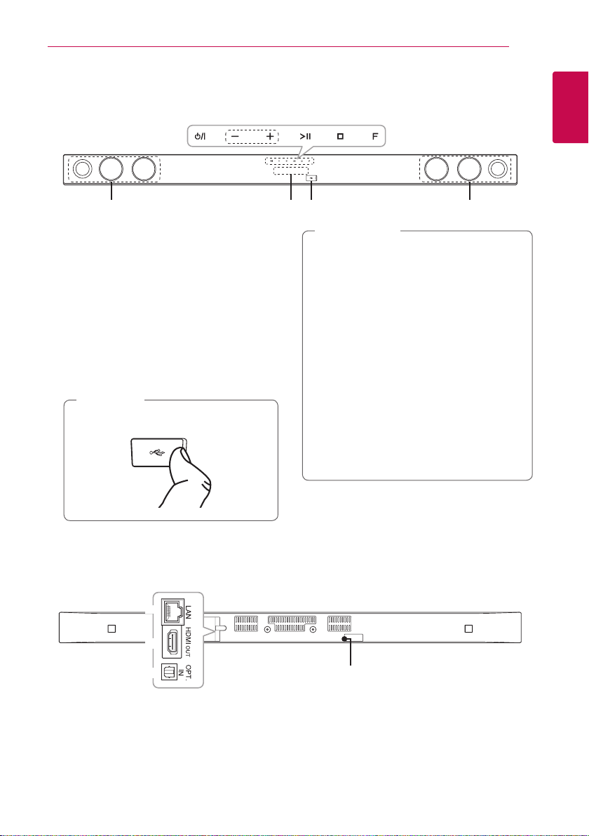
Front Panel
a b c d e
f g h f
a 1/!
b
c T
d I
e
f
g
h
(Standby/On)
– / + (Volume)
Adjusts speaker volume.
(Play / Pause)
(Stop)
F (Function)
Press it repeatedly to select other function.
Speakers
Display window
USB Port
Note
,
Open USB cover by using your nger to
connect USB.
Getting Started 9
Caution
>
Precautions in using the touch buttons
yUse the touch buttons with clean and dry
hands.
- In a humid environment, wipe out any
moisture on the touch buttons before
using.
yDo not press the touch buttons hard to
make it work.
- If you apply too much strength, it can
damage the sensor of the touch buttons.
yTouch the button that you want to work in
order to operate the function correctly.
yBe careful not to have any conductive
material such as metallic object on the
touch buttons. It may cause the unit to
malfunction.
1
Getting Started
Rear Panel
a
b
c
LAN connector
a
HDMI OUT connector
b
d
OPT. IN connector
c
DC IN connector
d
Getting Started10
10
Remote Control
1
1
Getting Started
Getting Started
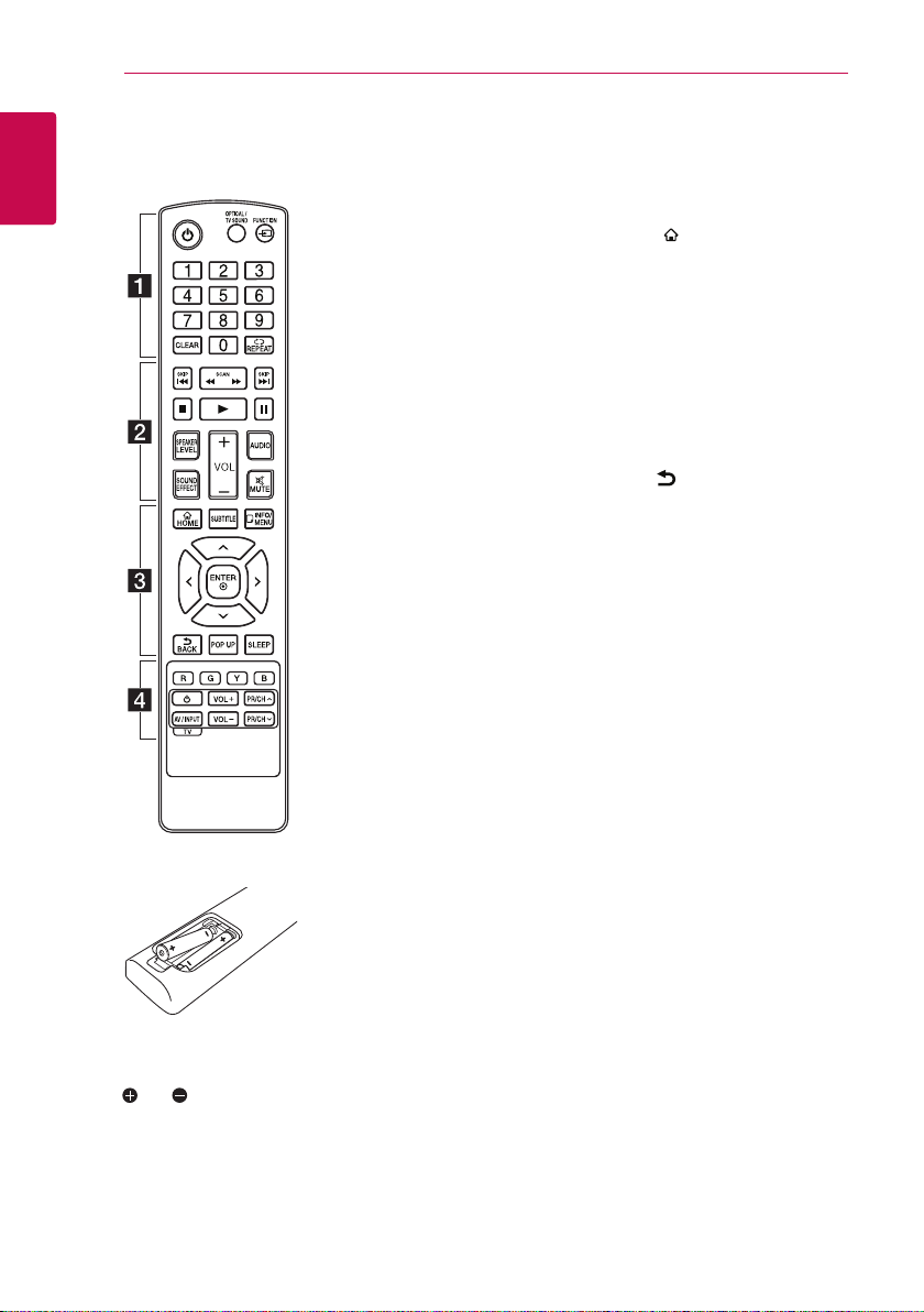
Battery Installation
• • • • • • a • • • • • •
(Power): Switches the unit ON
1
or OFF.
OPTICAL/TV SOUND:
Changes input mode to optical
directly.
FUNCTION (P): Changes input
mode.
0-9 numerical buttons: Selects
numbered options in a menu.
CLEAR: Removes a mark on the
search menu or a number when
setting the password.
REPEAT (h): Repeats a desired
section or sequence.
• • • • • • b • • • • •
c/v
backward or forward.
C/V
next or previous chapter/title/le.
Z
z
M
SPEAKER LEVEL: Sets the sound
level of desired speaker.
SOUND EFFECT: Selects a sound
eect mode.
VOL +/-: Adjusts speaker volume.
AUDIO: Selects an audio language
or audio channel.
MUTE(@): Mute the unit.
(SCAN): Searches
(SKIP): Goes to the
(Stop): Stops playback.
(Play): Starts playback.
(Pause): Pauses playback.
• • • • • • c • • • • •
HOME ( ): Displays or exits the
[Home Menu].
SUBTITLE: Selects a subtitle
language.
INFO/MENU (m): Displays or exits
On-Screen Display.
Direction buttons: Selects an
option in the menu.
ENTER (b): Acknowledges menu
selection.
BACK ( ): Exits the menu or
resumes playback.
POP UP: Displays a pop-up menu,
if available.
SLEEP: Sets the system to turn off
automatically at a specified time.
• • • • • • d • • • • •
Colored (R, G, Y, B) buttons:
They are used as shortcut buttons
for specic menus.
TV Control Buttons: See page
54.
Remove the battery cover on the
rear of the Remote Control, and
insert two R03 (size AAA) battery
with and matched correctly.
Getting Started 11
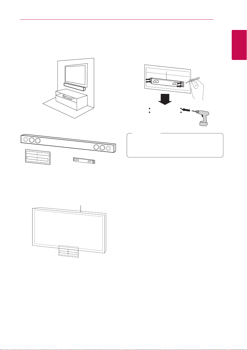
Mounting the main unit on a wall
You can mount the main unit on a wall.
Prepare screws and bracket.
Unit
Wall Mount Bracket
Installation Template
1. Match the TV’s BOTTOM EDGE of Wall Mount
Bracket Installation Template with the bottom
of TV and attach to the position.
Wall bracket
TV
2. When you mount it on a wall (concrete), use
the wall plugs (Not supplied). You should drill
some holes. A guide sheet (Wall Mount Bracket
Installation Template) is supplied to drill. Use the
sheet to check the point to drill.
Note
,
Screws and Wall Plugs are not supplied for
mounting the unit. We recommend the Hilti
(HUD-1 6 x 30) for the mounting.
1
Getting Started
Getting Started12
3. Remove the Wall Mount Bracket Installation
Template.
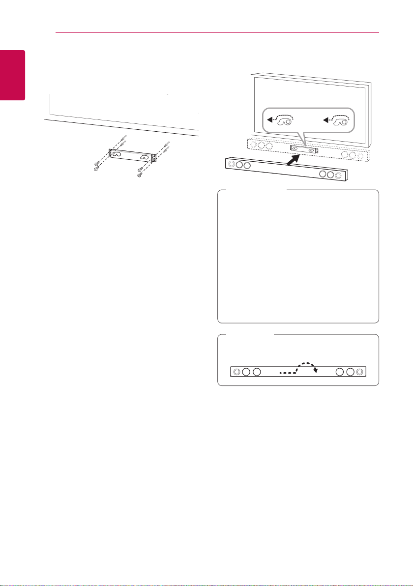
4. Fix it with screws (not supplied) as shown in the
illustration below.
1
Getting Started
5. Hang the main unit onto the bracket as shown
below.
Caution
>
yDo not install this unit upside down. It can
damage the parts of this unit or be the
cause of personal injury.
yDo not hang onto the installed unit and
avoid any impact to the unit.
ySecure the unit rmly to the wall so that it
does not fall o. If the unit falls o, it may
result in an injury of a person or damage to
the product.
yWhen the unit is installed on a wall, please
make sure that a child does not pull any of
connecting cables, as it may cause it to fall.
Note
,
Detach the unit from the bracket as shown
below.

Speaker Connection
Pairing wireless subwoofer
LED indicator of wireless subwoofer
LED Color Status
Yellow-green The wireless subwoofer is
Yellow-green
(blink)
Red The Wireless subwoofer is in
O (No
display)
Setting up the wireless subwoofer
for the first time
1. Connect the power cord of the Wireless
subwoofer to the outlet.
2. Turn on the main unit : The main unit and
wireless subwoofer will be automatically
connected.
receiving the signal of the unit.
The wireless subwoofer is trying
to connect.
standby mode.
The power cord of wireless
subwoofer is disconnected.
Connecting 13
Note
,
yIf there is a strong electromagnetic wave
product nearby, interference may occur. Put
the unit (Wireless subwoofer and main unit)
away from there.
yIf you operate main unit then wireless
subwoofer sound within a few seconds in
standby mode.
ySet the distance between this unit and
subwoofer Receiver within 10 m (32 ft.).
yOptimum performance can be
implemented only when the unit and
the Wireless subwoofer within distance
of 2 m (6 ft.) to 10 m (32 ft.) is used since
communication failure may occur if longer
distance is used.
yIt takes a few seconds (and may take longer)
for the Wireless Transmitter and subwoofer
to communicate with each other.
13
2
Connecting
Manually pairing wireless subwoofer
When your connection is not completed, you can
see the red LED on the woofer and woofer is not
made sound. To solve the problem, follow the
below steps.
1. Press and hold Z (Stop) button on the unit
and MUTE button on the remote control
simultaneously.
- Displays the “REMATE”.
2. Press PAIRING on back of the woofer.
- The Yellow-green LED will flicker.
3. Turn off and on the unit.
- If you see “Yellow-green” LED, it’ s successful.
4. If you don’t see “Yellow-green” LED, try again
Step 1 - Step 3.
Connecting14
Connecting to Your TV
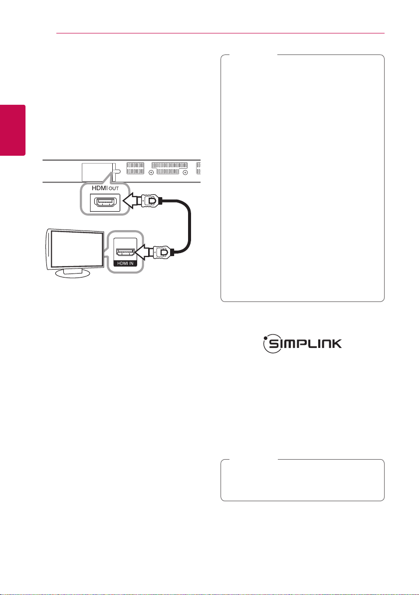
HDMI Connection
If you have a HDMI TV or monitor, you can connect
it to this unit using a HDMI cable (Type A, High
speed HDMI™ cable with Ethernet). Connect the
HDMI jack on the unit to the HDMI jack on a HDMI
compatible TV or monitor.
2
Connecting
TV
Set the TV’s source to HDMI (refer to TV’s Owner’s
manual).
HDMI cable
Note
,
yIf a connected HDMI device does not accept
the audio output of the unit, the HDMI
device’s audio sound may be distorted or
may not output.
yWhen you use HDMI connection, you can
change the resolution for the HDMI output.
(Refer to “Resolution Setting” on page 15 )
ySelect the type of video output from the
HDMI OUT jack using [HDMI Color Setting]
option on the [Settings] menu (see page
27).
yChanging the resolution when the
connection has already been established
may result in malfunctions. To solve the
problem, restart the unit.
yWhen the HDMI connection with HDCP
is not veried, TV screen is changed to
black screen. In this case, check the HDMI
connection, or disconnect the HDMI cable.
yIf there are noises or lines on the screen,
please check the HDMI cable (length is
generally limited to 4.5 m(15 ft.)).
Additional Information for HDMI
yWhen you connect a HDMI or DVI compatible
device, make sure of the followings:
-Try switching o the HDMI/DVI device and
this unit. Next, switch on the HDMI/DVI
device and leave it for around 30 seconds,
then switch on this unit.
-The connected device’s video input is set
correctly for this unit.
-The connected device is compatible with
720 x 480p, 1280 x 720p, 1920 x 1080i or
1920 x 1080p video input.
yNot all HDCP-compatible HDMI or DVI devices
will work with this unit.
-The picture will not be displayed properly
with non-HDCP device.
What is SIMPLINK?
Some functions of this unit are controlled by the
TV’s remote control when this unit and LG TV’s with
SIMPLINK are connected through HDMI connection.
Controllable functions by LG TV’s remote control :
Power on/o, volume up/down, etc.
Refer to the TV owner’s manual for the details of
SIMPLINK function.
LG TV’s with SIMPLINK function has the logo as
shown above.
Note
,
Depending on the state of the unit, some
SIMPLINK operation may dier from your
purpose or not work.
Connecting 15
ARC (Audio Return Channel) function
The ARC function enables an HDMI capable TV to
send the audio stream to HDMI OUT of the unit.
To use this function:
-Your TV must support the HDMI-CEC and ARC
function and the HDMI-CEC and ARC must be
set to On.
-The setting method of HDMI-CEC and ARC may
dier depending on the TV. For details about
ARC function, refer to your TV manual.
-You must use the HDMI cable (Type A, High
Speed HDMI™ cable with Ethernet).
-You must connect the HDMI OUT on the unit
with HDMI IN of the TV that supports ARC
function using an HDMI cable.
-You can connect only one Sound bar to TV
compatible with ARC.
Note
,
To active [SIMPLINK/ARC] function, set this
option to [On]. (page 30)
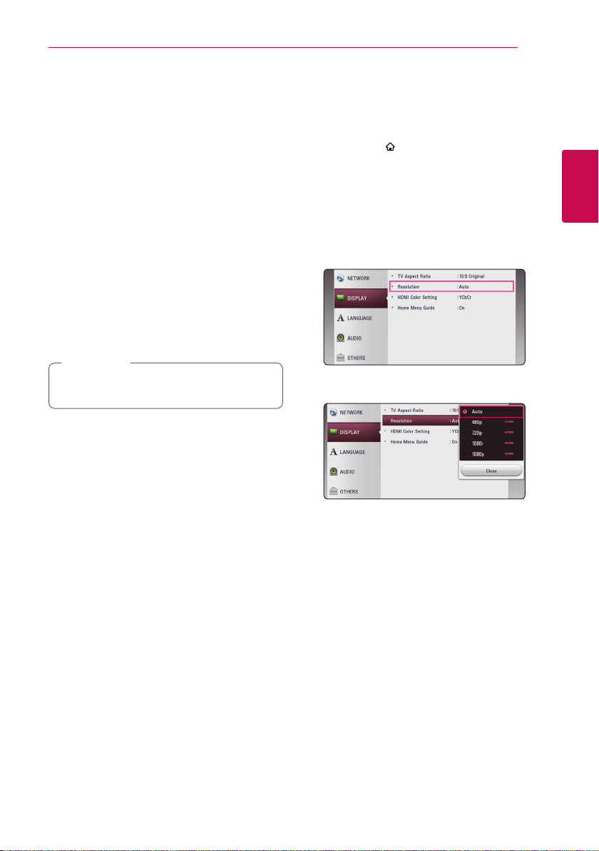
Resolution Setting
The unit provides several output resolutions for
HDMI OUT jack. You can change the resolution
using [Settings] menu.
1. Press HOME ( ).
2. Use
ENTER (b). The [Settings] menu appears.
3. Use
press D to move to the second level.
4. Use
then press ENTER (b) to move to the third
level.
5. Use
press ENTER (b) to confirm your selection.
to select the [Settings] and press
A/D
to select [DISPLAY] option then
W/S
to select the [Resolution] option
W/S
to select the desired resolution then
W/S
2
Connecting
2
Connecting
Connecting16
Note
,
yIf your TV does not accept the resolution
you have set on the unit, you can set
resolution to 480p as follows:
1. Press HOME (
menu.
2 Press Z (Stop) for more than 5 seconds.
yIf you select a resolution manually and then
connect the HDMI jack to TV and your TV
does not accept it, the resolution setting is
set to [Auto].
yIf you select a resolution that your TV
does not accept, the warning message
will appear. After resolution change,
if you cannot see the screen, please
wait 20 seconds and the resolution will
automatically revert back to the previous
resolution.
) to disappear the HOME
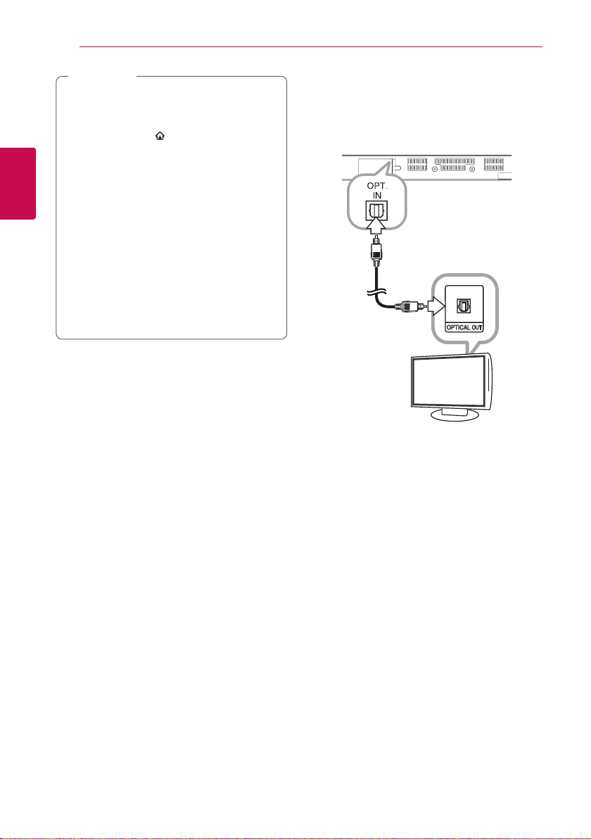
Optical digital audio connection
You can enjoy the sound from your TV with a
optical digital audio connection.
Optical digital cable
TV
Connect the optical output jack of your TV into
the OPT. IN jack on the unit. And then select the
[OPTICAL] option by pressing FUNCTION (P). Or
press OPTICAL/TV SOUND to select directly.
Connecting 17
Connections with external device
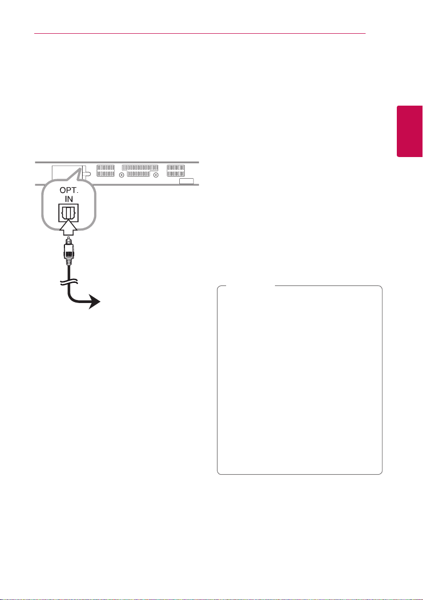
OPTICAL IN connection
You can enjoy the sound from your component
with a digital optical connection through the
speakers of this system.
To the digital
optical output jack
of your component
Connect the optical output jack of your component
into the OPT. IN jack on the unit. And then select
the [OPTICAL] option by pressing FUNCTION (P).
Or press OPTICAL/TV SOUND to select directly.
You can also use the F (Function) button on the
front panel to select the input mode.
Connecting to your Home Network
This unit can be connected to a local area network
(LAN) via the LAN port on the rear panel or the
internal wireless module.
By connecting the unit to a broadband home
network, you have access to services such as
software updates and online content services.
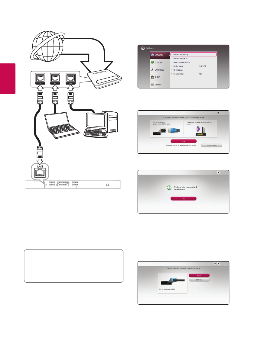
Wired network connection
Using a wired network provides the best
performance, because the attached devices
connect directly to the network and are not subject
to radio frequency interference.
Please refer to the documentation for your network
device for further instructions.
Connect the unit’s LAN port to the corresponding
port on your Modem or Router using a
commercially available LAN or Ethernet cable.
Note
,
yWhen plugging or unplugging the LAN
cable, hold the plug portion of the cable.
When unplugging, do not pull on the LAN
cable but unplug while pressing down on
the lock.
yDo not connect a modular phone cable to
the LAN port.
ySince there are various connection
congurations, please follow the
specications of your telecommunication
carrier or internet service provider.
yIf you want to access content from DLNA
servers, this unit must be connected to the
same local area network through a router.
yTo set your PC as a DLNA server, install the
supplied Nero MediaHome 4 on your PC.
(page 34)
2
Connecting
Connecting18
1. Select [Connection Setting] option in the
Broadband
service
[Settings] menu then press ENTER (b).
2
Connecting
DLNA certied servers
Wired network setup
If there is a DHCP server on the local area
network (LAN) via wired connection, this unit will
automatically be allocated an IP address. After
making the physical connection, a small number
of home networks may require the unit’s network
setting to be adjusted. Adjust the [NETWORK]
setting as follow.
Preparation
Before setting the wired network, you need to
connect the broadband internet to your home
network.
Router
2. Read the preparations for the network settings
and then press ENTER (b) while [Start] is
highlighted.
Network will automatically be connected to the
unit.
Advanced Setting
If you want to set the network settings manually,
use
[Network Setting] menu and press ENTER (b).
1. Use
to select [Advanced Setting] on the
W/S
to select [Wired] and press ENTER
W/S
(b).
Connecting 19
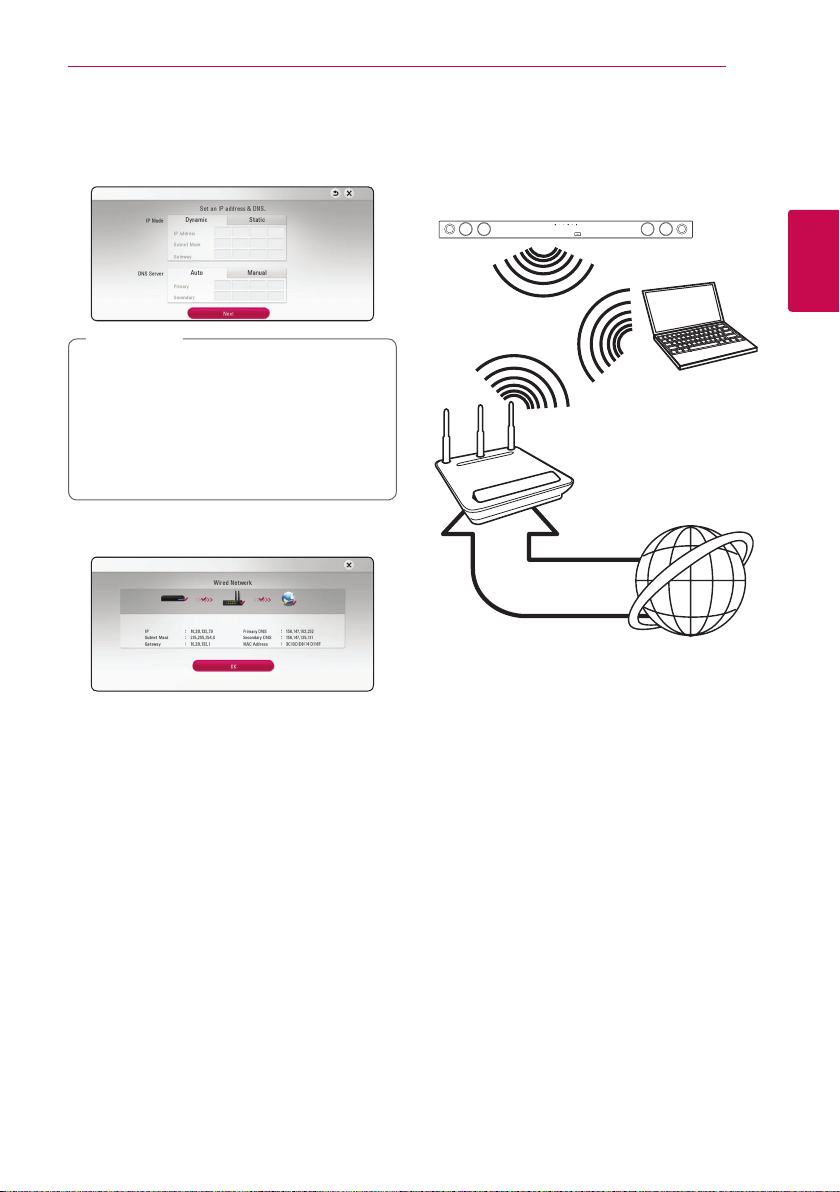
2. Use
W/S/A/D
between [Dynamic] and [Static].
Normally, select [Dynamic] to allocate an IP
address automatically.
Note
,
If there is no DHCP server on the network and
you want to set the IP address manually, select
[Static] then set [IP Address], [Subnet Mask],
[Gateway] and [DNS Server] using
and numerical buttons. If you make a
A/D
mistake while entering a number, press CLEAR
to clear the highlighted part.
3. Select [Next] and press ENTER (b) to apply
network settings.
Network connection status is displayed on the
screen.
4. Press ENTER (b) while [OK] is highlighted to
finish the wired network settings.
to select the IP mode
W/S/
Wireless network connection
Another connection option is to use an Access Point
or a wireless router. The network conguration and
connection method may vary depending on the
equipment in use and the network environment.
Wireless
Communication
DLNA certied servers
Access Point or
Wireless Router
Broadband
service
Refer to the setup instructions supplied with
your access point or wireless router for detailed
connection steps and network settings.
For best performance, a direct wired connection
from this unit to your home network’s router or
cable/DSL modem is always the best option.
If you choose to use the wireless option, please
note that performance can sometimes be aected
by other electronic devices in the home.
2
Connecting
Connecting20
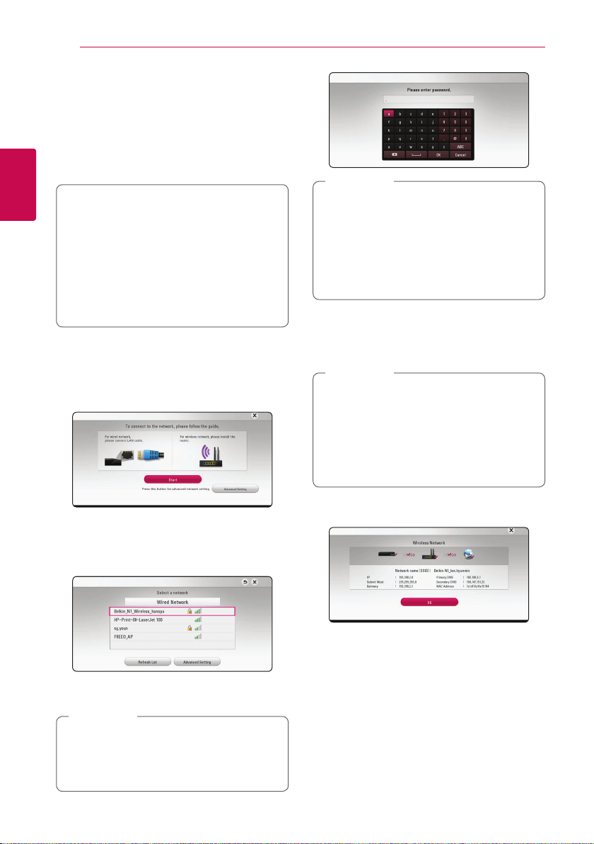
Wireless network setup
For the wireless network connection, the unit needs
to be set up for network communication. This
adjustment can be done from the [Settings] menu.
Adjust the [NETWORK] setting as follow. Setting up
the access point or the wireless router is required
before connecting the unit to the network.
2
Connecting
Preparation
Before setting the wireless network, you need
to:
-connect the broadband internet to the
wireless home network.
-set the access point or wireless router.
-note the SSID and security code of the
network.
1. Select [Connection Setting] option in the
[Settings] menu then press ENTER (b).
2. Read the preparations for the network settings
and then press ENTER (b) while [Start] is
highlighted.
Note
,
yWEP security mode generally have 4 keys
available on an access point setting. If your
access point or wireless router use WEP
security, enter the security code of the key
“No.1” to connect on your home network.
yAn Access Point is a device that allows you
to connect to your home network wirelessly.
4. Use
W/S/A/D
between [Dynamic] and [Static].
Normally, select [Dynamic] to allocate an IP
address automatically.
Note
,
If there is no DHCP server on the network and
you want to set the IP address manually, select
[Static] then set [IP Address], [Subnet Mask],
[Gateway] and [DNS Server] using
and numerical buttons. If you make a
A/D
mistake while entering a number, press CLEAR
to clear the highlighted part.
to select the IP mode
W/S/
If wired network is not connected to the unit, all
available networks are displayed on the screen.
3. Use
network and press ENTER (b).
If you have security on your access point, you
need to input the security code as necessary.
If you use other characters than the english
alphabet or digits for the SSID name of your
access point or wireless router, it may be
displayed dierently.
to select a desired SSID of wireless
W/S
Note
,
5. Select [Next] and press ENTER (b) to apply
network settings.
Network connection status is displayed on the
screen.
6. Select [OK] and press ENTER (b) to complete
the network connection.
 Loading...