

LG ARNH963K2A2, ARNH763K3B2, MULTI V ARNH963K2A2, MULTI V ARNH763K3B2 Installation Manual

Hydro Kit Medium Temperature (K2)
Hydro Kit High Temperature (K3)
Installation Manual
Hydro Kit Medium Temperature (K2)
Btu/h 107,500
Hydro Kit High Temperature (K3)
Btu/h 86,000

PROPRIETARY DATA NOTICE
This document, as well as all reports, illustrations, data, information, and
other materials are the property of LG Electronics U.S.A., Inc., and are
disclosed by LG Electronics U.S.A., Inc., only in confidence.
This document is for design purposes only.
Do not throw away, destroy, or lose this manual.
Please read carefully and store in a safe place for future reference.
Content familiarity required for proper installation.
The instructions included in this manual must be followed to prevent product malfunction, property damage, injury, or death to the user or
other people. Incorrect operation due to ignoring any instructions will cause harm or damage. The level of seriousness is classified by the
symbols described below.
This symbol indicates a potentially hazardous situation which, if not avoided, may result in death, serious injury, property
damage or equipment damage.
This symbol indicates additional helpful information such as an explanation, a comment, or a clarication about the subject.
This symbol indicates a tip or recommendation.
Recommendations instruct the user to apply the suggested practice to ensure the best operating results in order to achieve the
maximum benet of the product.
Tips contain practical information that may help the user solve a problem or describe actions that may save time.
For more technical materials such as submittals, engineering
databooks, and catalogs, visit www.lg-vrf.com.
VRF-IM-BT-001-US_014A06
For continual product development, LG Electronics U.S.A., Inc., reserves the right to change specifications without notice.
This document, as well as all reports, illustrations, data, information, and other materials are the property of LG Electronics U.S.A., Inc.
©LG Electronics U.S.A., Inc.

TABLE OF CONTENTS
SAFETY PRECAUTIONS ....................................................................... 5
Roughing-In ......................................................................................... 5
Power Wiring and Communications Cabling ....................................... 6
Installation ........................................................................................... 7
Wiring Precautions .............................................................................. 7
Operation and Maintenance ................................................................ 8
INTRODUCTION ..................................................................................... 9
Nomenclature ....................................................................................... 10
Unit Features .........................................................................................11
Parts ...................................................................................................... 13
Installation Parts ................................................................................ 13
Optional Accessories ......................................................................... 13
Specications ...................................................................................... 14
Dimensions .......................................................................................... 15
Wiring ................................................................................................... 17
ROUGHING-IN ...................................................................................... 19
Unpack the Indoor Unit / Inspect for Freight Damage ..................... 19
Receiving / Transportation / Storage ................................................. 21
General Mounting / Anchoring ........................................................... 22
Hydro Kit Wall Mounted Controller .................................................... 23
Piping .................................................................................................... 24
Refrigerant Piping ............................................................................... 26
Water Piping ......................................................................................... 27
Strainer Installation ............................................................................ 30
Accessory Installation ................................................................... 41-53
Independent Power Module (K2 Only) .............................................. 41
Hydro Kit Medium Temperature (K2) Control Panel Layout 43
Hydro Kit High Temperature (K3) Control Panel Layout .................... 43
Terminating Group Controlled Hydro Kits .......................................... 46
PRE-COMMISSIONING ........................................................................ 54
Group Control Setup ........................................................................... 54
Plan the Multi V System Central Control Addresses Assignments 54
Hydro Kit/Indoor Unit Central Control Address Assignments 54
Hex Address Assignment Limitations................................................. 54
Multi V System Central Controller Communications Limitations 54
Group Control Setup ........................................................................... 55
DIP Switch Setting - Hydro Kit Medium Temperature ...................... 56
DIP Switch Setting - Hydro Kit High Temperature ............................ 57
Installer Setting Conguration ........................................................... 58
Installer Setting Function Codes ....................................................... 59
Function Codes - Common Settings ................................................. 60
Function Codes - Hydro Kit Medium Temperature ........................... 62
Function Codes - Hydro Kit High Temperature ................................66
UNIT OPERATION ................................................................................ 70
Emergency Operation ......................................................................... 71
Maintenance ......................................................................................... 72
Seasonal (K2, K3) ................................................................................ 72
Hydro Kit Accessories ........................................................................ 73
Solar Heating System Piping .............................................................. 32
Solar Heating System Interface Kit (PHLLA) ..................................... 32
Water Piping Schematic ...................................................................... 33
Water Circuit Preparation ................................................................... 34
Power Wiring ........................................................................................ 35
Dry Contact Wiring .............................................................................. 36
Communications Cables ..................................................................... 37
LG Remote Temperature Sensor ....................................................... 40
FINISH UP ............................................................................................. 41
Troubleshooting .................................................................................. 75
Error Codes .......................................................................................... 76
Troubleshooting .................................................................................. 77
Finishing the Installation .................................................................... 79
Installation Checklist .......................................................................... 80
Device Conguration Worksheet ....................................................... 82
Who to Call for Assistance ................................................................. 83
3

MULTI V Hydro Kit Installation Manual
This page left intentionally blank.
Due to our policy of continuous product innovation, some specications may change without notication.
4
©LG Electronics U.S.A., Inc., Englewood Cliffs, NJ. All rights reserved. “LG” is a registered trademark of LG Corp.
SAFETY PRECAUTIONS
IMPORTANT!
•Please read this manual completely before installing the product.
•As an installer or service provider, it is your job to install or service the system to operate safety and efficiently. Improper installation, ad-
justment, alteration, service, or maintenance is dangerous to personnel and/or property and can void the warranty.
•Follow the instructions in this manual to prevent product malfunction, property damage, injury or death to the user or other people.
Incorrect operation due to ignoring any instructions will cause harm or damage.
•The level of seriousness is classified by the symbols described below.
This symbol indicates a potentially hazardous situation which, if not avoided, may result in death or serious injury.
This symbol indicates additional helpful information such as an explanation, a comment, or a clarication about the subject.
This symbol indicates a tip or recommendation.
Recommendations instruct the user to apply the suggested practice to ensure the best operating results in order to achieve the
maximum benet of the product.
Tips contain practical information that may help the user solve a problem or describe actions that may save time.
Safety Precautions
Roughing-In
If the air conditioner is installed in a small space, take
measures to prevent the refrigerant concentration from
exceeding safety limits in the event of a refrigerant leak.
Consult the latest edition of ASHRAE (American Society of Heating,
Refrigerating, and Air Conditioning Engineers) Standard 15. If the
refrigerant leaks and safety limits are exceeded, it may result in personal
injuries or death from oxygen depletion.
Do not install, remove, or re-install the unit by yourself
(customer).
There is risk of re, electric shock, physical injury or death.
Ask the dealer or an authorized technician to install the unit.
Improper installation by the user may result in water leaks, re, electric
shock, physical injury or death.
For re-installation, always contact the dealer or an authorized
service provider.
There is risk of re, electric shock, physical injury or death.
Be very careful when transporting the unit.
• Indoor unit weight and size preclude one person carrying the unit.
Use two or more people to transport the unit without the assistance of mechanical transport equipment because there is a risk of
personal injury.
• Some products use polypropylene bands for packaging. Do not use
polypropylene bands to lift the unit.
• Suspend the water source unit from the base at specified positions.
Support the outdoor unit a minimum of four points to avoid slippage
from rigging apparatus.
Do not handle indoor units without the use of gloves and
protective clothing. The unit may have sharp edges.
There is a risk of personal injury.
Dispose the packing materials safely.
Destroy the structure of plastic packaging and boxes to prevent children
from playing with them. There is a risk of injury, suffocation and/or death
to humans, animals and wildlife.
Do not install the unit on an unstable structure.
It may result in the failure of the structure, property damage, equipment
damage, and/or personal injury or death.
Install the unit in a safe location where nobody can step on
or fall onto it.
There is risk of unit damage, physical injury or death.
R410A and R134a refrigerants create toxic gases when
burned. Do not store or use ammable products near the
unit.
There is risk of product failure, re, and physical injury or death.
Replace all control box and panel covers after completing
work.
Failure to do so may result in dust or water inltration, causing re, electric
shock, and physical injury or death.
Always wear safety glasses and work gloves when installing
the unit. A rapid release of R410A and R134a refrigerants may
cause frostbite.
Due to our policy of continuous product innovation, some specications may change without notication.
©LG Electronics U.S.A., Inc., Englewood Cliffs, NJ. All rights reserved. “LG” is a registered trademark of LG Corp.
5
SAFETY PRECAUTIONS
Roughing-In — Continued
Properly insulate all cold surfaces when installing this product.
Uninsulated cold surfaces may generate condensate that may drip and
cause water damage to wall and oors.
air conditioner to malfunction.
Install the unit considering the potential for earthquakes.
Improper installation may cause the unit to fall over, resulting in physical
injury or death.
This product is engineered to be used for comfort cooling /
heating. It is not to be used in applications that require
precision cooling or heating such as data centers, food
preservation, wine coolers, refrigeration and / or freezer
applications.
There is risk of property damage.
Provide eld-installed electrical isolation devices to protect
sensitive equipment sharing a power source with this product.
Provide sufcient protection against the effects of
electromagnetic elds (EMF) and electrical noise.
Inverter equipment, private power generators, high-frequency
medical equipment, or radio communication equipment may cause the
Power Wiring and Communications Cabling
The information contained in this manual is intended for use
by a qualied, experienced service technician who is familiar
with safety procedures and equipped with the proper tools
and test instruments.
Failure to carefully read and follow all instructions in this manual
may result in equipment malfunction, property damage, personal injury
or death.
Always use lock-out, tag-out procedures!
Ensure the electrical power is off and the disconnect is locked and tagged
prior to working on the Hydro Kit.
MULTI V Hydro Kit Installation Manual
All electric work must be performed by a licensed electrician
and conform to local building codes or, in the absence of local codes, with the National Electrical Code, and the instructions given in this manual.
If the power source capacity is inadequate or the electric work is not
performed properly, it may result in re, electric shock, physical injury or
death.
This equipment uses high voltage electricity. Only a qualied,
experienced electrician should wire this system. Never
assume that the electrical power has been disconnected.
Verify with a meter.
Failure to properly respect electricity, use industry best grounding practices, follow suggested wiring instructions, local, and NEC codes can lead
to electrical shock, physical injury, seizures, and death.
Do not install this product in a location that is noise
sensitive. Provide additional acoustical treatment as needed.
The risk is occupants may be discomforted.
Provide sufcient electrical system protection against
lighting strikes.
The risk is loss of warranty, product damage, and / or complete loss of
this product.
When installing refrigerant piping, consider pipe expansion.
Improper pipe installation may lead to pipe fatigue, failure, and a rapid
release of refrigerant, frostbite, suffocation, physical injury, and or death.
Use a properly sized circuit protective device. Using an undersized protective device will lead to equipment malfunction. In-
stalling an oversized protective device may cause burns, re,
and death.
There is risk of re, electric shock, explosion, physical injury or death.
Always ground the unit following local, state, and NEC codes.
There is risk of re, electric shock, and physical injury or death.
Do not use a eld-provided communications cable between
the Hydro Kit and the Hydro Kit Wall Mounted Controller. Use
only LG provided communications cable. Do not shorten,
modify, lengthen, or remove factory plug-able connectors
from the communications cable provided with the Hydro Kit
Wall Mounted Controller wiring kit.
Verify all power, ground, and communications wires and
cables are properly terminated before applying power to the
product. Securely tighten all wire terminations.
The product will malfunction.
Improper and/or loose wire and communications cable terminations may
cause product malfunction, re, physical injury or death.
Properly secure power wires and communications cables
at connectors, and provide slack in cable to eliminate wire
strain.
Inadequate connections may generate heat or cause a re and result in
physical injury or death.
Refer to local, state, and federal codes, and use power wires
of sufcient current capacity and rating.
Wires that are too small may generate heat and cause a re.
Due to our policy of continuous product innovation, some specications may change without notication.
6
©LG Electronics U.S.A., Inc., Englewood Cliffs, NJ. All rights reserved. “LG” is a registered trademark of LG Corp.
Turn power off at the unit disconnect before servicing.
Electrical shock can cause physical injury or death.
Installation
SAFETY PRECAUTIONS
Always use lock-out, tag-out procedures!
Ensure the electrical power is off and the disconnect is locked and tagged
prior to working on the Hydro Kit.
Verify the piping system has been properly evacuated
(<500 ppm), and the system’s refrigerant charge is correct
before commissioning and after any repair is made.
Improper system evacuated and/or an improper refrigerant charge may
cause product malfunction.
Do not install the units outside.
There is risk of re, electric shock, explosion, and physical injury or death.
Do not change the settings of the protection devices.
If the pressure switch, thermal switch, or other protection device is
shorted and forced to operate improperly, or parts other than those
specied by LG are used, there is risk of re, electric shock, explosion,
and physical injury or death.
Do not store or use ammable gas or combustibles near the
unit.
There is risk of product failure, re, explosion, and physical injury or death.
Replace all control box and panel covers.
If cover panels are not installed securely, dust, water and animals may
enter the outdoor unit, causing re, electric shock, and physical injury or
death.
Hydro Kit High Temperature Water Heater (K3) must be kept
in an upright position during installation.
To avoid oil migration from the onboard compressor..
Do not make refrigerant substitutions. Use the refrigerant
listed on the nameplate of the unit.
If a different refrigerant is used, or air mixes with original refrigerant, the
unit will malfunction and be damaged.
Take appropriate actions at the end of HVAC equipment life
to recover, recycle, reclaim or destroy refrigerants
according to applicable U.S. Environmental Protection
Agency (EPA) rules.
Wiring Precautions
Turn the power off at the nearest disconnect before servicing
the equipment.
Electrical shock can cause physical injury or death.
Do not supply power to the unit until all electrical wiring,
controls wiring, piping, installation, and refrigerant system
evacuation are completed AND the commissioning agent has
authorized you to do so.
Safety Precautions
Always check for system refrigerant leaks after the unit has
been installed or serviced.
Low refrigerant levels may cause product failure, and exposure to high
concentration levels of refrigerant gas may lead to illness or death.
Due to our policy of continuous product innovation, some specications may change without notication.
©LG Electronics U.S.A., Inc., Englewood Cliffs, NJ. All rights reserved. “LG” is a registered trademark of LG Corp.
7

SAFETY PRECAUTIONS
Operation and Maintenance
Do not allow water, dirt, or animals to enter the (Hydro Kit)
unit.
There is risk of unit failure, re, electric shock, physical injury or death.
Do not provide power to or operate the unit if it is ooded or
submerged.
There is risk of re, electric shock, physical injury or death.
Do not operate the disconnect switch with wet hands.
There is risk of re, electric shock, physical injury or death.
Periodically verify the equipment mounts have not
deteriorated.
If the base collapses, the unit could fall and cause property damage, product failure, physical injury or death.
Do not touch the refrigerant piping during or after operation.
It can cause burns or frostbite.
Do not operate the unit with the panel(s) or protective
cover(s) removed; keep ngers and clothing away from
moving parts.
The rotating, hot, cold, and high-voltage parts of the unit can cause physical injury or death.
If a refrigerant gas leak is detected, leave the room!
Refrigerant gas in sufcient quantity in an enclosed area can cause suffocation and death. Obtain a properly maintained Self Contained Breathing Apparatus (SCBA) and training on how to use it before reentering the
area
For the High Temperature Heating Model (K3), turn on the
power at least six (6) hours before operation begins.
Starting operation immediately after turning on the main power switch can
result in severe damage to the compressor(s). Keep the power switch on
during the operational season.
Clean up the site after servicing is nished, and check that
no metal scraps, screws, or bits of wiring have been left
inside or surrounding the Hydro Kit.
MULTI V Hydro Kit Installation Manual
Due to our policy of continuous product innovation, some specications may change without notication.
8
©LG Electronics U.S.A., Inc., Englewood Cliffs, NJ. All rights reserved. “LG” is a registered trademark of LG Corp.
INTRODUCTION
Hydro Kit Models
This manual describes how to install the Multi V™ Hydro Kit. The Hydro Kit is available in two models. Refer to Table 1 for model chassis,
model number and capacities.
Table 1: Hydro Kit Model Numbers and Capacities
Unit Chassis Name Model Number Capacity
Hydro Kit Medium Temperature K2 ARNH963K2A2
Hydro Kit High Temperature K3 ARNH763K3B2 Heating Only: 86,000 Btu/h
These units are to be used in conjunction with LG’s Multi V Variable Refrigerant Flow (VRF) Heating, and Air Conditioning system. Both units
operate on 208–230 V, 60 Hz, 1-phase power.
Install these unit(s) in the location(s) specied by your design engineer, HVAC system layout drawings and project specications. Perform the installation according to the procedures in this manual. Improper installation may result in injury to or death of personnel, equipment malfunction and/or
property damage.
Cooling: 95,900 Btu/h
Heating: 107,500 Btu/h
Introduction
More in-depth technical and performance information on these units is available in the Multi V™ Hydro Kit Engineering Manual available at
http://www.lg-vrf.com.
HydroKit Medium Temperature (K2)
HydroKit High Temperature (K3)
Due to our policy of continuous product innovation, some specications may change without notication.
©LG Electronics U.S.A., Inc., Englewood Cliffs, NJ. All rights reserved. “LG” is a registered trademark of LG Corp.
9
NOMENCLATURE
HydroKit Nomenclature
ARN H 96 3 K2 A
Family
ARN = Multi V Indoor Unit
(Refrigerant R410A)
Type
H = Hydro Kit
Nominal Capacity
(Total Heating Capacity in Btu/h)
96 = 107,500
76 = 86,000
Electrical Ratings
3 = 208–230V/60Hz/1Ph
Chassis
K2 = Hydro Kit Medium Temperature
K3 = Hydro Kit High Temperature
2
Combination of functions
A = Standard
MULTI V Hydro Kit Installation Manual
B = High Temperature Water Heater
Generation
2 = Second
Due to our policy of continuous product innovation, some specications may change without notication.
10
©LG Electronics U.S.A., Inc., Englewood Cliffs, NJ. All rights reserved. “LG” is a registered trademark of LG Corp.
UNIT FEATURES
Table 2 compares main features of the two Hydro Kit models.
Hydro Kit Compatibility
The Hydro Kit is fully compatible with Multi V III, Multi V IV and Multi V Water IV units. The Hydro Kit is not compatible with Multi V Mini, Multi
V Plus II, Multi V Sync II, Multi V Space, Multi V Water II, Multi V Water Mini or any duct-free split products.
Table 2: Hydro Kit Product Features.
Features ARNH963K2A2 ARNH763K3B2
Self diagnosis
Auto Start
*Manual or Auto Restart
Child Lock
Group Control
Timer (on/off)
Controller Based Functions
Timer (weekly)
1
2
2
Hydro Kit Wall Mounted
Controller
Network Solution (LGAP)
Remote Enable/Disable via
LG Dry Contact
BMS Integration
Power Distribution
3
Indicator (PDI) Interface
Remote Temperature
Sensor
Solar Heating Circuit
Options
Interface
1
Hydro Kit models (i.e., K2 and K3 chassis) cannot be mixed within the same group. Each Hydro Kit unit group must be connected to the same outdoor unit.
1
√ √
√ √
√ √
√ √
√ √
X √
X √
√ √
√ √
PQDSB-1 PQDSB-1
X √
PQRSTA0 PQRSTA0
PHLLA X
Hydro Kit Based Functions
Features ARNH963K2A2 ARNH763K3B2
Hydronic Circuit Isolation
Water Pump ON/ OFF
Control
Factory Mounted Flow
Switch
√ X
√ √
√ √
Conventional line voltage
(208-230° v) Thermostat
√ √
Interface2
Conventional 24 vac
Thermostat Interface2
Conventional Mechanical
Thermostat Interface
1
Indirect Tank Water
Pre-Heating
3rd Party Solar Heating
System Flow Control
Storage Tank Heating
Operation Timer
Water Temperature Reset
Overheating Protection
Emergency Heating
Operation
√ X
√ √
√ √
√ X
√ √
√ √
√ √
√ √
Hydro Kit units within the same group must have the same DIP switch settings. The only DIP switch that can differ is the group control setting switch, where
one Hydro Kit will be the master and the remaining Hydro Kit units will be slaves.
2
Manual restart is not available when the Hydro Kit is configured for conditioned space control, using a conventional thermostat.
3
Sold separately and field installed.
KEY:
Introduction
√:Available
X: Not available
Due to our policy of continuous product innovation, some specications may change without notication.
©LG Electronics U.S.A., Inc., Englewood Cliffs, NJ. All rights reserved. “LG” is a registered trademark of LG Corp.
11
UNIT PIPE, WIRE AND CABLE
CONNECTION
The following diagrams display all piping and cable routing locations on the two chassis.
Hydro Kit Medium Temperature — K2
Power Wire Knock-out
Communication Cable Knock-out
Hydronic Circuit Water Outlet Connection
R-410a Low Pressure Vapor Pipe Connection
R-410a High Pressure Vapor
Liquid Pipe Connection
Condensate Drain Pipe
Hydronic Circuit Water Inlet Connection
Figure 1: Medium Temperature (K2) Unit Connections
Hydro Kit High Temperature — K3
MULTI V Hydro Kit Installation Manual
Heating Circuit Water Outlet Connection
Communication Cable Knock-out
Power Wire Knock-out
R-410a Low Pressure Vapor Pipe
R-410a High Pressure Liquid Pipe
Heating Circuit Water Inlet Connection
Figure 2: High Temperature (K3) Unit Connections
Due to our policy of continuous product innovation, some specications may change without notication.
12
©LG Electronics U.S.A., Inc., Englewood Cliffs, NJ. All rights reserved. “LG” is a registered trademark of LG Corp.
PARTS
Installation Parts
Table 3 lists installation parts for the K2 and K3 models of the Hydro Kit. Be sure all field-provided parts meet appropriate local and national
codes. Quantities are per each unit installed.
Table 3: Parts and Accessories Provided for each Hydro Kit
Part Quantity Part Image
Installation Manual (this manual) 1 n/a
Hydro Kit Remote Control Panel 1
Sensor Well 1
Indirect Hot Water Storage Tank
Sensor
Refrigerant Strainer 1
Independent Power Module 1
1
Optional Accessories
Table 4 lists additional optional accessories available through LG Electronics.
Table 4: Optional Accessories Available from LG Electronics
Part Model Description
Remote Wall Mounted Sensor PQRSTA0
Control via the Hydro Kit based on
conditioned space temperature.
Introduction
Dry Contact PQDSB-1 Binary closure- Remote Enable/Disable.
Solar Heating System
Interface Kit
PHLLA Solar heating system interface.
Due to our policy of continuous product innovation, some specications may change without notication.
©LG Electronics U.S.A., Inc., Englewood Cliffs, NJ. All rights reserved. “LG” is a registered trademark of LG Corp.
13

SPECIFICATIONS
Table 5 lists specifications for each Hydro Kit chassis (K2 and K3). Note that due to the functionality of each Hydro Kit some types of specs
will not be available on certain unit models.
Table 5: HydroKitSpecications
Type ARNH963K2A2 ARNH763K3B2
Power Supply (V/Hz/Ph) 208-230/60/1 208-230/60/1
Rated Cooling Capacity (Btu/h) 95,900 n/a
Rated Heating Capacity (Btu/h) 107,500 86,000
Nominal Dimensions W x D x H (In) 21 x 25 x 13 21 x 43 x 13
Net Weight (lbs) 78 208
Shipping Weight (lbs) 89 219
Type
Refrigerant
to Water Heat Exhanger
Water Pipe Connections
Refrigerant Pipe
Connections
Drain Connection 1” MPT 1” MPT
Multi V ODU Comm. Cable
(AWG -# Conductors, type)
Hydro Kit Wall Mounted Controller
Communication Cable
Internal Circuit
MULTI V Hydro Kit Installation Manual
Rated Water
Flow (GPM)
Pressure Drop (ft-wg) 23.1 7
Inlet Diameter 1” MPT 1” MPT
Outlet Diameter 1” MPT 1” MPT
Liquid ODU (in) 3/8 3/8
Vapor Gas ODU (in) 7/8 3/4
Refrigerant Type - R410A
Control Device - Electronic Expansion Valve
Brazed Plate Heat
Exchanger
24.3 9.5
18-2 stranded shielded 18-2 stranded shielded
Use LG supplied cable only Use LG supplied cable only
Brazed Plate Heat
Exchanger
Refrigerant Type R410A R134a
Multi V System
14
Refrigerant
Charge (lbs)
Control Device Electronic Expansion Valve Electronic Expansion Valve
Due to our policy of continuous product innovation, some specications may change without notication.
©LG Electronics U.S.A., Inc., Englewood Cliffs, NJ. All rights reserved. “LG” is a registered trademark of LG Corp.
- 6.6
DIMENSIONS
Hydro Kit - K2
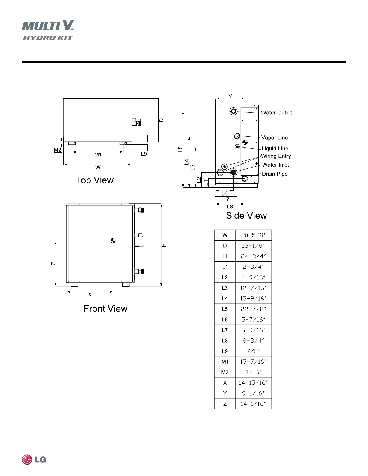
Figure 3 shows the dimensional diagram of the Hydro Kit Medium Temperature, along with piping and cabling information.
Introduction
Due to our policy of continuous product innovation, some specications may change without notication.
©LG Electronics U.S.A., Inc., Englewood Cliffs, NJ. All rights reserved. “LG” is a registered trademark of LG Corp.
Figure 3: Dimensions for Hydro Kit — K2
15
DIMENSIONS
Hydro Kit - K3
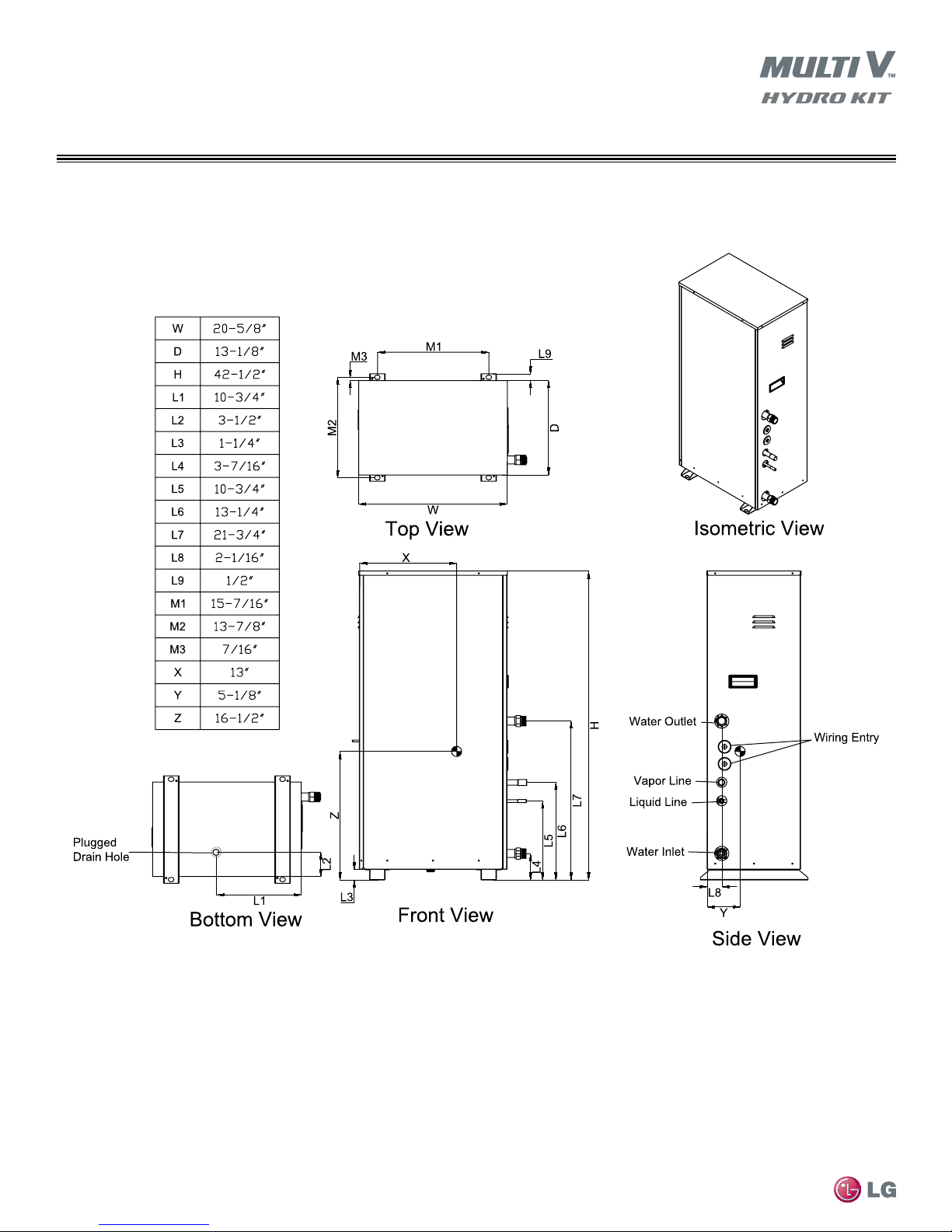
Figure 4 shows the dimensional diagram of the Hydro Kit High Temperature, along with piping and cabling information.
MULTI V Hydro Kit Installation Manual
Due to our policy of continuous product innovation, some specications may change without notication.
16
©LG Electronics U.S.A., Inc., Englewood Cliffs, NJ. All rights reserved. “LG” is a registered trademark of LG Corp.
Figure 4: Dimensions for Hydro Kit (K3)
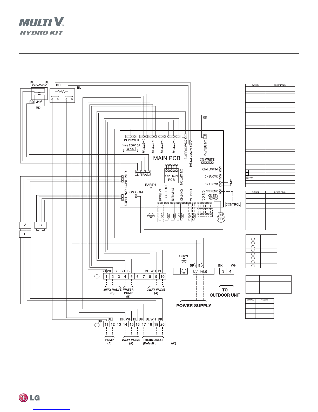
Figure 5 shows the wiring diagram for the Hydro Kit Medium Temperature.
(USE COPPER WIRE ONLY)
208-230V/60/1
208/230V
24V Transformer
Water Pump
Pilot Relay
A
B
*For 24V thermostat disconnect housting A and C then connect housing B and C
*
**
F
Sockets and Connections+
Wi
WH White
WIRING
Hydro Kit - K2
CN-2WAY (A)
CN-2WAY (B)
CN-3WAY (A)
CN-3WAY (B)
CN-CC
CN-COM
CN-EEV
CN-FLOW1
CN-FLOW2
CN-FLOW3-4
CN-OPTION
CN-PIPEIN
CN-PIPEOUT
CN-POWER
CN-REMO
CN-ROOM
CN-TH3(TOP/LEFT)
CN-TH3(BOTTOM/
CENTER)
CN-TH4(TOP)
CN-TH4(BOTTOM)
CN-THM01
CN-THM02
CN-TRANS
CN-W/PUMP (A)
CN-W/PUMP (B)
CN-WRITE
EARTH
L
N
To terminal strip B, screws 14, 15, 16
Not used
To terminal strip A, screws 8, 9, 10
To terminal strip A, screws 1, 2, 3
Optional LG Dry Contact connection
Multi V communication to outdoor or water
source unit
R410A EEV value
Factory mounted ow switch
Not used
Not used
Option card interface
Heat exchanger - refrigerant pipe in
temperature
Heat exchanger - refrigerant pipe out
temperature
AC power to PCB
Hydro Kit unit controller
LG Remote Temperature Sensor (optional)
Heat exchanger-inlet water temperature
sensor
Heat exchanger-outlet water temperature
sensor
Temperature sensor: Solar heating circuit
temperature sensor (optional)
Temperature sensor: Hot water storage tank
sensor (eld mounted)
3rd Party 208-230/60/1 thermostat (option)
3rd Party 24VAC thermostat (option)
24 Volt power to PCB
To terminal strip B, screws 11, 12: Solar
heating system circulating pump
To terminal strip A, screws 4,5: Solar heating
system circulating pump
Not used
Earth Ground
Line (+) power connection 208-230/60/1
Neutral (-) power connection 208-230/60/1
Ground
Thermistor
Fuse
ield Connections - LG Sourced Accessories
CN-ROOM
CN-REMO
CN-CC
CN-TH4 (TOP)
CN-TH4 (BOTTOM)
CN-EEV
CN-WRITE
CN-EEV/LOAD
Field Supplied Connections
TERMINAL STRIP SCREW TERMINALS
NOTE: If a 24 volt thermostat will be used, adjust wiring
harness conguration
Wire Harness A
Wire Harness B
Wire Harness C
LG remote temperature sensor (optional)
Remote mounted Hydro Kit unit controller
LG Dry Contact PCB interface (3rd party
binary signal enabe/disable
LG Solar Kit temperature sensor for
secondary heated water storage tank
LG provided hot water tank temperature
sensor
5-wire harness from power module accessory
CN-EEV/MAIN to CN-EEV on the Hydro Kit
MAIN PCB
Single wire from power module accessory
CN-EEV/MAIN to Hydro Kit MAIN PCB
CN-WRITE
Wire harness from power module accessory
to Hydro Kit EEV valve
A
1, 2, 3
A
4,5
A
6,7
A
8, 9, 10
B
11, 12
B
13
B
14, 15, 16
B
17, 18, 19, 20
PCB interface 208-230/60/1 or
mechanical conventional thermostat
PCB interface for 24VAC conventional
thermostat
Wire harness Plug C to conventional
thermostat terminals 18, 19, 20
re Color Legend
Black
BK
Blue
BL
BrownBR
GR Green
RD Red
Yellow
YL
Introduction
Due to our policy of continuous product innovation, some specications may change without notication.
©LG Electronics U.S.A., Inc., Englewood Cliffs, NJ. All rights reserved. “LG” is a registered trademark of LG Corp.
Figure 5: Wiring for Hydro Kit (K2 Chassis)
17
WIRING
(USE COPPER WIRE ONLY)
208-230/60/1
208/230V
R-134A Inverter
Compressor
RS 485
Communication Board
Crankcase
Heater
Inverter PCB
Cooling Fan
MAIN PCB
Field Connections - LG Sourced Accessories
Sockets and Connections - Main PCB
CN-3WAY (A)
CN-CC
CN-COM
CN-CC
CN-COM
CN-EEV
CN-FLOW1
To terminal strip A, screws 4,5,6
Optional LG Dry Contact connection
Multi V communication to outdoor or water
source unit
Optional LG Dry Contact connection
Multi V communication to outdoor or water
source unit
R410A EEV value
Factory mounted ow switch
CN-FLOW3-4
Power to RS-484 communications PCB
CN-OPTION
Option card interface
CN-PIPEIN
Heat exchanger - refrigerant pipe in
temperature
CN-PIPEOUT
Heat exchanger - refrigerant pipe out
temperature
CN-POWER
AC power to PCB
CN-REMO
Hydro Kit unit controller
CN-ROOM
LG Remote Temperature Sensor (optional)
CN-TH3(TOP/LEFT)
Heat exchanger-inlet water temperature
sensor
CN-TH3(BOTTOM/
CENTER)
Heat exchanger-outlet water temperature
sensor
CN-TH4(TOP)
Not used
CN-TH4(BOTTOM)
Hot water storage tank sensor (eld
mounted)
CN-THM01
To terminal strip A, screws 7,8,9,10
CN-WRITE
EARTH
Earth Ground
CN-DC
Communications link with inverter board
TERMINAL STRIP SCREW TERMINALS
A
A
A
A
1, 2
3
4,5,6
7,8, 9, 10
Field Supplied Connections
Wire Color Legend
BK
Black
BL
Blue
BrownBR
GR Green
RD Red
YL
Yellow
WH White
Not used
Sockets and Connections - Inverter and Other PCB’s
CN-COOLING
CN-Heater1
CN-N/F
AC (N)
AC (L)
W, U, V
CN-EEV1
Inverter PCB cooling fan
R134A compressor crankcase heater
Filtered power to inverter
Line power neutral
Line power 208-230/60/1
Inverter compressor connection
R134A circuit EEV
CN-485/DRY
Communications link
P-SENSOR (L)
Power to noise lter
P-SENSOR (H)
R134A high pressure sensor
CN-TH3
R134A compressor discharge pipe
thermistor
CN-TH2
R134A compressor suction pipe thermistor
CN-INVERTER
R134A low pressure sensor
Ground
Thermistor
Fuse
CN-ROOM
CN-REMO
CN-CC
CN-TH4 (BOTTOM)
LG remote temperature sensor (optional)
Remote mounted Hydro Kit Unit Controller
LG Dry Contact PCB interface (3rd party
binary signal enable/disable
Temperature sensor: Hot water storage tank
sensor (eld mounted)
A
Hydro Kit - K3
Figure 6 shows the wiring diagram for the High Temperature Heating Hydro Kit.
MULTI V Hydro Kit Installation Manual
Due to our policy of continuous product innovation, some specications may change without notication.
18
©LG Electronics U.S.A., Inc., Englewood Cliffs, NJ. All rights reserved. “LG” is a registered trademark of LG Corp.
Figure 6: Wiring for Hydro Kit (K3 Chassis)
ROUGHING-IN
Unpack the Indoor Unit / Inspect for Freight Damage
Choose a location in the vicinity of the installation before removing the protective materials.
After opening, if the unit is damaged, repack the unit as it was shipped to you. RETAIN ALL PACKING MATERIALS. In general, freight damage claims
will be denied if the original packing materials are not retained for the claims adjustor to inspect. Call your supervisor on how to proceed with ling a
freight claim and to order a replacement unit.
1. Before opening, check the unit model number on the box. Verify it is the correct capacity, unit type and voltage. Refer to Nomenclature
Chart on page 10 of this manual.
2. Place the box on a solid surface right side up.
3. Cut the white reinforced nylon straps.
4. Open the top of the box and fold back all four flaps.
5. Remove the protective cardboard.
6. The walls and top panels are not attached to the bottom of the box. Lift the cardboard carton by the flaps and remove the box walls and
top and place it to the side.
7. Remove the moisture barrier plastic bonnet.
8. Check the unit nameplate data and model number. Verify the unit voltage, and capacities are correct before proceeding.
9. Remove and retain the installation manual. It is located under the unit, on top of the unit, or taped and inserted inside the unit cabinet.
10. Lift the unit (but not by refrigerant piping!) and inspect for freight damage. If damage is found, repack the unit as it was received in the
original container.
Installation
DO NOT lift the unit by the refrigerant piping. Use the hanger brackets or the unit case only to lift the unit. Damage to the piping components may occur.
Location Selection
Select a location for installing the unit where:
•The location is indoors in a conditioned space and protected from outdoor weather events.
•The mounting structure will support the weight of the unit(s), piping, and accessories.
•The unit is level.
•Space is allocated for heat exchanger maintenance and draining.
•Space is allocated for the connection of necessary piping.
•Proper electrical panel clearance requirements are satisfied.
•The unit is not exposed to steam, humid air, caustic, and/or acidic
chemical vapors such as but not limited to Chlorine or Muratic acid.
•Provide minimum maintenance clearance and electrical component service areas as shown in Figure 7
•Refer to Table 6 for clearance measurements specific to each chassis.
Due to our policy of continuous product innovation, some specifications may change without notification.
©LG Electronics U.S.A., Inc., Englewood Cliffs, NJ. All rights reserved. “LG Life’s Good” is a registered trademark of LG Corp.
19
Match Letter
Clearance Area to
Corresponding
Hydro Kit Chassis
K3 Chassis
ROUGHING-IN
Roughing-In the Hydro Kit Chassis
Figure 7: Minimum Clearance Areas Around Units
K2 Chassis
Match Letter
Clearance Area
to Corresponding
Hydro Kit Chassis
MULTI V Hydro Kit Installation Manual
Table 6: Hydro Kit Minimum Clearance Dimension in Inches
Hydro Kit
Chassis
K2 20-1/2 24 --- --- --- --- 13-1/2 8 25
K3 20-1/2 24 42-1/2 13-1/2 3-1/2 10-1/2 32 13-1/2 14 27
20
Maintenance Ventilation Piping / Heat Exchanger Pull
A B C E F G H I J K
Due to our policy of continuous product innovation, some specifications may change without notification.
©LG Electronics U.S.A., Inc., Englewood Cliffs, NJ. All rights reserved. “LG Life’s Good” is a registered trademark of LG Corp.
ROUGHING-IN
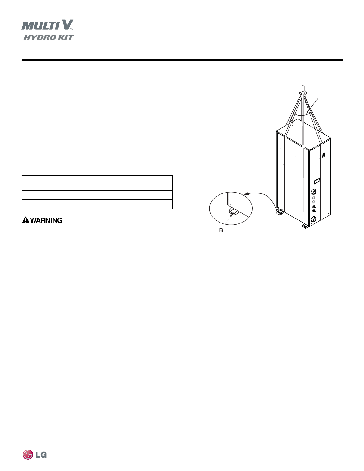
Receiving / Transportation / Storage
Transporting / Lifting
Figure 8: Proper Transportation of Unit
•Refer to Table 7 for accurate weights before transporting or lifting.
•When lifting the unit, use the lifting straps and place around the unit.
A
•Always lift the unit using properly sized lifting straps rated to carry the
unit weight.
•Ensure the straps are long enough to maintain a maximum of a 40°
angle as shown at “A” in Figure 8.
A
•Center of gravity information regarding each Hydro Kit unit can be
found on the dimensional drawings for the specific unit, on Figure 3
and Figure 4 of this installation manual.
A:
≤40°
B:
Mounting Rail
Table 7: Hydro Kit Chassis Net and Shipping Weights
Chassis Net Weight (lbs.) Shipping Weight
(lbs.)
ARNH963K2A2 78 89
ARNH763K3B2 208 219
• One person should not carry the product.
• Some products include polypropylene bands around the unit for packag-
ing. Do not use polypropylene bands to lift the unit.
• Tear apart and throw away plastic packaging bags so that children may not play with them and risk suffocation and death.
• Lift the water source unit from the base at specified locations. Support the water source unit at a minimum of six (6) points to avoid slip-
page from the rigging apparatus.
• Do not drop the unit when carrying it with a forklift.
• Use a minimum of three (3) lifting straps.
• Place a protective cloth or other soft material at the locations where the casing comes in contact with the lifting straps to prevent damage
to painted surfaces.
• Always know where the center of gravity of the water source unit is before lifting. Hoist the unit with the center of gravity centered among
the lifting straps.
• Use caution when using forklift to transport an unpackaged unit. Consider the unit’s center of gravity when lifting. Protect the painted
surfaces as necessary to prevent damage to the unit finish.
Installation
Due to our policy of continuous product innovation, some specifications may change without notification.
©LG Electronics U.S.A., Inc., Englewood Cliffs, NJ. All rights reserved. “LG Life’s Good” is a registered trademark of LG Corp.
21

ROUGHING-IN
General Mounting / Anchoring
General Mounting
Securely attach the Hydro Kit to a concrete pad, base rails, or other mounting platform anchored to the building structure.
Avoid placing the unit in a low lying area where water may accumulate. Refer to dimensional drawing on page 15 and on page 16 of this
manual, and follow the applicable local code for clearance, mounting, anchor, and vibration attenuation requirements.
Place rubber isolation pads between the mounting feet and the base. Secure the feet to the base using washers and nuts. Fix the unit tightly
with bolts as shown below in Figure 9.
• When building a base support for the Hydro Kit, ensure that the floor surface / location has enough strength to support the weight of the unit,
enough space for pipes and wiring, the condensate drain connection, and the floor drain.
• Install the Hydro Kit to a base and in a manner approved by the structural engineer to minimize damage to the unit in the event of an earth-
quake. Any deficiency in installation may cause unit to fall, resulting in physical injury or death.
Anchoring the Hydro Kit Unit
Figure 9 shows the proper location and mounting of the anchor bolts for the Hydro Kit.
Figure 9: Location of the Anchor Bolts
15-1/4
Front
MULTI V Hydro Kit Installation Manual
Plan View
Guidelines
• Securely fasten all four (4) corners to the supporting base.
• If not otherwise directed by the structural engineer or local codes,
Use a 7/16 inch or 1/2 inch diameter J-bolt. Use a hexagon nut with
a spring washer.
• Include anti-vibration material chosen by the acoustics engineer.
• Include enough space for refrigerant piping and electrical wiring
when installing through the bottom of the unit.
• Use an H-beam, concrete support, or other acceptable support
structure designed by a structural engineer.
• All referenced materials are to be field-supplied. Images are not to
scale, are for reference only, and are not intended to be used for design
purposes.
• Always install per mounting instruction and detail provided by the
design or structural engineer.
13-15/16
Unit: Inch
Location of the
anchor bolts
Concrete
Base
Unit: Inch
Anti-vibration
Material
3
Side View
Unit: Inch
Three Threads
Four Bolts
Required
8
Due to our policy of continuous product innovation, some specifications may change without notification.
22
©LG Electronics U.S.A., Inc., Englewood Cliffs, NJ. All rights reserved. “LG Life’s Good” is a registered trademark of LG Corp.
ROUGHING-IN
Hydro Kit Wall Mounted Controller
Drip Pan (Optional and Field Supplied)
Depending on the location of the unit an optional drip pan may be necessary underneath the unit. The K2 unit creates condensate and has a
1.0” MPT condensate pipe connection on the right side. The K3 High Temperature Heating model does not create condensate. All cold sur-
faces are insulated from the factory. However, the unit is equipped with a base pan drain hole. This hole is provided to drain water that may
enter the unit during maintenance and service.
Roughing-In the Hydro Kit Unit Controller
• It may be necessary to use a handy box that is sized in metric units, depending on the controller model. Check the mounting hole pattern
and dimensions on of the Hydro Kit Unit Controller subbase before selecting a handy box.
• Use only LG-supplied communications cable. Using field-supplied cable may result in communications problems between the Hydro Kit
Unit Controller and the Hydro Kit unit.
• DO NOT cut the quick-connect plugs off or adjust the length of the cable.
• Keep the communications cable away from high voltage wires and electromagnetic field (EMF) producing equipment.
• Do not route power wiring and communications cables in the same conduit.
• Maintain the minimum distance required between the communications cable and power wiring. The minimum required space between
the two is dependent on the voltage of the power wiring. Refer to the appropriate Multi V Outdoor Unit Engineering Manual for minimum
distance specifications.
1. If the Hydro Kit’s water flow will be controlled by monitoring the conditioned space temperature, proper Hydro Kit operation depends
on the location of the wall mounted sensor or thermostat. A good location will protect the sensor/thermostat from direct sunlight and
local sources of water vapor, heated, and cooled air. If no mounting height was specified by the building designer, place the handy
box approximately fifty-five (55) inches above the finished floor if regulations of the American Disability Act (ADA) do not require a
lower mounting height.
2. Pull LG communications cable between the Hydro Kit controller handy box and the Hydro Kit unit. A 30 foot length of cable will be
found with the Hydro Kit Controller.
3. Store a minimal amount of cable in the handy box. Any additional cable should be coiled and stored near the Hydro Kit unit control
panel.
4. If additional cable length is needed, use a 39 foot LG Wired Remote Extension cable (Model No. PZCWRC-1).
5. If the cable between the Hydro Kit controller and the Hydro Kit unit is too long, do not cut the cable and shorten. Coil any spare communications cable, tie-wrap it, and leave it next to the indoor unit location.
Installation
Due to our policy of continuous product innovation, some specifications may change without notification.
©LG Electronics U.S.A., Inc., Englewood Cliffs, NJ. All rights reserved. “LG Life’s Good” is a registered trademark of LG Corp.
23
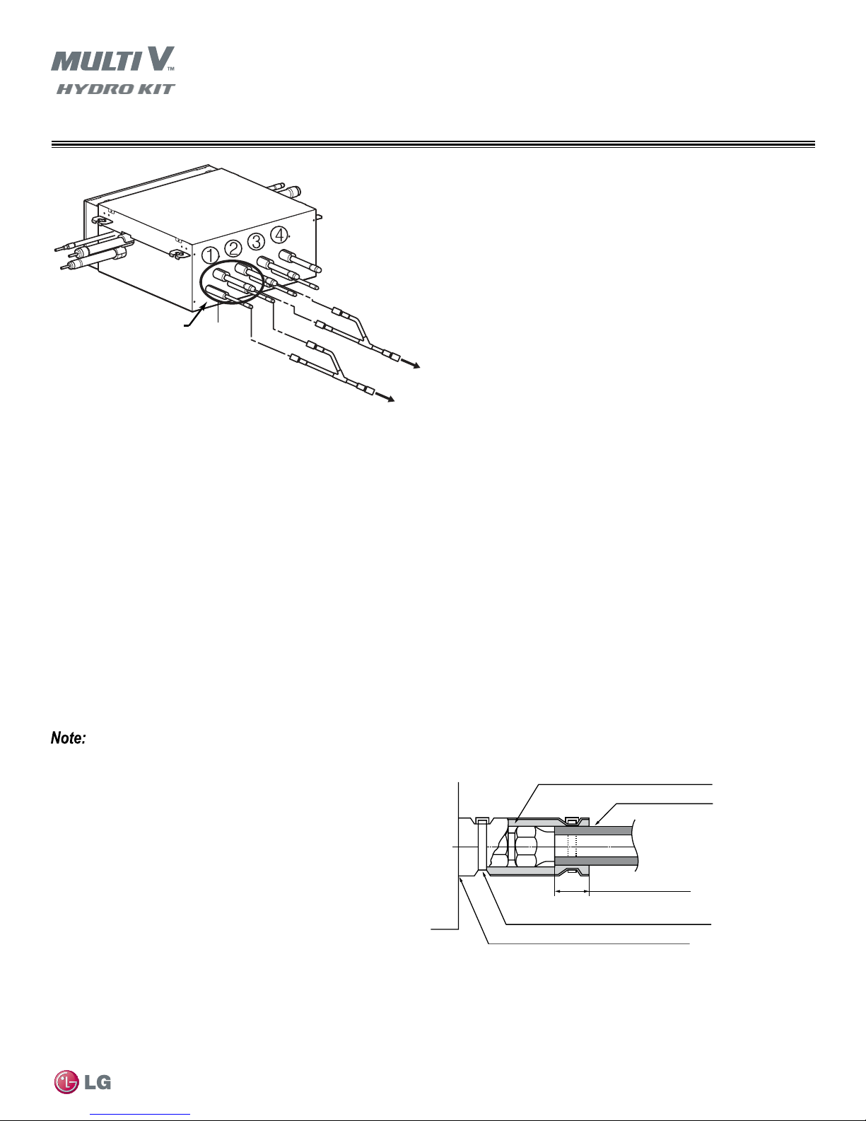
ROUGHING-IN
Piping
Refrigerant Piping
Refrigerant Safety
ASHRAE Standards 15-2010 and 34-2010 offer guidelines that address refrigerant safety and the maximum allowable concentration of refrigerant in an occupied space. Refrigerant will dissipate into the atmosphere, but a certain volume of air is required for this to occur safely.
For R410A refrigerant, the maximum allowable concentration of refrigerant is twenty-six (26) lbs. per 1,000 cubic feet of an occupied space.
Buildings with twenty-four (24) hour occupancy allow half of that concentration.
ASHRAE Standards 15 and 34 assume that if a system develops a leak, its entire refrigerant charge will dump into the area where the leak
occurs. To meet ASHRAE Standards 15 and 34, calculate the refrigerant concentration that may occur in the smallest room volume on the
system, and compare the results to the maximum allowable concentration number.1 Also consult state and local codes in regards to refrigerant safety.
Verify that the maximum refrigerant concentration level in the space where the indoor unit will be mounted meets the concentration limit for the
application.
Cutting the Pipes
•Use the accessory piping kit or use pipes purchased locally
(Figure 10).
•Measure the distance between the indoor and outdoor units.
•Cut the pipes a little longer than the measured distance.
1
Removal of Burrs
•Completely remove all burrs from the cut cross section of pipe/tube
(Figure 11).
MULTI V Hydro Kit Installation Manual
•Be sure the end of the copper tubing is pointed downward (toward
the floor) as you remove burrs. This will prevent the burrs from
falling back into the tubing.
Pipe Brazing
Make sure to flow Nitrogen during brazing. If brazing is done without
owing Nitrogen, it can generate a thick oxidized coating within the pipe
which will interfere with the normal operation of valve and compressor
(Figure 12).
Figure 10: Cutting Pipes
Figure 11: Removing Burrs for Piping
Figure 12: Brazing Pipes
1
Information about ASHRAE Standard 15-2010 / 34-2010 and addenda current as of the date of this publication.
Due to our policy of continuous product innovation, some specifications may change without notification.
24
©LG Electronics U.S.A., Inc., Englewood Cliffs, NJ. All rights reserved. “LG Life’s Good” is a registered trademark of LG Corp.
No Clearance
Insulation for Indoor Unit Port
Gas pipe 5/8 inch
Liquid pipe 3/8 inch
Gas pipe 7/8 inch
Liquid pipe 3/8 inch
Figure 13: Heat Recovery - Refrigerant Pipe Connections
ROUGHING-IN
Pipe Insulation
Heat Recovery System Unit
Refrigerant Pipe Connections
•When connected to a Heat Recovery Unit, the Hydro Kit requires
the use of two ports. If the capacity of the Hydro Kit and other
IDU’s connected to the Heat Recovery Unit are similar, install the
Hydro Kit on Ports 1 & 2.
•When twinning ports, the “twinned” pipes must be the same diam-
eter, layout, and length to balance the flow between the two
(Figure 13).
Hydro kit
Refrigerant Piping Support
A properly installed pipe system will have sufficient support so that
pipes will not sag during the life of the system. As necessary, place
supports looser for segments where potential sagging could occur.
Maximum spacing of pipe supports shall meet local codes
(Figure 14).
Pipe Insulation
To prevent condensate from forming on the surface of the insulation,
calculate the proper wall thickness required based on the ambient air
conditions of the surrounding area. Use calculation procedures provided
by the pipe insulation manufacturer.
•Use insulation material with high thermal resistance and rated
for the anticipated operating temperature range. If installing in a
humid environment, use thicker insulation material as specified by
system designer.
•Insulate all cold surfaces to prevent moisture/condensate from
forming.
•Insulate and wrap each pipe separately.
•Use field-provided half (1/2) of an inch thick (or better) closed cell
insulation.
Figure 14: Refrigerant Piping Support
Typical Refrigerant Line Connection
(Field Supplied)
Insulation Clip (Field Supplied)
Figure 15: Typical Refrigerant Line Joint Insulation Detail
Insulation Detail
Insulation for Refrigerant
Piping (Field Supplied)
Overlap Insulation Where the
Port and the Piping Meet
Installation
Due to our policy of continuous product innovation, some specifications may change without notification.
©LG Electronics U.S.A., Inc., Englewood Cliffs, NJ. All rights reserved. “LG Life’s Good” is a registered trademark of LG Corp.
25
ROUGHING-IN
Insulation over Pipe
Hydro Kit
Refrigerant Piping
Pipe Insulation - Continued
— The thickness may need to be increased based on ambient
conditions and local codes.
•Wrap all refrigerant and condensate piping, including field-provided
isolation ball valves and pipe connection kits provided by LG.
•Glue all insulation joints (see Figure 15).
— There should be no air gaps between insulation segments, or
between the insulation segments and the unit case.
— Fit insulation material snugly against refrigeration pipe. There
should be no air space between pipe surface and surrounding
insulation.
•Do not compress the insulation in areas where the piping passes
through pipe hangers, conduit, and/or wall sleeves.
— Protect insulation from compression inside hangers and sup-
ports by wrapping with a second layer.
Figure 16: Hydro Kit Pipe Insulation
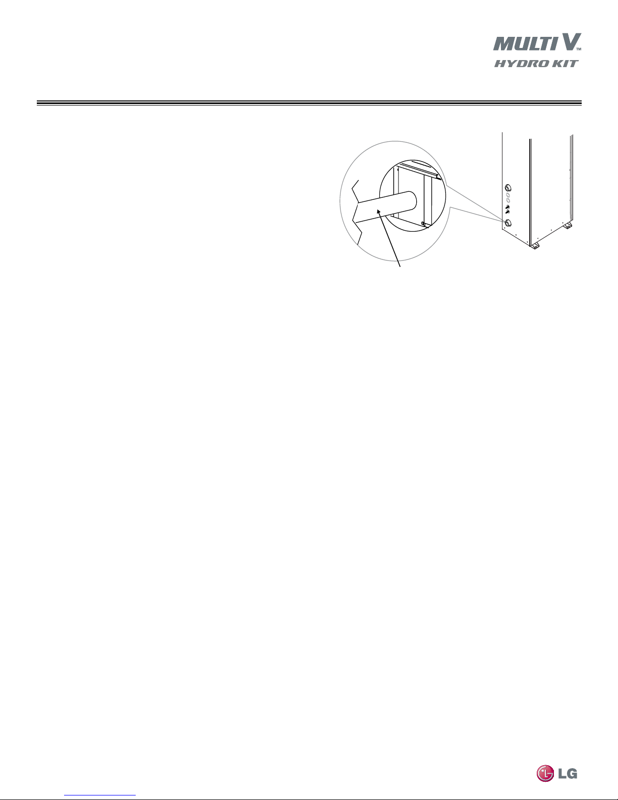
Condensate Piping for Hydro Kit High Temperature (K3) Only
•The Hydro Kit condensate line connection is designed to be a gravity drain. If a condensate pump is required, it shall be field provided and
installed external to the unit case.
•Slope drain line a minimum of 1/4” per foot of horizontal run away from the unit case. Properly vent the condensate line per industry standard
practices. See Figure 17.
While making pipe connections, be careful to support pipe to avoid placing lateral force on the drain nipple. Internal damage may occur.
•Condensate pipe connection is 1” male pipe thread.
MULTI V Hydro Kit Installation Manual
Figure 17: Typicalcondensateline(eldprovided-nottoscale)
Due to our policy of continuous product innovation, some specifications may change without notification.
26
©LG Electronics U.S.A., Inc., Englewood Cliffs, NJ. All rights reserved. “LG Life’s Good” is a registered trademark of LG Corp.
 Loading...