

LG MU-60PZ95V Service Manual

PLASMA MONITOR
SERVICE MANUAL
CAUTION
BEFORE SERVICING THE CHASSIS,
READ THE SAFETY PRECAUTIONS IN THIS MANUAL.
CHASSIS : RF-043E
MODEL : MU-60PZ95V
CANADA : http//biz.lgservice.com
USA : http//www.lgservice.com
: http//lgservice.com/techsup.html
- 2 -
SAFETY PRECAUTIONS
Many electrical and mechanical parts in this chassis have special safety-related characteristics. These parts are identified by in
the Schematic Diagram and Replacement Parts List.
It is essential that these special safety parts should be replaced with the same components as recommended in this manual to
prevent X-RADIATION, Shock, Fire, or other Hazards.
Do not modify the original design without permission of manufacturer.
General Guidance
An lsolation Transformer should always be used during
the servicing of a receiver whose chassis is not isolated from
the AC power line. Use a transformer of adequate power rating
as this protects the technician from accidents resulting in
personal injury from electrical shocks.
It will also protect the receiver and it's components from being
damaged by accidental shorts of the circuitary that may be
inadvertently introduced during the service operation.
If any fuse (or Fusible Resistor) in this monitor is blown, replace
it with the specified.
When replacing a high wattage resistor (Oxide Metal Film
Resistor, over 1W), keep the resistor 10mm away from PCB.
Keep wires away from high voltage or high temperature parts.
Due to high vacuum and large surface area of picture tube,
extreme care should be used in handling the Picture Tube.
Do not lift the Picture tube by it's Neck.
Leakage Current Cold Check(Antenna Cold Check)
With the instrument AC plug removed from AC source,
connect an electrical jumper across the two AC plug prongs.
Place the AC switch in the on positioin, connect one lead of
ohm-meter to the AC plug prongs tied together and touch other
ohm-meter lead in turn to each exposed metallic parts such as
antenna terminals, phone jacks, etc.
If the exposed metallic part has a return path to the chassis, the
measured resistance should be between 1MΩ and 5.2MΩ.
When the exposed metal has no return path to the chassis the
reading must be infinite.
An other abnormality exists that must be corrected before the
receiver is returned to the customer.
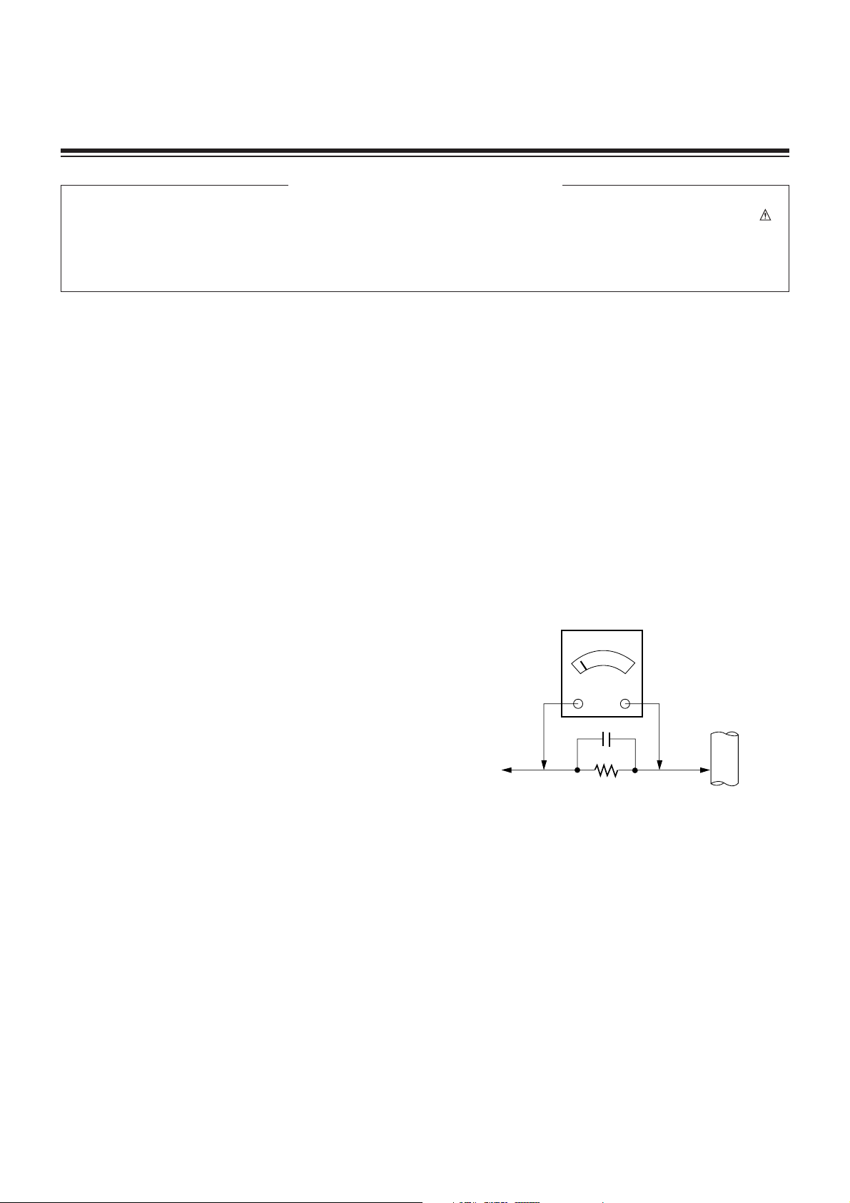
Leakage Current Hot Check (See below Figure)
Plug the AC cord directly into the AC outlet.
Do not use a line Isolation Transformer during this check.
Connect 1.5K/10watt resistor in parallel with a 0.15uF capacitor
between a known good earth ground (Water Pipe, Conduit, etc.)
and the exposed metallic parts.
Measure the AC voltage across the resistor using AC
voltmeter with 1000 ohms/volt or more sensitivity.
Reverse plug the AC cord into the AC outlet and repeat AC
voltage measurements for each esposed metallic part. Any
voltage measured must not exceed 0.75 volt RMS which is
corresponds to 0.5mA.
In case any measurement is out of the limits sepcified, there is
possibility of shock hazard and the set must be checked and
repaired before it is returned to the customer.
Leakage Current Hot Check circuit
CANADA: LG Electronics Canada, Inc. 550 Matheson
Boulevard East Mississauga, Ontario L4Z 4G3
USA : LG Customer Interactive Center
P.O.Box 240007, 201 James Record Road Huntsville,
AL 35824
Digital TV Hotline 1-800-243-0000
1.5 Kohm/10W
To Instrument's
exposed
METALLIC PARTS
Good Earth Ground
such as WATER PIPE,
CONDUIT etc.
AC Volt-meter
IMPORTANT SAFETY NOTICE
0.15uF

- 3 -
DESCRIPTION OF CONTROLS...........................................4
SPECIFICATIONS.................................................................6
ADJUSTMENT INSTRUCTIONS ..........................................7
TROUBLE SHOOTING GUIDE...........................................12
BLOCK DIAGRAM...............................................................23
EXPLODED VIEW...............................................................24
EXPLODED VIEW PARTS LIST.........................................25
REPLACEMENT PARTS LIST............................................26
SCHEMATIC DIAGRAM..........................................................
PRINTED CIRCUIT BOARD ...................................................
TABLE OF CONTENTS
- 4 -
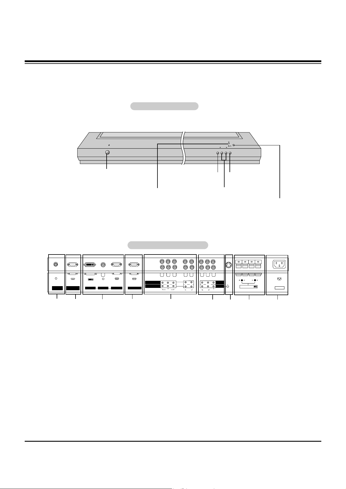
Controls
Controls
Connection Options
Connection Options
RS-232C INPUT
(CONTROL/SERVICE)
YPBP
R
AC INPUT
AUDIO INPUT
( )( )
( )
( )
EXTERNAL SPEAKER
DVI INPUT
RGB INPUT
RGB OUTPUT
S-VIDEO
AUDIO
VIDEO
MONITOR
OUTPUT
A/V
INPUT 1
(R)
(L)
VIDEO
(R)
(L/MONO)
R
L
AUDIO
COMPONENT INPUT 2
COMPONENT INPUT 1
REMOTE
CONTROL
5
1. REMOTE CONTROL
Connect your wired remote control to the remote control
port on the Monitor.
2. RS-232C INPUT (CONTROL/SERVICE) PORT
Connect to the RS-232C port on a PC.
3. DVI (Digital Visual Interface) INPUT/
AUDIO INPUT/ RGB INPUT JACKS
Connect the monitor output connector from a PC to the
appropriate input port.
4. RGB OUTPUT PORT
You can watch the RGB signal on another monitor, connect
RGB OUTPUT to another monitor’s PC input port.
5. DVD/DTV Input (Component 1-2)
Connect a component video/audio device to these jacks.
6. Monitor Output
Connect a second Monitor.
Audio/Video Input 1
Connect audio/video output from an external device to
these jacks.
7. S-Video Input
Connect S-Video out from an S-VIDEO device to the SVIDEO input.
8. EXTERNAL SPEAKER (8 ohm output)
Connect to optional external speaker(s).
* For further information, refer to ‘Speaker & Speaker
Stand’ manual.
9. POWER CORD SOCKET
This Monitor operates on an AC power. The voltage is indicated on the Specifications page. Never attempt to operate
the Monitor on DC power.
Back Connection Panel
Back Connection Panel
VOLUME
INPUT
SELECT
ON/OFF
Main Power Button
INPUT SELECT Button
VOLUME (
FF,GG
) Buttons
Remote Control Sensor
Power Standby Indicator
Illuminates red in standby
mode. Illuminates green when
the Monitor is turned on.
Sub Power Button
Front Panel Controls
Front Panel Controls
1
3
4
2
7 8
6
- This is a simplified representation of a typical front panel.
The Front Panel Controls shown here may be somewhat different from your monitor.
9
DESCRIPTION OF CONTROLS
- 5 -
- When using the remote control, aim it at the remote control sensor on the monitor.
- Under certain conditions such as if the remote IR signal is interrupted, the remote control may not function. Press
the key again as necessary.
1 2 3
4 5 6
7 8
0
9
POWER
SLEEP INPUT SELECT
APC DASP
ARC SPLIT ZOOM
PIP/DW
WIN.POSITION
SWAP
MENU MUTE
OK
VOL
POWER
REW
STOP
PLAY FF
REC
PAUSE
W
WIN.P
VOL
SUB INPUT
STOP P/STILL
REW
PLAY FF
POWER
VCR
DVD
OPEN/CLOSE
WIN.SIZE
SKIP
POWER
Switches the Monitor between
ON and STANDBY.
SLEEP
Sets the Sleep Timer.
APC
Adjusts the factory preset picture
according to the room.
ARC
Changes the picture format.
PIP/DW
Switches the sub picture on or off.
SWAP
Exchanges main and sub picture
images.
MENU
Displays on screen menus one by one.
Exits the current menu.
NUMBER buttons
VCR BUTTONS
Control some video cassette
recorders.
OK
DD / EE
Selects menu option.
Memorizes menu changes.
FF / GG
(Volume button)
Increases/decreases sound level.
Adjusts menu settings.
INPUT SELECT
Selects source:
RGB, DVI,
Component, Video or S-Video,mode.
DASP
To select the sound appropriate to
your viewing program character:
SRS TSXT, Flat, Music, Movie, Sports, or
Off
SPLIT ZOOM
Enlarges the picture.
SUB INPUT
Selects the input source for the sub
picture.
MUTE
Switches the sound on or off.
WIN.POSITION
Moves the sub picture.
Remote Control Key Functions
Remote Control Key Functions
DVD
Control some DVD cassette
recorders.
WIN.SIZE
Adjusts the sub picture size.
DESCRIPTION OF CONTROLS
- 6 -
• The specifications shown above may be changed without notice for quality improvement.
MODELS
Width (inches / mm)
Height (inches / mm)
Depth (inches / mm)
Weight (pounds / kg)
Power requirement
Resolution
Color
Operating Temperature Range
Operating Humidity Range
Maximum Elevation
MU-60PZ95V
57.3 / 1455
84.3 / 883
3.9 / 99
139 / 63
AC120V, 60Hz
1366 x 768 (Dot)
16,770,000 (256 steps of each R, G and B)
32 ~ 104°F (0 ~ 40°C)
Less than 80%
6561 feet (2000m)
SPECIFICATIONS
- 7 -
ADJUSTMENT INSTRUCTIONS
1. Application Object
These instructions apply to the RF-043E Chassis.
2. Specification
(1) Because this is not a hot chassis, it is not necessary to
use an isolation transformer. However, the use of isolation
transformer will help protect test equipment.
(2) Adjustment must be done in the correct order.
(3) The adjustment must be performed in the circumstance of
25±5°C of temperature and 65±10% of relative humidity if
there is no specific designation otherwise..
(4) The input voltage of the receiver must keep 100~220V,
50/60Hz.
(5) The receiver must be operated for about 15 minutes prior
to adjustments.
O The unit must be Heat Run with a RGB Full pattern, prior to
adjustment.
O Enter into HEAT-RUN MODE
1) Press the POWER ON KEY on Service R/C.
2) OSD display and screen display 100% full WHITE
PATTERN.
[ Set is activated HEAT-RUN without signal generator in
this mode.
[ Single color pattern(RED/BLUE/GREEN) of HEAT-RUN
mode can be used to check PANEL.
Caution) If you turn on a still screen for more than 20 minutes
(Especially digital pattern, cross hatch pattern), an
afterimage may occur in the black level part of the
screen.
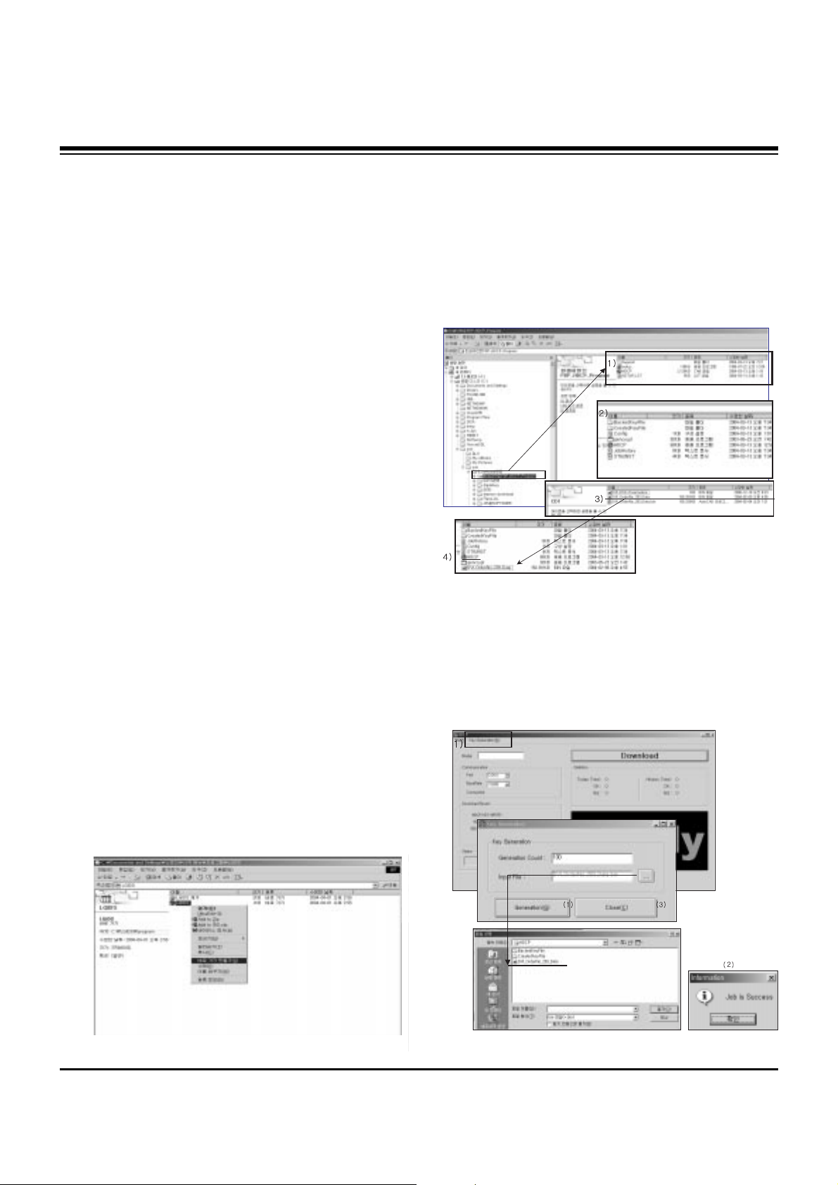
3. Setting Up the LGIDS
(1) Install the LGIDS. (idsinst.exe)
After installation has completed, check if the file shown in
(Fig. 1) has been created.
(2) Right click on 'LGIDS' and select ‘Create Shortcut’
Then move the shortcut icon onto the desktop.
(3) Double-click on the ‘LGIDS’ icon on the desktop to
execute the program.
4. HDCP Upload
4-1. Setting Up the LGIDS
(1) Click on ‘setup’ to install in your directory.
(2) After installation has completed, check if the file shown on
(Fig. 2) has been created.
(3) Copy the KEY from source CD into the HDCP directory
which was installed just now.
(DVI_orderNo_2003_data)
(4) After running HDCP(application program) which is inside
the HDCP directory, setup the Communication.
Port : COM1(modification possible)
BaudRate : 115200
4-2. KEY Generation
(Fig. 1)
(Fig. 2)
(Fig. 3)
- 8 -
ADJUSTMENT INSTRUCTIONS
(1) Click on ‘Key Generation (G)’.
(2) Input the number of the key in Generation count.
ex) If 100 Keys are required, then just register 100 and
next time it will automatically get 101.
(3) Input file : When installing the program for the first time,
you must find the original KEY that you copied and open it.
It is crucial that you copy the original KEY into this
directory.
When you use Generation, the information is recorded in
Config.ini.
(4) Click on ‘Generation’ ———————————————(1)
If it is done correctly, you will see “Job is Success.”——(2)
Click on ‘close’——————————————————(3)
(5) Check the Generation Data(Confirmation is possible within
HDCP\CreatedKeyFile)
(6) It is possible to check how many Generations are created
at this point.
(Fig. 5) shows that you have created 130 Generations and
you will start from 131 next time.
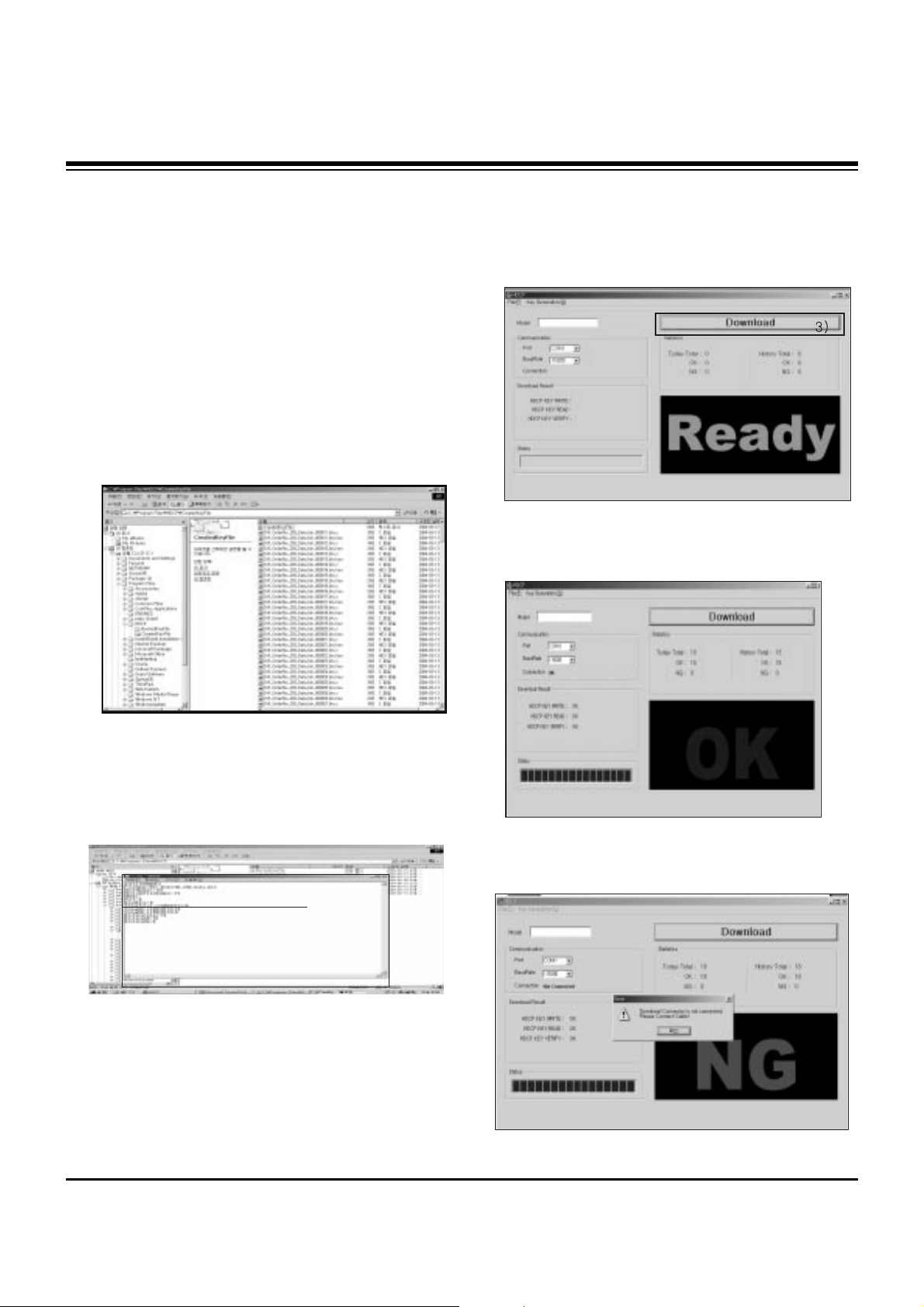
4-3. HDCP Upload Method
(1) The unit must be in Stand-By.
(Upload must be executed only when it is on Stand-by)
(2) The RS-232C(9PIN) must be connected to the COM1 on
the PC.
(3) If all the preparation is completed, click on ‘Download’.
(4) If you see NG the upload failed, start from step (3).
(Fig. 4)
(Fig. 5)
(Fig. 6)
(Fig. 8) Abnormal State
(Fig. 7) Normal State
- 9 -
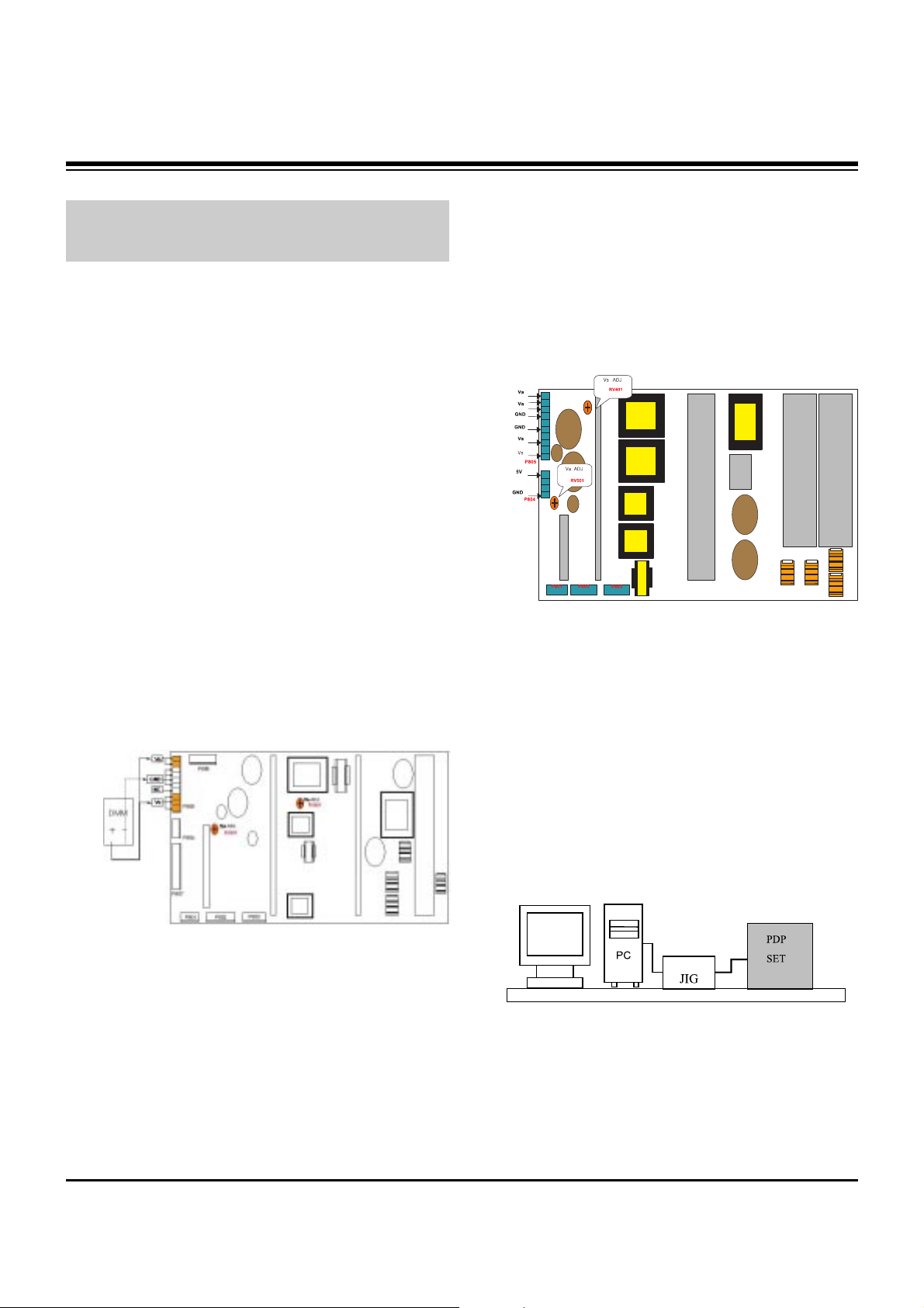
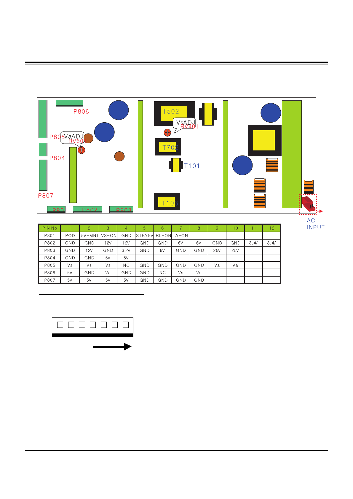
5. POWER PCB Assy Voltage
Adjustments
(Va, Vs Voltage Adjustments)
5-1. Test Equipment :D.M.M. 1EA
5-2. Connection Diagram for Measuring
Refer to (Fig 9).
5-3. Adjustment Method for
P/No. 3501V00182A/B B/D
(1) Va Adjustment
1) After receiving 100% Full White Pattern, HEAT RUN.
2) Connect + terminal of D.M.M to Va pin of P805, connect
- terminal to GND pin of P805.
3) Turn RV601, to adjust the Va voltage to match the value
marked on the label on the right/top of the panel.
(Deviation; ±0.5V)
(2) Vs Adjustment
1) Connect + terminal of D.M.M to Vs pin of P805, connect
– terminal to GND pin of P805.
2) Turn RV401, to adjust the Vs voltage to match the value
marked on the label on the right/top of the panel.
(Deviation; ±0.5V)
5-4. Adjustment Method for Power Supply
(1) Va Adjustment
1) After receiving 100% Full White Pattern, HEAT RUN.
2) Connect + terminal of D.M.M to Va pin of P805, connect
- terminal to GND pin of P805.
3) Turn RV501, to adjust the Va voltage to match the value
marked on the label on the right/top of the panel.
(Deviation; ±0.5V)
(2) Vs Adjustment
1) Connect + terminal of D.M.M to Vs pin of P805, connect
– terminal to GND pin of P805.
2) Turn RV401, to adjust the Vs voltage to match the value
marked on the label on the right/top of the panel.
(Deviation; ±0.5V)
6. DDC Data Input
6-1. Required Test Equipment
(1) A jig for adjusting PC, DDC (PC serial to D-sub
Connection equipment)
(2) S/W for writing DDC (EDID Data Write & Read)
(3) D-sub 15P Cable, D-Sub to DVI Connector (Connect to
DVI Jack)
6-2. Setting of Device
6-3. Preparation for Adjustment
(1) Set devices as above and turn the PC and jig on.
(2) Put S/W for writing DDC (EDID data Write & Read) into
operation. (operated in DOS mode.)
ADJUSTMENT INSTRUCTIONS
Each PCB assembly must be checked by Check JIG Set
before assembly. (Take special note of the Power PCB, which
can easily damage the PDP module)
(Fig. 9-1) Connection Diagram of Power Supply Part #
(3501V00182A/B)
(Fig. 9-2) Connection Diagram of Power Supply Part #
(3501V00187A)
(Fig. 10)
- 10 -
ADJUSTMENT INSTRUCTIONS
6-4. Sequence of Adjustment
(1) DDC Data Input for Analog-RGB
1) Put the set on the table and turn the power on.
2) Connect PC Serial to D-sub 15P Cable of jig for DDC
adjustment to RGB terminal (D-Sub 15Pin).
3) Operate S/W for DDC record and select DDC data for
Analog RGB in Model Menu.
4) Operate EDID Write command.
5) Operate EDID Read command and check whether
Check Sum is as below.
MU-42PM11: CB
MU-42PM12X/MU-50PM10: DC
6) If Check Sum is not CB(or DC), repeat 3) ~ 4).
7) If Check Sum is CB(or DC), DDC data for Analog-RGB
input is completed.
(2) DDC Data input for Digital-RGB(DVI)
1) Connect PC Serial to DVI Cable of jig for DDC
adjustment to DVI terminal (DVI Jack).
2) Operate S/W for DDC record and select DDC data for
digital RGB in model menu.
3) Operate EDID Write command.
4) Operate EDID Read command and check whether
Check sum is as below.
MU-42PM11: 4A
MU-42PM12X/MU-50PM10: CD
5) If Check sum is not 4A(or CD), repeat 3) ~ 4).
6) If Check sum is 4A(or CD), DDC data for Analog-RGB
input is completed.
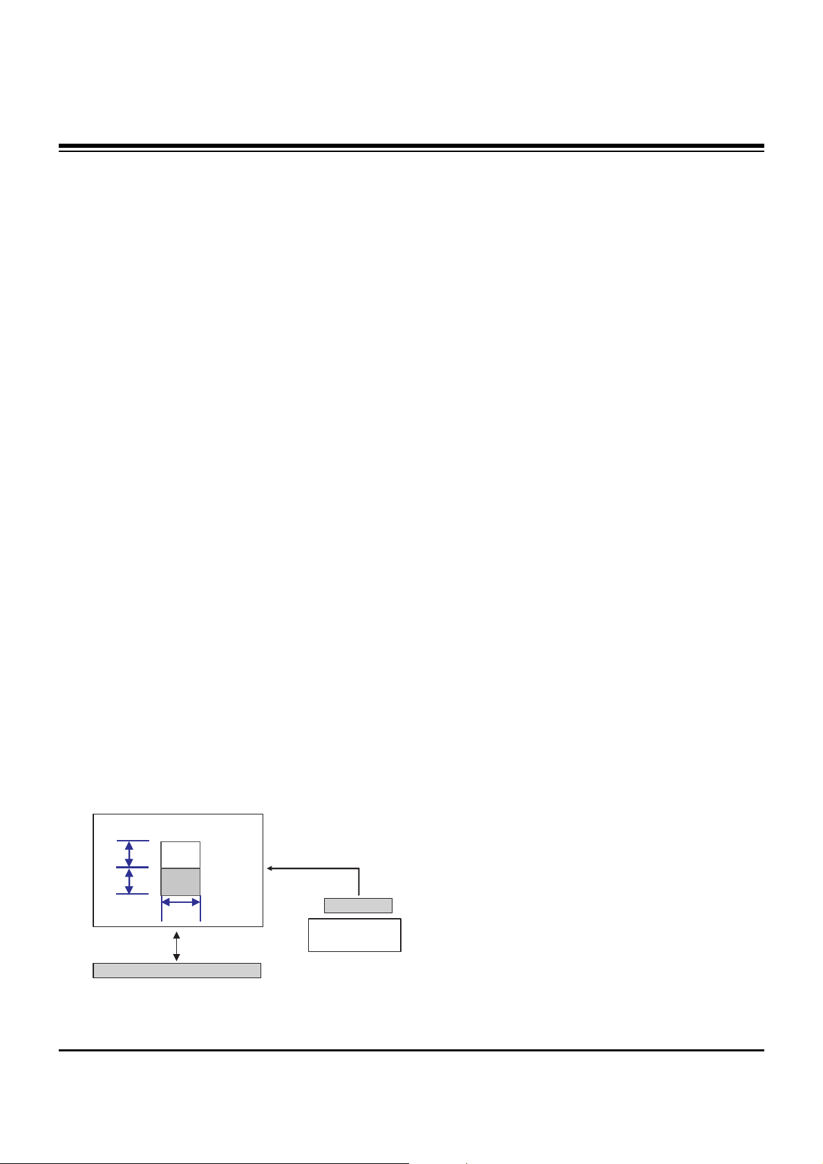
7. Adjustment of White Balance
7-1. Required Equipment
Color Analyzer (CA-100 or similar product)
7-2. Connection Diagram of Equipment for
Measuring
7-3. Adjustment of White Balance
O Operate the Zero-calibration of the CA-100, then stick
sensor to PDP module surface when you adjust.
O Manual adjustment is also possible by the following
sequence.
(1) Select white pattern of heat-run mode by pressing power
key on the Service Remote Control (S R/C) then allow to
heat run at least 15 minutes.
(2) Supply Window Pattern signal to DVI input using Pattern
Generator.
1) Input Signal: XGA 60Hz
2) Input the Window Pattern(Horizontal 25%, Vertical
50%(Top High 25% + Bottom Low 25%))
(Refer to Fig. 11)
(3) Press the FRONT-AV KEY on R/C for converting input to
DVI mode.
(4) Press ADJ key twice on Service R/C. (White Balance)
(5) High Adjustment
Stick sensor to center of 160 Gray Level(High Window
Pattern), select Red Gain and Green Gain using
D, E key
on S R/C.
Press VOL +, - keys to adjust until color coordination
matches below.
X; 0.285±0.003, Y; 0.285±0.003
(6) Low Adjustment
Stick sensor to center of 80 Gray Level(Low Window
Pattern), select Red Offset and Green Offset using
D, E
key on S R/C.
Press VOL +, - keys to adjust until color coordination
matches below.
X; 0.285±0.006, Y; 0.285±0.006
(7) Repeat above step (5) and (6) for the best condition of
High and Low.
(8) Exit adjustment mode using
A Key.
8. Auto Component Color Balance
8-1. Required Test Equipment
Pattern Equipment: MSP3240A or similar product
(16 Gray Scale Pattern output(Component output Level:
0.7Vp-p)
8-2. Method of Auto RGB Color Balance
(1) Input RGB Source : Component 720p 16 Gray Scale
Pattern
Input a Y, Pb and Pr signal.
(2) Press ADJ KEY on the S R/C.
(3) Press Vol. + KEY and operate To set.
(4) Auto-RGB OK means completed adjustment.
1/4 H
1/4 H
1/4 W
High
160 gray
Low
80 gray
RS-232C Serial Communication
DVI Signal Input
XGA 60Hz Signal
COLOR ANALYZER
TYPE; CA-100
Window
MSPG-2100 or
MSTG-5200
(Fig. 11) White Balance Adjustment
- 11 -
9. Auto RGB Color Balance
9-1. Required Test Equipment
Pattern Equipment: PC Pattern Generator (VG828, VG854,
801GF, MSP3240A)
(16 Gray Scale Pattern output(RGB output Level: 0.7Vp-p)
9-2. Auto RGB Color Balance
(1) Input RGB Source : XGA 60HZ 16 Gray Scale Pattern
(2) Press ADJ KEY on the Service R/C.
(3) Press Vol. + KEY and operate To SET.
(4) Auto-RGB OK means completed adjustment.
10. Auto Adjustment Map(RS-232C)
(Fig. 12) Auto RGB/ Component Color Balance Test Pattern
Type
Baud Rate
115200
Index
R Gain
G Gain
B Gain
R Offset
G Offset
B Offset
Data bit
8
Cmd1 Cmd2
j a
j b
j c
j d
j e
j f
Stop bit
1
Parity
NONE
RF-043A
Protocol
Setting
Data Min Value
00(00)
00(00)
00(00)
00(00)
00(00)
00(00)
Max Value
255(FF)
255(FF)
255(FF)
255(FF)
255(FF)
255(FF)
RS232
ADJUSTMENT INSTRUCTIONS
- 12 -
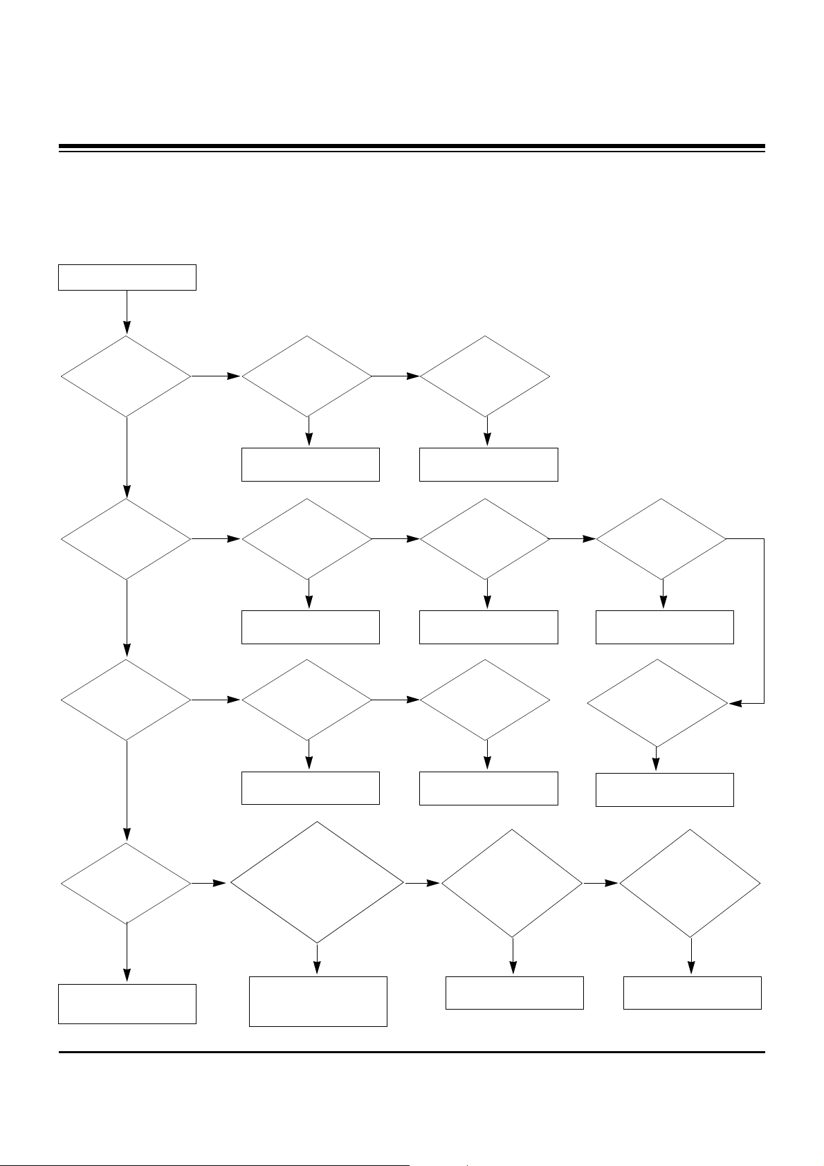
TROUBLE SHOOTING GUIDE
1. Power Board
1-1. General Power Flow
Start check
Manufacture enterprise
meaning of a passage
1. Check the Power Off
condition.
Doesn't the
screen whole come
out?
It is identical
with Power Off
condition?
Yes
Yes
No
No
No
No
No
2. Check the Interface
signal condition.
Is the Interface
signal operated?
Yes
3. Check the St-by 5V
signal circuit.
Doesn't the
low pressure output
come out?
Doesn't the
St-by 5V signal
come out?
Yes
Yes
No
4. Check the 5V Monitor
signal circuit.
Doesn't the
5V Monitor signal
come out?
Yes
7. Check the VSC Vs-ON
signal
Doesn't the
high tension output
come out?
Doesn't the
VSC signal Vs-ON
come out?
Yes
Yes
High tension
output voltage Drop
it occurs?
When
remove the
Y B/D Module
Input Connector, output
voltage Drop
it occurs?
When remove
the Y, Z B/D Module
Input Connector, Power
Board high tension output
voltage Drop
it occurs?
Yes No No
9. Check the Power
Board Output high
tension circuit
Yes
10. Check the Z B/D
Module Coutput circuit
Yes
When
remove the
Z B/D Module
Input Connector, output
voltage Drop
it occurs?
11. Check the Y B/D
Module Coutput circuit
Yes
No
8. Check the Vs, Va
voltage output circuit.
Doesn't the
Vs, Va voltage output
come out?
Yes
No
No
5. Check the VSC RL-ON
signal.
Doesn't the
VSC signal RL-ON
come out?
Yes
6. Check the VSC low
pressure output
Doesn't the
VSC low pressure
output come out?
Yes
- 13 -
TROUBLE SHOOTING GUIDE
1-2. 3510V00182A Power Board Structure
T502: Vs Trans
T702: Va Trans
T101: St-by Trans
T103: Low Voltage Trans
1 2 3
 Loading...