

LG MU-60PZ90V, MU-60PZ90M, MU-60PZ90C Service Manual

PLASMA MONITOR
SERVICE MANUAL
CAUTION
BEFORE SERVICING THE CHASSIS,
READ THE SAFETY PRECAUTIONS IN THIS MANUAL.
CHASSIS : RF-03LA
MODEL : MU-60PZ90V/M/C
CANADA : http//biz.lgservice.com
USA : http//www.lgservice.com
: http//lgservice.com/techsup.html
http://www.wjel.net
- 2 -
SAFETY PRECAUTIONS
Many electrical and mechanical parts in this chassis have special safety-related characteristics. These parts are identified by in
the Schematic Diagram and Replacement Parts List.
It is essential that these special safety parts should be replaced with the same components as recommended in this manual to
prevent X-RADIATION, Shock, Fire, or other Hazards.
Do not modify the original design without permission of manufacturer.
General Guidance
An lsolation Transformer should always be used during
the servicing of a receiver whose chassis is not isolated from
the AC power line. Use a transformer of adequate power rating
as this protects the technician from accidents resulting in
personal injury from electrical shocks.
It will also protect the receiver and it's components from being
damaged by accidental shorts of the circuitary that may be
inadvertently introduced during the service operation.
If any fuse (or Fusible Resistor) in this monitor is blown, replace
it with the specified.
When replacing a high wattage resistor (Oxide Metal Film
Resistor, over 1W), keep the resistor 10mm away from PCB.
Keep wires away from high voltage or high temperature parts.
Due to high vacuum and large surface area of picture tube,
extreme care should be used in handling the Picture Tube.
Do not lift the Picture tube by it's Neck.
Leakage Current Cold Check(Antenna Cold Check)
With the instrument AC plug removed from AC source,
connect an electrical jumper across the two AC plug prongs.
Place the AC switch in the on positioin, connect one lead of
ohm-meter to the AC plug prongs tied together and touch other
ohm-meter lead in turn to each exposed metallic parts such as
antenna terminals, phone jacks, etc.
If the exposed metallic part has a return path to the chassis, the
measured resistance should be between 1MΩ and 5.2MΩ.
When the exposed metal has no return path to the chassis the
reading must be infinite.
An other abnormality exists that must be corrected before the
receiver is returned to the customer.
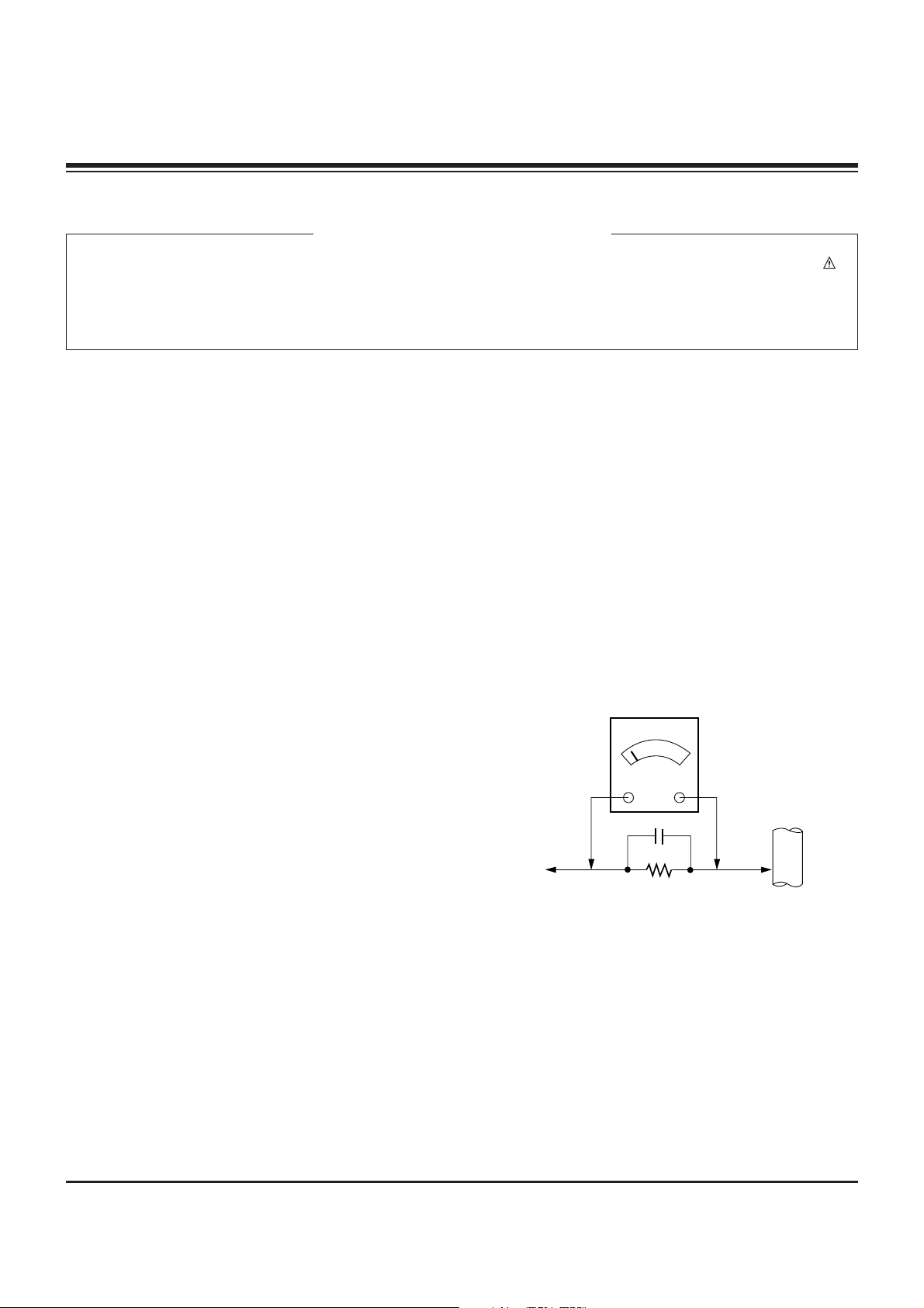
Leakage Current Hot Check (See below Figure)
Plug the AC cord directly into the AC outlet.
Do not use a line Isolation Transformer during this check.
Connect 1.5K/10watt resistor in parallel with a 0.15uF capacitor
between a known good earth ground (Water Pipe, Conduit, etc.)
and the exposed metallic parts.
Measure the AC voltage across the resistor using AC
voltmeter with 1000 ohms/volt or more sensitivity.
Reverse plug the AC cord into the AC outlet and repeat AC
voltage measurements for each esposed metallic part. Any
voltage measured must not exceed 0.75 volt RMS which is
corresponds to 0.5mA.
In case any measurement is out of the limits sepcified, there is
possibility of shock hazard and the set must be checked and
repaired before it is returned to the customer.
Leakage Current Hot Check circuit
CANADA: LG Electronics Canada, Inc. 550 Matheson
Boulevard East Mississauga, Ontario L4Z 4G3
USA : LG Customer Interactive Center
P.O.Box 240007, 201 James Record Road Huntsville,
AL 35824
Digital TV Hotline 1-800-243-0000
1.5 Kohm/10W
To Instrument's
exposed
METALLIC PARTS
Good Earth Ground
such as WATER PIPE,
CONDUIT etc.
AC Volt-meter
IMPORTANT SAFETY NOTICE
0.15uF
http://www.wjel.net

- 3 -
DESCRIPTION OF CONTROLS...........................................4
SPECIFICATIONS.................................................................6
EXTERNAL CONTROL DEVICE SETUP..............................8
IR CODE..............................................................................14
ADJUSTMENT INSTRUCTION...........................................16
PRINTED CIRCUIT BOARD ...............................................19
BLOCK DIAGRAM...............................................................29
EXPLODED VIEW...............................................................30
EXPLODED VIEW PARTS LIST.........................................31
REPLACEMENT PARTS LIST............................................32
SCHEMATIC DIAGRAM..........................................................
TABLE OF CONTENTS
http://www.wjel.net
- 4 -
Controls
Controls
Connection Options
Connection Options
RS-232C INPUT
(CONTROL/SERVICE)
VIDEO
INPUT
YPBP
R
(MONO)
R
AUDIO
L
R
AUDIO
L
S-VIDEO
AC INPUT
AUDIO INPUT
AUDIO INPUT
AUDIO INPUT
R
( )( )
( )
( )
L
EXTERNAL SPEAKER
COMPONENT INPUT
DVI INPUT
RGB INPUT
RGB OUTPUT
REMOTE CONTROL
5
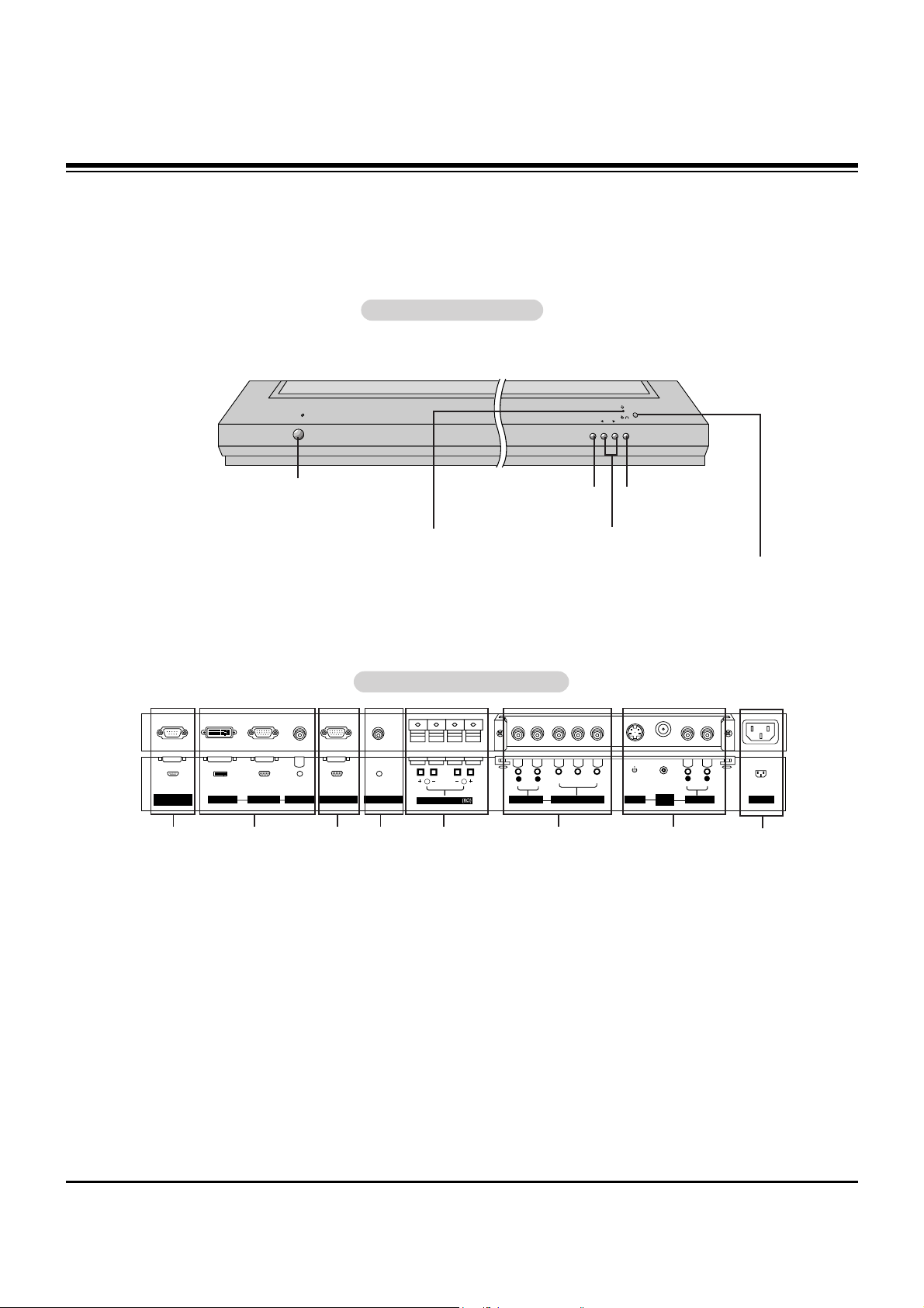
1. RS-232C INPUT (CONTROL/SERVICE) PORT
Connect to the RS-232C port on a PC.
2. DVI (Digital Visual Interface) INPUT/
RGB INPUT/AUDIO INPUT JACKS
Connect the monitor output connector from a PC to the
appropriate input port.
3. RGB OUTPUT PORT
You can watch the RGB signal on another monitor, connect
RGB OUTPUT to another monitor’s PC input port.
4. REMOTE CONTROL
Connect your wired remote control to the remote control
port on the Monitor.
5. EXTERNAL SPEAKER (8 ohm output)
Connect to optional external speaker(s).
* For further information, refer to ‘Speaker & Speaker
Stand’ manual.
6. COMPONENT INPUT/AUDIO INPUT JACKS
Connect a component video/audio device to these jacks.
7. S-VIDEO INPUTS
Connect S-Video out from an S-VIDEO VCR or other SVideo device to the S-VIDEO input.
AUDIO/VIDEO INPUT JACKS
Connect audio/video out from external equipment to these
jacks.
8. POWER CORD SOCKET
This Monitor operates on an AC power. The voltage is indicated on the Specifications page. Never attempt to operate
the Monitor on DC power.
Back Connection Panel
Back Connection Panel
VOLUME
INPUT
SELECT
ON/OFF
Main Power Button
INPUT SELECT Button
VOLUME (
F,G
) Buttons
Remote Control Sensor
Power Standby Indicator
Illuminates red in standby
mode. Illuminates green when
the Monitor is turned on.
Sub Power Button
Front Panel Controls
Front Panel Controls
1 3 42 7
8
6
- This is a simplified representation of a typical front panel.
The Front Panel Controls shown here may be somewhat different from your monitor.
DESCRIPTION OF CONTROLS
http://www.wjel.net

- 5 -
- When using the remote control, aim it at the remote control sensor on the monitor.
- Under certain conditions such as if the remote IR signal is interrupted, the remote control may not function. Press
the key again as necessary.
1 2 3
4 5 6
7 8
0
9
POWER
SLEEP INPUT SELECT
APC DASP
ARC PIP ARC
PIP
TWIN PICTURE
SWAP
MENU MUTE
OK
VOL
POWER STOP
PLAY FF
REC
REW
P/STILL
WIN.SIZE
WIN.POSITION
ZOOM +
ZOOM -
SPLIT ZOOM
VOL
SUB INPUT
POWER
Switches the Monitor between
ON and STANDBY.
SLEEP
Sets the Sleep Timer.
APC
Adjusts the factory preset picture
according to the room.
ARC
Changes the picture format.
PIP
Switches the sub picture on or off.
SWAP
Exchanges main and sub picture
images.
MENU
Displays on screen menus one by one.
Exits the current menu.
NUMBER buttons
WIN. SIZE
Adjusts the sub picture size.
WIN.POSITION
Moves the sub picture.
SPLIT ZOOM
Enlarges the picture.
ZOOM-/ZOOM+
Enlarges or reduces
the main picture size.
VCR BUTTONS
Control some video cassette
recorders.
OK
DD / EE
Selects menu option.
Memorizes menu changes.
FF / GG
(Volume button)
Increases/decreases sound level.
Adjusts menu settings.
INPUT SELECT
Selects source:
Video, S-Video, RGB,
DVI, or Component mode.
DASP
To select the sound appropriate to
your viewing program character:
Flat, Music, Cinema, Sports, or User
PIP ARC
Changes the PIP picture format.
SUB INPUT
Selects the input source for the sub
picture.
MUTE
Switches the sound on or off.
TWIN PICTURE
Remote Control Key Functions
Remote Control Key Functions
DESCRIPTION OF CONTROLS
http://www.wjel.net

- 6 -
Resolution
640x350
720x400
640x480
800x600
848x480
Horizontal
Frequency(KHz)
31.468
37.861
31.469
37.927
31.469
35.000
37.861
37.500
43.269
35.156
37.879
46.875
53.674
49.725
31.500
35.000
37.500
70.09
85.08
70.08
85.03
59.94
66.66
72.80
75.00
85.00
56.25
60.31
75.00
85.06
74.55
60.00
70.00
75.00
31.500
35.000
37.500
48.363
56.476
60.023
54.348
63.995
67.500
60.000
63.981
47.700
59.625
47.700
59.625
60.00
70.00
75.00
60.00
70.06
75.02
60.05
70.01
75.00
60.00
60.02
60.00
75.02
60.00
75.02
Vertical
Frequency(Hz)
Resolution
832x624
1024x768
852x480
1152x864
1280x960
1280x1024
1360x768
1366x768
Horizontal
Frequency(KHz)
Vertical
Frequency(Hz)
Monitor Display Specifications (RGB-PC / DVI-PC Mode)
SPECIFICATIONS
http://www.wjel.net

- 7 -
Product Specifications
Product Specifications
MODELS
Width (inches / mm)
Height (inches / mm)
Depth (inches / mm)
Weight (pounds / kg)
Power requirement
Resolution
Color
Operating Temperature Range
Operating Humidity Range
Maximum Elevation
MU-60PZ90M / MU-60PZ90V
57.3 / 1455
84.3 / 883
3.9 / 99
144 / 65.3
AC120V, 60Hz
1366 x 768 (Dot)
16,770,000 (256 steps of each R, G and B)
32 ~ 104°F (0 ~ 40°C)
Less than 80%
6561 feet (2000m)
SPECIFICATIONS
http://www.wjel.net
- 8 -
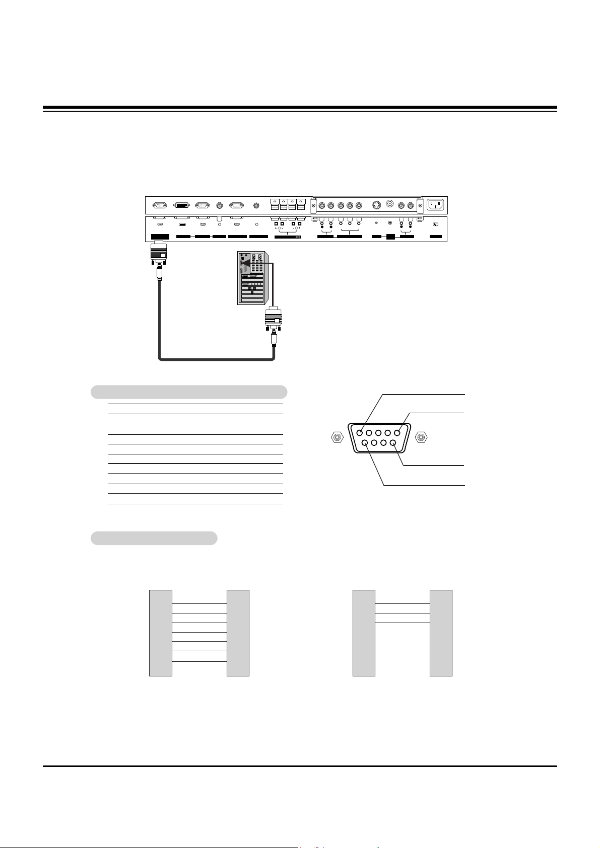
No. Pin Name
1 No Connection
2 RXD (Receive data)
3 TXD (Transmit data)
4 DTR (DTE side ready)
5 GND
6 DSR (DCE side ready)
7 RTS (Ready to send)
8 CTS (Clear to send)
9 No Connection
1
5
6
9
2
3
5
4
6
7
8
RXD
TXD
GND
DTR
DSR
RTS
CTS
TXD
RXD
GND
DSR
DTR
CTS
RTS
PC
7-Wire Configuration
(Standard RS-232C cable)
D-Sub 9
3
2
5
6
4
8
7
PDP
D-Sub 9
2
3
5
4
6
7
8
RXD
TXD
GND
DTR
DSR
RTS
CTS
TXD
RXD
GND
DTR
DSR
RTS
CTS
PC
3- Wire Configuration
(Non standard)
D-Sub 9
3
2
5
4
6
7
8
PDP
D-Sub 9
- Connect the RS-232C input jack to an external control device (such as a computer or an A/V control system)
and control the Monitor’s functions externally.
- Connect the serial port of the control device to the RS-232C jack on the Monitor back panel.
- RS-232C connection cables are not supplied with the Monitor.
TType of Connector: D-Sub 9-pin Male
ype of Connector: D-Sub 9-pin Male
RS-232C Configurations
RS-232C Configurations
RS-232C INPUT
(CONTROL/SERVICE)
VIDEO
INPUT
Y PBP
R
(MONO)
R
AUDIO
L
R
AUDIO
L
S-VIDEO
AC INPUT
AUDIO INPUT
AUDIO INPUT
AUDIO INPUT
R
( )( )
( )
( )
L
EXTERNAL SPEAKER
COMPONENT INPUT
DVI INPUT
RGB INPUT
RGB OUTPUT
REMOTE CONTROL
EXTERNAL CONTROL DEVICE SETUP
http://www.wjel.net

- 9 -
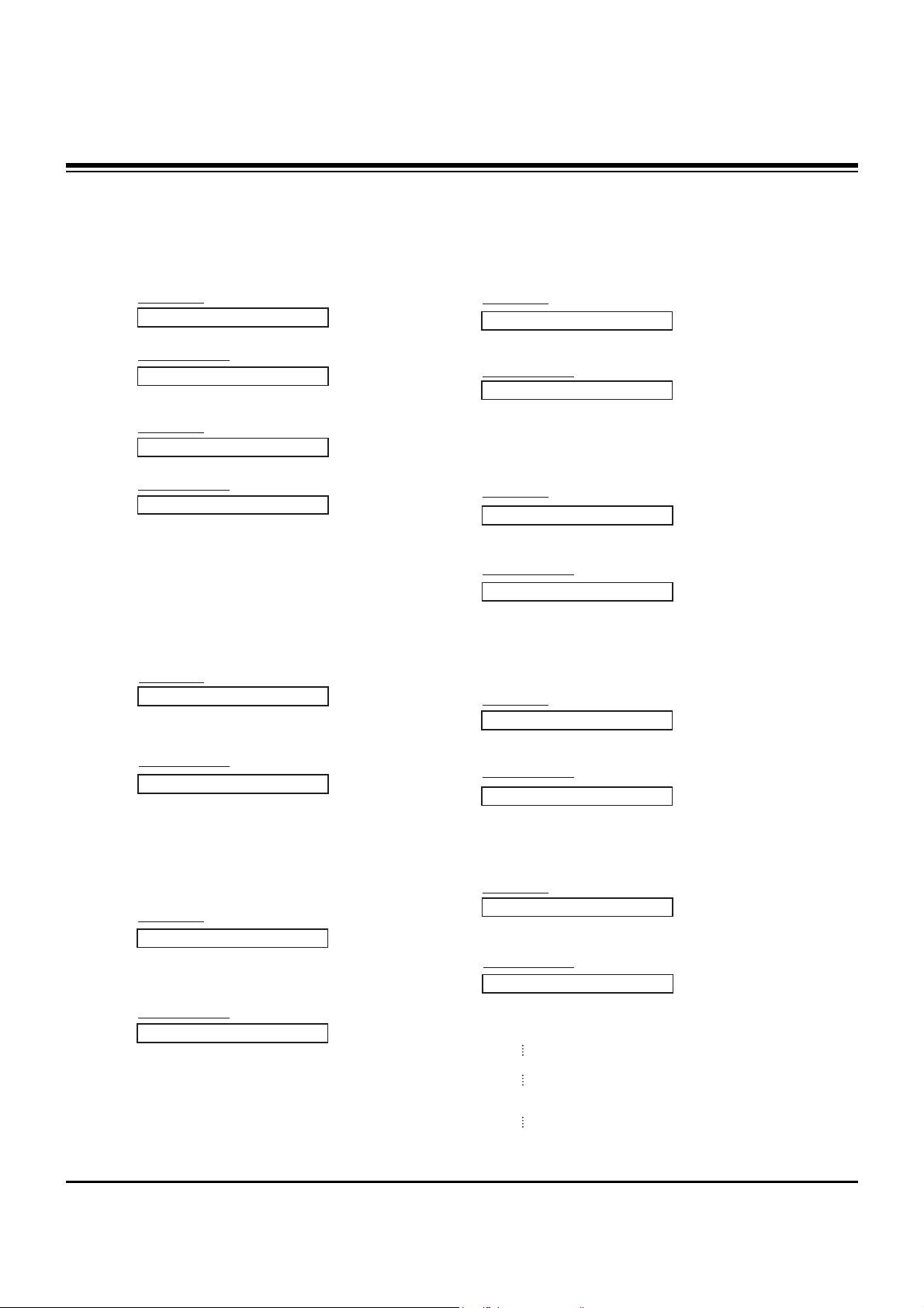
Transmission
*
[Command 1]: k, j
*
[Command 2]: To control PDP set.
*
[Set ID]: You can adjust the set ID to choose desired moni-
tor ID number in Special menu. Adjustment range
is 1 ~ 99. When selecting Set ID ‘0’, every connected PDP set is controlled. Set ID is indicated
as decimal (1~99) on menu and as Hexa decimal
(0x0~0x63) on transmission/receiving protocol.
*
[DATA]: To transmit command data.
Transmit ‘FF’ data to read status of command.
*
[Cr]: Carriage Return
ASCII code ‘0x0D’
*
[ ]: ASCII code ‘space (0x20)’
[Command1][Command2][ ][Set ID][ ][Data][Cr]
OK Acknowledgement
* The Monitor transmits ACK (acknowledgement) based on
this format when receiving normal data. At this time, if the
data is data read mode, it indicates present status data. If
the data is data write mode, it returns the data of the PC
computer.
[Command2][ ][Set ID][ ][OK][Data][x]
Error Acknowledgement
* The Monitor transmits ACK (acknowledgement) based on
this format when receiving abnormal data from
non-viable functions or communication errors.
[Command2][ ][Set ID][ ][NG][x]
TTransmission / Receiving Protocol
ransmission / Receiving Protocol
01. Power k a 0 ~ 1
02. Input Select k b 0 ~ 4
03. Aspect Ratio k c 0 ~ 3
04. Screen Mute k d 0 ~ 1
05. Volume Mute k e 0 ~ 1
06. Volume Control k f 0 ~ 64
07. Contrast k g 0 ~ 64
08. Brightness k h 0 ~ 64
09. Color k i 0 ~ 64
10. Tint k j 0 ~ 64
11. Sharpness k k 0 ~ 64
12. OSD Select k l 0 ~ 1
13.
Remote Control Lock Mode
k m 0 ~ 1
14. PIP/Twin k n 0 ~ 3
15. PIPAspect Ratio k o 0 ~ 1
16. Split Zoom k p 21 ~99
17. PIP Position k q 0 ~ 3
18. Treble k r 0 ~ 64
19. Bass k s 0 ~ 64
20. Balance k t 0 ~ 64
21. Color Temperature k u 0 ~ 3
22. Red Adjustment k v 0 ~ C8
23. Green Adjustment k w 0 ~ C8
24. Blue Adjustment k $ 0 ~ C8
25. PIP Input Source k y 0 ~ 4
26. Abnormal State k z 0 ~ a
27. ISM Method j p 0 ~ 3
28. Low Power j q 0 ~ 1
29. Orbiter Time Setting j r 1 ~ FE
30. Orbiter Pixel Setting j s 0 ~9
31. Picture Size Setting j t 0 ~64
for Twin Picture mode
32. Auto Configure j u 1
COMMAND 1 COMMAND 2 DATA
(Hexadecimal)
• Menu doesn’t display on screen when setting the 4,
12, 13, and 26 ~ 32.
Command Reference List
Command Reference List
Set ID
Set ID
- Use this function to specify a monitor ID number.
- Refer to ‘Real Data Mapping 1’. See page 27.
1. Press the MENU button and then use the
DD /EE
button to select the SPECIAL menu.
2. Press the GGbutton and then use
DD /EE
button to select Set ID..
3. Press the GGbutton and then use F / G button to adjust Set ID. to choose the desired
monitor ID number.
• The adjustment range of Set ID. is 1 ~ 99.
1
VIDEO
AUDIO
TIME
SCREEN
TWIN
SPECIAL
language
Key lock
ISM Method
Low power
Set ID. G
OSD Rotate
MENU
Prev.
• Baud rate : 115200 bps (UART)
• Data length : 8 bits
• Parity : None
• Stop bit : 1 bit
• Communication code : ASCII code
Communication Parameters
Communication Parameters
Data 1: Illegal Code
2: Not supported function
3: Wait more time
Component
Video
EXTERNAL CONTROL DEVICE SETUP
http://www.wjel.net
- 10 -
02. Input Select (Command:b) (Main Picture Input)
G To select input source for the Monitor.
You can also select an input source using the INPUT
SELECT button on the Monitor's remote control.
Transmission
Data 0 : RGB
1 : Component
2 : Video
3 : S-video
4 : DVI
[k][b][ ][Set ID][ ][Data][Cr]
Acknowledgement
[b][ ][Set ID][ ][OK][Data][x]
01. Power (Command:a)
G To control Power On/Off of the Monitor.
Transmission
Data 0 : Power Off 1 : Power On
[k][a][ ][Set ID][ ][Data][Cr]
Acknowledgement
[a][ ][Set ID][ ][OK][Data][x]
G To show Power On/Off.
Transmission
[k][a][ ][Set ID][ ][FF][Cr]
Acknowledgement
Data 0 : Power Off 1 : Power On
* In a like manner, if other functions transmit ‘FF’ data
based on this format, Acknowledgement data feedback
presents status about each function.
[a][ ][Set ID][ ][OK][Data][x]
03. Aspect Ratio (Command:c) (Main Picture Format)
G To adjust the screen format.
You can also adjust the screen format using the ARC
(Aspect Ratio Control) button on remote control or in the
Special menu.
Transmission
Data 0 : Wide screen (16:9)
1 : Normal screen (4:3)
2 : Full screen (Zoom)
3 : Horizon
[k][c][ ][Set ID][ ][Data][Cr]
Acknowledgement
* You select either 16:9 or 4:3 screen aspect ratio using the
PC, DTV 720p/1080i.
[c][ ][Set ID][ ][OK][Data][x]
05. Volume Mute (Command:e)
G To control volume mute on/off.
You can also adjust mute using the MUTE button on
remote control.
Transmission
Data 0 : Volume mute on (Volume off)
1 : Volume mute off (Volume on)
[k][e][ ][Set ID][ ][Data][Cr]
Acknowledgement
[e][ ][Set ID][ ][OK][Data][x]
04. Screen Mute (Command:d)
G To select screen mute on/off.
Transmission
Data 0 : Screen mute off (Picture on)
1 : Screen mute on (Picture off)
[k][d][ ][Set ID][ ][Data][Cr]
Acknowledgement
[d][ ][Set ID][ ][OK][Data][x]
06. Volume Control (Command:f)
G To adjust volume.
You can also adjust sound level with the volume buttons on remote control.
Transmission
Data Min : 0 ~ Max : 64
• Refer to ‘Real Data Mapping1’ as shown below.
[k][f][ ][Set ID][ ][Data][Cr]
Acknowledgement
[f][ ][Set ID][ ][OK][Data][x]
07. Contrast (Command:g)
G To adjust screen contrast.
You can also adjust contrast in the Video menu.
Transmission
Data Min : 0 ~ Max : 64
• Refer to ‘Real Data Mapping1’ as shown below.
[k][g][ ][Set ID][ ][Data][Cr]
Acknowledgement
[g][ ][Set ID][ ][OK][Data][x]
*
Real Data Mapping 1
0 : Step 0
A : Step 10 (SET ID 10)
F : Step 15 (SET ID 15)
10 : Step 16 (SET ID 16)
64 : Step 100
EXTERNAL CONTROL DEVICE SETUP
http://www.wjel.net

- 11 -
13. Remote Control Lock Mode (Command2:m)
G To lock the remote control and front panel controls on the
monitor
Transmission
[k][m][ ][Set ID][ ][Data][Cr]
Acknowledgement
Data 0: Lock off 1: Lock on
• If you’re not using the remote control and front panel con-
trols on the monitor, use this mode. When main power is
turned on/off, remote control lock is released.
[m][ ][Set ID][ ][OK][Data][x]
14. PIP / Twin (Command2:n)
G To control the PIP(Picture-in-Picture) or Twin Picture.
You can also control the PIP/TWIN using the PIP or T win PICTURE button on the remote control or in the Special menu.
Transmission
Data 0: PIP/DW off
1: PIP
2: DW1
3: DW2
[k][n][ ][Set ID][ ][Data][Cr]
Acknowledgement
[n][ ][Set ID][ ][OK][Data][x]
G To adjust the screen sharpness.
You can also adjust sharpness in the Video menu.
Transmission
11. Sharpness (Command2:k)
Data Min: 0 ~ Max: 64
• Refer to ‘Real Data Mapping 1’. See page 27.
[k][k][ ][Set ID][ ][Data][Cr]
Acknowledgement
[k][ ][Set ID][ ][OK][Data][x]
12. OSD Select (Command2:l)
G To select OSD (On Screen Display) on/off.
Transmission
[k][l][ ][Set ID][ ][Data][Cr]
Acknowledgement
Data 0: OSD off 1: OSD on
[l][ ][Set ID][ ][OK][Data][x]
15. PIP Aspect Ratio (Command2:o)
G To select the PIPpicture format.
You can also select the PIPpicture format using PIP ARC
on the remote control.
Transmission
[k][o][ ][Set ID][ ][Data][Cr]
Acknowledgement
Data 0: 4:3 1: 16:9
[o][ ][Set ID][ ][OK][Data][x]
09. Color (Command2:i)
G To adjust the screen color.
You can also adjust color in the Video menu.
Transmission
Data Min : 0 ~ Max : 64
• Refer to ‘Real Data Mapping 1’. See page 27.
[k][i][ ][Set ID][ ][Data][Cr]
Acknowledgement
[i][ ][Set ID][ ][OK][Data][x]
10. Tint (Command2:j)
G To adjust the screen tint.
You can also adjust tint in the Video menu.
Transmission
Data Red : 0 ~ Green : 64
• Refer to ‘Real Data Mapping 1’. See page 27.
[k][j][ ][Set ID][ ][Data][Cr]
Acknowledgement
[j][ ][Set ID][ ][OK][Data][x]
08. Brightness (Command2:h)
G To adjust screen brightness.
You can also adjust brightness in the Video menu.
Transmission
Data Min : 0 ~ Max : 64
• Refer to ‘Real Data Mapping 1’. See page 27.
[k][h][ ][Set ID][ ][Data][Cr]
Acknowledgement
[h][ ][Set ID][ ][OK][Data][x]
16. Split Zoom (Command2:p)
G To operate split zoom function and select the split
zoom section number.
Transmission
Data Min: 0 ~ Max: 99
• Refer to ‘Real Data Mapping 2’ below.
[k][p][ ][Set ID][ ][Data][Cr]
Acknowledgement
[p][ ][Set ID][ ][OK][Data][x]
*
Real Data Mapping 2
0 : Reset split zoom
21: Selection 1 of 2 split zoom
24: Selection 4 of 2 split zoom
41: Selection 1 of 4 split zoom
42: Selection 2 of 4 split zoom
44: Selection 4 of 4 split zoom
45: Selection 5 of 4 split zoom
91: Selection 1 of 9 split zoom
99: Selection 9 of 9 split zoom
EXTERNAL CONTROL DEVICE SETUP
http://www.wjel.net
- 12 -
21. Color Temperature (Command2:u)
G To adjust color temperature.
You can also adjust ACC in the Video menu.
Transmission
Data 0: Normal 1: Cool 2: Warm 3: User
[k][u][ ][Set ID][ ][Data][Cr]
Acknowledgement
[u][ ][Set ID][ ][OK][Data][x]
18. Treble (Command2:r)
G To adjust treble.
You can also adjust treble in the Audio menu.
Transmission
Data Min: 0 ~ Max: 64
• Refer to ‘Real Data Mapping 1’. See page 27.
[k][r][ ][Set ID][ ][Data][Cr]
Acknowledgement
[r][ ][Set ID][ ][OK][Data][x]
17. PIP Position (Command2:q)
G To select sub picture position for PIP.
You can also adjust the sub picture position using
Win.position on the remote control or in the Special menu.
Transmission
Data 0: Right down on screen
1: Left down on screen
2: Left up on screen
3: Right up on screen
[k][q][ ][Set ID][ ][Data][Cr]
Acknowledgement
[q][ ][Set ID][ ][OK][Data][x]
19. Bass (Command2:s)
G To adjust bass.
You can also adjust bass in the Audio menu.
Transmission
Data Min: 0 ~ Max: 64
• Refer to ‘Real Data Mapping 1’. See page 27.
[k][s][ ][Set ID][ ][Data][Cr]
Acknowledgement
[s][ ][Set ID][ ][OK][Data][x]
20. Balance (Command2:t)
G To adjust balance.
You can also adjust balance in the Audio menu.
Transmission
Data Min: 0 ~ Max: 64
• Refer to ‘Real Data Mapping 1’. See page 27.
[k][t][ ][Set ID][ ][Data][Cr]
Acknowledgement
[t][ ][Set ID][ ][OK][Data][x]
*
Real Data Mapping 3
0 : -20
5 : -19
A : -18
5F: -1
64: 0
69: +1
C3: +19
C8: +20
22. Red Adjustment (Command2:v)
G To adjust red in color temperature.
Transmission
Data Min: 0 ~ Max: C8
• Refer to ‘Real Data Mapping 3’ as shown below.
[k][v][ ][Set ID][ ][Data][Cr]
Acknowledgement
[v][ ][Set ID][ ][OK][Data][x]
23. Green Adjustment (Command2:w)
G To adjust green in color temperature.
Transmission
Data Min: 0 ~ Max: C8
• Refer to ‘Real Data Mapping 3’ as shown below.
[k][w][ ][Set ID][ ][Data][Cr]
Acknowledgement
[w][ ][Set ID][ ][OK][Data][x]
24. Blue Adjustment (Command2:$)
G To adjust blue in color temperature.
Transmission
Data Min: 0 ~ Max: C8
• Refer to ‘Real data mapping 3’ as shown below.
[k][$][ ][Set ID][ ][Data][Cr]
Acknowledgement
[$][ ][Set ID][ ][OK][Data][x]
EXTERNAL CONTROL DEVICE SETUP
http://www.wjel.net
- 13 -
27. ISM Method (Command2:p)
G To avoid having a fixed image remain on screen.
Transmission
Data 0: Normal
1: White wash
2: Orbiter
3: Inversion
[j][p][ ][Set ID][ ][Data][Cr]
Acknowledgement
[p][ ][Set ID][ ][OK][Data][x]
28. Low Power (Command2:q)
G To control the low power function on/off.
Transmission
Data 0: Low power off
1: Low power on
[j][q][ ][Set ID][ ][Data][Cr]
Acknowledgement
[q][ ][Set ID][ ][OK][Data][x]
29. Orbiter Time Setting (Command2:r)
G To adjust orbiter operation time term.
Transmission
Data Min: 1 ~ Max: FE
[j][r][ ][Set ID][ ][Data][Cr]
Acknowledgement
[r][ ][Set ID][ ][OK][Data][x]
30. Orbiter Pixel Setting (Command2:s)
G To adjust pixel number in orbiter function.
Transmission
Data Min: 0 ~ Max: 9
[j][s][ ][Set ID][ ][Data][Cr]
Acknowledgement
[s][ ][Set ID][ ][OK][Data][x]
32. Auto Configure (Command2:u)
G To adjust picture position and minimize image shaking
automatically. Auto Configure only works in RGB-PC
mode.
Transmission
Data 1: To set
[j][u][ ][Set ID][ ][Data][Cr]
Acknowledgement
[u][ ][Set ID][ ][OK][Data][x]
31. Picture Size Setting for Twin Picture mode
(Command2:t)
G To adjust main picture size in twin picture mode.
Transmission
Data Min: 0 ~ Max: 64
• Refer to ‘Real Data Mapping1’. See page 27.
[j][t][ ][Set ID][ ][Data][Cr]
Acknowledgement
[t][ ][Set ID][ ][OK][Data][x]
25. PIP Input Select (Command2:y)
G To select input source for sub picture in PIPmode.
Transmission
Data 0: RGB 1: Component
2: Video 3: S-video 4: DVI
[k][y][ ][Set ID][ ][Data][Cr]
Acknowledgement
[y][ ][Set ID][ ][OK][Data][x]
26. Abnormal State (Command2:z)
G To recognize an abnormal state.
Transmission
Data 0: Normal (Power on and signal exist)
1: No signal (Power on).
2: Turn the monitor off with remote control.
3: Turn the monitor off with Sleep Time function.
4: Turn the monitor off with RS-232C function.
5: 5V down.
6: AC down.
7: Turn the monitor off with Fan Alarm function.
8: Turn the monitor off with Off Time function.
9: Turn the monitor off with Auto Off function.
a: Turn the monitor off with AV board detect.
[k][z][ ][Set ID][ ][FF][Cr]
Acknowledgement
[z][ ][Set ID][ ][OK][Data][x]
Data FF:Read
EXTERNAL CONTROL DEVICE SETUP
http://www.wjel.net
- 14 -
IR CODE
G Connect your wired remote control to the Remote Control port on the Monitor.
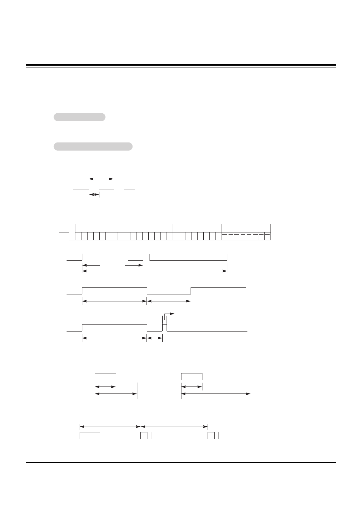
G Output waveform
Single pulse, modulated with 37.917KHz signal at 455KHz
G Configuration of frame
G Repeat code
G Lead code
• 1st frame
Low
custom code
Lead
code
High
custom code
Data code
Data code
T
C
Tf
T1
C0
Carrier frequency
F
CAR = 1/TC = fOSC/12
Duty ratio = T1/T
C = 1/3
• Repeat frame
C1 C2 C3 C4 C5 C6 C7 C0 C1 C2 C3 C4 C5 C6 C7 D0 D1 D2 D3 D4 D5 D6 D7 D0 D1 D2 D3 D4 D5 D6 D7
Repeat code
9 ms 4.5 ms
0.55 ms
9 ms
2.25 ms
G Bit description
G Frame interval : Tf
The waveform is transmitted as long as a key is depressed.
• Bit “0”
Tf Tf
Tf=108ms @455KHz
0.56 ms 0.56 ms
1.12 ms
• Bit “1”
2.24 ms
How to Connect
How to Connect
Remote Control IR Code
Remote Control IR Code
IR Code Information
IR Code Information
http://www.wjel.net

- 15 -
IR CODE
UP (D)
DOWN (
E
)
VOL+ (
G)
VOL- (
F)
POWER On/Off
POWER ON
POWER OFF
MUTE
Number Key 0
Number Key 1
Number Key 2
Number Key 3
Number Key 4
Number Key 5
Number Key 6
Number Key 7
Number Key 8
Number Key 9
AII INPUT SELECT
RGB
DVI
VIDEO
S-VIDEO
COMPONENT
SLEEP
OK (
ç)
MENU
DASP
APC
PIP
PIP INPUT
SWAP
PIP ARC
TWIN PICTURE
ZOOM +
ZOOM Window Size
Window Position
Split Zoom
ARC
ARC (4:3)
ARC (16:9)
ARC (ZOOM)
Auto configure
00H
01H
02H
03H
08H
C4H
C5H
09H
10H
11H
12H
13H
14H
15H
16H
17H
18H
19H
0BH
D5H
C6H
5AH
D8H
BFH
0EH
44H
43H
52H
4DH
60H
61H
63H
64H
6BH
40H
41H
69H
6AH
7BH
79H
76H
77H
AFH
99H
R/C Button
R/C Button
R/C Button
R/C Button
R/C Button (Power On/Off)
Discrete IR Code (Only Power On)
Discrete IR Code (Only Power Off)
R/C Button
R/C Button
R/C Button
R/C Button
R/C Button
R/C Button
R/C Button
R/C Button
R/C Button
R/C Button
R/C Button
R/C Button (RGB/DVI/V-deo/S-video/Component)
Discrete IR Code (Input RGB Selection)
Discrete IR Code (Input DVI Selection)
Discrete IR Code (Input Video Selection)
Discrete IR Code (Input S-video Selection)
Discrete IR Code (Input Component Selection)
R/C Button
R/C Button
R/C Button
R/C Button
R/C Button
R/C Button
R/C Button
R/C Button (PIP/TWIN Exchange)
R/C Button (4:3/16:9)
R/C Button
R/C Button
R/C Button
R/C Button
R/C Button
R/C Button
R/C Button(4:3/16:9/Zoom Mode Selection)
Discrete IR Code (Only 4:3 mode)
Discrete IR Code (Only 16:9 mode)
Discrete IR Code (Only ZOOM mode)
Discrete IR Code (Only RGB-PC mode)
Code (Hexa) Function Note
http://www.wjel.net
 Loading...