

LG MU-60PZ30V-AALZKZ Owner’s Manual

Instullution end Operuting Guide
Model Numbers I P60W38, P60W38H I PLASMA DISPLAY PANEL
]
£ [bpyF ght 2@[}3, ZeI@h Eect (_Hzs C_ tp _,_@t_m
zenith

Warning
s
rnIn
WARNING
WARNING"
TO REDUCE THE RISK OF ELECTRIC SHOCK DO NOT REMOVE COVER (OR BACK) NO USER
SERVICEABLE PARTS _NSIDE. REFER TO QUALIFIED SERVICE PERSONNEL.
the presence of uninsu_ated dangerous voltage" w_bin tile product's enclosure that may be of suffi-
The lightning flash with arrowhead symbol, within an equilateral triangle is intended to alert the user to
cient magn_ude to const_ate a risk of et_ric shock to persons.
The exclamation poinl within an equi_atera{ tfi_gle is intended to alert the user to the presence of
important operating and maintenance (servicing) instructions in the literature eccomp_ying the appli-
ance
WARNING
TO PREVENT FiRE OR SHOCK HAZARDS, DO NOT EXPOSE THIS PRODUCT TO RAIN OR MOISTURE.
FCC NOTICE
• A Class B digital device
This equipment has been tested and found to comply with the iimits for a Class B digital device, pursuant to Part
15 of the FCC Ru_es. These limits are designed to provide reasonable protect:ion against harmful interference in
a residential installation. This equipme_ generates, uses and can radiate radio frequency energy and, if not
inc4alled and used in accordance with the instructions, may cause harmfu_ interference to radio communications.
However, tllere is no guarantee that interference will not occur in a particular installation, if this equipment does
cause harmful interference to radio or television reception, whid-_ can be determin_ by turning the equipment off
and on the user is encouraged to try to correct the interference by one or more of the following measures:
- Reorient or relocate the receiving antenna
- _ncrease the separation between the equipment and receiver.
- Conned the equipment into an outlet on a circuit different from that to which the receiver is connected.
- Consult the dealer or an experienced radio/TV technician for help
• Any changes or modifications not expressly approved by the party responsible for compli-
ance could void the user's authority to operate the equipment.
CAUTION:
Do not attempt to modify tills product in any way w_hout written m,_horiz_ion from Zenith Electronics
Corporation, Unauthorized modification could void the user's aut:hor_y to operate this product
COMPLIANCE:
The responsible party for this product's compliance is:
Zenith Electronics Corporation
2000 MiHbrook Drive
Lincolnshire, II 60069 USA
Phone: 1-_7-941 8_0
WARNING
TO REDUCE THE RISK OF FIRE AND ELECTRIC SHOCK, DO NOT EXPOSE THIS PRODUCT TO
RAIN OR MOISTURE
2 Pl_ma Display
SafetyInstructions
F
important safeguards for you and your new product
"four product has been manufactured and tested with your safety in mind However, improper use can result in potential eiec _
trical shock or fire hazards, To avoid defeating the safeguards that have been built into your new product please read and
observe the following safety points when instaJling and using your new product, and save them for future reference
Observing time simple precautions discussed in this manual can help, you get the many years of enjoyment and safe opera-
tien that are built into your new product.
This product complies with all applicable U.S, Federal safety requirements, and those of the Canadian Standards Association.
1, Read Instructions
All the safety and operating instructions should be read
before the product is operated
2. Follow Instructions
All operating and use instructions should be foimowed,
3, Retain instructions
The safety and operating instructions should be retained for
future reference.
4, Heed Warnings
A_Iwarnings on the product and in the operating instructions
should be adhered to.
5, Cleaning
UnpEug this product from the wall outlet before denning. Do
not use liquid c_eaners or aerosol c_eaners Use a _mp
cloth for denning.
& Water and Moisture
Do not use this preduct near water, for exampte, near a bath
tub wash bowf kitchen sink or laundry tub in a wet base-
merit or near a swimming poet.
7, Accessories, Carts, and Stands
Do not place this preduct on a slippery or fitted surface, or on
an unstable cad, stand, tripod, bracket, or table. Tl_e product
may slide or fuji, causing ser_oas injury to a child or aduff,
and serious damage to the product Use only with a cart,
stud triped, bracket or table recommended by the manu
facturer, or sold with the product. Any mounting of the prod-
uct should fotlow time manufacturer's instructions, and should
use a mounting accessory recommended by the manufac-
turer.
8, Trans_rting Product
A product and cart combination should be moved with care.
Quick stops, excessive force, and uneven surfaces may
cause the product and cart cembin_ion to overturn.
9. Attachments
Do not use attachments not recommended by the product
manufacturer as they may cause hazards.
10, Ventilation
Slots and openings in the cabinet are provi_d for ventilation
and to ensure reliable operation of the product and to protect
it from overheating, and these openings must not be blocked
or covered The openings should never be blocked by plac-
ing the product on a bed, sofa, rug, or other similar surface.
_is product sboutd not be placed in a buiitoin installation
suclm as a bookcase or rack unless proper ventimation is pro-
vided or the manufacturer's instructions have been adl_ered
to_
11. Power Sources
This product should be operated only from the type of power
source indicated on the marking I_el. If you are not sure of
the type of power supply to your home consult your product
dealer or _ocal power company. For products i_ended to
operate from b_ery power, or other sources, refer to the
operating instructions
12. Power-Cord Polarization
This product is equipped with a three-wire grounding type
plug, a plug having a third (grounding) pin. This plug will onty
fit into the grounding-type power outlet. This is a safety fea-
ture. If you are unable to insert the plug into the outlet, con-
tact your electrici_ to replace your obsolete outlet Do not
defeat the safety purpese of time grounding4ype p_ug.
13. Power-Cord Protection
Power-supply cords should be routed so that they are not
likely to be walked on or pinched by items placed upon or
against tbem_ paying particular attention to cords at plugs
convenience receptacles, and the point: where they exit from
the product
POR_,'kBL E CART WARN iN G
Owner*s Manua/ 3
Safety Instructions
Instructions continued
14. Outdoor Antenna Grounding
if an outside antenna or cable system is connected to the
product, be sure the antenna or cable system is grounded so
as to provide some protection against voltage surges and
built-up static charges. Adic[e 810 of the Nationa_ Electrical
Code (U.S.A.), ANSI/ NFPA 70 provides information with
regard to proper grounding of the mast and supporting struc-
ture, grounding of the _ead-in wire to an antenna discharge
unit size of grounding conductors, _ocation of antenna-dis-
charge unit connection to grounding electrodes, and
requirements for the grounding electrode.
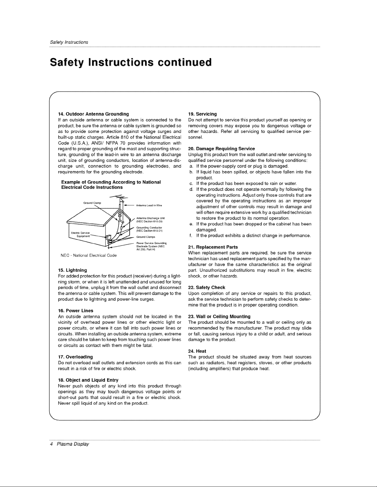
Example of Grounding According to National
Electrical Code Instructions
Gr_'_r_JC_mp
G_ur_ ¢_mp_
P_er Oe_e _eundi_
NEC - Nat onat E_ectrica_Code
15. Lightning
For added protection for this product (receive0 during a light-
ning storm, or when it is left unattended and unused for long
periods of time, unpfug it from the wall outlet and di_onnect
the antenna or cable system. This wilt prevent damage to the
product due to lightning and power-line surges.
16, Power Lin_
An outside antenna system sl_ould not be located in the
vicinity of oved_ead power lines or other electric light or
power circuits, or where it can faJ_ into such power lines or
circuits, When installing an outside antenna system, extreme
care should be taken to keep from touching such power lines
or circuits as contact with them might be fatal,
17. Overloading
Do not overload wall outiets and extension cords as this can
result in a risk of fire or el_fic shock.
Art 2_e P_ H)
19, _rvicing
Do not attempt to service this product yourseff as opening or
removing covers may expose you to dangerous voltage or
other hazards. Refer aH servicing to qualified service per °
sonneL
20, Damage Requiring Service
Unplug this product from the wal_ outlet and refer servicing to
qualified service pe_onne_ under the fo_owing conditions:
a, tf the power°supply cord or plug is damaged,
b. tf liquid has been spi_ied, or objects have fallen into the
product,
c ifthe product has been exposed to rainor ware[,
d_ tf the product does not operate normally by following the
operating instructions. Adjust only those controls that are
covered by the operating instructions as an improper
adjustment of other controls may result in damage and
wi_[ often require extensive work by a qualified technician
to restore the product to its norma_ o_ration.
e, if the product has been droppod or the cabinet has been
damaged.
f. If the product exhibits a distinct change in performance
21, Repl_ement Parts
When replacement parts are required, be sure the _rvice
technician has us_ replacement parts specified by the man°
utacturer or have the same characteristics as the original
part. Unauthorized substitutions may result in fire, electric
shock, or other hazards,
22, Safety Check
Upon completion of any _wice or repairs to this product,
ask the service technician to perform safety checks to deter-
mine that the product is in proper operating condition
23. Wall or Ceiling Mounting
The product shouid be mounted to a wa]_ or ceiling only as
recommended by the manufacturer. The product may slide
or fall, causing sedous iniury to a cl_ild or adu_, and serious
damage to the product.
24. Heat
The product should be situa4ed away from heat sources
such as radiators heat registers,, stoves,, or other products
(including amplifiers) that produce heat.
18. Object and Liquid Entry
Never push objects of any kind into this product through
openings as they may touch dangerous voltage points or
short-out parts that could result in a fire or electric shock
Never spill liquid of any kind on the product.
4 Plasma Display
Conten_s
Warnings ...................................... 2
Safety Instructions ............................ 3.°4
introduction
Controls _d Connection Options ........... 7
Remote Control Key Functions ............... 8
Installation
InstallationInstructions.................. 9_I0
Externa_ Equipment Connections .......... 11 --14
VCR Setup ....................... 11
Cabte TV Setup ........................ 11
External/VV Source Setup .................. 12
DVD Setup ............................... 12
DTV Setup ........................ 12
PC Setup ............................ 13-_14
Operation
Turning on time Monitor ................. 15
Menu Language Selection ................... 15
Video Menu Options
APC (Auto Picture Control) .......... 16
Manual Picture Control ............... 16
Aulo Color Temperature Controt .......... 16
Manual Color Temperature Control .......... 16
Audio Menu Options
DASP (Digital Auto Sound Processing) ...... 17
Manual Sound Control .............. 17
AVL (Auto Volume Leveler) ................ 17
Time Menu Options
Clock setup ........................... 18
On/Off Timer Setup ..................... 18
Auto Off ............................. 18
Sleep Timer ........................... 18
Special Menu Options
Key Lock ................................ 19
ISM Method ............................ 19
Low power ............................ 19
Menu Rotation For Vertica_ Viewing ............ 19
Screen Menu Options
Auto Adjustment ........................ 20
SettingPictureFormat ................. 20
Picture Size Zoom ...................... 20
SpI_ Zoom .............................. 21
_reen Position ........................ 21
Manual Configure .............. 21
_reen Adjustmems ........................ 22
Initializing.............................. 22
Selecting Wide VGA/XGA mode ............. 22
Luminance Noise Reduction .............. 22
PIP (Picture-in-Picture)Fe_ure
Watching PIP ............................. 23
PIP Size ................................. 23
PIP Aspect Ratio ....................... 23
Swapping PIP ........................... 23
Moving PIP ............................. 23
selecting an input Signa_ Source for P_P ...... 23
Twin Picture Setup Options
Watching Twin Picture .............. 24
Sub Picture Size Adjustment ............... 24
Swapping the Twin Picture ................. 24
Selecting a Source for the Twin Picture ....... 24
External Control Device Setup ................ 25_30
IR Code Information ...................... 31o-32
Troubleshooting Checklist ...................... 33
Maintenance ................................. 34
Specifications .................................. 34
Your' Zenith Limited Warranty ................... 35~36
Setup and Operation Checklist
Setup and Operation Ch_klist
(See pages 11~13 for available connection and operational setup options)
1. Unpack Monitor and aH acc_s_ries,
2. Connect all external video and audio equipment,
see pages 11 '_13
3 install b_eries in remote control
See page 8,
4 Turn Monitor on.
See page 15
After reading this manual keep it handy for future reference,
5. Turn video source equipment on.
6. Select viewing source for Monitor.
see page 8.
7. Fine-tune source image and _und to personal preference
or as required by source,
See pages 16 _ 17.
8. Additional features Setup
see Contents above.
Owner's Manual 5
Introduction
What is a Plasma Display Panel (PDP)?
If voltage is applied to gas w_thinglass panels ultraviolet rays are produced and fused with a fluorescent substance At that
instant, _ightis emitted A P{asma Display is a next generation fiat Display using this phenomenon.
160 ° - Wide angle range of vision
Your featpane_plasma screen offers an exceptionally broad viewing angle _-over 160 degrees, This means that the display is
clear and visible to viewers who can see the screen anywhere in the room
Wide Screen
The screen of tl_e Plasma DispUayis 60" so wide that your viewing experience is as if you are in a theater_
Multimedia
Connect your plasma display to a PC and you can use it for conferencing games, and intemet browsing The Pictureqn-Picture
feature atlows you to view your PC and video images simultaneously.
Versatile
The tighl weight and thin size makes it easy to instaliyour ptasma display in a variety of tocations where conventiona_ TVs woutd
notfit
The PDP Manufacturing Process: Why minute colored dots may be present on the PDP screen
The PDP (Piasma Display Panel) which is the display device of this product is composed of 0.9 to 2,2 million ceils. A few cell
defects will normatly occur in the PDP manufacturing process, Severa_ minute colored dots visible on the screen shouid be accept-
able. This also occurs in other PDP manufacturers' products and the tiny dots appearing does not mean that this PDP is defective.
Thus a few ceil defects are not sufficient cause for the PDP to be exchanged or returned Our production technogogy is designed
to minimize cett defects dunng the manufacture and operation of this product
Cooling Fan Noise
In the same way that a fan is used in a PC computer to keep the CPU (Central Processing Unit) cool the PDP is equipped w_h
cooling fans to cool the Monitor and improve its reHabil_y. Therefore, a certain leve_ of noise could occur wNe the fans are operat-
ing and cooming the PDP.
The fan noise _esn3 have any negative effect on the PDP's efficiency or reliability, The noise from these fans is normal dudng the
operation of this produ_, We hope you understand that a certain leve_ of noise from the cooling fans is acceptable and is not suffi-
cient cause for the PDP to be exchanged or returned.
6 Pl_ma Display
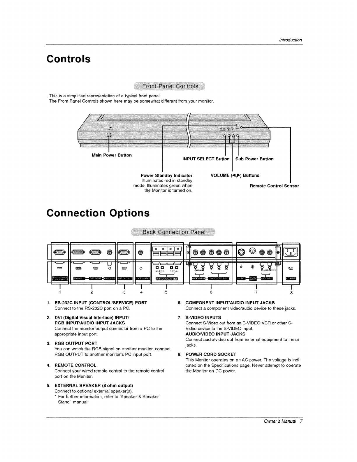
This is a simplified representation of a typica_ front pane_
The Front Pane_ Controls shown here may be somewhat different from your monitor_
introduction
Main Power Button
Power Standby indicator
illuminates red in standby
mode [Huminates green when
the Monitor is turned on.
Connection Options
@@@@
oli,
1¸
I I I
2 3 4
RS-2320 INPUT (CONTROL/SERVICE) PORT
Connect to the RS-232C port on a PC_
2.
DVI (Digital Visual interface) INPUT/
RGB INPUT/AUDIO INPUT JACKS
Connect the mon_or output connector from a PC to the
appropriate input port.
RGB OUTPUT PORT
3_
You can watch the RG8 signat on another monitor, connect
RGB OUTPUT _o another monitor's PC input port,
4_
REMOTE CONTROL
Connect: your wired remote control to the remote cor_rol
port on the Monitor,
5,
EXTERNAL SPEAKER (8 ohm output)
Conn_ to optiona{ extema_ speaker(s),
* For further information, refer to 'Speaker & Speaker
Stand' manua_
INPUT SELECT Button Sub Power Btrtton
VOLUME (<1,1_) Buttons
Remote Control Sensor
ma ae o o g £ £ I I @ &o r
I I I
5 6 7
6,
C_PONENT INPUT/AUDIO INPUT JACKS
Conned a component video/audio device to these j_ack&
7.
S-VIDEO INPUTS
Connect S-Video out from an S VIDEO VCR or other S-
Video device to the S-ViDEO input,
AUOIO/VIDEO INPUT JACKS
Connect audio/video out from externat equipment to these
jacks,
8_
POWER CORD SOCKET
This Monitor operates on an AC power The voyage is indi o
cat_ on the Specifications page Never attempt to operate
the Monitor on DC power.
ma[
Owner's Manual 7
Introduction
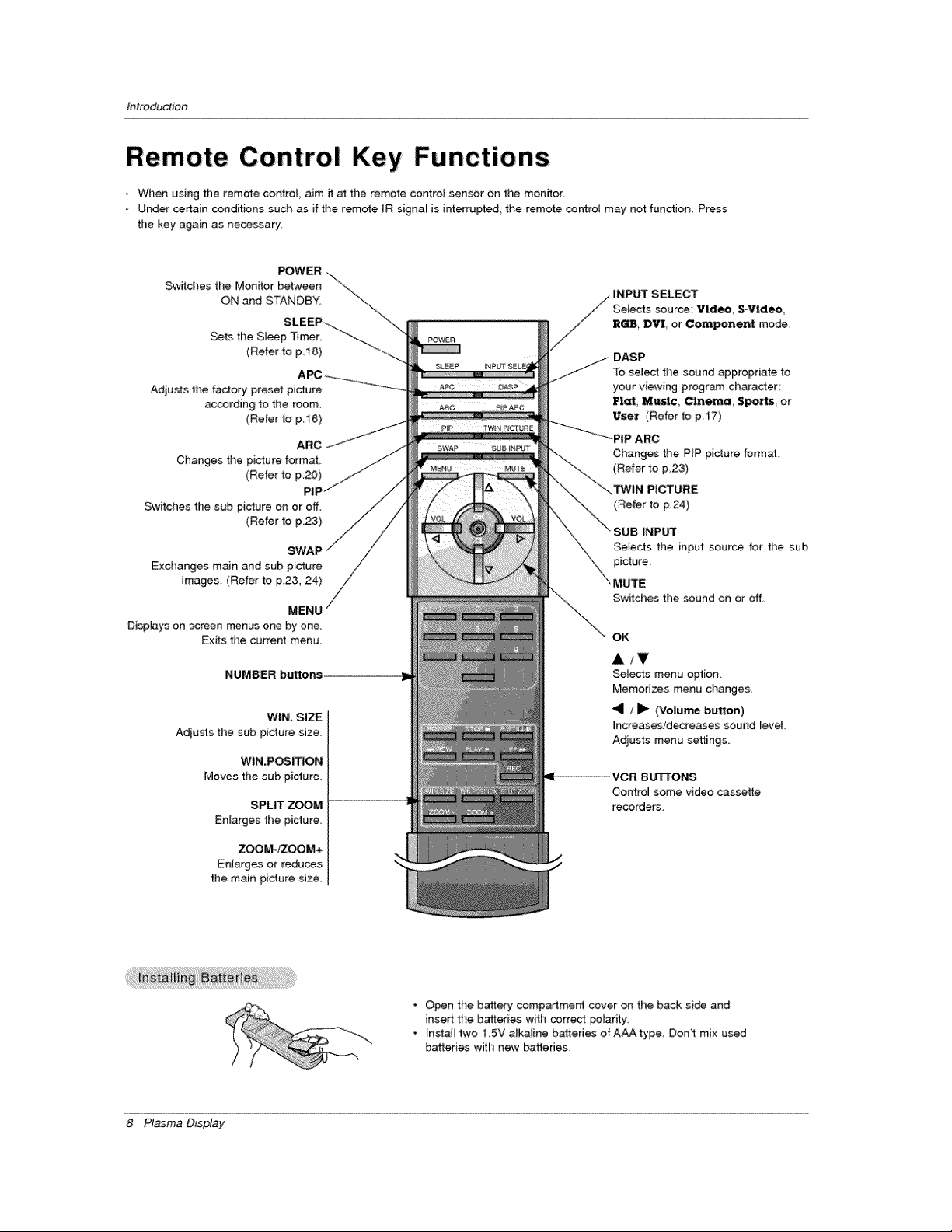
Remote Control Key Functions
When using the remote corCtroL aim it at the remote control sensor on the monitor
Under certain conditions such as if the remote IR signal is interrupted, the remo_e controt may not function, Press
the key again as necessary
Switches the Monitor between "\
POWER ....
ON and STANDBY, "_..
SLEEP_-_ .... \-\
Sets the S_eep _mer _-_
(Refer to p 18) -_--.._
Adju_s the factory preset picture
according to the room.
(Refer to p 16)
ARC
Changes the picture format
(Refer to p.20)
PIF
Switches the stJb pi_ure on or off.
(Refer to p,23)
SWAP
Exchanges m_n and sub picture
images. (Refer to F23, 24)
MENU
Disp[ays on screen menus one by one.
Exits the current menu
NUMBER buttons
WIN, SIZE
Adjusts thesab picture size,
WIN.POSI_ON
Moves the sub picture.
SPLIT ZOOM
Enlarges the picture.
ZOOM-_OOM+
Enlarges or reduces
the main picture size.
DASP
To select the sound _propriate to
your viewing program character:
Flat, Music, Cinema, Spo-_, or
User (Refer to p17)
--'_'_....... _PIP ARC
Changes the PiP picture format
(Refer to p,23)
(Refer to p,24)
INP_
Selects the input source for the sub
picture.
MUTE
/
Switches the sound on or off.
OK
A/T
_te,cts menu option
Memorizes menu changes,
<1 / _1_ (Volu_ button)
increases/decreases sound level,
Adjusts menu settings
ICR BU'B'ONS
Control some video cassette
recorders.
8 Pl_ma Display
• Open the battery compartment cover on the back side and
insert the batteries with correct poiarity.
• Instal_ two 1 5V alkaline batteries of AAA type Don't mix used
batteries with new batteries.
tnstaltation
t
IOn
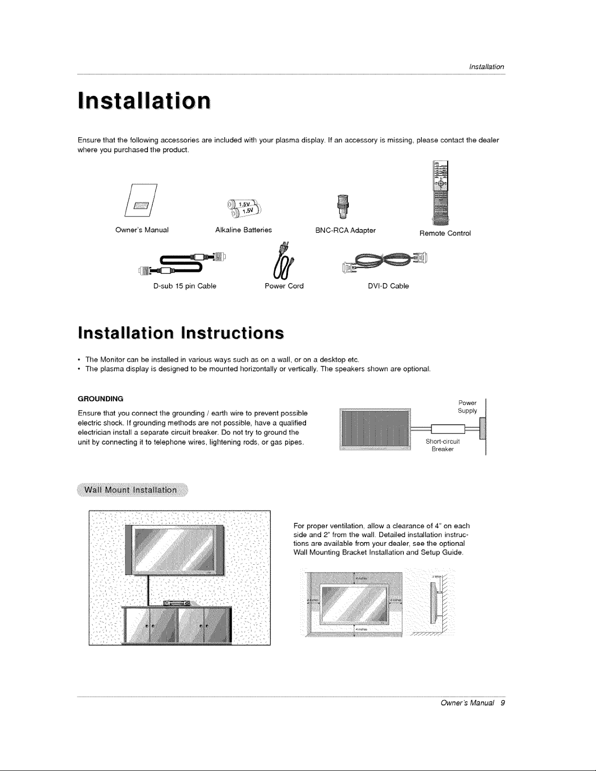
Ensure that the following accessories are inc[u_d with your plasma display If an accessory is m[ssing_ please contact the dealer
where you purchased the product,
Owners Manual A_kaline Bakeries BNC-RCA Adapter Remote Control
D_sub 15 pin Cable Power Cord DVFD Cable
* The Monitor can be installed in various ways such as on a wall, or on a desktop etc
- The plasma display is designed to be mourned horizo_l[y or verticam_y, The speakers shown are optional
GROUNDING
Ensure that you connect tl)e grounding / earth wire to prevent possiMe
e{ectric shock, If grounding methods are not possib{e, have a qualified
electrician insta_[ a serrate circuit breaker Do not try to ground the
unit by connecting it to telephone wires lightening rods or gas pipes
i:i i ii
For proper ventilation allow a clearance of 4' on each
side and 2_ from the wa& Detailed installation instruc
tions are available from your dealer, see the optional
Wail Mounting 8r,acket Installation and Setup Guide
Power
Supply
Sho_l-circuit
Breaker
Owner's Manual 9
Installa tie n
Installation Instructions continued
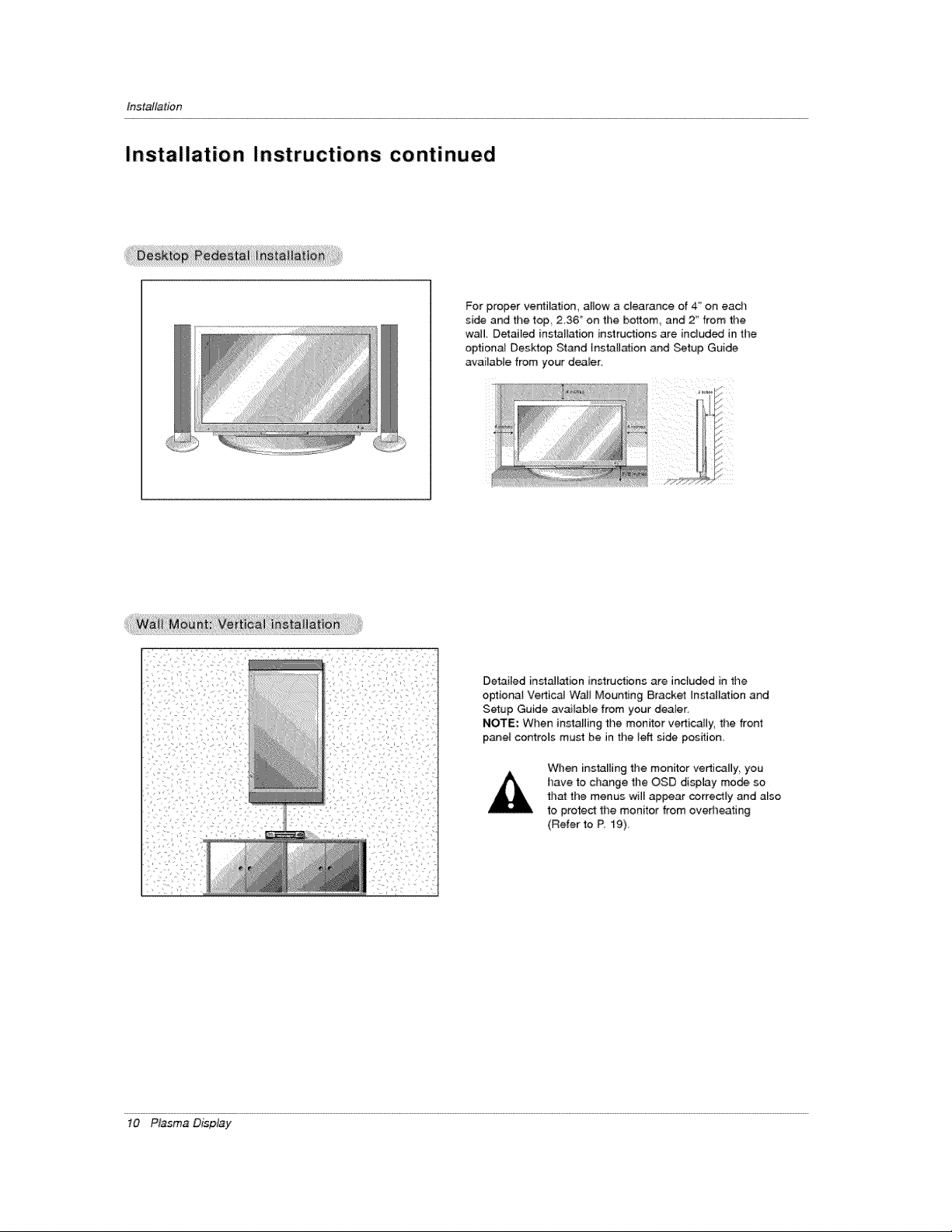
For proper ventilation, allow a clearance of 4" on ead_
side and the top 2,36 '_on the bottom and 2 _'from time
wail Detailed installation instructions are indud_ in the
optional Deskfop Stand lnsta[i_ion and Setup Guide
available from your dealer,
/I)
[/
_i'!i'!;i;_i;i;w__t_iii;ii_M;!_i_iiti!;!iii!!V!_i!il_!i!;_;!!_;_;;ii!;_!i!_i_i;is!i_;_i!i;_iii i;_i;iiiiiiiiii;;!i!i!ii!ii!ilil;iiiii;ii;:_:
Detailed installation instructions are inc}uded in the
optiona_ Vertical WaJJMounting Bracket Installation and
Setup Guide available from your dearer.
NOTE; When installing the monitor verticaJ[y, the front
p_el controls must be in the lefl side position.
When installing the monitor vertically, you
have to change the OSD display mode so
that the menus will appear correctly and also
to proteCt the monitor from overheating
(Refer to R 19)_
10 Plasma Display
Installation
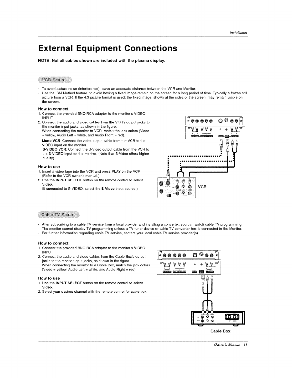
External Equipment Connections
NOTE: Not all cables shown are included with the p|asma display:
- To avoid picture noise (interference) _eave an adequate distance between the VCR and Monitor
Use the ISM Method feature to avoid having a fixed image remain on the screen for a tong period of time. Typically a frozen still
picture from a VCR If time 4:3 picture format is used the fixed image., shown at the sides of the screen, may remain visible on
the screen.
How to connect
1. Connect the provided BNC_RCA adapter to the monitor's VIDEO
iNPUT.
2 Connect the audio and video cables from the VCR's output iacks to
the monitor input iacks, as shown in the figure
When connecting the monitor to VCR, match the jack colors (Video
= ye{_ow, Audio Left = white, and Audio RigI_ = red).
Mono VCR: Connect the video output cable from the VCR to the
VIDEO input on the monitor.
S-VIDEO VCR: Connect the SWideo output cable from the VCR to
the SoWDEO inp_rt on the monitor. (Note that S-Video offers higher
quality)
How to use
1 insert a video tahoe into the VCR and press PLAY on the VCR
(Refer to the VCR owner's manuaL)
2. Use the iNPUT SELECT button on time remote cor4rol to select
Video,
(if connected to S-VIDEO, select the S-Vid_ input source.)
- After subscribing to a cable TV service from a _ocal provider and instal{ing a conveder, you can watch cable TV programming.
The monitor cannot display TV programming unless a TV tuner device or cable TV converter box is connected to the Monitor.
For further information regarding cabie TV service, c_ntact your local cable TV service provider(s).
How to connect
1. Connect the provided BNC°RCA adapter to the monitor's VIDEO
iNPUT
2 Connect the audio and video cables from the CaNe Boxes output
jacks to the monitor input jacks, as shown in the figure
When connecting the monitor to a Cable Box match the jack colors
(Video = yellow, Audio Left = white, and Audio Righ_ = red).
How to use
1. Use the INPUT SELECT button on the remote control to select
Video
2. Select your desired channel with the remote control for cable box_
Cable Box
Owner _ Manual 11
 Loading...