


LG ARNU 243 S8R2, ARNU 073 SBL4, ARNU 093 SER2, ARNU 053 SBL4, ARNU 093 SBL4 Engineering Manual
...
EM-MultiV-WallMounted-IndoorUnits-01-15
WALL-MOUNTED INDOOR UNIT
ENGINEERING MANUAL
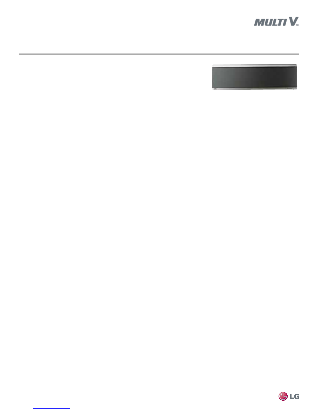
Art Cool™ Mirror Wall-Mounted
7,500 to 24,200 Btu/h
Standard Wall-Mounted
5,500 to 24,200 Btu/h

PROPRIETARY DATA NOTICE
This document, as well as all reports, illustrations, data, information,
and other materials are the property of LG Electronics U.S.A., Inc., and are
disclosed by LG Electronics U.S.A., Inc. only in confidence.
This document is for design purposes only.
A summary list of safety precautions is on page 3.
For more technical materials such as submittals, catalogs, installation,
owner’s, and service manuals, visit www.lghvac.com.
For continual product development, LG Electronics U.S.A., Inc. reserves the right to change specifications without notice.
© LG Electronics U.S.A., Inc.
TABLE OF CONTENTS
DANGER
CAUTION
Unit Nomenclature ................................................................................. 4
Indoor Unit Overview ............................................................................ 5
Controllers Overview ............................................................................ 8
LATS Overview .................................................................................... 14
Art Cool™ Mirror Wall-Mounted Indoor Units .............................. 15-32
Mechanical Specications ................................................................. 16
General Data ..................................................................................... 17
Electrical Data ................................................................................... 18
External Dimensions ..................................................................... 19-20
Electrical Wiring Diagrams ........................................................... 21-22
Refrigerant Flow Diagrams ................................................................ 23
Acoustic Data ............................................................................... 24-25
Air Velocity / Temperature Distribution .......................................... 26-28
Capacity Tables ............................................................................ 29-32
Standard Wall-Mounted Indoor Units ...........................................33-54
Mechanical Specications ................................................................. 34
General Data ................................................................................ 35-36
Electrical Data ................................................................................... 37
External Dimensions ..................................................................... 38-39
Electrical Wiring Diagrams ................................................................ 40
Refrigerant Flow Diagrams ................................................................ 41
Acoustic Data ............................................................................... 42-45
Air Velocity / Temperature Distribution .......................................... 46-49
Capacity Tables ............................................................................ 50-54
Application Guidelines ................................................................... 55-60
Selecting the Best Location ............................................................... 56
General Mounting .............................................................................. 56
General Drain Piping Information ................................................. 57-58
Wiring Guidelines ......................................................................... 59-60
Wired Remote Controller Location .................................................... 60
Acronyms ............................................................................................. 61
Introduction
TABLE OF SYMBOLS
This symbol indicates an imminently hazardous situation which, if not avoided, will result in death or serious injury.
This symbol indicates a potentially hazardous situation which, if not avoided, could result in death or serious injury.
This symbol indicates a potentially hazardous situation which, if not avoided, may result in minor or moderate injury.
This symbol indicates situations that may result in equipment or property damage accidents only.
This symbol indicates an action should not be completed.
Due to our policy of continuous product innovation, some specications may change without notication.
LG Electr onics U.S.A., Inc., Engl ewood Cliffs , NJ. All rights re served. “LG” is a r egistered tra demark of LG Corp.
©
INTRODUCTION | 3
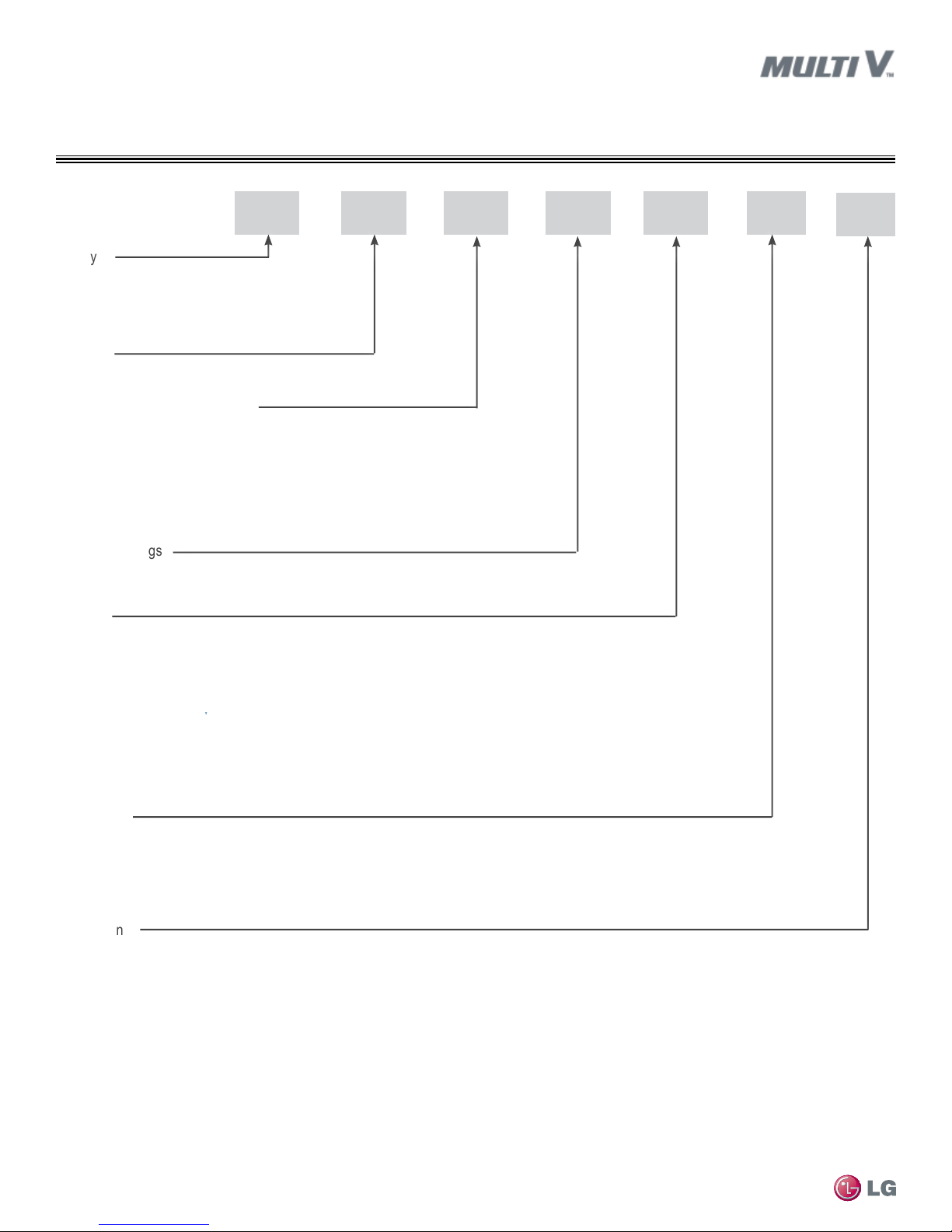
UNIT NOMENCLATURE
ARN U 07 3 TN C
Family
ARN = Multi V Indoor Unit
(Refrigerant R410A)
Type
U = DC Inverter Heat Pump
Indoor Unit Nominal Capacity
05 = 5,000 Btu/h
07 = 7,000 Btu/h
09 = 9,000 Btu/h
12 = 12,000 Btu/h
15 = 15,000 Btu/h
Electrical Ratings
3 = 208–230V/60Hz/1Ph
Model
B3 = Ducted (low static - bottom return)
B4 = Ducted (low static - bottom return)
B8 = Ducted (high static)
BG = Ducted (high static)
BR = Ducted (high static)
CE = Floor Standing (small frame)
CF = Floor Standing (large frame)
L1 = Ducted (low static)
L2 = Ducted (low static)
L3 = Ducted (low static)
18 = 18,000 Btu/h
24 = 24,000 Btu/h
28 = 28,000 Btu/h
30 = 30,000 Btu/h
36 = 36,000 Btu/h
42 = 42,000 Btu/h
48 = 48,000 Btu/h
54 = 54,000 Btu/h
76 = 76,000 Btu/h
96 = 96,000 Btu/h
NJ = Vertical/Horizontal Air Handling Unit
NK = Vertical/Horizontal Air Handling Unit
S8 = Wall Mounted/Mirror (large frame)
SE = Wall Mounted/Mirror (small frame)
SB = Standard Wall Mounted
SC = Standard Wall Mounted
TT = 1-Way Ceiling Cassette
TU = 1-Way Ceiling Cassette
TL = 2-Way Ceiling Cassette
TM = 4-Way Ceiling Cassette
4
TN = 4-Way Ceiling Cassette
TP = 4-Way Ceiling Cassette
TQ = 4-Way Ceiling Cassette
TR = 4-Way Ceiling Cassette
VE = Convertible Surface Mounted
VJ = Ceiling Suspended
Feature
A = Basic
C = Plasma Filter
G = Low Static
MULTI V Wall-Mounted Indoor Unit Engineering Manual
L = Neo Plasma
R = Mirror and Neo Plasma
U = Uncased
Generation
2 = Second
4 = Fourth
A = Second, Revision A
Due to our policy of continuous product innovation, some specications may change without notication.
LG Electr onics U.S.A., Inc., Engl ewood Cliffs , NJ. All rights re served. “LG” is a r egistered tra demark of LG Corp.
4 | INTRODUCTION
©
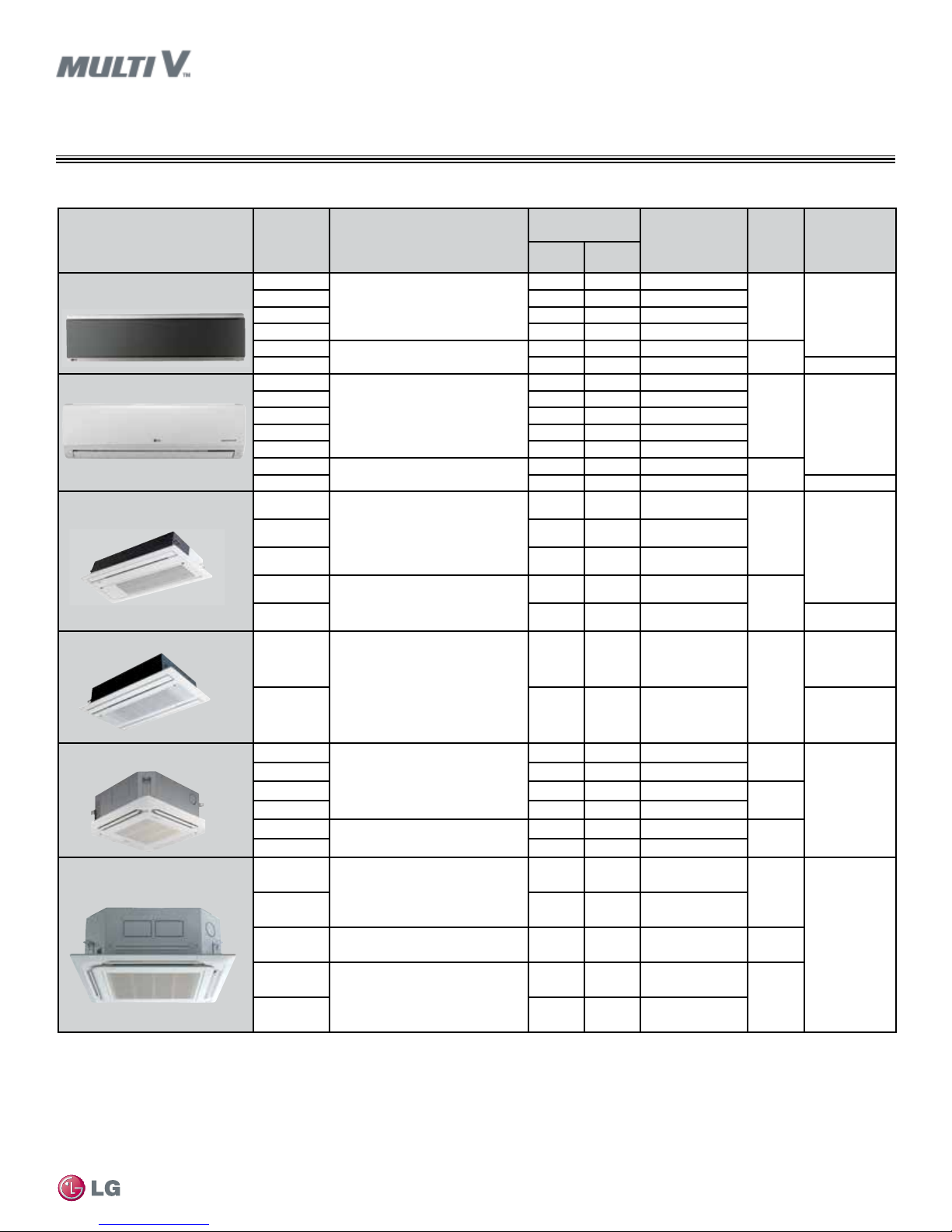
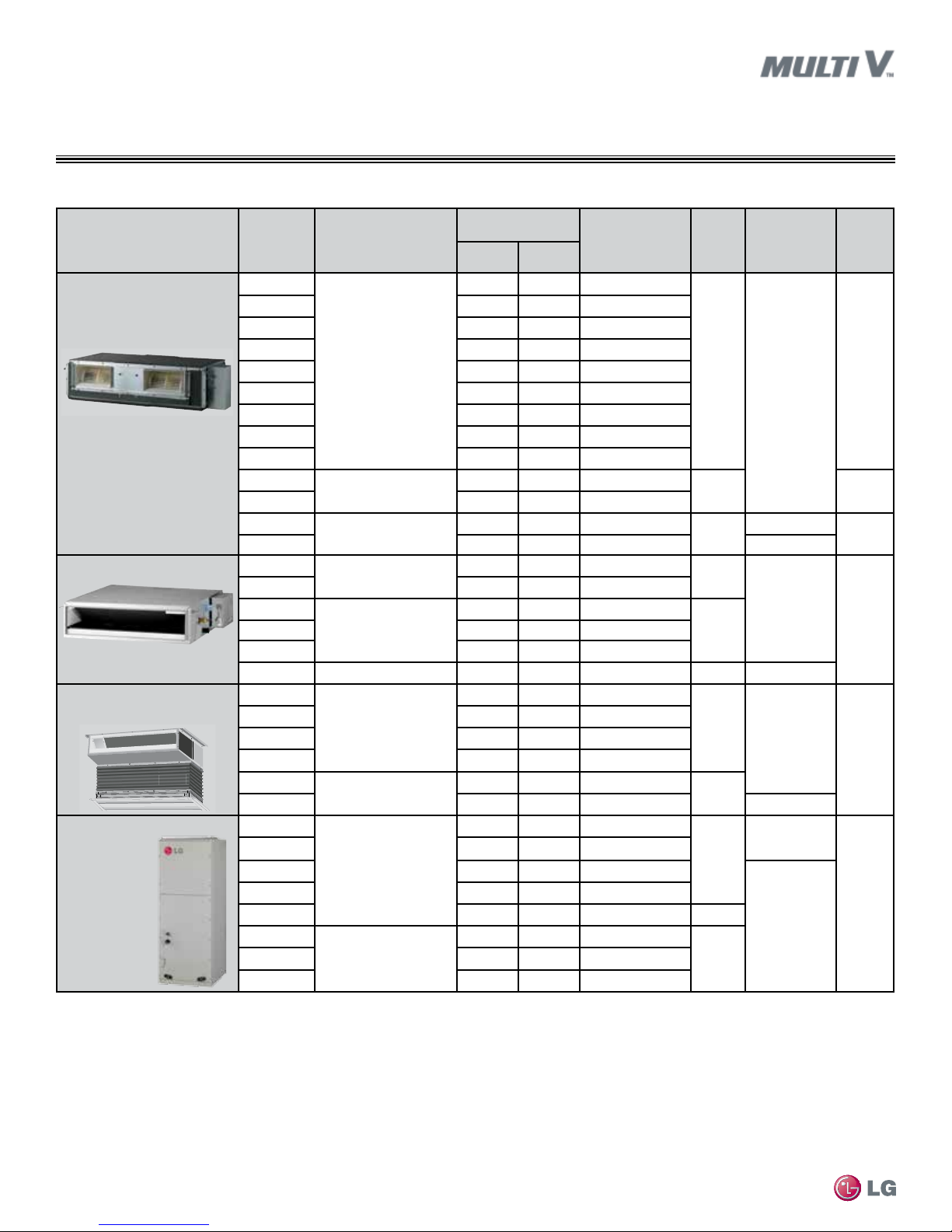
Table 1: Wall-Mounted / Ceiling Cassette Indoor Units.
Unit/Type
1
Wall Mounted–ART COOL
Mirror
TM
ARNU*****
073 SER2
093 SER2 9,600 10,900 282/247/177
2
123 SER2 12,300 13,600 353/283/212
153 SER2 15,400 17,100 371/283/212
183 S8R2
243 S8R2 24,200 27,300 632/508/424 3/8, 5/8
Wall Mounted–Standard
053 SBL4
073 SBL4 7,500 8,500 1,190/1,120/1,050
093 SBL4 9,600 10,900 1,260/1,190/1,050
123 SBL4 12,300 13,600 1,420/1,260/1,120
153 SBL4 15,400 17,100 1,550/1,350/1,190
183 SCL4
243 SCL4 24,200 27,300 1,280/1,140/1,000 3/8, 5/8
Ceiling Cassette–One Way
073 TUC4
093 TUC4 9,600 10,900 325/304/290
Body: 33-7/8 x 17-3/4 x 6-11/16
Panel: 43-5/16 x 19-3/4 x 1-3/8
123 TUC4 12,300 13,600 353/325/290
Dimensions
(W x D x H)
(inches)
36-1/16 x 6-1/2 x 11-1/8
43-9/16 x 7-7/8 x 11-13/16
35-1/4 x 8-15/16 x 11-7/16
40-5/16 x 9-7/8 x 12-13/16
INDOOR UNIT OVERVIEW
Wall-Mounted / Ceiling Cassette
Nominal Capacity
Btu/h
3
Cooling
Heating
Air Flow Rate
(CFM)
3
(H/M/L4)
7,500 8,500 247/212/141
19,100 21,500 508/459/388
5,500 6,100 1,120/1,080/1,050
19,100 21,500 1,120/1,050/980
7,500 8,500 290/258/226
Weight
(lbs.)
25
34
22
31
Body: 33
Panel: 10
Pipe
Connections
(inches, O.D.)
(Liquid, Vapor)
1/4, 1/2
1/4, 1/2
1/4, 1/2
Introduction
183 TTC4
243 TTC4 24,200 24,200 515/470/406 3/8, 5/8
Body: 46-1/2 x 17-3/4 x 6-7/8
Panel: 55-15/16 x 19-3/4 x 1-3/8
Ceiling Cassette–Two Way
183 TLC4
Body: 32-11/16 x 21-5/8 x 8-7/8
Panel: 41-5/16 x 25-3/16 x 1-5/8
243 TLC4 24,200 27,300 601/530/459 3/8, 5/8
Ceiling Cassette–Four Way
(2' x 2')
053 TRC4
073 TRC4 7,500 8,500 265/247/212
093 TRC4 9,600 10,900 283/265/251
Body: 22-7/16 x 22-7/16 x 8-7/16
Panel: 27-9/16 x 27-9/16 x 7/8
123 TRC4 12,300 13,600 307/283/247
153 TQC4
183 TQC4 19,100 21,500 396/388/353
Ceiling Cassette–Four Way
(3' x 3')
243 TPC4
283 TPC4 28,000 31,500 671/565/494
363 TNC4
423 TMC4
483 TMC4 48,100 51,200 1,130/953/883
1
All indoor units require 208–230V/60Hz/1Ph and an AWG18-2 communication cable.
2
Model number shows nominal capacity and frame size designator.
3
Nominal cooling capacity rating obtained with air entering the indoor unit at 80ºF dry bulb (DB) and
67ºF wet bulb (WB) and outdoor ambient conditions of 95ºF dry bulb (DB) and 75ºF wet bulb (WB).
Body: 22-7/16 x 22-7/16 x 10-3/32
Panel: 27-9/16 x 27-9/16 x 7/8
Body: 33-1/16 x 33-1/16 x 8
Panel: 37-3/8 x 37-3/8 x 1-7/16
Body: 33-1/16 x 33-1/16 x 9-5/8
Panel: 37-3/8 x 37-3/8 x 1-7/16
Body: 33-1/16 x 33-1/16 x 11-5/16
Panel: 37-3/8 x 37-3/8 x 1-7/16
19,100 21,500 470/427/385
Body: 42
Panel: 13
19,100 21,500 459/424/353
1/4, 1/2
Body: 49
Panel: 11
5,500 6,100 265/247/212
Body: 29
Panel: 7
15,400 17,100 388/353/328
Body: 32
Panel: 7
Body: 35
1/4, 1/2
Panel: 7
24,200 27,300 600/530/459
Body: 48
Panel: 13
36,200 40,600 883/777/706
42,000 43,800 1,059/918/812
Body: 54
Panel: 13
Body: 59
3/8, 5/8
Panel: 13
Nominal heating capacity rating obtained with air entering the indoor unit at 70ºF dry bulb (DB) and 60°
F wet bulb (WB) and outdoor ambient conditions of 47ºF dry bulb (DB) and 43ºF wet bulb (WB).
4
H/M/L = High/Medium/Low
Due to our policy of continuous product innovation, some specications may change without notication.
LG Electr onics U.S.A., Inc., Engl ewood Cliffs , NJ. All rights re served. “LG” is a r egistered tra demark of LG Corp.
©
INTRODUCTION | 5
INDOOR UNIT OVERVIEW
Ducted
Table 2: Ducted Indoor Units.
Dimensions
(W x D x H)
(inches)
46-1/2 x 17-3/4 x 11-3/4
48-7/16 x 23-3/8 x 15
61-1/2 x 27-1/8 x 18-1/8
27-9/16 x 27-9/16 x 7-1/2
35-7/16 x 27-9/16 x 7-1/2
32-5/8 x 22-5/8 x 7-1/2
43-5/16 x 22-5/8 x 7-1/2
18 x 21-1/4 x 48-11/16
25 x 21-1/4 x 55-3/16
Unit/Type
Ducted High Static
1
ARNU*****
073 BGA4
2
093 BGA4 9,600 10,900 452 / 406 / 332
123 BGA4 12,300 13,600 477 / 427 / 332
153 BGA4 15,400 17,100 487 / 417 / 293
183 BGA4 19,100 21,500 537/487/417
243 BGA4 24,200 27,300 671/537/487
283 BGA4 28,000 31,500 1,130/1,003/961
363 BGA4 36,200 40,600 1,003/894/770
423 BGA4 42,000 43,800 893/770/622
483 BRA4
543 BRA4 54,000 61,400 1,819/1,678/1,395
763 B8A4
963 B8A4 95,900 107,500 2,542/2,260/2,260 3/8, 7/8
Ducted Low Static
073 L1G4
093 L1G4 9,600 10,900 320/250/200
123 L2G4
183 L2G4 19,100 21,500 530/450/360
243 L3G4 43-5/16 x 27-9/16 x 7-1/2 24,000 27,300 710/570/430 60 3/8. 5/8
Ducted Low Static Built In
073 B3G4
093 B3G4 9,600 10,900 318/247/212
123 B3G4 12,300 13,600 353/283/229
153 B3G4 15,400 17,100 388/353/283
183 B4G4
243 B4G4 24,200 27,300 600/530/353 3/8, 5/8
Vertical/Horizontal Air
Handling Unit
MULTI V Wall-Mounted Indoor Unit Engineering Manual
123 NJA4
183 NJA4 18,000 20,000 580/530/480
243 NJA4 24,000 27,000 710/640/480
303 NJA4 30,000 34,000 880/800/630
363 NJA4 36,000 40,000 990/880/800 121
423 NKA4
543 NKA4 54,000 60,000 1,475/1,400/1,260
1
All indoor units require 208–230V/60Hz/1Ph and an AWG18-2 communication cable.
2
Model number shows nominal capacity and frame size designator.
3
Nominal cooling capacity rating obtained with air entering the indoor unit at 80ºF dry bulb (DB) and
67ºF wet bulb (WB) and outdoor ambient conditions of 95ºF dry bulb (DB) and 75ºF wet bulb (WB).
Nominal Capacity
Btu/h
3
Cooling
Heating
Air Flow Rate
3
(CFM)
(H/M/L4)
Weight
(lbs.)
Pipe
Connections
(inches, O.D.)
(Liquid, Vapor)
7,500 8,500 441 / 406 / 332
84
3/8, 5/8
48,100 51,200 1,568/1,395/1,183
76,400 86,000 2,050/1,766/1,766
7,500 8,500 270/230/200
12,300 13,600 360/310/250
112 0.78
192
3/8, 3/4
39
1/4, 1/2
51153 L2G4 15,400 17,100 450/360/310
7,500 8,500 283/229/194
19,100 21,500 494/424/353
12,000 13,500 530/480/380
46
57
1/4, 1/2
1/4, 1/2
117
42,000 46,000 1,250/1,100/1,000
3/8, 5/8
165483 NKA4 48,000 54,000 1,400/1,260/1,000
Nominal heating capacity rating obtained with air entering the indoor unit at 70ºF dry bulb (DB) and 60°
F wet bulb (WB) and outdoor ambient conditions of 47ºF dry bulb (DB) and 43ºF wet bulb (WB).
4
H/M/L = High/Medium/Low
Max.
ESP
(inches)
0.62
0.98
0.19
0.15
1.0
Due to our policy of continuous product innovation, some specications may change without notication.
LG Electr onics U.S.A., Inc., Engl ewood Cliffs , NJ. All rights re served. “LG” is a r egistered tra demark of LG Corp.
6 | INTRODUCTION
©
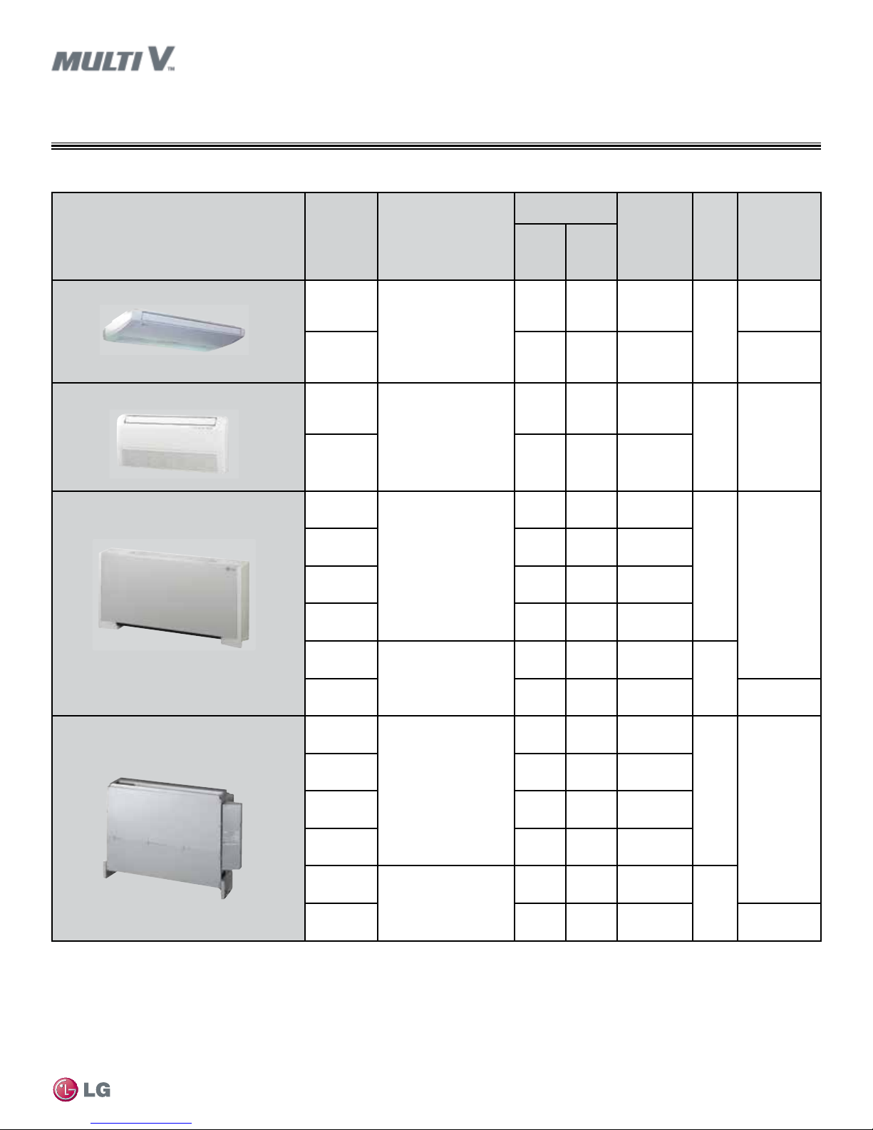
Table 3: Surface Mounted / Floor Standing Indoor Units.
Unit/Type
1
ARNU****
Ceiling Suspended
183VJA2
INDOOR UNIT OVERVIEW
Surface Mounted / Floor Standing
Nominal Capacity
Cooling
Btu/h
3
Heating
2
Dimensions
(W x D x H)
(inches)
19,100 21,500 565/495/424
3
Air Flow
Rate
(CFM)
(H/M/L4)
Weight
(lbs.)
Pipe
Connections
(inches, O.D.)
(Liquid, Vapor)
1/4, 1/2
Convertible Surface Mounted
Floor Standing –Cased
Floor Standing – Uncased
37-7/16 x 8-11/16 x 25-5/8
55
243VJA2 24,200 27,300 636/565/495 3/8, 5/8
093VEA2
35-7/16 x 7-7/8 x 19-5/16
9,600 10,900 268/243/219
31 1/4, 1/2
123VEA2 12,300 13,600 325/268/244
073 CEA4
7,500 8,500 300/265/229
093 CEA4 9,600 10,900 335/300/265
42 x 8 x 25
123 CEA4 12,300 13,600 371/335/300
60
1/4, 1/2
153 CEA4 15,400 17,100 406/353/335
183 CFA4
52-15/16 x 8 x 25
19,100 21,500 565/494/424
75
243 CFA4 24,200 27,300 635/565/494 3/8, 5/8
073 CEU4
7,500 8,500 300/265/229
Introduction
1
All indoor units require 208–230V/60Hz/1Ph and an AWG18-2 communication cable.
2
Model number shows nominal capacity and frame size designator.
3
Nominal cooling capacity rating obtained with air entering the indoor unit at 80ºF dry bulb (DB) and
67ºF wet bulb (WB) and outdoor ambient conditions of 95ºF dry bulb (DB) and 75ºF wet bulb (WB).
Due to our policy of continuous product innovation, some specications may change without notication.
LG Electr onics U.S.A., Inc., Engl ewood Cliffs , NJ. All rights re served. “LG” is a r egistered tra demark of LG Corp.
©
093 CEU4 9,600 10,900 335/300/265
38-1/2 x 7-15/16 x 25-3/16
123 CEU4 12,300 13,600 371/335/300
46
1/4, 1/2
153 CEU4 15,400 17,100 406/353/335
183 CFU4
49-7/16 x 7-1/2 x 25-3/16
19,100 21,500 565/494/424
58
243 CFU4 24,200 27,300 635/565/494 3/8, 5/8
Nominal heating capacity rating obtained with air entering the indoor unit at 70ºF dry bulb (DB) and 60°
F wet bulb (WB) and outdoor ambient conditions of 47ºF dry bulb (DB) and 43ºF wet bulb (WB).
4
H/M/L = High/Medium/Low
INTRODUCTION | 7
CONTROLLERS OVERVIEW
Zone Controllers and Communication Cables
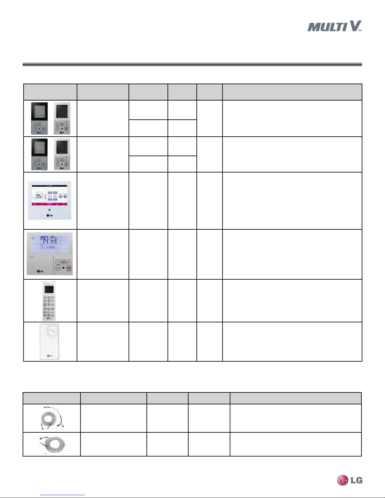
Table 4: Zone Controllers.
Zone Controller Name Model No. Case Color
Max Wire
Length (ft)
Description
Simple Controller with
mode selection
Simple Controller
without mode selection
LG Premium
Controller
LG Programmable
Thermostat
PQRCVCL0Q Black
PQRCVCL0QW White
PQRCHCA0Q Black
PQRCHCA0QW White
PREMTA000 Ivory 164
PREMTB10U White 164
Allows control of indoor unit on/off, operation mode, fan speed,
164
Allows control of indoor unit on/off, fan speed, and temperature
164
and temperature setpoint for up to 16 indoor units.
setpoint for up to 16 indoor units.
Allows control of indoor unit on/off, operation mode, occupied/
unoccupied temperature setpoints, fan speed, and air flow
direction for up to 16 indoor units. Programmable schedule with 5
events per day with control of occupied/unoccupied, on/off,
mode, setpoints and fan speed. Advanced functions include
two setpoint autochangeover, minimum difference between
setpoints, setback, timed override, target energy consumption
display, check energy display and master/slave.
Allows control of indoor unit on/off, operation mode, occupied
and unoccupied temperature setpoints, fan speed, and airflow
direction for up to 16 indoor units. Programmable schedule with
5 events per day with control of occupied unoccupied, on/off,
mode, setpoints and fan speed. Advanced functions include two
setpoint autochangeover, minimum difference between setpoints,
setback and timed override.
Wireless Handheld PQWRHQ0FDB Ivory ----
Wall-Mounted Remote
Temperature Sensor
PQRSTA0 Ivory 50
MULTI V Wall-Mounted Indoor Unit Engineering Manual
Before specifying or placing an order, refer to the V-Net Network Solution Engineering Product Data Book and review the detailed technical data provided to fully understand the capabilities and limitations of these
devices.
For information on controller compatibility refer to the Controls and Options Tables on pages 12 and 13.
Table 5: Zone Controller Communication Cables.
Communication Cable Name Model No. Wire Length (ft.) Description
Wired Remote Group
Control Cable Assembly
Wired Remote/Group Control
Extension Cable
Before specifying or placing an order, refer to the V-Net Network Solution Engineering Product Data Book and review the detailed technical data provided to fully understand the capabilities and limitations of these
devices.
For information on controller compatibility refer to the Controls and Options Tables on pages 12 and 13.
Due to our policy of continuous product innovation, some specications may change without notication.
LG Electr onics U.S.A., Inc., Engl ewood Cliffs , NJ. All rights re served. “LG” is a r egistered tra demark of LG Corp.
8 | INTRODUCTION
©
PZCWRCG3 33
PZCWRC1 33
Allows control of indoor unit on/off, operation mode, fan speed,
and temperature setpoint.
Allows remote temperature measurement for cassette and
ducted units.
Required when grouping multiple indoor units with a single
zone controller.
Increases the distance between a remote controller and an
indoor unit or between indoor units in a control group.
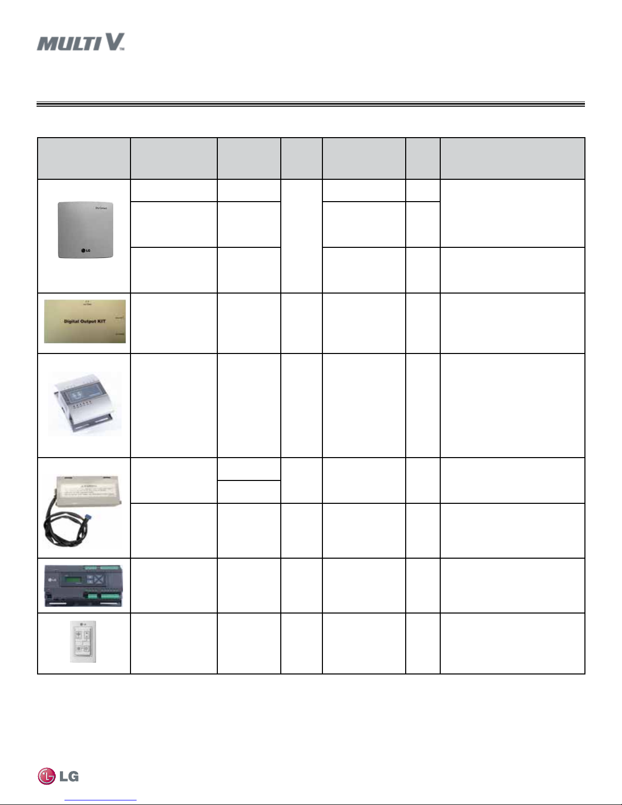
Table 6: Specialty Application Devices.
Specialty Application
Device
Name Model No.
Simple Dry Contact PQDSB1
Dry Contact for
Economizer, occupied/
unoccupied
Dry Contact Unit for
24V Thermostat
Digital Output
(DO) Kit
I/O Module
Auxiliary Heater
Relay Kit
PQDSBC1
PDRYCB300
PQNFP00T0
PEXPMB000.
ENCXLUS
PRARH0
PRARS0
CONTROLLERS OVERVIEW
Specialty Application Devices
Binary
Connect
to
Indoor
Unit
Comm
Bus
AC
Smart IV
and
ACP IV
Indoor
Unit
Application
On/Off, Run Status,
Error Status
On/Off, Mode,
Controller Lock, Power
Save, Run Status,
Error Status
On/Off, Thermo On/
Off, Mode, Fan Speed,
Run Status, Error
Status
On/Off 0/1
Third party equipment
control. Allows system
expansion through
Digital and Analog
inputs and outputs.
Third party
supplemental heat
control
Signals
Input/
Output
1/2
2/2
---
---
0/1
Description
Enables the indoor unit to be
controlled and monitored by third
party controls using binary inputs
and outputs.
Enables the indoor unit to be
controlled and monitored by a third
party thermostat or controller.
One 25A DPST normally open relay.
Used with central controller to control
third party device manually or by
schedule.
3 Digital Inputs: Dry Contact input only
3 Digital Outputs: Max. 2A@30VAC/DC
4 Analog Outputs: 0 to 10 VDC,
configurable; 0 to 20 mA, configurable
4 Universal Inputs individually
configurable as analog or digital:
Analog: Voltage. Current. Thermistor
(NTC, PT, Ni)
Digital for Dry Contact input only
Adds coordinated control of an
external heater with normal heat
pump operations.
Introduction
Auxiliary Two-Stage
Heater Relay Kit
Power Distribution
Indicator (PDI)
Premium
Mode Selector Switch PRDSBM
Before specifying or placing an order, refer to the V-Net Network Solution Engineering Product Data Book and review the detailed technical data provided to fully understand the capabilities and limitations of these
devices.
For information on controller compatibility refer to the Controls and Options Tables on pages 12 and 13.
Due to our policy of continuous product innovation, some specications may change without notication.
LG Electr onics U.S.A., Inc., Engl ewood Cliffs , NJ. All rights re served. “LG” is a r egistered tra demark of LG Corp.
©
PRARH1
PQNUD1S41
Indoor
Unit
Comm
Bus
Outdoor
Unit
Third party
supplemental heat
control
Energy
consumption
monitoring
Multi V Heat
Pump Only
0/2
8 Watt
Node
Meters
---
Adds coordinated control of an
external heater with normal heat
pump operations.
Monitors total outdoor unit power
consumption for up to eight systems,
and distributes per indoor unit based
on weighted calculation.
Locks outdoor unit into Heat,
Cool, or Fan Mode.
INTRODUCTION | 9
CONTROLLERS OVERVIEW
Central Controllers
Table 7: Central Controllers (connect to the outdoor unit terminals Internet A, Internet B).
Central
Controller
Name Model No.
AC Smart IV
PACS4B000.
ENCXLUS
Devices
per
Controller
128 16 128 1
Systems
per Comm
Bus
Devices
per Comm
Bus
No. of
Comm
Bus
Ports
Binary
Signals
Input/
Output
2 DI /
2 DO
Power,
Conn
24 VAC
Description
Monitors / operates indoor units
through a touch screen. Manages
up to 128 devices. Advanced
functions include programmable
schedules, temperature setpoint
range lock, remote controller lock,
run time limit, manual control and
scheduling of digital output kit,
peak/demand control, visual floor
plan navigation, web access,
operation and error history log, one
digital input and two digital outputs
for device interlocking and error
e-mail notification.
AC Ez PQCSZ250S0 32 16 256 1 ---
Advanced
Control
Platform IV
(ACP IV)
Before specifying or placing an order, refer to the V-Net Network Solution Engineering Product Data Book and review the detailed technical data provided to fully understand the capabilities and limitations of these
devices.
For information on controller compatibility refer to the Controls and Options Tables on pages 12 and 13.
PACP4B000.
ENCXLUS
256 16 64 4 10/4 24 VAC
12 VDC,
ODU
Provides for scheduling in addition
to basic indoor unit control and
monitoring.
Provides for scheduling, remote
controller lock, setpoint range limit,
web access, peak/demand control,
PDI integration, and AC Manager
Plus integration advanced
functionality in addition to basic unit
control and monitoring.
MULTI V Wall-Mounted Indoor Unit Engineering Manual
Due to our policy of continuous product innovation, some specications may change without notication.
LG Electr onics U.S.A., Inc., Engl ewood Cliffs , NJ. All rights re served. “LG” is a r egistered tra demark of LG Corp.
10 | INTRODUCTION
©
CONTROLLERS OVERVIEW
Integration Solutions
Table 8: Summary Data—Integration Solutions (connect to outdoor unit terminals Internet A, Internet B).
Systems
per
Comm
Bus
Devices
per Comm
Bus
Integration
Solution
Name Model No.
Devices
per
Controller
ACP IV
®
BACnet
PQNFB17C1 256 16 256 4 24 VAC 10/4
Gateway*
LonWorks
Gateway*
Before specifying or placing an order, refer to the V-Net Network Solution Engineering Product Data Book and review the detailed technical data provided to fully understand the capabilities and limitations of these
devices.
For information on controller compatibility refer to the Controls and Options Tables on pages 12 and 13.
TM
* BACnet
is a trademark of ASHRAE; LonWorksTM is a trademark of Echlelon Corporation.
®
PLNWKB100 64 16 64 1 24 VAC 2/2
No. of
Comm
Bus
Ports
Power
Binary
Signals
Input/
Output
Description
Allow integration of LG equipment
for control and monitoring by open
®
protocol BACnet
and LonWorks®
building automation and controls
systems.*
Introduction
Due to our policy of continuous product innovation, some specications may change without notication.
LG Electr onics U.S.A., Inc., Engl ewood Cliffs , NJ. All rights re served. “LG” is a r egistered tra demark of LG Corp.
©
INTRODUCTION | 11
CONTROLLERS OVERVIEW
Options and Features
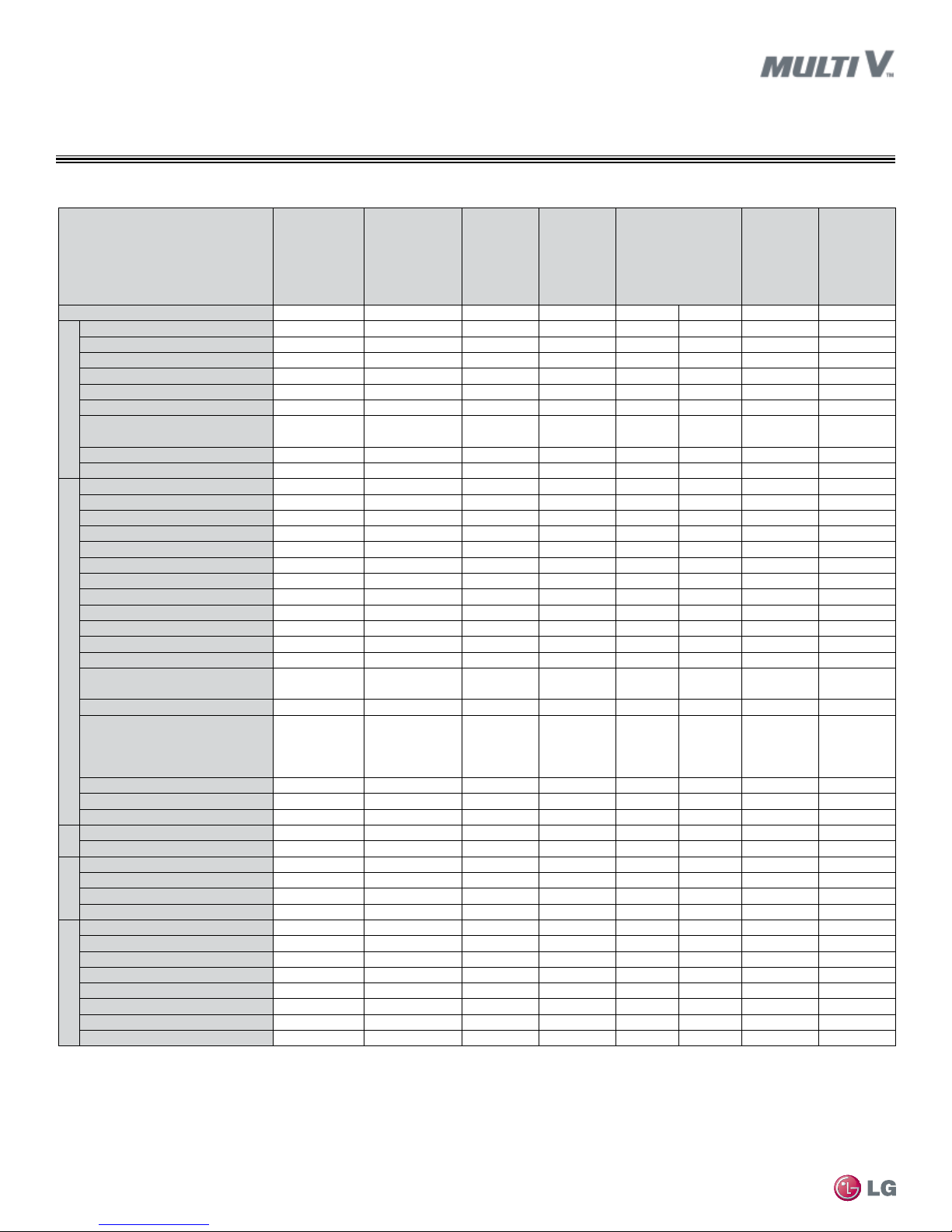
Table 9: Options and Features.
Feature
Nominal Chassis Size (MBh)
Air supply outlets
Airflow direction (left/right)
Auto airflow direction (up/down)
Fan speed (Heating mode)
Fan speed (Cooling mode)
Fan speed (fan mode)
Airow
Chaos swing (random louver
swing)
Chaos wind (random fan speed)
Jet-cool (power cooling)
E.S.P. control
High ceiling
Auto-restart after power restore
Hot start
Diagnostics
Auto changeover
Auto operation
1
6
Auto clean (coil dry)
Child lock
Dual thermistor control
Dual set-point control
Filter life display
Operation
Power consumption display
(with PDI)
Forced operation
Wall
Mounted—
Standard
Finish
5–24 7–24 7–24 18–24 5–18 24–48 7–96 7–24
1 1 1 2 4 4 1 1
manual auto
√ √ √ √ √ √
3 3 4 4 4 4 3 3
4 4 5 5 5 5 3 3
3 3 4 4 4 4 3 3
√ √
√ √ √ √ √ √
√ √ √ √ √ √
√ √ √ √ √ √ √ √
√ √ √ √ √ √ √ √
√ √ √ √ √ √ √ √
√ √ √ √ √ √ √ √
√ √ √ √ √ √ √ √
√ √
√ √ √ √ √ √ √ √
√ √ √ √ √ √ √ √
√ √ √ √ √ √ √ √
√ √ √ √ √ √ √ √
√ √ √ √ √ √ √ √
√ √ √ √ √ √
Wall Mounted—
ART COOL™
Mirror
1-Way
Cassette
√ √ √ √ √ √
√ √ √ √
Group control – Requires the
use of one Group control cable
kit (PZCWRCG3) for every
√ √ √ √ √ √ √ √
additional indoor unit
Timer (on/off)
Weekly schedule
Test operation mode
3
Plasma
Filter
Washable anti-fungal
2
7-day programmable controller
MULTI V Wall-Mounted Indoor Unit Engineering Manual
Simple controller w/mode
Simple controller w/o mode
Controllers
Wireless controller
Condensate lift
Ventilation air
Casing
Standard grille
Auto elevation grille
Others
Suction grille
√ √ √ √ √ √ √ √
√ √ √ √ √ √ √ √
√ √ √ √ √ √ √ √
√ √ √ √ √ √
√ √ √ √ √ √ √ √
o o o o o o o o
o o o o o o o o
o o o o o o o o
o o o o o o o
√ √ √ √ √ √
√ √
√ √ √ √ √ √
√ √ √ √
Suction canvas
Aux. heat kit
1
For Heat Recovery systems only.
2
Primary washable filters.
3
Secondary plasma filters.
4
Requires 7-day programmable zone controller.
5
Requires ventilation kit PTVK430 or PTVK410+PTVK420 (For TP, TN, TM frames)(Temperature, humidity, and volume limitations apply).
6
Heat Pump systems only.
2-Way
Cassette
4-Way Cassette
5
√
o
√ = Standard feature
o = Unit option
5
Ducted High
Static
4
√ √
Ducted Low
Static
4
o
Due to our policy of continuous product innovation, some specications may change without notication.
LG Electr onics U.S.A., Inc., Engl ewood Cliffs , NJ. All rights re served. “LG” is a r egistered tra demark of LG Corp.
12 | INTRODUCTION
©
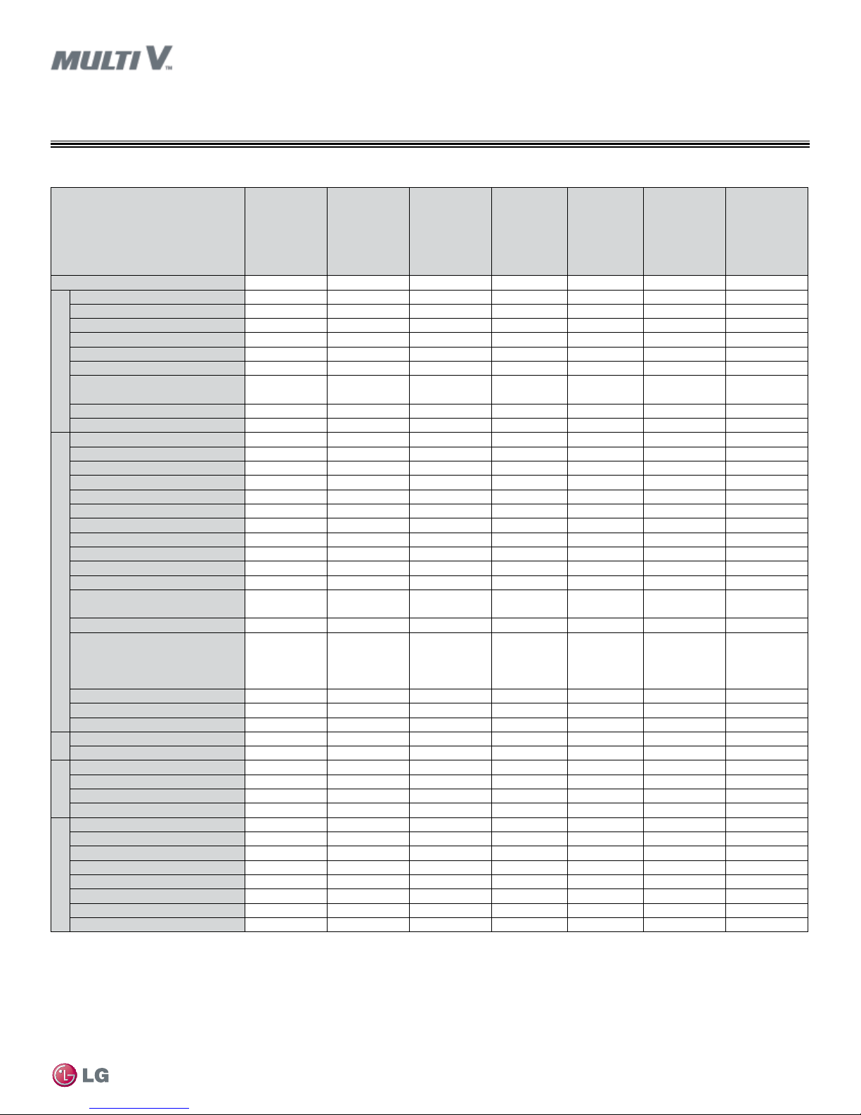
Table 10: Options and Features, continued.
CONTROLLERS OVERVIEW
Options and Features
Feature
Nominal Chassis Size (MBh)
Air supply outlets
Airflow direction (left/right)
Ducted Low
Static—
Bottom Return
7–24 12-36 42-53 18–24 9–12 7–24 7–24
1 1 1 1 1 1 1
Vert.-Horiz.
AHU (NJ)
Vert.-Horiz.
AHU (NK)
Ceiling
Suspended
manual manual
Auto airflow direction (up/down)
Fan speed (Heating mode)
Fan speed (Cooling mode)
Fan speed (fan mode)
Airow
Chaos swing (random louver
3 3 3 3 3 3 3
3 3 3 4 4 3 3
3 3 3 3 3 3 3
swing)
Chaos wind (random fan speed)
Jet-cool (power cooling)
E.S.P. control
Auto-restart after power restore
Hot start
Diagnostics
Auto changeover
Auto operation
1
6
√ √ √
√ √ √ √ √ √ √
√ √ √ √ √ √ √
√ √ √ √ √ √ √
√ √ √ √ √ √ √
√ √ √ √ √ √ √
Auto clean (coil dry)
Child lock
Dual thermistor control
Dual set-point control
Filter life display
Power consumption display
Operation
(with PDI)
√ √ √ √ √ √ √
√ √ √ √ √ √ √
√ √ √ √ √ √ √
√ √ √ √ √ √ √
√ √ √ √ √ √ √
Forced operation
Group control – Requires the
use of one Group control cable
kit (PZCWRCG3) for every
√ √ √ √ √ √ √
additional indoor unit
Timer (on/off)
Weekly schedule
Test operation mode
3
Plasma
Filter
Washable anti-fungal
2
7-day programmable controller
Simple controller w/mode
Simple controller w/o mode
Controllers
Wireless controller
Condensate lift
Ventilation air
√ √ √ √ √ √ √
√ √ √ √ √ √ √
√ √ √ √ √ √ √
√ √
√ √ √ √ √
o o o o o
o o o o o o o
o o o o o o o
4
o
o o o o o
√
√
Casing
Standard grille
Auto elevation grille
Others
Suction grille
Suction canvas
Aux. heat kit
1
For Heat Recovery systems only.
2
Primary washable filters.
3
Secondary plasma filters.
4
Requires 7-day programmable zone controller.
5
Requires ventilation kit PTVK430 or PTVK410+PTVK420 (For TP, TN, TM frames)(Temperature, humidity, and volume limitations apply).
6
Heat Pump systems only.
o
o
√ √
Convertible
Surface
Mount
Floor Mount—
Cased
√ √
√ √
√ √
√ √
√ √ √
√ = Standard feature
o = Unit option
Floor Mount—
Uncased
Introduction
4
4
o
Due to our policy of continuous product innovation, some specications may change without notication.
LG Electr onics U.S.A., Inc., Engl ewood Cliffs , NJ. All rights re served. “LG” is a r egistered tra demark of LG Corp.
©
INTRODUCTION | 13
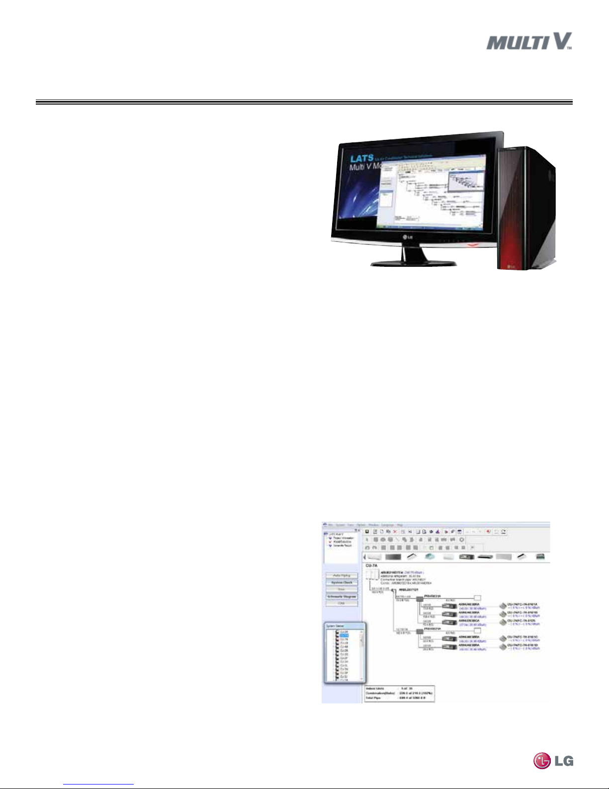
LATS MULTI V PIPING
DESIGN SOFTWARE
The proper design and installation of the refrigerant piping system
is a critical element of a Multi V system. Multi V Heat Pump systems
require two pipes between components – a liquid line and a vapor
line. Multi V Heat Recovery systems require three pipes between the
outdoor unit and the heat recovery unit – a liquid line, a low-pressure vapor line, and a high-pressure vapor line. A properly designed
refrigerant piping system ensures that refrigerant is delivered to the
indoor unit coils for optimal system performance and capacity.
LG Air Conditioner Technical Solution (LATS) software is a total
design solution for LG Multi V air conditioning systems. This
Windows®-based application assists the design engineer with
specifying and sizing outdoor and indoor units (by calculating
component capacity based on design conditions), laying out the
refrigeration distribution pipe system, checking piping limitations,
calculating refrigerant charge, and generating equipment schedules
and piping diagrams in (.dxf) format for use on CAD building design
drawings.*
* Windows® is a registered mark of Microsoft® Corporation.
To ensure that the refrigerant piping design meets LG’s quality standards, a LATS refrigerant piping design must be provided with
every Multi V order. Following the installation, if any changes or variations to the design are necessary, a new LATS file must be
created and provided to LG prior to system commissioning to ensure the proper pipe size has not changed.
Design Choices
LATS Multi V software is flexible, offering the HVAC system engineer an easy to use Tree mode.
Tree Mode
Using the Tree mode, the engineer can quickly create a one-line schematic drawing of a Multi V system. Integration of the engineered pipe
system into the building drawings is done at a later date by the draftsperson using standard drafting software tools.
• Import building loads from an external file (.xls format).
• System components selected using an easy drag and drop process.
• Automatically analyzes and checks the design complies with most
piping design limitations.
• Sizes refrigerant piping.
• Generates a system engineering report (.xls format).
MULTI V Wall-Mounted Indoor Unit Engineering Manual
• Generates an equipment schedule (.xls or .dxf format).
• Generates a system piping diagram (.dxf format).
Figure 1: Screenshot of LATS Pipe System Design Tool in Tree Mode.
LATS Report
LATS Multi V software generates a report file (.xls format) containing
project design parameters, cooling and heating design day system
component performance, and capacity data. The report calculates
the system combination ratio, calculates the system refrigerant
charge, and provides detailed bill of material information including a
list of Multi V outdoor units, air handlers, control devices, accessories, refrigerant pipe sizes segregated by building, by system, by pipe
size, and by pipe segments.
Due to our policy of continuous product innovation, some specications may change without notication.
LG Electr onics U.S.A., Inc., Engl ewood Cliffs , NJ. All rights re served. “LG” is a r egistered tra demark of LG Corp.
14 | INTRODUCTION
©
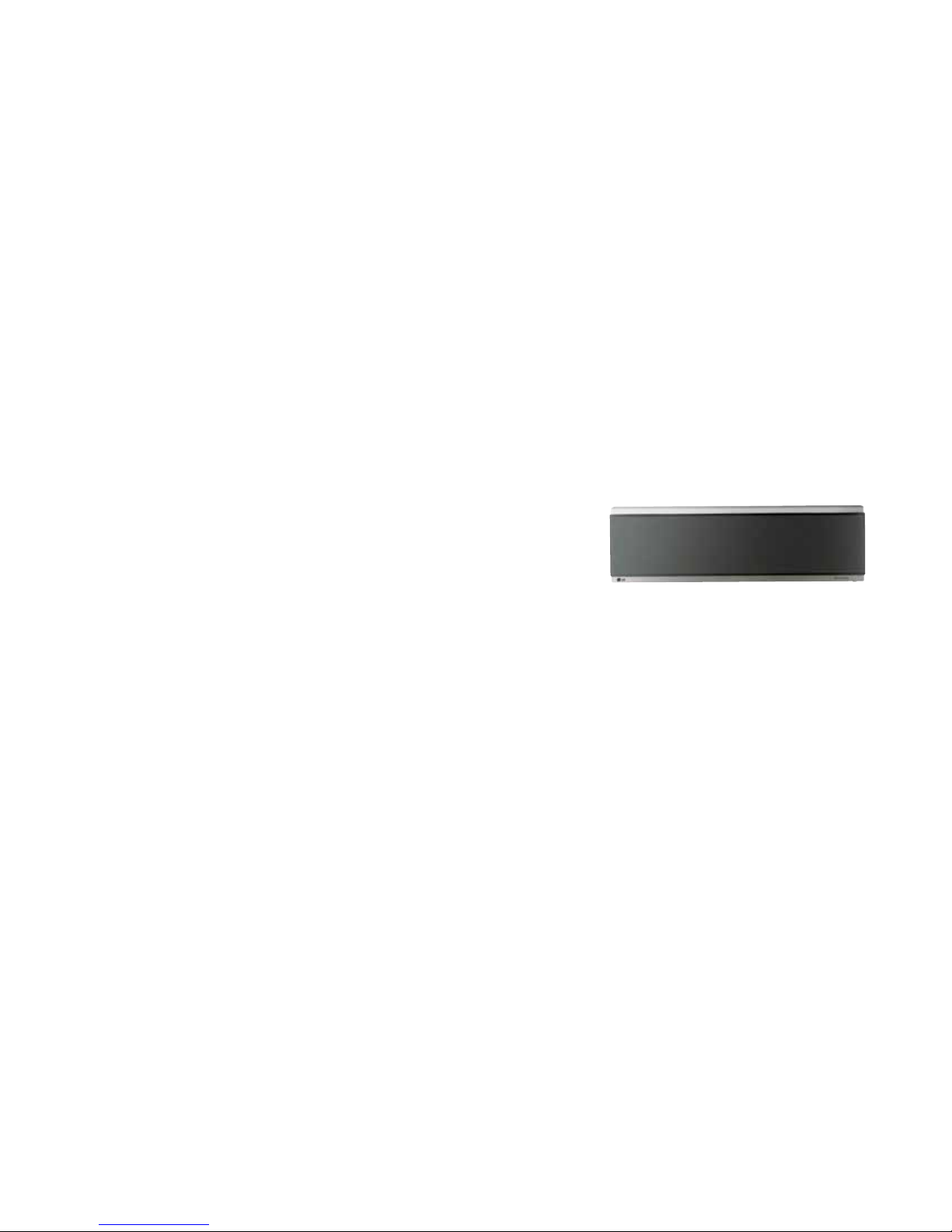
TM
ART COOL
MIRROR
WALL-MOUNTED
Mechanical Specifications on page 16
General Data on page 17
Electrical Data on page 18
External Dimensions on page 19
Electrical Wiring Diagram on page 21
Refrigerant Flow Diagrams on page 23
Acoustic Data on page 24
Air Velocity / Temperature Distribution on page 26
Capacity Tables on page 29
ART COOLTM MIRROR
Mechanical Specications
Casing
Units are designed to mount on a vertical surface and come complete with an installation mounting guide and a separate hanging
bracket. The unit case is manufactured with coated metal. Cold
surfaces are covered with a coated polystyrene insulating material.
Finish
The unit case has a light gray/silver matte finish. The front surface of
the unit has an architectural flat panel smoked mirror finish.
Fan Assembly and Control
The unit has a single, direct-drive, crossflow tangential Sirocco fan
made of high strength ABS BSN-7530 polymeric resin. The fan motor
is a Brushless Digitally Controlled (BLDC) design with permanently
lubricated and sealed ball bearings. The fan motor includes thermal,
overcurrent and low RPM protection. The fan / motor assembly is
mounted on vibration attenuating rubber grommets. The fan impeller
is statically and dynamically balanced. The fan speed is controlled
using a microprocessor-based direct digital control algorithm that
provides a high fan speed in cooling thermal ON and low fan speed
in cooling thermal OFF, high fan speed in heating thermal ON and
fan off in heating thermal OFF. The fan speeds can be field adjusted
between low, medium, and high speeds. The fan speed algorithm
provides a field-selectable fixed-speed or auto-speed setting that
changes the fan speed to simulate natural airflow.
Air Filter
Return air is filtered with a removable, washable filter with antifungal treatment. The unit is also equipped with a plasma filter. Filter
access is from the front of the unit without the use of tools.
Airflow Guide Vanes
The indoor unit is provided with a motorized sweeping guide vane
that automatically changes the direction of airflow from side-to-side
and up-and-down.
Microprocessor Control
The unit is provided with an integrated microprocessor controller
capable of performing functions necessary to operate the system
without the use of a wall-mounted controller. A temperature thermistor is factory mounted in the return air stream. All unit operation parameters, excluding the operating schedule, are stored in
non-volatile memory resident on the unit microprocessor. Operating
MULTI V Wall-Mounted Indoor Unit Engineering Manual
schedules are stored in select models of the optional, wall-mounted,
local or central controllers. The field-supplied communication cable
between the indoor unit(s) and outdoor unit is to be a minimum of 18
AWG, two conductor, stranded, and shielded cable (RS-485), terminated via screw terminals on the control boards. The microprocessor
control provides the following functions: self-diagnostics, auto restart
following power restoration, test run, and will operate the indoor unit
using one of five operation modes:
1. Auto Changeover (Heat Recovery only)
2. Heating
3. Cooling
4. Dry
5. Fan Only
For Heat Recovery systems the Auto Changeover setting automatically switches control of the indoor unit between Cooling and Heating
modes based on
space temperature
conditions.
For Heat Pump
systems, heated or
cooled air delivery is
dependent upon outdoor unit operating mode. In Heating mode, the
microprocessor control will activate indoor unit operation when the
indoor room temperature falls below setpoint temperature. At which
point, a signal is sent to the outdoor unit to begin the heating cycle.
The indoor unit fan operation is delayed until coil pipe temperature
reaches 76°F. Significant airflow is generated when pipe temperature
reaches 80°F. A field-selectable option maintains fan operation for
30 minutes following cooling cycle operations. The unit is equipped
with an infrared receiver designed to communicate with an LG
wireless remote controller. In lieu of wireless remote or factory return
air thermistor, screw terminals on the microprocessor circuit board
accommodate various models of wall-mounted local controllers.
The unit microprocessor is capable of accepting space temperature
readings concurrently or individually from either:
1. Wall-mounted wired controller(s)
2. Factory-mounted return air thermistor
A single indoor unit has the capability of being controlled by up to
two local wired controllers. The microprocessor controls space temperature using the value provided by the temperature sensor sensing
a space temperature that is farthest away from the temperature setpoint. The microprocessor control provides a cooling mode test cycle
that operates the unit for 18 minutes without regard to the space
temperature. If the system is provided with an optional wall-mounted
local or central controller, displayed diagnostic codes are specific,
alpha-numeric, and provide the service technician with a reason for
the code displayed.
Handling Condensate
The unit is designed for gravity draining of condensate. LG provides
a factory insulated flexible drain hose. If condensate lift / pumps are
needed for the application, they are to be field provided.
Condensate Drain Pan
The condensate drain pan is constructed of EPS (expandable polystyrene resin).
Coil
The indoor unit coil is constructed with grooved design copper tubes
with slit coil fins, two (two) rows, eighteen (18) fins per inch.
Controls Features
• Auto changeover
(Heat Recovery only)
• Auto operation
• Auto clean (coil dry)
• Child lock
• Dual thermistor control
• Group control
1
Requires wireless controller.
1
• Hot start
• Self diagnostics
• Timer (on/off)
• Weekly schedule
• Auto direction/swing (up/down)
• Auto direction (left/right)
• Fan speed control
• Jet cool (fast cooling)
16 | ART COOL
TM
Due to our policy of continuous product innovation, some specications may change without notication.
LG Electr onics U.S.A., Inc., Engl ewood Cliffs , NJ. All rights re served. “LG” is a r egistered tra demark of LG Corp.
©
Table 11: Art Cool Mirror Wall-Mounted (SE, S8 Frames) Indoor Unit General Data.
Model No. ARNU073SER2 ARNU093SER2 ARNU123SER2 ARNU153SER2 ARNU183S8R2 ARNU243S8R2
Cooling Mode Performance
Capacity (Btu/h)
Power Input1 (W)
7,500 9,600 12,300 15,400 19,100 24,200
40 40 40 40 35 35
Heating Mode Performance
Capacity (Btu/h)
Power Input1 (W)
8,500 10,900 13,600 17,100 21,500 27,300
40 40 40 40 35 35
Entering Mixed Air
Cooling Max (°F WB)
Heating Min (°F DB)
76 76 76 76 76 76
59 59 59 59 59 59
Unit Data
2
Refrigerant Type
Refrigerant Control
Sound Pressure3 dB(A) (H/M/L)
Net Unit Weight (lbs.)
Shipping Weight (lbs.)
Communication Cable4
(No. x AWG)
R410A R410A R410A R410A R410A R410A
EEV EEV EEV EEV EEV EEV
37 / 33 / 23 39 / 35 / 25 41 / 36 / 27 42 / 36 / 27 37 / 34 / 31 43 / 37 / 32
25 25 25 25 34 34
29 29 29 29 38 38
2 x 18 2 x 18 2 x 18 2 x 18 2 x 18 2 x 18
Fan
Type
Quantity
Motor/Drive
Airflow Rate H/M/L (CFM)
Cross Flow Cross Flow Cross Flow Cross Flow Cross Flow Cross Flow
1 1 1 1 1 1
Brushless Digitally Controlled / Direct
247 / 212 / 141 282 / 247 / 177 353 / 283 / 212 371 / 283 / 212 508 / 459 / 388 632 / 508 / 424
Piping
Liquid Line (in., O.D.)
Vapor Line (in., O.D.)
Condensate Line (in., I.D.)
EEV: Electronic Expansion Valve
Power wiring is field supplied and must comply with the applicable local and national codes.
This unit comes with a dry nitrogen charge.
This data is rated 0 ft above sea level, with 25 ft of refrigerant line per indoor unit and a 0 ft level
difference between outdoor and indoor units. All capacities are net with a combination ratio between
95-105%.
Cooling capacity rating obtained with air entering the indoor coil at 80ºF dry bulb (DB) and 67ºF wet
bulb (WB) and outdoor ambient conditions of 95ºF dry bulb (DB).
Heating capacity rating obtained with air entering the indoor unit at 70ºF dry bulb (DB) and outdoor
ambient conditions of 47ºF dry bulb (DB) and 43ºF wet bulb (WB).
1/4 Flare 1/4 Flare 1/4 Flare 1/4 Flare 1/4 Flare 3/8 Flare
1/2 Flare 1/2 Flare 1/2 Flare 1/2 Flare 1/2 Flare 5/8 Flare
5/8 5/8 5/8 5/8 5/8 5/8
1
Power Input is rated at high speed.
2
Take appropriate actions at the end of HVAC equipment life to recover, recycle, reclaim or destroy
R410A refrigerant according to applicable regulations (40 CFR Part 82, Subpart F) under section 608
of CAA.
3
Sound Pressure levels are tested in an anechoic chamber under ISO Standard 3745.
4
All communication cable to be minimum 18 AWG, 2-conductor, stranded, shielded and must comply
with applicable and national code. Ensure the communications cable is properly grounded at the master
outdoor unit only. Do not ground the ODU-IDU communications cable at any other point.
ART COOLTM MIRROR
General Data
Art Cool
TM
Mirror
Due to our policy of continuous product innovation, some specications may change without notication.
LG Electr onics U.S.A., Inc., Engl ewood Cliffs , NJ. All rights re served. “LG” is a r egistered tra demark of LG Corp.
©
ART COOLTM | 17
ART COOLTM MIRROR
Electrical Data
Table 12: Art Cool Mirror Wall-Mounted Indoor Unit Electrical Data.
Model Number
Voltage
Range
MCA MOP Rated Amps (A)
Power Supply Power Input (W)
Hz Volts Phase Cooling Heating
SE Frames
ARNU073SER2
ARNU093SER2 0.29 0.3 40 40
ARNU123SER2 0.29 0.3 40 40
187-253
0.29
15
0.3
40 40
60 208-230V 1
ARNU153SER2 0.29 0.3 40 40
S8 Frames
ARNU183S8R2
ARNU243S8R2 0.29 0.3 35 35
MCA : Minimum Circuit Ampacity.
MOP : Maximum Overcurrent Protection.
187-253
0.29
Units are suitable for use on an electrical system where voltage supplied to unit terminals is within the listed range limits.
Select wire size based on the larger MCA value.
Instead of a fuse, use the circuit breaker.
15
0.3
60 208-230V 1
35 35
MULTI V Wall-Mounted Indoor Unit Engineering Manual
18 | ART COOL
TM
Due to our policy of continuous product innovation, some specications may change without notication.
LG Electr onics U.S.A., Inc., Engl ewood Cliffs , NJ. All rights re served. “LG” is a r egistered tra demark of LG Corp.
©
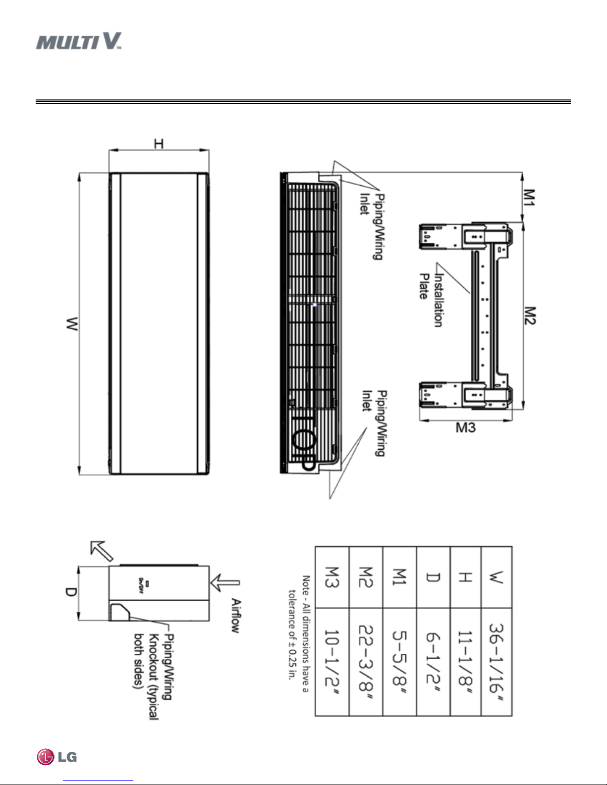
Figure 2: ARNU073SER2, ARNU093SER2, ARNU123SER2, ARNU153SER2 Dimensions.
ART COOLTM MIRROR
External Dimensions
SE Frame
Art Cool
TM
Mirror
Due to our policy of continuous product innovation, some specications may change without notication.
LG Electr onics U.S.A., Inc., Engl ewood Cliffs , NJ. All rights re served. “LG” is a r egistered tra demark of LG Corp.
©
ART COOLTM | 19
 Loading...