


AF-044P

PLASMA TV
SERVICE MANUAL
CAUTION
BEFORE SERVICING THE CHASSIS,
READ THE SAFETY PRECAUTIONS IN THIS MANUAL.
CHASSIS : AF-044P
MODEL : DU-42PY10X DU-42PY10XH
CANADA : http//biz.lgservice.com
USA : http//www.lgservice.com
: http//lgservice.com/techsup.html
TV/VIDEO
MENU
VOL CH
POWER
TV GUIDE
- 2 -
SAFETY PRECAUTIONS
Many electrical and mechanical parts in this chassis have special safety-related characteristics. These parts are identified by in
the Schematic Diagram and Replacement Parts List.
It is essential that these special safety parts should be replaced with the same components as recommended in this manual to
prevent X-RADIATION, Shock, Fire, or other Hazards.
Do not modify the original design without permission of manufacturer.
General Guidance
An lsolation Transformer should always be used during
the servicing of a receiver whose chassis is not isolated from
the AC power line. Use a transformer of adequate power rating
as this protects the technician from accidents resulting in
personal injury from electrical shocks.
It will also protect the receiver and it's components from being
damaged by accidental shorts of the circuitary that may be
inadvertently introduced during the service operation.
If any fuse (or Fusible Resistor) in this monitor is blown, replace
it with the same specified type.
When replacing a high wattage resistor (Oxide Metal Film
Resistor, over 1W), keep the resistor 10mm away from PCB.
Keep wires away from high voltage or high temperature parts.
Leakage Current Cold Check(Antenna Cold Check)
With the instrument AC plug removed from AC source,
connect an electrical jumper across the two AC plug prongs.
Place the AC switch in the on positioin, connect one lead of
ohm-meter to the AC plug prongs tied together and touch other
ohm-meter lead in turn to each exposed metallic parts such as
antenna terminals, phone jacks, etc.
If the exposed metallic part has a return path to the chassis, the
measured resistance should be between 1MΩ and 5.2MΩ.
When the exposed metal has no return path to the chassis the
reading must be infinite.
An other abnormality exists that must be corrected before the
receiver is returned to the customer.
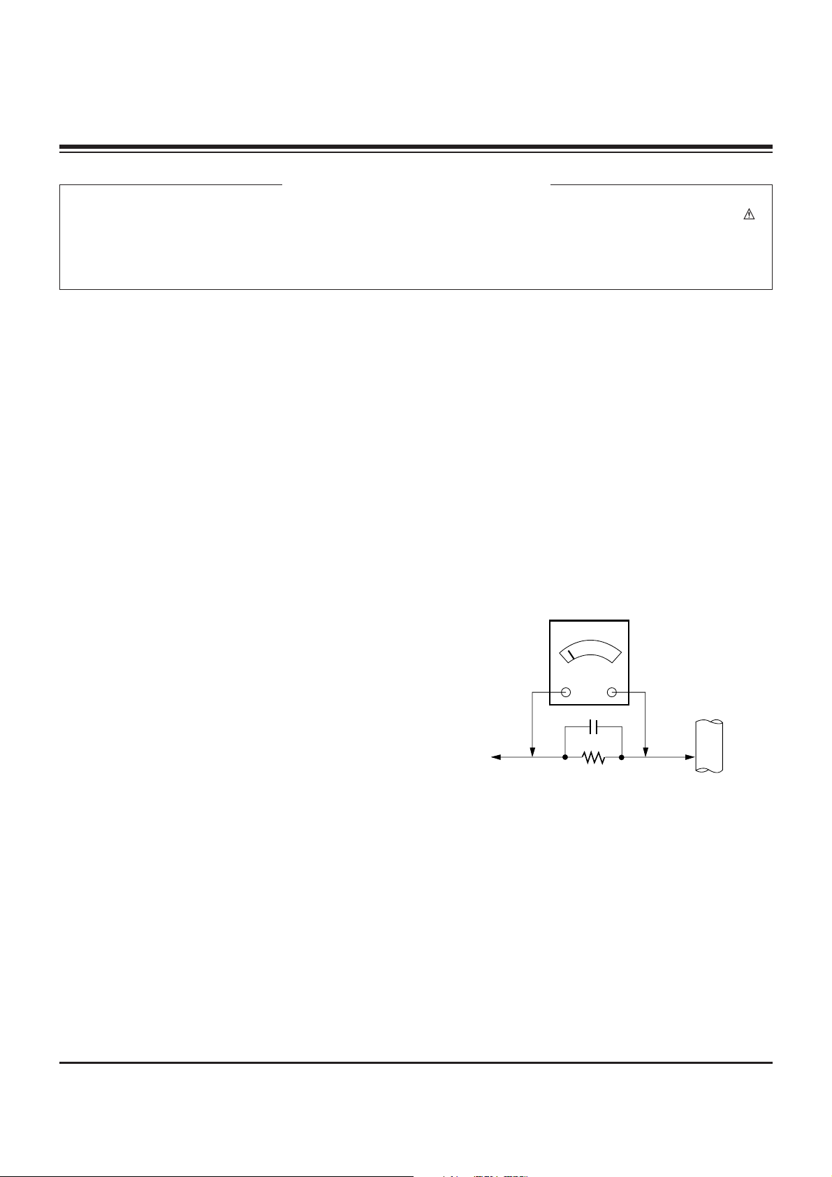
Leakage Current Hot Check (See below Figure)
Plug the AC cord directly into the AC outlet.
Do not use a line Isolation Transformer during this check.
Connect 1.5K/10watt resistor in parallel with a 0.15uF capacitor
between a known good earth ground (Water Pipe, Conduit, etc.)
and the exposed metallic parts.
Measure the AC voltage across the resistor using AC
voltmeter with 1000 ohms/volt or more sensitivity.
Reverse plug the AC cord into the AC outlet and repeat AC
voltage measurements for each esposed metallic part. Any
voltage measured must not exceed 0.75 volt RMS which is
corresponds to 0.5mA.
In case any measurement is out of the limits sepcified, there is
possibility of shock hazard and the set must be checked and
repaired before it is returned to the customer.
Leakage Current Hot Check circuit
CANADA: LG Electronics Canada, Inc. 550 Matheson
Boulevard East Mississauga, Ontario L4Z 4G3
USA : LG Customer Interactive Center
P.O.Box 240007, 201 James Record Road Huntsville,
AL 35824
Digital TV Hotline 1-800-243-0000
1.5 Kohm/10W
To Instrument's
exposed
METALLIC PARTS
Good Earth Ground
such as WATER PIPE,
CONDUIT etc.
AC Volt-meter
IMPORTANT SAFETY NOTICE
0.15uF

- 3 -
DESCRIPTION OF CONTROLS...........................................4
ADJUSTMENT INSTRUCTIONS ..........................................7
PRINTED CIRCUIT BOARDS.............................................17
BLOCK DIAGRAM...............................................................23
EXPLODED VIEW...............................................................24
EXPLODED VIEW PARTS LIST.........................................25
REPLACEMENT PARTS LIST............................................26
SCHEMATIC DIAGRAM..........................................................
TABLE OF CONTENTS
- 4 -
TV/VIDEO
MENU
VOL CH
POWER
TV GUIDE
POWER
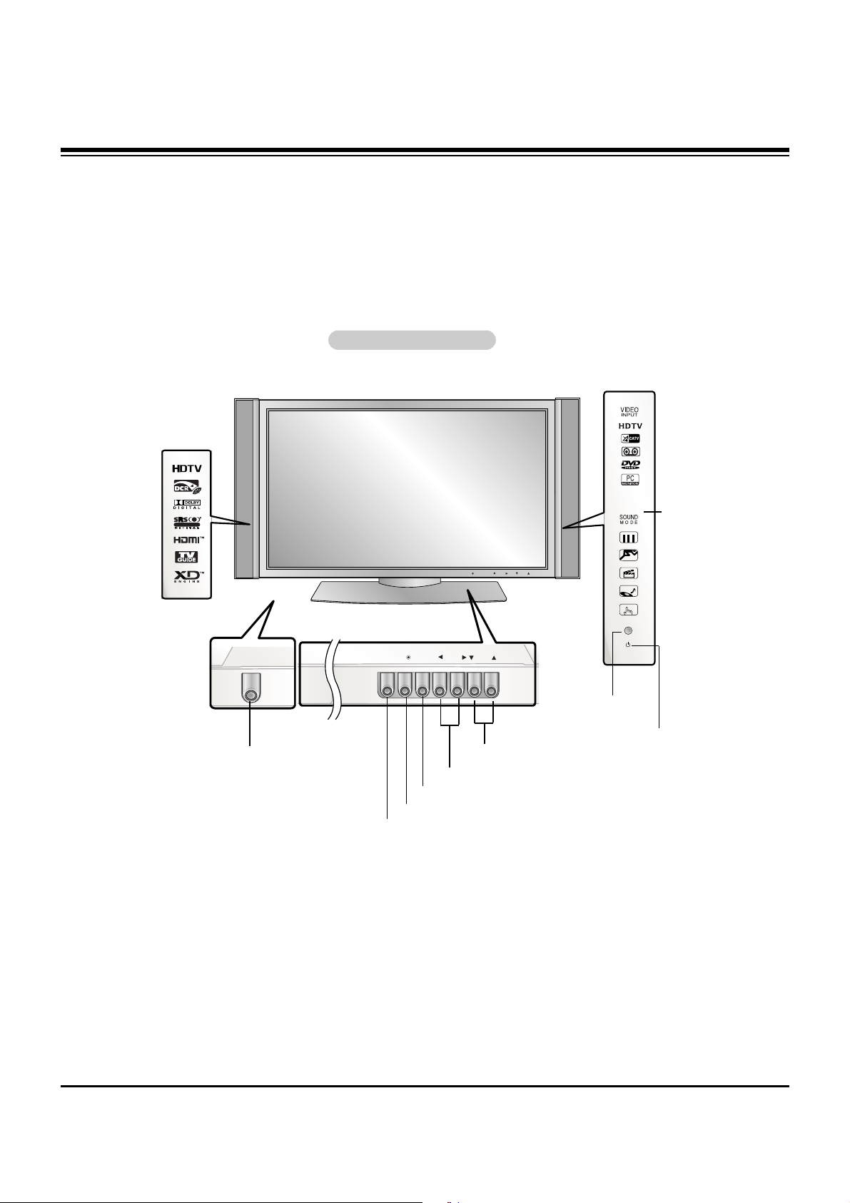
Controls
Controls
- This is a simplified representation of front panel.
Here shown may be somewhat different from your TV.
Front Panel Controls
Front Panel Controls
TV/VIDEO
MENU
VOL
CH
TV GUIDE
MENU Button
TV/VIDEO Button
POWER Button
VOLUME (FF,GG) Buttons
CHANNEL (EE, DD) Buttons
INDEX
Switches
LED Display
on or off.
TV GUIDE Button
Remote Control
Sensor
R
TTruSurround XTruSurround XT
Power Indicator
Illuminates orange in standby mode, Illuminates green
when the TV is turned on.
(If power isn’t turn on in red,
contact your service center.)
DESCRIPTION OF CONTROLS
- 5 -
Connection Options
Connection Options
R
S-VIDEO VIDEO
L / MONO
AUDIO
FRONT A/V INPUT
DVI
COMPONENT2
DIGITAL AUDIO(OPTICAL)
VIDEO INPUT
AUDIO INPUT
CABLE
HDMI /
DVI(VIDEO)
Cable
ANTENNA
AC INPUT
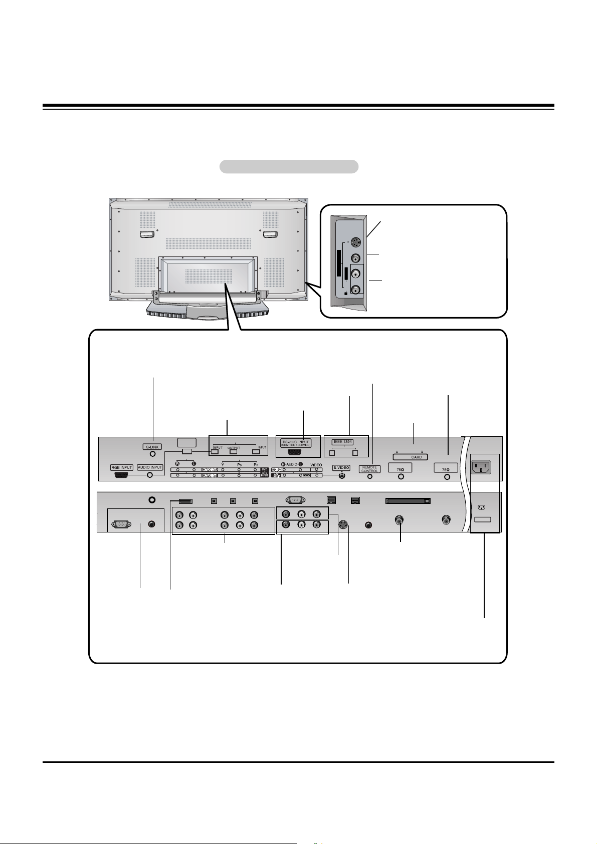
Back Connection Panel
Back Connection Panel
Antenna Inputs
Connect antenna signals to the TV, either
directly or through
your cable box.
RGB/AUDIO
INPUT
Connect the monitor output connector from a PC to
the appropriate
input port.
Digital Audio (DVI: Digital
Visual
Interface/Component2)
Input/
Digital Audio Output
Connect digital audio from
various types of equipment.
Note: In standby mode,
these ports will not work.
DVD/DTV Input
(Component 1-2)
Connect a component
video/audio device to
these jacks.
Monitor Output
Connect a second
TV or Monitor.
Remote Control Port
Connect your wired
remote control here.
S-Video Input
Connect S-Video out
from an S-VIDEO
device to the SVIDEO input.
IEEE1394
Connect
DVHS or
MicroMV to
IEEE1394
Connector.
CABLE Inputs
Connect cable
signals to the TV,
either directly or
through your
cable box.
RS-232C
INPUT (CONTROL/SERVICE) PORT
Connect to the
RS-232C port
on a PC.
CableCARD
Used for
CableCARD
received Cable
Service Provider.
G-LINK
Connect an
IR controller
to this jack.
HDMI/DVI(VIDEO)
Connect a
HDMI/DVI(Video)
signal to this jack.
S-VIDEO Input
A connection available to provide better picture quality than the video input.
VIDEO Input
Connects the video signal from a
video device.
AUDIO Input
Use to connect to hear stereo sound
from an external device.
Power Cord Socket
This TV operates on an AC power. The voltage is indi-
cated on the Specifications page. Never attempt to oper-
ate the TV on DC power.
Audio/Video Input
Connect audio/video
output from an external device to these
jacks.
DESCRIPTION OF CONTROLS
- 6 -
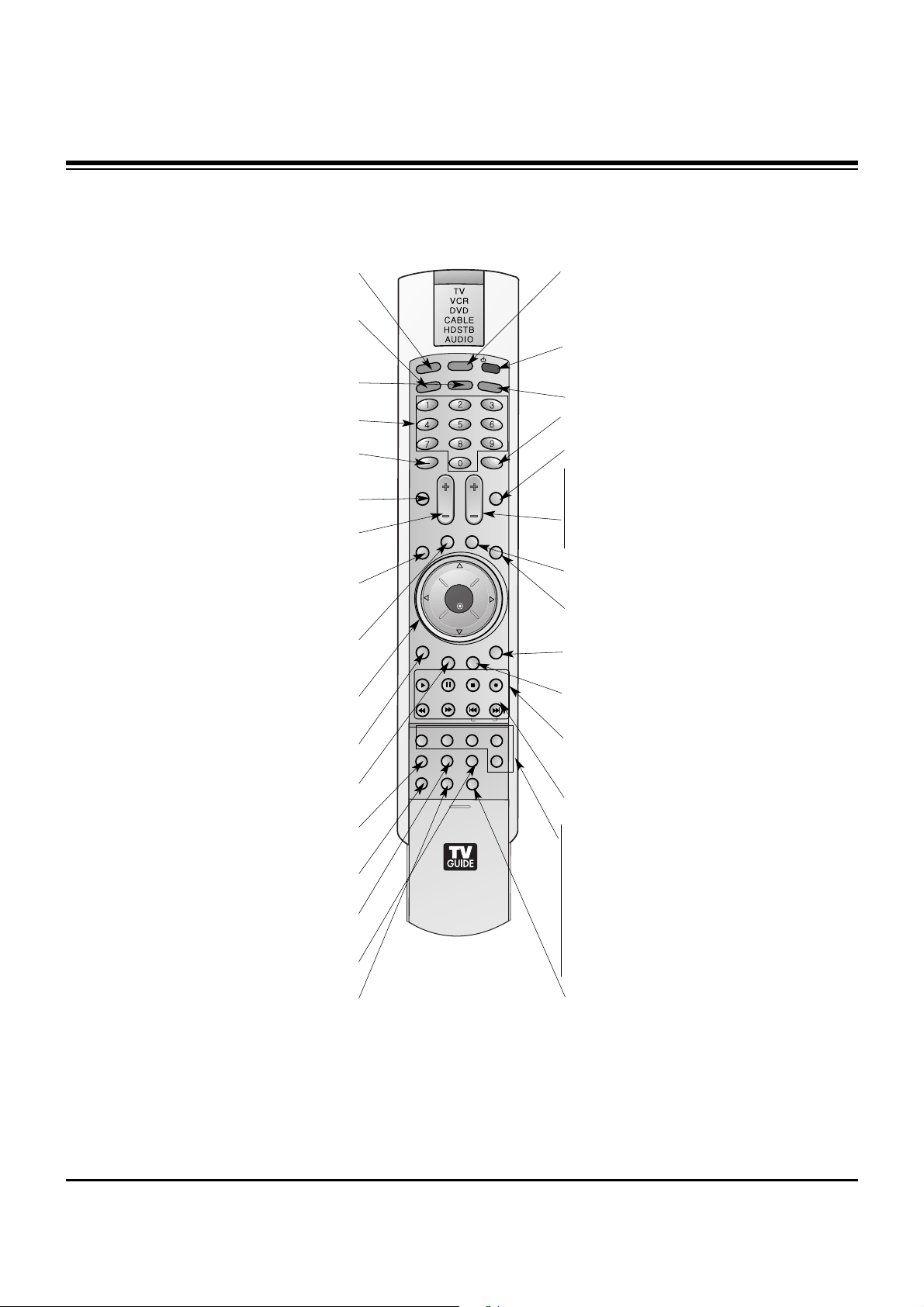
- When using the remote control, aim it at the remote control sensor on the TV.
SKIP
LIGHT
TV/VIDEO
MODE
COMP/RGB/HDMI
MUTE
SURF
VOL CH
PGUP
PGDN
INFO
SAP
RATIO
CC
MENU
TV GUIDE
TIMER
EXIT
PLAY
PAUSE STOP
RECORD
PIP PIPCH- PIPCH+ PIPINPUT
ENTER
SIGNAL SWAP
REW FF
POWER
1394
FLASHBK
VIDEO
SOUND
ADJUST
DAY +
DAY -
FREEZE
ZOOM
LIGHT
Illuminates the remote control buttons.
TV/VIDEO
Selects: DTV, Analog, Video, Front Video,
Component 1-2, RGB-DTV (or RGB-PC),
HDMI/DVI input sources.
COMP/RGB/HDMI
Selects: Component 1-2, RGB-DTV (or RGB-
PC), HDMI/DVI input sources.
NUMBER buttons
DASH
Used to enter a program number for multiple
program channels such as 2-1,2-2,etc.
MUTE
Switches the sound on or off.
VCR/DVD BUTTONS
Control some video cassette recorders or
DVD player ("RECORD" button is not available for DVD player).
RATIO
Changes the aspect ratio.
MODE
Selects the remote operating mode: TV,
VCR, DVD, CABLE, HDSTB or AUDIO.
Select other operating modes, for the
remote to operate external devices.
POWER
Turns your TV or any other programmed
equipment on or off, depending on mode.
1394
SURF
Use to scroll the Surf channel.
CC
Select a closed caption:
Off, CC1~4, Text1~4.
FLASHBK
Tunes to the last channel viewed.
THUMBSTICK (Up/Down/Left/Right/ENTER)
Allows you to navigate the on-screen menus
and adjust the system settings to your pref-
erence.
CHANNEL UP/DOWN
Selects available channels found with EZ
scan.
PAGE UP/PAGE DOWN
Moves from one full set of screen information to the next one.
EXIT
Clears all on-screen displays and returns to
TV viewing from any menu.
TIMER
Lets you select the amount of time before
your TV turns itself off automatically.
VOLUME UP/DOWN
Increases/decreases the sound level.
SAP
Selects MTS sound: Mono, Stereo, and SAP
in Analog mode. Change the audio language
in DTV mode.
MENU
Brings up the main menu to the screen.
INFO
When you watch the TV, displays information
on top of the screen. Not available in
Component 1-2, RGB and HDMI/DVI mode.
TV GUIDE
Brings up the TV Guide On Screen system to
the screen.
PIP
Switches between PIP, POP (Picture-out-ofPicture) and Twin picture modes.
PIPCH-/PIPCH+
Changes to next higher/lower PIP channel.
PIP INPUT
Selects the input source for the sub picture.
SWAP
Exchanges the main/sub images in
PIP/Twin picture mode.
VIDEO
Adjusts the factory preset picture
according to the room.
ADJUST
Adjusts screen position, clock, and
phase in PC mode.
SOUND
Selects the sound appropriate
for the program's character.
SIGNAL
Displays the digital signal strength.
Remote Control Key Functions
Remote Control Key Functions
FREEZE
Freezes the currently-viewed picture. Main pic-
ture is frozen in PIP/Twin picture mode.
ZOOM
Enlarges the main picture size.
DAY+/DAY-
Moves forward of backwards in 24 hour
increments in the Listings Grid.
DESCRIPTION OF CONTROLS
- 7 -
1. Application Object
These instructions are applied to all of the PDP TV, AF-044P.
2. Notes
(1) Because this is not a hot chassis, it is not necessary to use
an isolation transformer. However, the use of isolation
transformer will help protect test equipment.
(2) Adjustments must be done in the correct order.
(3) The adjustments must be performed in the circumstance of
25±5°C of temperature and 65±10% of relative humidity if
there is no specific designation.
(4) The input voltage of the receiver be must kept 110V, 60Hz
when adjusting.
(5) The receiver must be operational for about 15 minutes
prior to the adjustments.
1) After receiving 100% white pattern, the receiver must be
operated prior to adjustment. (Or 9. White Pattern
condition in EZ - Adjust)
2) Enter into White Pattern
- Enter the Ez - Adjust by pressing ADJ Key on Service
Remote Control (S R/C).
- Select the 9. White Pattern using CH +/- Key and
press the Enter(
Y) Key.
Display the 100% Full White Pattern.
[ Set is activated HEAT-RUN without signal generator in
this mode.
If you turn on a still screen more than 20 minutes (Especially
Digital pattern(13 CH), Cross Hatch Pattern), an afterimage
may occur in the black level part of the screen.
3. EPLD Download
(1) Test Equipment: PC, Jig for download
(2) Connect the power of VSC B/D.
(3) Execute download program(iMPACK) of PC.
(4) After executing the hot key on the Programmer, click icon
(5) End after confirming
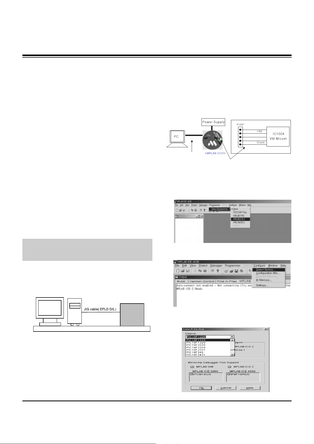
4. Gemstar VBI Micom Download
4-1. Preparation for Adjustment
(1) As shown below, connect the MPLAB ICD2 equipment, PC
and Digital Connector.
(2) Turn on the MPLAB ICD2 POWER Supply.
(3) After turn on the PC and MONITOR, select the ‘MPLAB
IDE’ from the screen.
4-2. Adjustment Sequence
(1) When the program is executed, select the MPLAB ICD2
from Programmer -> Select Programmer .
(2) Select "Configure -> Select Device".
(3) When the "Select Device" window appears, select the
PIC18F1220 from "Device" and press OK.
ADJUSTMENT INSTRUCTIONS
PC
VSC
B/D
<Fig 1> Connection Diagram of EPLD Download
+13V
<Digital Board>
Connect the MPLAB ICD2 and connector of Digital Board
Connect the RS-232 or USB Cable
GND
Data
- 8 -
ADJUSTMENT INSTRUCTIONS
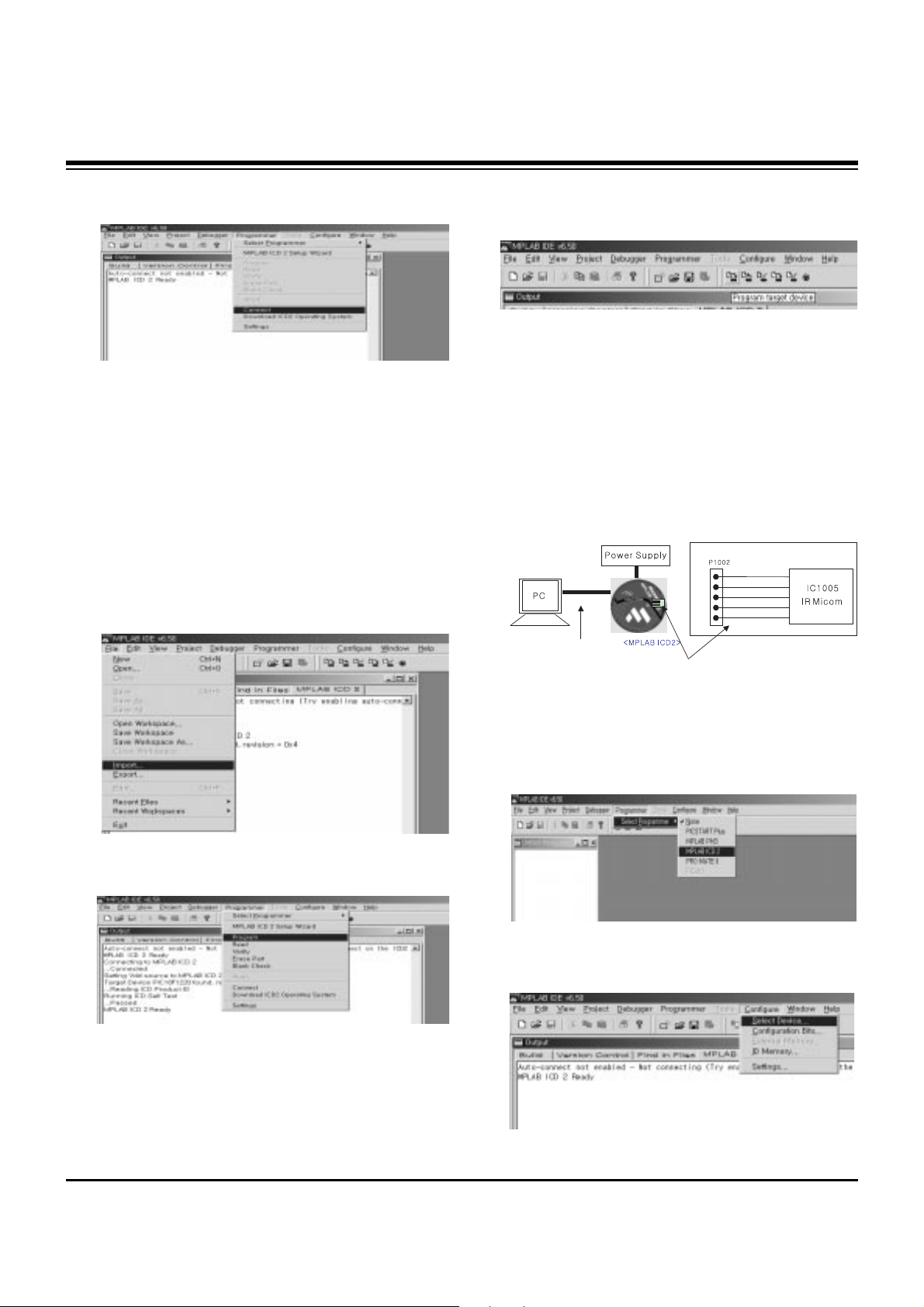
(4) Select "Programmer -> Connect".
When connected with the Micom, the display message on
the Output window appears as below.
(5) Select "File -> Import", select the Work HEX file and open.
(6) Select "Programmer -> Program".
(7) Download is executed and about 5 seconds later, the
"Programming succeeded" message is displayed on the
Output window and the Download process is ended.
(8) The execution of process (6) is convenient when using the
short-cut icon.
5. Gemstar IR Micom Download
5-1. Preparation for Adjustment
(1) As shown below, connect the MPLAB ICD2 equipment, PC
and Digital Connector.
(2) Turn on the MPLAB ICD2 POWER Supply.
(3) After turn on the PC and MONITOR, select the ‘MPLAB
IDE’ from the screen.
5-2. Adjustment Sequence
(1) When the program is executed, select the MPLAB ICD2
from "Programmer -> Select Programmer" .
(2) Select "Configure -> Select Device".
+13V
+5V
GND
Data
Clock
<Digital Board>
Connect the MPLAB ICD2 and connector of Digital Board
Connect the RS-232 or USB Cable
Connecting to MPLAB ICD 2
...Connected
Setting Vdd source to MPLAB ICD 2
Target Device PIC18F1220 found, revision = 0x4
...Reading ICD Product ID
Running ICD Self Test
...Passed
MPLAB ICD 2 Ready
- 9 -
ADJUSTMENT INSTRUCTIONS
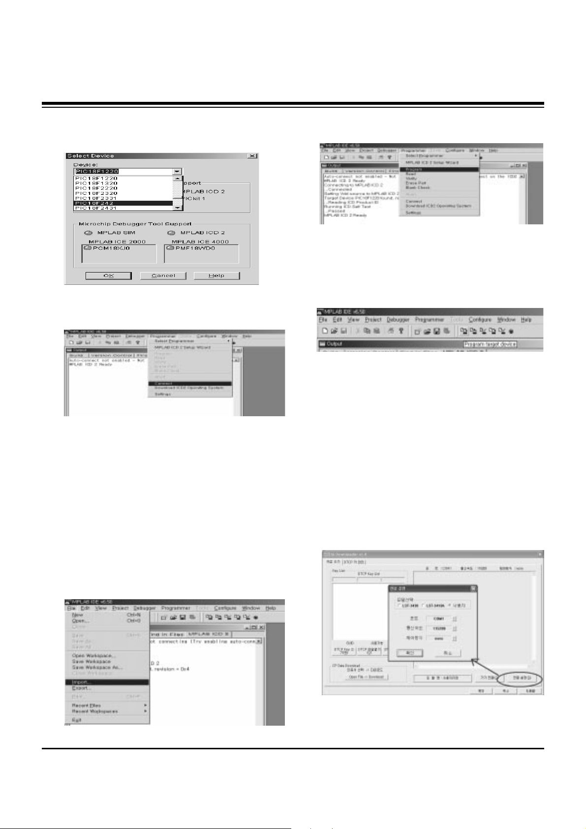
(3) When the "Select Device" window appears, select the
PIC18F242 from "Device" and press OK.
(4) Select "Programmer -> Connect".
When connect with the Micom, the display message on the
Output window appears as below.
(5) Select "File -> Import", select the Work HEX file and open.
(6) Select "Programmer -> Program".
(7) Download is executed and about 3 seconds later, the
"Programming succeeded" message is displayed on the
Output window and the Download process is ended.
(8) The execution of process (6) is convenient when using the
short-cut icon.
6. POD Certificate Download &
IEEE1394(DTCP) Download
6-1. Preparation for Adjustment
(1) Connect the MEMORY JIG and PC.
(2) Turn on the JIG MAIN POWER SWITCH.
(3) After turn on the PC and MONITOR, execute the
‘Certificate Downloader v1.4’ from the screen.
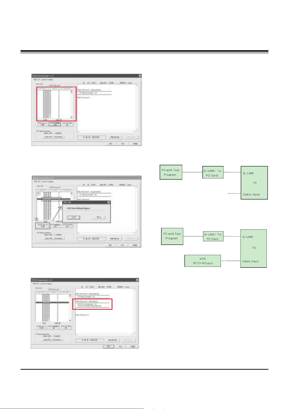
6-2. Adjustment Sequence
(1) After open the ‘Certificate Downloader v1.4’, enter
Connection set and set the as same below.
The port settings are determined by each PC's setup.
Connecting to MPLAB ICD 2
...Connected
Setting Vdd source to MPLAB ICD 2
Target Device PIC18F242 found, revision = 0x7
...Reading ICD Product ID
Running ICD Self Test
...Passed
MPLAB ICD 2 Ready
- 10 -
ADJUSTMENT INSTRUCTIONS
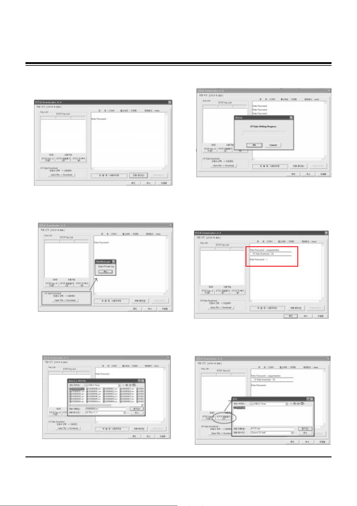
(2) Select ‘Connection’ and SET connected to RS-232C.
(3) After clicking "Enter", confirm that "Enter Password:"
appears.
(4) Click the "OpenFile - Download" button from CP Data
Download, ‘select the Private Key’ appears and click
ENTER.
(5) After clicking ENTER, the ‘opens Private key' window
appears and select the Private key applied to the SET.
The Private Key file name is on the Label of the Digital
Board.
(6) When the Dialog window appears, click OK and the write
work will begin.
(7) When completed, click ‘CP Data Download: OK’
[ When ‘CP Data Download: OK’ does not appear, certificate
has not Download correctly.
SET is rebooted and certificate Download work must be
repeated.
(8) Now, you may begin IEEE1394 (DTCP) Download work.
Select the “DTCP.dat” file by pressing the ‘DTCP File
Open’ button.
- 11 -
ADJUSTMENT INSTRUCTIONS
(9) After opening the ‘DTCP.dat’ file, confirm the key list in the
DTCP Key List window.
(10) Select the desired item of DTCP key List.
When pressing ‘DTCP key writing’ button, the Progress
window will appear.
(11) When completed, “DTCP key Download: OK" will display
in the Terminal window and the SET will reboot
automatically.
[ When process (11) malfunctions, it is not Download.
DTCP Download process start again from (8).
7. Gemstar Operation Confirmation
7-1. Required Test Equipment
(1) PC with Factory Test Program
(2) G-LINK-To-PC Card (Serial GLINK(CN1202))
(3) VBI Inserter (Norpak TES3) - Guide Data Discharge
Equipment
[ In case of without the VBI Inserter(TES3), a VCR may be
used.
7-2. Preparation for Adjustments
(1) In case of with VBI Inserter(TES3): Signal uses Cable
input and set as below.
(2) In case of without VBI Inserter(TES3): VCR uses Cable
input and set as below.
[ Factory Test S/W must be set to "GlinkTo PC Card" ON.
7-3. Adjustment Confirmation Work
(1) Turn on the TV and run Factory Test Program of PC.
[ Program only needs to run once, regardless of set quantity.
(2) Enter the EZ adjust menu by pressing Adjust on the
Service Remote Control (S R/C).
(3) Go to number 1 Gemstar and press Enter.
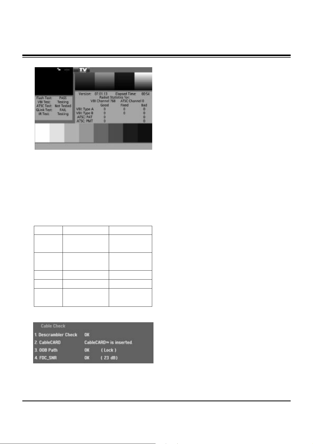
(4) TV set screen will appear as shown.
Input Signal
- 12 -
ADJUSTMENT INSTRUCTIONS
(5) Confrim that VBI Test, Glink Test and IR Test PASS from
the screen.
8. Cable Operation Confirmation
(1) Confirm that the Cable Card is inserted in the slot.
(2) Enter the EZ adjust menu by pressing Adjust on the
Service Remote Control (S R/C).
(3) Go to number 2 Cable Check and press the Right key (
G) .
(4) Confirm items below..
Name
Descrambler
Check
CableCARD
OOB Path
FDC_SNR
Video Signal
Normal
OK
CableCARD
TM
is inserted.
OK(Lock)
OK(20dB above)
Normal Screen
Defective
Not OK
CableCARD
TM
is removed.
Not OK(Unlock)
Not OK(20dB under)
Black Screen
(No Picture)
 Loading...