


Dryers
Use & Care Guide and Installation Instructions
Secadoras
Guía de uso y cuidado e Instrucciones de instalación
Models/Modelos
Electric/Eléctrico 796.8884* Gas/AGas 796.9884*
* = color number, número de color
3828EL4001M |
Sears, Roebuck and Co., Hoffman Estates, IL 60179 U.S.A. |
www.sears.com |

TABLE OF CONTENTS
IMPORTANT SAFETY INSTRUCTIONS
Basic Safety Precautions . . . . . . . . . . . . . . . . . . . .3–6
Special Requirements for Manufactured
or Mobile Homes . . . . . . . . . . . . . . . . . . . . . . . . . . . . .6
FEATURES AND BENEFITS
Key Parts and Components . . . . . . . . . . . . . . . . . . . .7
INSTALLATION INSTRUCTIONS
Key Dimension and Specifications . . . . . . . . . . . . . . .8
Location Requirements . . . . . . . . . . . . . . . . . . . . . . . .8
Choose the Proper Location . . . . . . . . . . . . . . . . . . . .8
Clearances . . . . . . . . . . . . . . . . . . . . . . . . . . . . . . . . .8
Gas Requirements . . . . . . . . . . . . . . . . . . . . . . . . . . .9
Connecting Gas Dryers . . . . . . . . . . . . . . . . . . . . .9, 10
Electrical Requirements . . . . . . . . . . . . . . . . . . . . . . .11
Connecting Electric Dryers . . . . . . . . . . . . . . . . .11, 12
Venting Requirements . . . . . . . . . . . . . . . . . . . . . . . .13
Venting the Dryer . . . . . . . . . . . . . . . . . . . . . . . . .13, 14
Leveling the Dryer . . . . . . . . . . . . . . . . . . . . . . . . . . .15
Reversing the Door Swing . . . . . . . . . . . . . . . . . . . .15
Final Installation Check . . . . . . . . . . . . . . . . . . . . . . .16
HOW TO USE
Control Panel Features . . . . . . . . . . . . . . . . . . . . . . .17
Operating the Dryer . . . . . . . . . . . . . . . . . . . . . . . . . .18
Cycle Guide . . . . . . . . . . . . . . . . . . . . . . . . . . . . . . . .19
Sorting Loads . . . . . . . . . . . . . . . . . . . . . . . . . . . . . .20
Loading the Dryer . . . . . . . . . . . . . . . . . . . . . . . . . . .20
Check the Lint Screen Before Every Load . . . . . . . .20
Time and Status Display . . . . . . . . . . . . . . . . . . . . . .21
Cycle Modifier Buttons . . . . . . . . . . . . . . . . . . . . . . .22
Cycle Option Buttons . . . . . . . . . . . . . . . . . . . . . . . . .23
My Cycle . . . . . . . . . . . . . . . . . . . . . . . . . . . . . . . . . .23
Special Functions . . . . . . . . . . . . . . . . . . . . . . . . . . .24
USER-MAINTENANCE INSTRUCTIONS
Regular Cleaning . . . . . . . . . . . . . . . . . . . . . . . . . . . .25
TROUBLESHOOTING GUIDE
Before Calling for Service . . . . . . . . . . . . . . . . . .26–28
WARRANTY . . . . . . . . . . . . . . . . . . . . . . . . . . . . . . .30
PRODUCT RECORD
In the space below, record the date of purchase, model, and serial number of your product. You will find the model and serial number printed on an identification plate located inside the dryer door. Have these items of information available whenever you contact Sears concerning your product.
Model No.
Date of Purchase
Serial No.
Save these instructions and your sales receipt for future reference.
PROTECTION AGREEMENTS
Master Protection Agreements
Congratulations on making a smart purchase. Your new Kenmore® product is designed and manufactured for years of dependable operation. But like all products, it may require preventive maintenance or repair from time to time. That’s when having a Master Protection Agreement can save you money and aggravation.
The Master Protection Agreement also helps extend the life of your new product. Here’s what the Agreement* includes:
•Parts and labor needed to help keep products operating properly under normal use, not just defects. Our coverage goes well beyond the product warranty. No deductible, no functional failure excluded from coverage—real protection.
•Expert service by a force of more than 10,000 authorized Sears service technicians, which means someone you can trust will be working on your product.
•Unlimited service calls and nationwide service, as often as you want us, whenever you want us.
•“No-lemon” guarantee—replacement of your covered product if four or more product failures occur within twelve months.
•Product replacement if your covered product can’t be fixed.
•Annual Preventive Maintenance Check at your request—no extra charge.
•Fast help by phone—we call it Rapid Resolution.
Phone support from a Sears representative on all products. Think of us as a “talking owner’s manual.”
•Power surge protection against electrical damage due to power fluctuations.
•$250 food loss protection annually for any food spoilage that is the result of mechanical failure of any covered refrigerator or freezer.
•Rental reimbursement if repair of your covered product takes longer than promised.
•10% discount off the regular price of any non-covered repair service and related installed parts.
Once you purchase the Agreement, a simple phone call is all that it takes for you to schedule service. You can call anytime day or night or schedule a service appointment online.
The Master Protection Agreement is a risk free purchase. If you cancel for any reason during the product warranty period, we will provide a full refund, or a prorated refund anytime after the product warranty period expires.
Purchase your Master Protection Agreement today!
Some limitations and exclusions apply.
For prices and additional information in the U.S.A. call 1-800-827-6655.
*Coverage in Canada varies on some items.
For full details call Sears Canada at 1-800-361-6665.
Sears Installation Service
For Sears professional installation of home appliances, garage door openers, water heaters, and other major home items, in the U.S.A. or Canada, call 1-800-4-MY-HOME®.
2

SAFETY MESSAGES
We have provided many important safety messages in this manual and on your appliance. Always read and obey all safety messages.
This is the safety alert symbol.
This symbol alerts you to potential hazards that can result in property damage and/or serious bodily harm or death.
All safety messages will follow the safety alert symbol and either the word DANGER or WARNING. These words mean:
 DANGER
 WARNING
Failure to follow these safety instructions may result in property damage and/or serious bodily harm or death.
Failure to follow these safety instructions may result in property damage and/or serious bodily harm or death.
All safety messages will tell you what the potential hazard is, tell you how to reduce the chance of injury, and tell you what can happen if the instructions are not followed.
IMPORTANT SAFETY INSTRUCTIONS
 WARNING
READ ALL INSTRUCTIONS BEFORE USE
For your safety, the information in this manual must be followed to minimize the risk of fire or explosion, electric shock, or to prevent property damage, personal injury, or loss of life.
To reduce the risk of fire, electric shock, or injury to persons when using this appliance, follow basic precautions, including the following:
•Read all instructions before using the dryer.
•Before use, the dryer must be properly installed as described in this manual.
•Do not place items exposed to cooking oils in your dryer. Items contaminated with cooking oils may contribute to a chemical reaction that could cause a load to catch fire.
•Do not dry articles that have been previously cleaned in, washed in, soaked in, or spotted with gasoline, dry-cleaning solvents, or other flammable or explosive substances, as they give off vapors that could ignite
or explode.
•Do not reach into the dryer if the drum or any other part is moving.
•Do not repair or replace any part of the dryer or attempt any servicing unless specifically recommended in this Use and Care Guide or in published user-repair instructions that you understand and have the skills
to carry out.
•Do not tamper with the controls.
•Before the dryer is removed from service or discarded, remove the door to the drying compartment.
•Do not allow children to play on or in the dryer. Close supervision of children is necessary when the dryer is used near children.
•Do not use fabric softeners or products to eliminate static unless recommended by the manufacturer of the fabric softener or product.
•Do not use heat to dry articles containing foam rubber or similarly textured rubber-like materials.
•Keep the area around the exhaust opening and adjacent surrounding areas free from the accumulation of lint, dust, and dirt.
•The interior of the dryer and exhaust vent should be cleaned periodically by qualified service personnel.
•Do not install or store the dryer where it will be exposed to the weather.
•Always check the inside of the dryer for foreign objects.
•Clean the lint screen before or after each load.
3

IMPORTANT SAFETY INSTRUCTIONS
 WARNING
For your safety, the information in this manual must be followed to minimize the risk of fire or explosion, electric shock, or to prevent property damage, personal injury, or loss of life.
•Do not store or use gasoline or any other liquid with flammable vapors in the vicinity of this appliance or any other appliances.
•Installation and service must be performed by a qualified installer, service agency, or the gas supplier.
WHAT TO DO IF YOU SMELL GAS:
1.Do not try to light a match or cigarette, or turn on any gas or electrical appliance.
2.Do not touch any electrical switches. Do not use any phone in your building.
3.Clear the room, building, or area of all occupants.
4.Immediately call your gas supplier from a neighbor’s phone. Follow the gas supplier’s instructions carefully.
5.If you cannot reach your gas supplier, call the fire department.
CALIFORNIA SAFE DRINKING WATER AND TOXIC ENFORCEMENT ACT
This act requires the governor of California to publish a list of substances known to the state to cause cancer, birth defects, or other reproductive harm and requires businesses to warn customers of potential exposure to such substances.
Gas appliances can cause minor exposure to four of these substances, namely benzene, carbon monoxide, formaldehyde, and soot, caused primarily by the incomplete combustion of natural gas or LP fuels.
Properly adjusted dryers will minimize incomplete combustion. Exposure to these substances can be minimized further by properly venting the dryer to the outdoors.
 WARNING
To reduce the risk of fire, electric shock, or injury to persons when using this appliance, follow basic precautions, including the following:
•Properly ground dryer to conform with all governing codes and ordinances. Follow details in the installation instructions. Electrical shock can result if the dryer is not properly grounded.
•Before use, the dryer must be properly installed as described in this manual. Electrical shock can result if the dryer is not properly grounded.
•Install and store the dryer where it will not be exposed to temperatures below freezing or exposed to the weather.
•All repairs and servicing must be performed by an authorized servicer unless specifically recommended in this Owner’s Guide. Use only
authorized factory parts. Failure to follow this warning can cause serious injury, fire, electrical shock, or death.
•To reduce the risk of electric shock, do not install the dryer in humid spaces. Failure to follow this warning can cause serious injury, fire, electrical shock, or death.
•Connect to a properly rated, protected, and sized power circuit to avoid electrical overload. Improper power circuit can melt, creating an electrical shock and/or a fire hazard.
•Remove all packing items and dispose of all shipping materials properly. Failure to do so can result in death, explosion, fire, or burns.
•Place dryer at least 18 in. above the floor for a garage installation. Failure to do so can result in death, explosion, fire, or burns.
•Keep all packaging from children. Packaging material can be dangerous for children. There is a risk of suffocation.
4

IMPORTANT SAFETY INSTRUCTIONS
 WARNING
SAFETY INSTRUCTIONS FOR INSTALLATION
Exhaust/Ducting:
•Gas dryers MUST be exhausted to the outside.
Failure to follow these instructions can result in fire or death.
•The dryer exhaust system must be exhausted to the outside of the dwelling. If the dryer is not exhausted outdoors, some fine lint and large amounts of moisture will be expelled into the laundry area. An accumulation of lint in any area of the home can create a health and fire hazard.
•Use only rigid metal or flexible metal 4-in. diameter ductwork inside the dryer cabinet or for exhausting to the outside. Use of plastic or other combustible ductwork can cause a fire. Punctured ductwork can cause a fire if it collapses or becomes otherwise restricted in use or during installation.
•Ductwork is not provided with the dryer, and you should obtain the necessary ductwork locally. The end cap should have hinged dampers to prevent backdraft when the dryer is not in use. Failure to follow these instructions can result in fire or death.
•The exhaust duct must be 4-in. (10 cm) in diameter with no obstructions. The exhaust duct should be kept as short as possible. Make sure to clean any old ducts before installing your new dryer. Failure to follow these instructions can result in fire or death.
•Rigid or semi-rigid metal ducting is recommended for use between the dryer and the wall. In special installations when it is impossible to make a connection with the above recommendations, a ULlisted flexible metal transition duct may be used between the dryer and wall connection only. The use of this ducting will affect drying time. Failure to follow these instructions can result in fire or death.
•DO NOT use sheet metal screws or other fasteners which extend into the duct; they can catch lint and reduce the efficiency of the exhaust system. Secure all joints with duct tape. For complete details, follow the Installation Instructions. Failure to follow these instructions can result in fire or death.
 WARNING
SAFETY INSTRUCTIONS FOR CONNECTING ELECTRICITY
To reduce the risk of fire, electric shock, or injury to persons when using this appliance, follow basic precautions, including the following:
•Do not, under any circumstances, cut or remove the ground prong from the power cord. To prevent personal injury or damage to the dryer, the electrical power cord must be plugged into a properly grounded outlet.
•For personal safety, this dryer must be properly grounded. Failure to do so can result in electrical shock or injury.
•Refer to the installation instructions in this manual for specific electrical requirements for your model. Failure to follow these instructions can create an electrical shock hazard and/or a fire hazard.
•This dryer must be plugged into a properly grounded outlet. Electrical shock can result if the dryer is not properly grounded. Have the wall outlet and circuit checked by a qualified electrician to make sure the outlet is properly grounded. Failure to follow these instructions can create an electrical shock hazard and/or a fire hazard.
•The dryer should always be plugged into its own individual electrical outlet which has a voltage rating that matches the rating plate. This provides the best performance and also prevents overloading house wiring circuits which could cause a fire hazard from overheated wires.
•Never unplug your dryer by pulling on the power cord. Always grip plug firmly and pull straight out from the outlet. The power cord can be damaged, resulting in a risk of fire and electrical shock.
•Immediate repair or replace all power cords that have become frayed or otherwise damaged. Do not use a cord that shows cracks or abrasion damage along its length or at either end. A damaged power cord can melt, creating an electrical shock and/or a fire hazard.
•When installing or moving the dryer, be careful not to pinch, crush, or damage the power cord. This will prevent injury and prevent damage to the dryer from fire and electrical shock.
5

IMPORTANT SAFETY INSTRUCTIONS
GROUNDING INSTRUCTIONS
 WARNING
For your safety, the information in this manual must be followed to minimize the risk of fire or explosion, electric shock, or to prevent property damage, personal injury, or loss of life.
This appliance must be grounded. In the event of malfunction or breakdown, grounding will reduce the risk of electric shock by providing a path of least resistance for electric current. This appliance must be equipped with a cord having an equipmentgrounding conductor and a grounding plug. The plug must be plugged into an appropriate outlet that is properly installed and grounded in accordance with all local codes and ordinances.
Improper connection of the equipment-grounding conductor can result in a risk of electric shock. Check with a qualified electrician or service person if you are in doubt as to whether the appliance is properly grounded.
Do not modify the plug provided with the appliance. If it does not fit the outlet, have a proper outlet installed by a qualified electrician.
This appliance must be connected to a grounded metal, permanent wiring system or an equipment grounding conductor must be run with the circuit conductors and connected to the equipment grounding terminal or lead on the appliance.
Electrical shock can result if the dryer is not properly grounded.
SPECIAL REQUIREMENTS FOR MANUFACTURED OR MOBILE HOMES
 WARNING
To reduce the risk of fire, electric shock, or injury to persons when using this appliance, follow basic precautions, including the following:
•Any installation in a manufactured or mobile home must comply with the Manufactured Home Construction and Safety Standards Title 24 CFR, Part 32-80 or Standard CAN/CSA0Z240 MH and local codes and ordinances. If you are uncertain whether your proposed installation will comply with these standards, please contact a service and installation professional for assistance.
•A gas dryer must be permanently attached to the floor.
•A 4-wire connection is required for all manufactured or mobile home installations, as well as all new construction after January 1, 1996. A 4-wire connection must be used where local codes do not permit grounding through the neutral wire. Failure to do so can result in fire, explosion, or death.
•To reduce the risk of combustion and fire, the dryer must be vented to the outside.
•DO NOT vent the dryer under a manufactured home or mobile home.
•Electric dryers may be vented to the outside using the back, left, right, or bottom panel.
•Gas dryers may be vented to the outside using
the back, left, or bottom panel. Gas dryers may not be vented to the outside using the right side panel because of the burner housing.
•The dryer exhaust duct must be affixed securely to the manufactured or mobile home structure, and the exhaust duct must be made of a material that will resist fire and combustion. It is recommended that you use
a rigid or flexible metal duct.
•DO NOT connect the dryer exhaust duct to any other duct, vent, chimney, or other exhaust duct.
•Make sure the dryer has adequate access to outside fresh air to ensure proper operation. The opening for outside fresh air must be at least 25 in2 (163 cm2).
•It is important that the clearance of the duct from any combustible construction be at least 2 in. (5 cm), and when venting the dryer to the outdoors, the dryer can be installed with a clearance of 1 in. (2.5 cm) at the sides and back of the dryer.
•Please be aware that venting materials are not supplied with the dryer. You should obtain the venting materials necessary for proper installation.
SAVE THESE INSTRUCTIONS
6

FEATURES AND BENEFITS
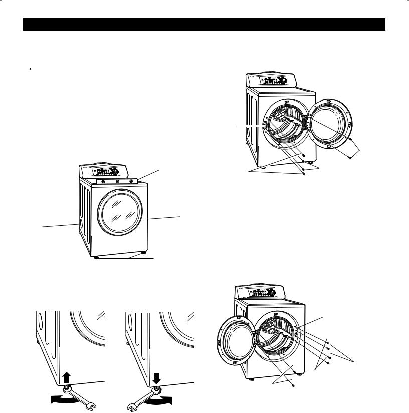
KEY PARTS AND COMPONENTS |
|
A |
|
There are several important components that are |
B |
|
|
referenced in this manual. |
C |
||
|
A
Rotate the Cycle Selector Knob to select the desired dry cycle. Add cycle options or adjust settings with the touch of a button. Press the Cycle Selector Knob to start the selected dry cycle.
B TIME AND STATUS DISPLAY
The easy-to-read LED display shows cycle options and information and provides cycle status during operation.
C
(Duct Blockage Sensing System)
The Check Vent (Duct blockage sensing system) detects and alerts you to blockages in the exhaust system that reduce airflow from the dryer. D Maintaining clean exhaust system ducts
improves operating efficiency and helps minimize service calls, saving you money.
D
STEEL DRUM WITH DRUM LIGHT
The ultra-large stainless steel drum offers superior durability. The drum is equipped with a light that illuminates when the dryer door is open and turns off when the door is closed.
E
Wide-opening, see-through glass door provides easy access for loading and unloading. Door swing can be reversed to adjust for installation location.
F
Front-mounted lint screen allows for easy access and cleaning between loads.
G
F E
G
Terminal Block |
Power Cord |
Access Panel |
Location |
(Electric Models) |
(Gas Models) |
Four leveling feet (two in front, and two in back) adjust to improve dryer stability on uneven floors.
H |
H |
Use the drying rack with the RACK DRY cycle option. |
|
The drying rack allows items such as sweaters, |
|
delicates, and gym shoes to be placed |
|
in a flat position for drying. |
|
For special installation applications, the following |
|
kits are available. Go to www.searspartsdirect.com, |
|
or call 1-800-4-MY-HOME® for ordering information. |
|
I |
|
I |
|
This LP conversion kit contains all required parts |
|
|
to change the dryer gas connections from Natural |
|
|
Gas (NG) to Liquefied Propane Gas (LP). |
|
J |
|
J |
|
The side vent kit contains the necessary parts |
|
|
to change the dryer from a rear vent to a side |
|
|
vent location. |
7 |
|
|
Exhaust Duct
Outlet
Gas Connection
Location
Rear of Dryer
(Gas Models)
|
|
INSTALLATION INSTRUCTIONS |
|
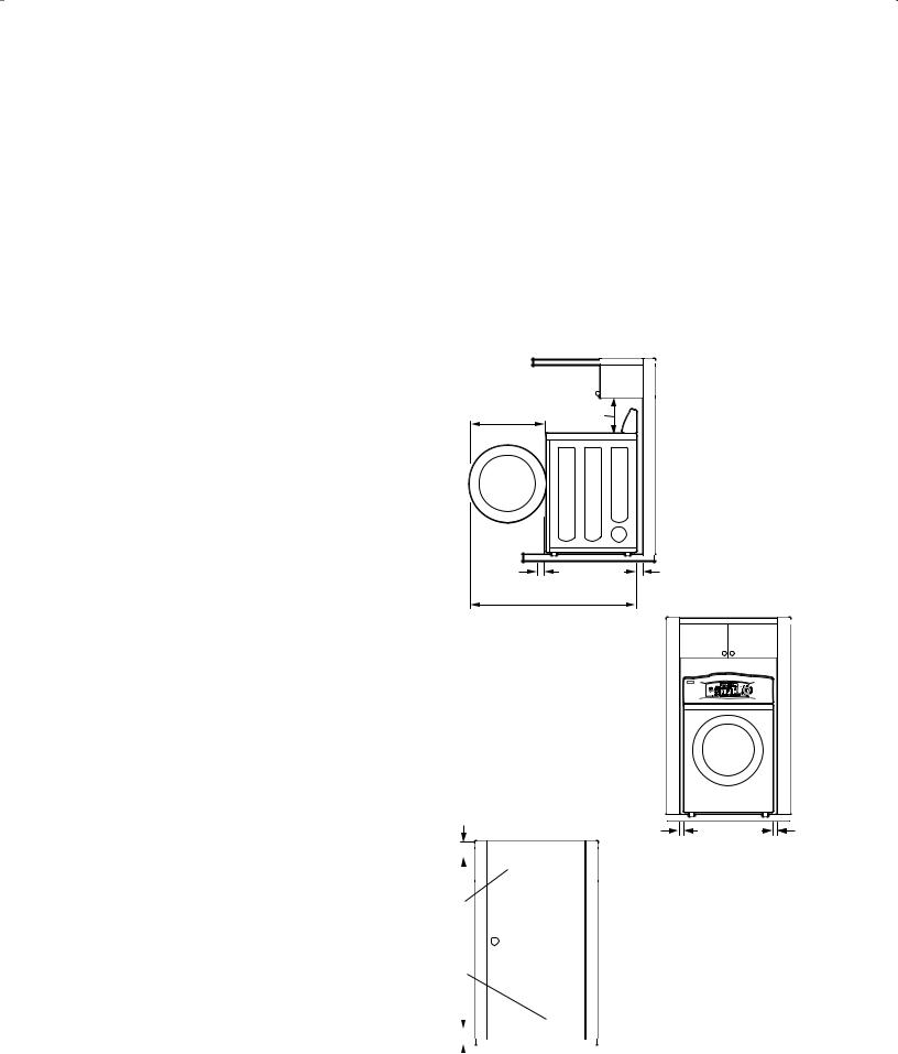
KEY DIMENSIONS AND SPECIFICATIONS |
|||
|
|
|
|
|
Description |
Dryer (Gas and Electric) |
|
|
|
|
|
|
Electrical Requirements |
Please refer to the rating label. |
|
|
Gas Requirements* NG: |
6–8 in. WC |
|
|
Gas Requirements* LP: |
10–13 in. WC |
|
|
|
|
|
|
Dimensions |
27"(W) X 30"(D) X 38 11/16"(H), 50" (D with door open) |
|
|
|
68.6 cm (W) X 76.1 cm (D) X 98.3 cm (H), 127 cm (D with door open) |
|
|
|
|
|
|
Net Weight |
126 lb. (57.2 kg) |
|
|
|
|
|
|
Drying Capacity |
IEC 7.3 cu. ft. (22.5 lbs./10.2 kg) |
|
|
|
|
|
*Gas Models only.
LOCATION REQUIREMENTS |
|
|
|
|
|
IMPORTANT: |
20" |
18" |
|
|
|
Read all installation instructions completely before |
(50.8 cm) |
|
|
||
(45.7 cm) |
|
|
|||
installing and operating your dryer! |
|
|
|
|
|
It is important that you review this entire manual before |
|
|
|
|
|
installing and using your dryer. Detailed instructions |
|
|
|
|
|
concerning electrical connections, gas connections, |
|
|
|
|
|
and exhaust requirements are provided on the |
|
|
|
|
|
following pages. |
|
|
|
|
|
CHOOSE THE PROPER LOCATION |
4" |
|
4" |
|
|
• Store and install the dryer where it will not be exposed |
30" |
(10 cm) |
|
||
(10 cm) |
|
||||
|
to temperatures below freezing or exposed to outdoor |
(76.1 cm) |
|
|
|
|
|
|
|
||
|
weather conditions. |
|
50" |
|
|
• |
Choose a location with a solid, level floor. |
|
|
|
|
(127 cm) |
|
|
|||
• |
If the dryer is being installed in a garage, place the |
|
|
|
|
|
dryer at least 18 in. (46 cm) above the floor. |
|
|
|
|
• Properly ground the dryer to conform with all governing |
|
|
|
|
|
|
codes and ordinances. |
|
|
|
|
• |
To reduce the risk of electric shock, do not install |
|
|
|
|
|
the dryer in damp or wet locations. |
|
|
|
|
IMPORTANT: If you are installing your dryer in a |
|
|
|
|
|
manufactured or mobile home, please refer to the |
3" |
|
|
|
|
section Special Requirements for Manufactured |
|
|
|
||
(7.6 cm) |
1" |
|
1" |
||
or Mobile Homes on page 6. |
|
||||
|
(2.5 cm) |
27" |
(2.5 cm) |
||
CLEARANCES |
|
||||
|
|
(68.6 cm) |
|
||
• Most installations require a minimum 5 1/2 in. |
|
|
|
|
|
|
|
|
|
|
|
|
|
|
|
|
|
|
|
|
|
||
|
(14 cm) clearance behind the dryer for |
|
|
|
|
|
|
|
|
|
Additional Instructions for |
|
|
|
|
|
|
|
|
|
|
||
|
|
|
|
|
|
|
|
|
|
||
|
the exhaust ducting. |
48 in.2 |
|
|
|
|
|
||||
|
|
|
|
|
|
closet installations: |
|||||
• Allow minimum clearances of at least 1 in. |
(310 cm) |
|
|
|
|
|
|||||
|
|
|
|
|
• The closet door must allow |
||||||
|
(2.5 cm) on the sides and back to minimize |
|
|
|
|
|
|
|
|
|
|
|
vibration and noise. |
34 in.2 |
|
|
|
|
|
for sufficient airflow. Refer to |
|||
|
|
|
|
|
|
the diagram to the left for |
|||||
• Allowing additional clearance for installation |
(155 cm) |
|
|
|
|
|
|||||
|
|
|
|
|
minimum vent opening |
||||||
|
|
|
|
|
|
|
|
|
|||
|
and servicing is recommended. |
|
|
|
|
|
|
|
|
|
requirements. Alouvered |
• |
Be sure to allow for wall, door, or floor moldings |
|
|
|
|
|
|
|
|
|
door is also acceptable. |
|
|
|
|
|
|
|
|
|
|||
|
|
|
|
|
|
|
|
|
|||
|
|
|
|
|
|
|
|
|
• Make sure that there is |
||
|
that may increase the required clearances. |
|
|
|
|
|
|
|
|
|
|
|
|
|
|
|
|
|
|
|
|
||
|
|
|
|
|
|
|
|
|
|
||
• |
Allow at least 21 in. (53.3 cm) in front of the dryer |
|
|
|
|
|
Closet Door Vent |
at least 18 in. (46 cm) of |
|||
|
|
|
|
|
|||||||
3" |
|
|
Requirements |
clearance above the dryer. |
|||||||
|
to open the door. |
|
|
||||||||
|
(7.6 cm) |
|
|
|
|
|
|||||
8
INSTALLATION INSTRUCTIONS
GAS REQUIREMENTS (GAS MODELS ONLY)
CONNECTING GAS DRYERS
 WARNING: To reduce the risk of fire, electric shock, or injury to persons when using this appliance, follow basic precautions, including the following:
•Gas supply requirements:
As shipped from the factory, this dryer is configured for use with (NG) natural gas. It can be converted for use with LP (Liquefied Propane) gas. Gas pressure must not exceed 8-in. water column for (NG), or 13-in. water column for (LP).
•A qualified service or gas company technician must connect the dryer to the gas service. Failure to do so can result in fire, explosion, or death.
•Isolate the dryer from the gas supply system by closing its individual manual shutoff valve during any pressure testing of the gas supply. Failure to do so can result in fire, explosion, or death.
•Supply line requirements:
Your laundry room must have a rigid gas supply line to your dryer. In the United States, an individual manual shutoff valve MUST be installed within at least 6 ft. (1.8 m) of the dryer, in accordance with the National Fuel Gas Code ANSI Z223.1. A 1/8-in. NPT pipe plug must be installed. Failure to do so can result in fire, explosion, or death.
•If using a rigid pipe, the rigid pipe should be 1/2-in. IPS. If acceptable under local codes and ordinances and when acceptable to your gas supplier, 3/8-in. approved tubing may be used where lengths are less than 20 ft. (6.1 m). Larger tubing should be used for lengths in excess of 20 ft. (6.1 m). Failure to do so can result in fire, explosion, or death.
•Connect the dryer to the type of gas shown on the nameplate. Failure to do so can result in fire, explosion, or death.
•To prevent contamination of the gas valve, purge the gas supply of air and sediment before connecting the gas supply to the dryer. Before
tightening the connection between the gas supply and the dryer, purge remaining air until the odor of gas is detected. Failure to do so can result in fire, explosion, or death.
•DO NOT use an open flame to inspect for gas leaks. Use a noncorrosive leak detection fluid. Failure to do so can result in fire, explosion, or death.
•Use only a new AGAor CSA-certified gas supply line with flexible stainless steel connectors. Failure to do so can result in fire, explosion, or death.
•Securely tighten all gas connections. Failure to do so can result in fire, explosion, or death.
•Use Teflon® tape or a pipe-joint compound that is insoluble in Liquefied Petroleum (LP) gas on all pipe threads. Failure to do so can result in fire, explosion, or death.
•DO NOT attempt any disassembly of the dryer; any disassembly requires the attention and tools of an authorized and qualified service person or company.
Failure to do so can result in fire, explosion, or death.
Electrical Requirements for Gas Models Only
•Do not, under any circumstances, cut or remove the third (ground) prong from the power cord. Failure to follow this warning can result in fire, explosion, or death.
•For personal safety, this dryer must be properly grounded. Failure to follow this warning can result in fire, explosion, or death.
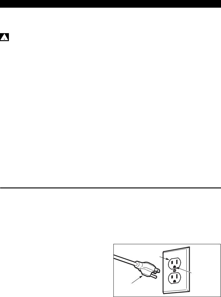
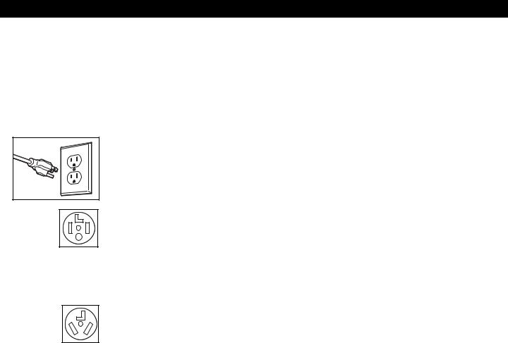
•The power cord of this dryer is equipped with a 3-prong (grounding) plug which mates with a standard 3-prong (grounding) wall outlet to minimize the possibility of electric shock hazard from this appliance. Failure to follow this warning can result in fire, explosion, or death.
•This dryer must be plugged into a 120-VAC, 60-Hz. grounded outlet protected by a 15-ampere fuse or circuit breaker. Failure to follow this warning can result in fire, explosion, or death.
•Where a standard 2-prong wall outlet is encountered, it is your personal responsibility and obligation to have it replaced with a properly grounded 3-prong wall outlet. Failure to follow this warning can result in fire, explosion, or death.
3-prong grounding type wall receptacle 
Ensure proper ground exists
3-prong before use. grounding
plug
9
INSTALLATION INSTRUCTIONS
CONNECTING GAS DRYERS (cont.)
 WARNING: To reduce the risk of fire, electric shock, or injury to persons when using this appliance, follow basic precautions, including the following:
•Installation and service must be performed by a qualified installer, service agency, or the gas supplier. Failure to do so can result in fire, explosion, or death.
•Use only a new stainless steel flexible connector and a new AGA-certified connector. Failure to do so can result in fire, explosion, or death.
•Agas shutoff valve must be installed within 6 ft. (1.8 m) of the dryer. Failure to do so can result in fire, explosion, or death.
•The dryer is configured for Natural Gas when shipped from the factory. Make sure that the dryer is equipped with the correct burner nozzle for the type of gas being used (Natural Gas or Liquefied Petroleum). Failure to do so can result in fire, explosion, or death.
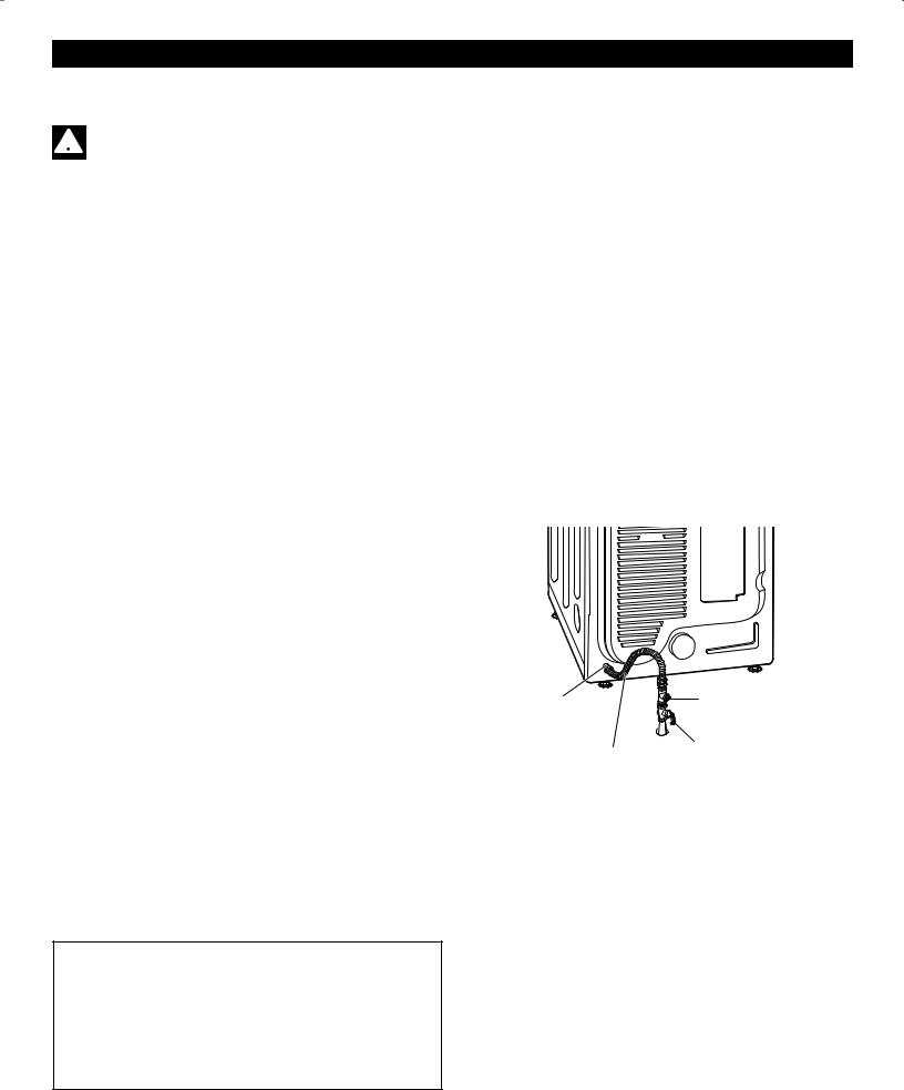
Connecting the Gas Supply
NOTE: This dryer is configured from the factory set for Natural Gas (NG). If dryer is to be used with LP gas, it must be converted by a qualified service technician.
1.Make sure that the gas supply to the laundry room is turned OFF and the dryer is unplugged. Confirm that the type of gas available in your laundry room is appropriate for the dryer.
2.Remove the shipping cap from the gas fitting at the back of the dryer. Be careful not to damage the threads of the gas connector when removing the shipping cap.
3.Connect the dryer to your laundry room’s gas supply using a new flexible stainless steel connector with a 3/8-in. NPT fitting.
NOTE: DO NOT use old connectors.
4.Securely tighten all connections between the dryer and your laundry room’s gas supply.
5.Turn on your laundry room’s gas supply.
6.Check all pipe connections (both internal and external) for gas leaks with a noncorrosive leak-detection fluid.
7.Proceed to Venting Requirements on page 13.
•If necessary, the correct nozzle (for the LP nozzle kit, order part number 4948EL4002B) should be installed by a qualified technician and the change should be noted on the dryer. Failure to do so can result in fire, explosion, or death.
•All connections must be in accordance with local codes and regulations. Failure to do so can result in fire, explosion, or death.
•Gas dryers MUST exhaust to the outdoors. Failure to do so can result in fire, explosion, or death.
3/8" NPT Gas |
1/8" NPT Pipe Plug |
|
|
Connection |
|
Gas Supply
AGA/CSA-Certified Shutoff Valve
Stainless Steel
Flexible Connector
High-Altitude Installations
The BTU rating of this dryer is AGA-certified for elevations below 10,000 feet.
If your gas dryer is being installed at an elevation above 10,000 feet, it must be derated by a qualified technician or gas supplier.
10
INSTALLATION INSTRUCTIONS
ELECTRICAL REQUIREMENTS
CONNECTING ELECTRIC DRYERS
 WARNING: To help prevent fire, electric shock, serious injury, or death, the wiring and grounding must conform to the latest edition of the National Electrical Code, ANSI/NFPA 70 and all applicable local regulations. Please contact
a qualified electrician to check your home’s wiring and fuses to ensure that your home has adequate electrical power to operate the dryer.
Special Electrical Requirements for Mobile or Manufactured Homes
 WARNING: To reduce the risk of fire, electric shock, or injury to persons when using this appliance, follow basic precautions, including the following:
•Any installation in a manufactured or mobile home must comply with the Manufactured Home Construction and Safety Standards Title 24 CFR, Part 32-80 or Standard CAN/CSA0Z240 MH and local codes and ordinances.
•A 4-wire connection is required for all mobile and manufactured home installations, as well as all new construction after January 1, 1996. Failure to do so can result in fire, explosion, or death.
Electrical Requirements for
Electric Models Only
 WARNING: To reduce the risk of fire, electric shock, or injury to persons when using this appliance, follow basic precautions, including the following:
•This dryer must be connected to a grounded metal, permanent wiring system, or an equipmentgrounding conductor must be run with the circuit conductors and connected to the equipmentgrounding terminal or lead on the dryer. Failure
to do so can result in fire, explosion, or death.
•The dryer has its own terminal block that must be connected to a separate 240 VAC, 60-Hertz, singlephase circuit, fused at 30 amperes. The circuit must be fused on both sides of the line. ELECTRICAL SERVICE FOR THE DRYER SHOULD BE OF THE MAXIMUM RATE VOLTAGE LISTED ON THE NAMEPLATE. DO NOT CONNECT DRYER TO 110-, 115-, OR 120-VOLT CIRCUIT. Heating elements are available for field installation in dryers which are to be connected to an electrical service of a different voltage than that listed on the rating plate. Failure to follow these instructions can result in fire, explosion, or death.
•If branch circuit to dryer is 15 ft. (4.5 m) or less in length, use UL (Underwriters Laboratories) listed No.-10 AWG wire (copper wire only), or as required by local codes. If over 15 ft. (4.50 m), use UL-listed No.-8 AWG wire (copper wire only), or as required by local codes. Allow sufficient slack in wiring so dryer can be moved from its normal location when necessary. Failure to do so can result in fire, explosion, or death.
•The power cord (pigtail) connection between wall receptacle and dryer terminal block IS NOT supplied with the dryer. Type of pigtail and gauge of wire must conform to local codes and with instructions on the following pages. Failure to follow these instructions can result in fire, explosion, or death.
•A 4-wire connection is required for all new construction after January 1, 1996. A 4-wire connection must be used where local codes do not permit grounding through the neutral wire.
Failure to do so can result in fire, explosion, or death.
11
INSTALLATION INSTRUCTIONS
CONNECTING ELECTRIC DRYERS (cont.)
 WARNING
•Connect the power cord to the terminal block. Each colored wire should be connected to same color screw. Wire color indicated on manual is connected to the same color screw in block. Failure to follow these instructions may result in a short or overload.
•Grounding through the neutral conductor is prohibited for: (1) new branch-circuit installations,
(2) mobile homes, (3) recreational vehicles, and (4) areas where local codes prohibit grounding through the neutral conductor.
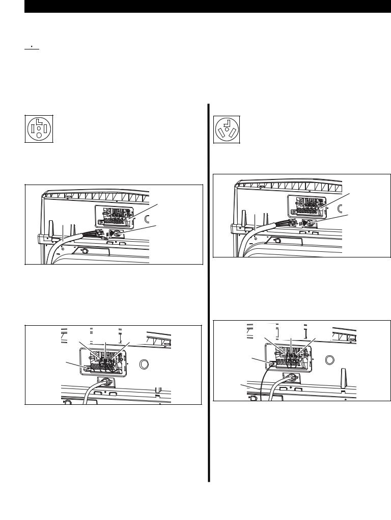
Four-Wire Power Cord
• A 4-wire connection is required for all mobile and manufactured home installations, as well as all new construction after January 1, 1996.
•A UL-listed strain relief is required.
•Use a 30-amp, 240-volt, 4-wire, UL-listed power cord with #10 AWG-minimum copper conductor and closed loop or forked terminals with upturned ends.
UL-Listed |
Terminal |
|
Block |
||
4-Wire |
||
|
||
Power Cord |
|
|
|
UL-Listed |
|
|
Strain |
|
|
Relief |
1.Remove the terminal block access cover on the upper back of the dryer.
2.Install a UL-listed strain relief into the power cord through-hole.
3.Thread a 30-amp, 240-volt, 4-wire, UL-listed power cord with #10 AWG-minimum copper conductor through the strain relief.
Hot |
Neutral |
Hot |
(Black) |
(White) |
(Red) |
Ground |
|
|
Screw |
|
Power Cord |
|
|
|
|
|
Ground Wire |
4.Transfer the dryer’s ground wire from behind the green ground screw to the center screw of the terminal block.
5.Attach the two hot leads of the power cord to the outer terminal block screws.
6.Attach the white neutral wire to the center screw of the terminal block.
7.Attach the power cord ground wire to the green ground screw.
8.TIGHTEN ALL SCREWS SECURELY.
9.Reinstall the terminal block access cover.
Three-Wire Power Cord
• A 3-wire connection is NOT permitted on new construction after January 1, 1996.
•A UL-listed strain relief is required.
•Use a 30-amp, 240-volt, 3-wire, UL-listed power cord with #10 AWG-minimum copper conductor and closed loop or forked terminals with upturned ends.
UL-Listed |
Terminal |
|
Block |
||
3-Wire |
||
|
||
Power Cord |
|
|
|
UL-Listed |
|
|
Strain |
|
|
Relief |
1.Remove the terminal block access cover on the upper back of the dryer.
2.Install a UL-listed strain relief into the power cord through-hole.
3.Thread a 30-amp, 240-volt, 3-wire, UL-listed power cord with #10 AWG-minimum copper conductor through the strain relief.
Hot |
Neutral |
Hot |
(Black) |
(White) |
(Red) |
Ground |
|
|
Screw |
|
|
Ground |
|
|
Wire |
|
|
4.Attach the two hot leads of the power cord to the outer terminal block screws.
5.Attach the neutral wire to the center terminal block screw.
6.Connect the external ground (if required by local codes) to the green ground screw.
7.TIGHTEN ALL SCREWS SECURELY.
8.Reinstall the terminal block access cover.
12

INSTALLATION INSTRUCTIONS
VENTING REQUIREMENTS
VENTING THE DRYER
 WARNING: To reduce the risk of fire, electric shock, or injury to persons when using this appliance, follow basic precautions, including the following:
•Do not crush or collapse ductwork. Failure to follow these instructions can result in fire or death.
•Do not allow ductwork to rest on or contact sharp objects. Failure to follow these instructions can result in fire or death.
•If connecting to existing ductwork, make sure it is suitable and clean before installing the dryer. Failure to follow these instructions can result in fire or death.
•Venting must conform to local building codes.
Failure to follow these instructions can result in fire or death.
•Gas dryers MUST exhaust to the outdoors. Failure to follow these instructions can result in fire or death.
•Use only 4-in. (10-cm) rigid or flexible metal ductwork inside the dryer cabinet and for venting outside. Failure to follow these instructions can result in fire or death.
•To reduce the risk of fire, combustion, or accumulation of combustible gases, DO NOT exhaust dryer air into an enclosed and unventilated area, such as an attic, wall, ceiling, crawl space, chimney, gas vent, or concealed space of a building. Failure to follow these instructions can
result in fire or death.
•To reduce the risk of fire, DO NOT exhaust the dryer with plastic or thin foil ducting. Failure to follow these instructions can result in fire or death.
•The exhaust duct must be 4 in. (10 cm) in diameter with no obstructions. The exhaust duct should be kept as short as possible. Make sure to clean any old ducts before installing your new dryer. Failure to follow these instructions can result in fire or death.
•Rigid or semirigid metal ducting is recommended for use between the dryer and the wall. In special installations when it is impossible to make a connection with the above recommendations,
a UL-listed flexible metal transition duct may be used between the dryer and wall connection only. The use of this ducting will affect drying time. Failure to follow these instructions can result in fire or death.
•DO NOT use sheet metal screws or other fasteners which extend into the duct that could catch lint and reduce the efficiency of the exhaust system. Secure all joints with duct tape. Failure to follow these instructions can result in fire or death.
•To maximize operating results, please observe the duct length limitations noted in the chart below.
Failure to follow these instructions can result in fire or death.
•Ductwork is not provided with the dryer. You should obtain the necessary ductwork locally. The end cap should have hinged dampers to prevent backdraft when the dryer is not in use. Failure to follow these instructions can result in fire or death.
Selecting and Verifying Duct Length Chart
|
|
Number of |
Max. Length of 4-In. Dia. |
Max. Length of 4-In. Dia. |
Wall Cap Type |
|
90° Elbows |
Rigid Metal Duct |
Flexible Metal Duct |
Recomended |
|
0 |
65 ft. (19.8 m) |
45 ft. (13.7 m) |
|
|
1 |
55 ft. (16.8 m) |
35 ft. (10.7 m) |
|
|
2 |
47 ft. (13.7 m) |
30 ft. (9.1 m) |
4" |
|
3 |
36 ft. (11.0 m) |
25 ft. (7.6 m) |
4" |
|
|
|
|
(10.2 cm) |
(10.2 cm) |
4 |
28 ft. (8.5 m) |
20 ft. (6.1 m) |
|
||||
Only for Short-Run Installations |
0 |
55 ft. (16.8 m) |
35 ft. (10.7 m) |
|
|
|
1 |
47 ft. (13.7 m) |
27 ft. (8.1 m) |
|
|
2 |
41 ft. (12.5 m) |
21 ft. (6.4 m) |
|
|
3 |
30 ft. (9.1 m) |
17 ft. (5.2 m) |
21/2" |
|
4 |
22 ft. (6.7 m) |
15 ft. (4.5 m) |
(6.35 cm) |
|
|||
NOTE: Deduct 6 ft. (1.8 m) for each additional elbow. It is not recommended to use more than four 90° elbows.
13

INSTALLATION INSTRUCTIONS
VENTING THE DRYER (cont.)
Using the Selecting and Verifying Duct
Length Chart (page 13)
1.Select the type of wall cap.
2.Select row that matches the number of elbows required in the dryer duct run.
3.Select the duct type. The length shown in the chart at this point is the maximum allowable duct length for your installation. Longer duct length will result in reduced drying performance, longer dry times and increased energy consumption.
DO NOT exceed maximum length for the duct type and
Routing and Connecting Ductwork
Follow the guidelines below to maximize drying performance and reduce lint buildup and condensation in the ductwork.
NOTE: Ductwork and fittings are NOT included and must be purchased separately.
•Use 4-in. (10-cm) diameter rigid or semirigid metal ductwork.
•The exhaust duct run should be as short as possible.
•Use as few elbow joints as possible.
•The male end of each section of exhaust duct must point away from the dryer.
•Use duct tape on all duct joints.
•Insulate ductwork that runs through unheated areas in order to reduce condensation and lint buildup
on duct surfaces.
 WARNING: Failure to follow these guidelines will result in poor performance, product failure, and/or result in fire or death.
IMPORTANT: Failure to exhaust the dryer per the guidelines included within these instructions may result in unsatisfactory dryer performance. All venting and ductwork beyond the exterior of the dryer is the responsibility of the consumer. Product failure as
a result of improper venting is not covered by the manufacturer’s warranty.
Connecting the Dryer Vent
1.Verify all ducts and elbows are clean and free from any blockages.
2.Measure duct length. DO NOT exceed the maximum length listed in the chart on page 13.
3.Connect dryer exhaust to existing ductwork.
•Use duct tape or clamps only.
•DO NOT use screws to secure ductwork.
•Use rigid or semirigid metal duct.
•DO NOT use plastic or thin metal foil tubing for ductwork.
•The male end of each elbow must always point in the direction of the airflow.
Correct Venting |
Incorrect Venting |
Male
Ends
14
INSTALLATION INSTRUCTIONS
LEVELING THE DRYER
 WARNING
•Wear gloves during installation.
•Failure to follow these instructions can result in injury.
To ensure that the dryer provides optimal drying performance, it must be level. To minimize vibration, noise, and unwanted movement, the floor must be a level, solid surface.
NOTE: Adjust the leveling feet only as far as necessary to level the dryer. Extending the leveling feet more than necessary can cause the dryer to vibrate.
Level
Levelng Feet |
1.Position the dryer in the final location. Place a level across the top of the dryer.
•All four leveling feet must rest solidly on the floor. Gently push on the top corners of the dryer to make sure that the dryer does not rock from corner to corner.
2.Use a wrench to turn the leveling feet. Turning the foot clockwise lowers the foot and raises the dryer; turning the foot counterclockwise raises the foot and lowers the dryer. Raise or lower the leveling feet until the dryer is level from side-to-side and front-to-back. Make sure that all 4 leveling feet are in firm contact with the floor.
NOTE: If you are installing the dryer on the optional pedestal, the dryer leveling feet should be fully retracted. Use the leveling feet on the pedestal to level the dryer.
REVERSING THE DOOR SWING
The swing of the dryer door can be reversed to fit your installation location.
Door
Latch
Hinge
Screws
Screws |
Latch |
|
Screws |
||
|
1. Open the dryer door.
NOTE: Be sure to support the weight of the door before removing the hinge screws.
2.Using a Phillips screwdriver, remove the 2 hinge screws that secure the door hinge to the dryer door opening.
3.Remove the 2 latch screws and the latch from the dryer door opening.
4.Remove the two screws above and below the latch.
Door
 Latch
Latch
Latch
Screws
Screws
Hinge Screws
5.Carefully turn the door up-side-down so the hinge is reversed. Reattach the door to the opposite side of the door opening.
6.Reinstall the door latch with the original latch screws.
7.Replace the remaining screws in the open holes.
8.Test the door swing to make sure the door moves freely and latches securely.
15
INSTALLATION INSTRUCTIONS
FINAL INSTALLATION CHECK
Once you have completed the installation of the dryer and it is in its final location, confirm proper operation with the following steps and tests.
1.Is gas turned ON? (Gas Models only)
2.Is dryer plugged in? Dryer should always be plugged in to the proper outlet.
Gas dryer should use a 120-VAC, 60-Hz. grounded 3-prong outlet.
Electric dryer should use
a 4-wire connection which is required for all mobile and manufactured home installations, as well as
all new construction after January 1, 1996.
-- OR --
A 3-wire connection. NOTE: A 3-wire connection is NOT permitted on new construction after
January 1, 1996.
3.Is dryer vent ductwork connected?
4.Is dryer level?
5.Perform the following tests before using the dryer.
Testing Dryer Heating
GAS MODELS
1.Close the dryer door.
2.Press the Power button to turn the dryer on.
3.Turn Cycle Selector Knob to Normal drying cycle.
4.Press the Cycle Selector Knob to start the dryer. When the dryer starts, the igniter should ignite the main burner.
NOTE: If all air is not purged from the gas line, the gas igniter may turn off before the main burner ignites. If this happens, the igniter will reattempt gas ignition until all the air is purged from the gas line.
ELECTRIC MODELS
1.Close the dryer door.
2.Press the Power button to turn the dryer on.
3.Turn Cycle Selector Knob to Normal drying cycle.
4.Press the Cycle Selector Knob to start the dryer. The exhaust air should be warm after the dryer has been operating for 3 minutes.
Checking Venting
Vent ductwork should be checked for lint buildup and cleaned at least once per year. If any noticeable
reduction in drying performance occurs, check ductwork for obstructions and blockages.
Checking Levelness
Once the dryer is in its final location, recheck the dryer to be sure it is level. Make sure it is level front to back and side to side, and that all 4 leveling feet rest firmly on the floor.
16
HOW TO USE
 WARNING: To reduce the risk of fire, electric shock, or injury to persons, read this entire manual, including the Important Safety Instructions, before operating this dryer.
CONTROL PANEL FEATURES
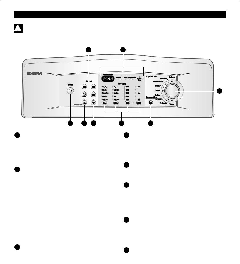
C G
B
A D E
A POWER (On/Off) BUTTON
Press to turn the dryer ON. Press again to turn the dryer OFF.
NOTE: Pressing the Power button during a cycle will cancel that cycle and any load settings
F H
D MY CYCLE BUTTON
Press the MY CYCLE button to select the memorized cycle. Cycle selections and settings are memorized by pressing and holding the button for 3 seconds.
(See page 23.)
B CYCLE SELECTOR KNOB-START/PAUSE
This knob is a dual function knob that is used both to select a cycle and to start or pause a cycle. Turn this knob to select the desired cycle. Once the desired cycle has been selected, the standard presets will be shown in the display. These settings can be adjusted using the Cycle Modifier or Option buttons anytime before starting the cycle. (See the cycle guide on page 19 for allowable settings. To protect your fabrics, not all settings are allowed in all cycles.)
Press this knob to START the selected cycle. If the dryer is running, use this knob to PAUSE the cycle without losing the current settings.
NOTE: If the dryer is stopped more than 4 minutes, the dryer will automatically turn off.
C OPTION BUTTONS
The option buttons allow you to select additional cycle options. Certain buttons also allow you to activate special functions by pressing and holding the button for 3 seconds.
MORE TIME and LESS TIME options are not available with sensor dry cycles.
For detailed information about the individual options, please see the following pages.
E RACK DRY BUTTON
selects preset temperature and time settings to rack dry items.
F CYCLE MODIFIER BUTTONS
Use these buttons to adjust the desired cycle options for the selected cycle. The lights above the buttons show the current selection. See page 22 for a complete discription (NOTE: Some settings are
not allowed on some cycles.).
G TIME AND STATUS DISPLAY
The display shows the estimated time remaining and the cycle status. The display also monitors the vent and lint screen status. See page 21 for a complete description.
H CANCEL/CYCLE BUTTON
The CANCEL/CYCLE button is used to stop the dryer and reset the controls.
17
HOW TO USE
OPERATING THE DRYER
1 SORT LAUNDRYAND LOAD DRYER |
|
Refer to page 20. |
5 SELECT CYCLE MODIFIERS |
|
|
|
Dry Level, Temp Control, Timed Dry and Cycle Signal |
|
Refer to page 22. |
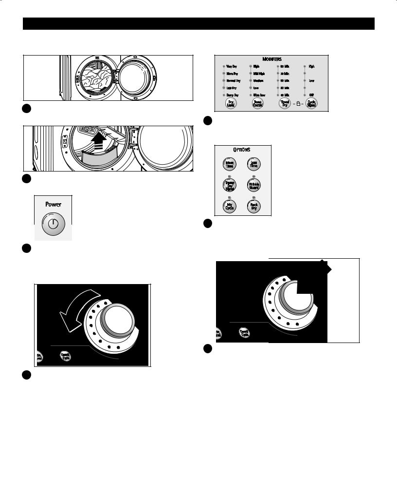
2 CHECK THE LINT FILTER
Refer to page 20.
3
4
6
TURN ON DRYER
Press the Power button to turn on the dryer. The lights around the Cycle Selector Knob will illuminate. Refer to page 17.
7
SELECT CYCLE
Turn the Cycle Selector Knob to the desired cycle. The display will show the preset Dry Level, Temperature, Time, and Option settings for that cycle. Manual Dry cycles also allow you to select a Timed Dry setting. Refer to page 17.
SELECT CYCLE OPTIONS
More Time, Less Time, Damp Dry Signal, Wrinkle Guard, My Cycle and Rack Dry Refer to page 23.
BEGIN CYCLE
Press the Cycle Selector Knob to begin the cycle. Pressing the Cycle Selector Knob after the dryer is running will Pause the dryer and retain the existing setting up to 4 minutes. Refer to page 17.
When the load is finished, the Cycle Signal (if set) will sound. If you have set the Wrinkle Guard option,
the dryer will tumble the load periodically for up to 3 hours. Refer to page 23 for Wrinkle Guard details.
Remove items from the dryer immediately after the end of the cycle to prevent further wrinkling.
Checking and cleaning the lint screen after every load is essential for dryer performance and preventing lint buildup and/or vent blockage.
18
 Loading...