

LG 47LB2RF Owner’s Manual

OWNER’S MANUAL
|
|
|
|
|
37LC2R* |
42PC1R* |
|
|
|
|
|
42LC2R* |
42PC3R* |
|
|
|
|
|
|
50PC1R* |
|
|
|
|
|
|
|
|
|
|
|
|
|
|
<![endif]>ITALIANO FRANÇAIS DEUTSCH ENGLISH
Please read Information Manual included together before reading this manual and operating your set.
Retain it for future reference.
Record model number and serial number of the set. See the label attached on the back cover and quote
this information to your dealer when you require service.
|
Model number |
: |
|
Serial number |
: |
|
|
|
P/NO: 38289U0025F (0605-REV00)
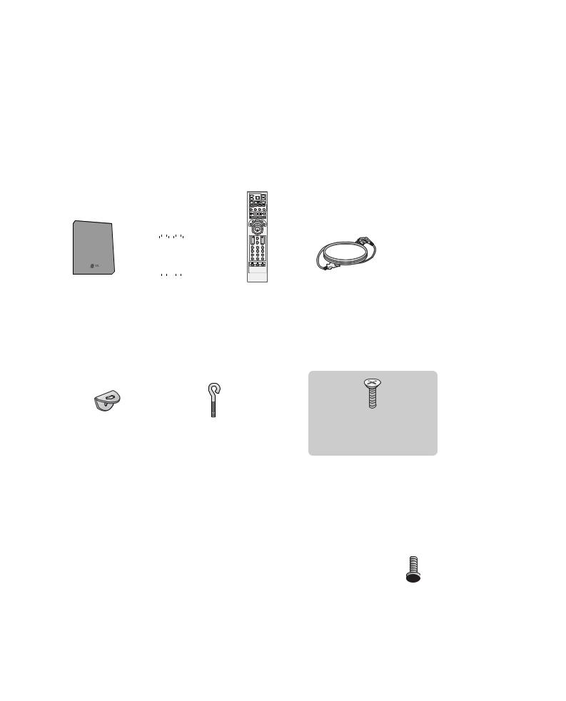
ACCESSORIES
Ensure that the following accessories are included with your TV. If an accessory is missing, please contact the dealer where you purchased the product.
<![endif]>ACCESSORIES
|
|
|
|
|
|
|
Power Cord |
Polishing Cloth |
|
|
|
|
|
|
|
||
|
|
|
|
|
|
|
||
|
|
|
|
|
|
|
||
|
|
|
|
|
|
|
||
|
|
|
|
|
|
|
||
|
|
|
|
|
|
|
||
|
|
|
|
|
|
|
Polish the screen with the cloth |
|
|
|
|
|
|
|
|
|
|
|
|
|
|
|
|
|
|
(Option) |
For 42PC1R*, 50PC1R*, 42PC3R*
2-bolts for stand assembly (Refer p.11)
This feature is not available for all models.
For 37LC2R*, 42LC2R*
2-TV brackets |
Twister Holder |
Cable |
2-bolts |
|
2-Wall brackets |
||||
Arrange the wires |
Management |
|
||
|
|
|||
|
with the twister holder. |
|
|
1

CONTENTS |
|
|
|
ACCESSORIES . . . . . . . . . . . . . . . . . . . . . . . . . . . . . . . . . . . . . . . . . . . . . |
. . . . . .1 |
|
INTRODUCTION |
|
| <![if ! IE]> <![endif]>CONTENTS |
Installing Batteries . . . . . . . . . . . . . . . . . . . . . . . . . . . . . . . . . . . . . . . . |
.9-10 |
|
Controls / Connection Options . . . . . . . . . . . . . . . . . . . . . . . . |
. .4-8 |
|
Remote Control Key Functions/ |
|
|
INSTALLATION |
|
Unfolding The Base Stand
Basic Connection /
How to Remove the Cable Management
How to join the product assembly to the wall
to protect the set tumbling . . . . . . . . . . . . . . . . . . . . . . . . . . . . . . . . . .14 Stand Installation . . . . . . . . . . . . . . . . . . . . . . . . . . . . . . . . . . . . . . . . . . . . . . . .15
CONNECTIONS & SETUP
Antenna Connection . . . . . . . . . . . . . . . . . . . . . . . . . . . . . . . . . . . . . . . . . . . .16
VCR Setup . . . . . . . . . . . . . . . . . . . . . . . . . . . . . . . . . . . . . . . . . . . . . . . . . . . . . .17-18
External Equipment Connections . . . . . . . . . . . . . . . . . . . . . . . .19
DVD Setup . . . . . . . . . . . . . . . . . . . . . . . . . . . . . . . . . . . . . . . . . . . . . . . . . . . .20-21
STB(SET-TOP BOX) Setup . . . . . . . . . . . . . . . . . . . . . . . . . . . . .22-23
PC Setup . . . . . . . . . . . . . . . . . . . . . . . . . . . . . . . . . . . . . . . . . . . . . . . . . . . . . .24-26
TURNING THE TV ON . . . . . . . . . . . . . . . . . . . . . . . . . . . . . . . . . . . . . . . . .27
SPECIAL FUNCTIONS
PIP (Picture-In-Picture) / Double Window / POP
Watching PIP/Double Window/POP . . . . . . . . . . . . . .28 Programme Selection for Sub Picture . . . . . . . . . . . .28 Input Source Selection for Sub Picture . . . . . . . . .29 Sub Picture Size Adjustment (PIP mode only)29 Moving the Sub Picture (PIP mode only) . . .29 Adjusting PIP Transparency (PIP mode only) 29 Swapping between main and sub pictures . . .30 POP
(Picture-out-of-Picture: Programme Scan) . . .30
Teletext
Teletext Language Selection(Option) . . . . . .31 Switch on/off . . . . . . . . . . . . . . . . . . . . . . . . .31 SIMPLE Text . . . . . . . . . . . . . . . . . . . . . . . . . .31 TOP Text . . . . . . . . . . . . . . . . . . . . . . . . . . . . .32 FASTEXT . . . . . . . . . . . . . . . . . . . . . . . . . . . . .32 Special Teletext Functions . . . . . . . . . . . . . . .33
TV MENU
On Screen Menus Selection and Adjustment . . . . .34
Setting up TV stations
Auto programme tuning . . . . . . . . . . . . . . . . . . . . . . . . . . . . . . .35 Manual programme tuning . . . . . . . . . . . . . . . . . . . . . . . . . . . .36 Fine tuning . . . . . . . . . . . . . . . . . . . . . . . . . . . . . . . . . . . . . . . . . . . . . . . . . .37 Assigning a station name . . . . . . . . . . . . . . . . . . . . . . . . . . . . . . .38 Booster (Option) . . . . . . . . . . . . . . . . . . . . . . . . . . . . . . . . . . . . . . . . .39 Programme edit . . . . . . . . . . . . . . . . . . . . . . . . . . . . . . . . . . . . . . . . . . .40 Favourite programme . . . . . . . . . . . . . . . . . . . . . . . . . . . . . . . . . . . .41
Calling the programme table . . . . . . . . . . . . . . . . . . . . . . . . .42
Picture Menu
PSM (Picture Status Memory) . . . . . . . . . . . . . . . . . . . . . .43 Picture Adjustment (PSM-User option) . . . . . . . . .44 CSM (Colour Status Memory) . . . . . . . . . . . . . . . . . . . . . .45 Manual Colour Temperature Control
(CSM - User option) . . . . . . . . . . . . . . . . . . . . . . . . . . . . . . . . . . . .46
Function . . . . . . . . . . . . . . . . . . . . . . . . . . . . . . . . . . . . . . . . . . .47
Advanced . . . . . . . . . . . . . . . . . . . . . . . . . . . . . . . . . . . . . . . . . . . . . . . . . . . .48
Reset . . . . . . . . . . . . . . . . . . . . . . . . . . . . . . . . . . . . . . . . . . . . . . . . . . . . . . . . . . .49
Sound Menu
SSM (Sound Status Memory) . . . . . . . . . . . . . . . . . . . . . . .50
Sound Frequency Adjustment
(SSM - User option) . . . . . . . . . . . . . . . . . . . . . . . . . . . . . . . . . . . .51 AVL (Auto Volume Leveler) . . . . . . . . . . . . . . . . . . . . . . . . . . .52 Balance Adjustment . . . . . . . . . . . . . . . . . . . . . . . . . . . . . . . . . . . . .52 Speaker . . . . . . . . . . . . . . . . . . . . . . . . . . . . . . . . . . . . . . . . . . . . . . . . . . . . . . .53 Stereo/Dual Reception . . . . . . . . . . . . . . . . . . . . . . . . . . . . . . . . .54 NICAM Reception . . . . . . . . . . . . . . . . . . . . . . . . . . . . . . . . . . . . . . . .55
Speaker Sound Output Selection . . . . . . . . . . . . . . . . . .55
Time Menu
Clock Setup . . . . . . . . . . . . . . . . . . . . . . . . . . . . . . . . . . . . . . . . . . . . . . . . .56
On/Off Time . . . . . . . . . . . . . . . . . . . . . . . . . . . . . . . . . . . . . . . . . . . . . . .57
Auto Sleep . . . . . . . . . . . . . . . . . . . . . . . . . . . . . . . . . . . . . . . . . . . . . . . . . .58
Sleep Timer . . . . . . . . . . . . . . . . . . . . . . . . . . . . . . . . . . . . . . . . . . . . . . . . .59
Special Menu
Child Lock . . . . . . . . . . . . . . . . . . . . . . . . . . . . . . . . . . . . . . . . . . . . . . . . . . .60
ISM (Image Sticking Minimization)
Method (Option) . . . . . . . . . . . . . . . . . . . . . . . . . . . . . . . . . . . . . . . . .61
Low Power (Option) . . . . . . . . . . . . . . . . . . . . . . . . . . . . . . . . . . . . .62
XD Demo . . . . . . . . . . . . . . . . . . . . . . . . . . . . . . . . . . . . . . . . . . . . . . . . . . . .62
2

TV MENU
Screen Menu
Auto Configure (RGB [PC] mode only) . . . . . . . . . . . .63
Manual Configure . . . . . . . . . . . . . . . . . . . . . . . . . . . . . . . . . . . . . . . .64
Setting the Picture Format . . . . . . . . . . . . . . . . . . . . . .65-66 Selecting Wide VGA/XGA mode . . . . . . . . . . . . . . . . . . .67 Initializing
(Reset to original factory settings)
APPENDIX
External Control Device Setup . . . . . . . . . . . . . . . . . . . . . .68-74
IR Codes . . . . . . . . . . . . . . . . . . . . . . . . . . . . . . . . . . . . . . . . . . . . . . . . . . . . . . .75 Remote control IR codes . . . . . . . . . . . . . . . . . . . . . . . . . . . . . . . . . .76 Programming the Remote . . . . . . . . . . . . . . . . . . . . . . . . . . . . . . . . .77 Programming code . . . . . . . . . . . . . . . . . . . . . . . . . . . . . . . . . . . . .78-79
Troubleshooting Checklist . . . . . . . . . . . . . . . . . . . . . . . . . . . .80-81
Maintenance . . . . . . . . . . . . . . . . . . . . . . . . . . . . . . . . . . . . . . . . . . . . . . . . . .82
Product Specifications . . . . . . . . . . . . . . . . . . . . . . . . . . . . . . . .83-84
<![endif]>CONTENTS
3
INTRODUCTION
CONTROLS
This is the front panel of models 42PC1R*, 50PC1R* TVs.
■ This is a simplified representation of a front panel. Here shown may be somewhat different from your TV.
Front Panel Controls
<![if ! IE]><![endif]>INTRODUCTION
Power/Standby Indicator
•illuminates red in standby mode.
•illuminates white when the set is switched on.
INPUT MENU OK
 VOL
VOL 
 PR
PR
|
|
|
|
|
|
|
|
|
|
|
|
|
|
|
|
|
|
|
|
|
|
|
|
|
INPUT Button |
|
|
|
|
|
|
|
|
|
|
|
|
|
|
|
|
|
|
|
|
|
|
|
|
|
OK Button |
|
|
PROGRAMME Buttons |
|||||
|
|
|
|
|
|
|
|
|
|
|
|
POWER Button |
|
|
|
|
|
|
|
|
|
||
|
|
MENU Button |
VOLUME Buttons |
||||||||
4

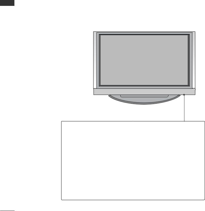
This is the front panel of models 42PC3R* TVs.
■ This is a simplified representation of a front panel. Here shown may be somewhat different from your TV.
<Front Panel >
Remote Control Sensor
Power/Standby Indicator
•illuminates red in standby mode.
•illuminates white when the set is switched on.
PR |
PROGRAMME Buttons |
VOLUME Buttons
VOL
OK 
 OK Button
MENU
MENU Button
INPUT
INPUT Button
POWER Button
<Side Panel >
<![endif]>INTRODUCTION
5
INTRODUCTION
<![endif]>INTRODUCTION
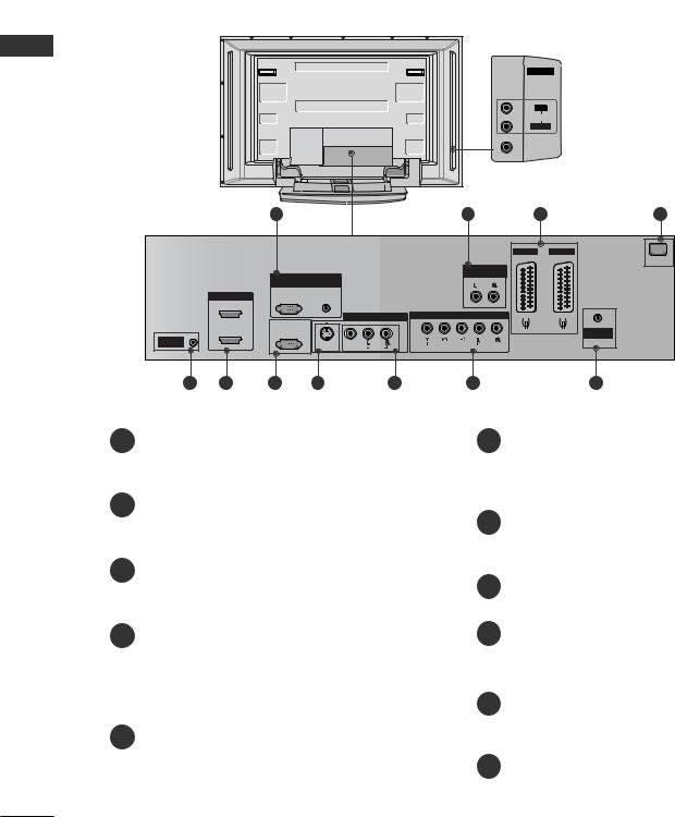
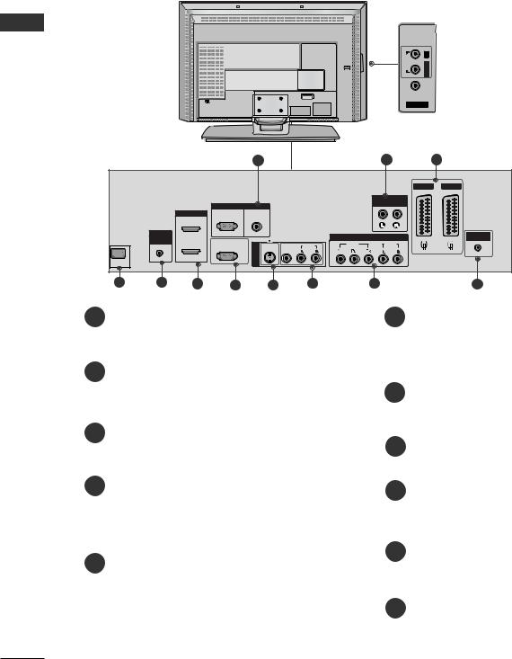
CONNECTION OPTION
This is the back panel of models 42PC1R*, 50PC1R*, 42PC3R* TVs.
Back Connection Panel
|
|
|
|
|
|
AV IN 4 |
AUDIO Input |
|
|
|
|
|
|
|
Connections are available for listening |
|
|
|
|
|
|
R |
stereo sound from an external device. |
|
|
|
|
|
|
AUDIO |
VIDEO Input |
|
|
|
|
|
|
L/MONO |
|
|
|
|
|
|
|
|
|
|
|
|
|
|
|
VIDEO |
Connects the video signal from a video |
|
|
|
|
|
|
|
|
|
|
|
|
|
|
|
device. |
|
|
|
|
|
|
(except 42PC3R*) |
|
|
|
1 |
|
|
2 |
3 |
4 |
|
|
|
|
|
|
AV 1 |
AV 2 |
|
|
|
|
|
|
|
AC IN |
|
|
|
|
|
|
ARIABLE |
|
|
|
RGB IN |
|
AUDIO OUT |
|
||
|
|
|
|
|
|
||
|
|
RGB |
AUDIO |
|
|
|
|
|
HDMI IN |
(PC/DTV) |
(RGB/DVI) |
|
|
|
|
|
2 |
|
|
|
|
|
|
|
|
|
|
AV IN 3 |
COMPONENT IN |
|
|
|
1 (DVI) |
-232C IN |
|
|
|
|
ANTENNA |
|
(CONTROL&SERVICE) |
|
|
|
|
||
REMOTE |
|
|
|
(MONO) |
|
|
IN |
|
|
|
|
|
|
||
CONTROLIN |
|
|
S-VIDEO |
VIDEO |
AUDIO |
|
|
|
|
|
|
||||
|
|
|
|
|
|
|
|
5 |
6 |
7 |
8 |
9 |
10 |
|
|
1
the appropriate input port.
2Variable Audio Output
Connect an external amplifier or add a subwoofer to your surround sound system.
3Euro Scart Socket (AV1/AV2)
Connect scart socket input or output from an external device to these jacks.
4Power Cord Socket
This TV operates on an AC power. The voltage is indicated on the Specifications page. Never attempt to operate the TV on DC power.
5 Remote Control Port
6HDMI Input
Connect a HDMI signal to HDMI IN.
Connect DVI(VIDEO) signal to HDMI/DVI port with DVI to HDMI cable.
7RS-232C Input(CONTROL&SERVICE)Port
Connect the serial port of the control devices to the RS-232C jack.
8S-Video Input
Connect S-Video out from an S-VIDEO device.
9Audio/Video Input
Connect audio/video output from an external device to these jacks.
10 Component Input
Connect a component video/audio device to these jacks.
11 Antenna Input
6
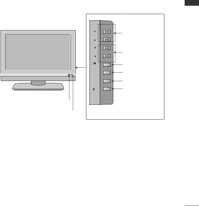
CONTROLS
This is the front panel of models 37LC2R*, 42LC2R* TVs.
■ This is a simplified representation of a front panel. Here shown may be somewhat different from your TV.
<Front Panel > |
|
PR |
PROGRAMME Buttons |
|
|
VOL |
VOLUME Buttons |
OK |
OK Button |
MENU |
MENU Button |
R |
|
INPUT |
INPUT Button |
/I |
POWER Button |
Remote Control Sensor |
|
<Side Panel > |
|
Power/Standby Indicator |
|
•illuminates red in standby mode.
•illuminates white when the set is switched on.
<![endif]>INTRODUCTION
7
INTRODUCTION
CONNECTION OPTION
This is the back panel of models 37LC2R*, 42LC2R* TVs.
Back Connection Panel
<![endif]>INTRODUCTION
|
|
|
|
|
|
|
<![if ! IE]> <![endif]>L/MONO R |
AUDIO Input |
|
|
|
|
|
|
<![if ! IE]> <![endif]>AUDIO |
Connections are available for listening |
|
|
|
|
|
|
|
stereo sound from an external device. |
||
|
|
|
|
|
|
<![if ! IE]> <![endif]>VIDEO |
|
VIDEO Input |
|
|
|
|
|
|
|
|
|
|
AC IN |
|
|
|
|
|
AV IN 4 |
Connects the video signal from a video |
|
|
|
|
|
|
|
|
|
|
|
|
|
|
|
|
|
device. |
|
|
1 |
|
|
|
|
|
3 |
|
|
|
|
|
|
|
AV 1 |
AV 2 |
|
|
|
|
|
|
VARIABLE |
|
|
|
RGB IN |
|
|
|
|
AUDIO OUT |
|
|
|
|
|
|
|
|
|
|
|
HDMI |
RGB |
AUDIO |
|
|
|
|
|
|
|
(PC/DTV) |
(RGB/DVI) |
|
|
|
|
|
|
REMOTE |
|
|
|
|
COMPONENT IN |
|
ANTENNA |
|
COMTROL |
|
|
|
|
|
IN |
||
IN |
RS-232C IN |
|
|
|
|
|
|
|
| <![if ! IE]> <![endif]>3 |
S-VIDEO VIDEO |
AUDIO |
VIDEO |
AUDIO |
|
|
||
|
(CONTROL&SERVICE) |
|
|
|
|
|||
|
|
<![if ! IE]> <![endif]>IN |
|
(MONO) |
|
|
|
|
AC IN |
|
|
|
|
|
|
|
|
4 |
5 |
8 |
10 |
11 |
|
|
1
to the appropriate input port.
2Variable Audio Output
Connect an external amplifier or add a subwoofer to your surround sound system.
3Euro Scart Socket (AV1/AV2)
Connect scart socket input or output from an external device to these jacks.
4Power Cord Socket
This TV operates on an AC power. The voltage is indicated on the Specifications page. Never attempt to operate the TV on DC power.
5 Remote Control Port
6
Connect a HDMI signal to HDMI IN. Connect DVI(VIDEO) signal to HDMI/DVI port with DVI to HDMI cable.
7RS-232C Input(CONTROL&SERVICE)Port
Connect the serial port of the control devices to the RS-232C jack.
8S-Video Input
Connect S-Video out from an S-VIDEO device.
9Audio/Video Input
Connect audio/video output from an external device to these jacks.
10 Component Input
Connect a component video/audio device to these jacks.
11 Antenna Input
8
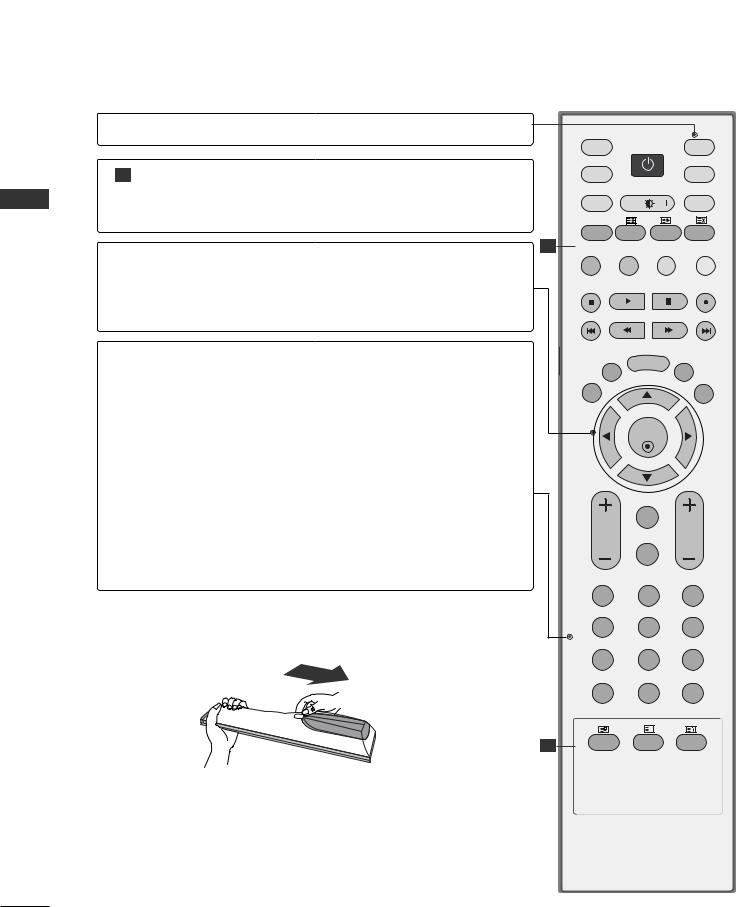
REMOTE CONTROL KEY FUNCTIONS
POWER Switches the set on from standby or off to standby.
TV INPUT Returns from AV1, AV2, S-Video2, AV3, AV4(except 42PC3R*), Component, RGB, HDMI1/DVI or
HDMI 2 to the TV mode. Switches the set on from standby.
INPUT If you press the button once, the input source OSD will appear on screen as shown. Press the D / E button and then OK button to select the desired input source (TV, AV1,
AV2, S-Video2, AV3, AV4(except 42PC3R*), Component, RGB, HDMI1/DVI or HDMI 2).
ARC Selects your desired picture format.
Brightness
adjustment Adjusts screen brightness.
It returns to the default settings brightness by changing mode source.
PIP Switches the sub picture PIP, DW, POP or off mode.
SIZE Adjusts the sub picture size.
POSITION Moves the sub picture.
PIP PR - /+ Selects a programme for the sub picture.
SWAP Exchanges the main/sub images in PIP/Double window/POP mode.
PIP INPUT Selects the input source for the sub picture in PIP/Doubel window mode.
Coloured These buttons are used for teletext (only TELETEXT buttons models) or Programme edit.
VCR/DVD Controls some video cassette recorders or DVD players control buttons when you have already selected DVD or VCR mode button.
EXIT Clears all on-screen displays and returns to TV viewing from any menu.
LIST Displays the programme table.
MENU Selects a menu.
I/II Selects the sound output.
SLEEP Sets the sleep timer.
INPUT |
|
|
|
TV |
POWER |
TV |
|
INPUT |
|
|
DVD |
ARC |
|
|
VCR |
TEXT |
PIP |
SIZE |
POSTION |
PIP PR- |
PIP PR+ |
SWAP |
PIP INPUT |
LIST |
MENU |
I/II |
|
|
|
EXIT |
|
SLEEP |
OK
|
Q.VIEW |
VOL |
PR |
|
MUTE |
1 |
2 |
3 |
4 |
5 |
6 |
7 |
8 |
9 |
* |
0 |
FAV |
|
|
|
|
? |
|
TIME |
REVEAL |
INDEX |
<![endif]>INTRODUCTION
9
INTRODUCTION
REMOTE CONTROL KEY FUNCTIONS
MODE Selects the remote operating modes.
1 TELETEXT These buttons are used for teletext. BUTTONS For further details, see the ‘Teletext’ section.
<![endif]>INTRODUCTION
THUMBSTICK
(Up/Down/Left
Right)
OK
VOLUME UP /DOWN
Q.VIEW
MUTE
Programme
UP/DOWN
0~9 number button
FAV
*
1
Allows you to navigate the on-screen menus and adjust the system settings to your preference.
Accepts your selection or displays the current mode.
Adjusts the volume.
Returns to the previously viewed programme.
Switches the sound on or off.
Selects available programmes.
Selects a programme.
Selects numbered items in a menu.
Displays the selected favourite programme.
No function
INSTALLING BATTERIES
1
•Open the battery compartment cover on the back side and insert the batteries with correct polarity.
•Install two 1.5V alkaline batteries of AA type. Don’t mix used batteries with new batteries.
TV |
POWER |
TV |
|
INPUT |
|
|
DVD |
ARC |
|
|
VCR |
TEXT |
PIP |
SIZE |
POSTION |
PIP PR- |
PIP PR+ |
SWAP |
PIP INPUT |
LIST |
MENU |
I/II |
|
|
|
EXIT |
|
SLEEP |
OK
Q.VIEW
VOL
MUTE
1 |
2 |
3 |
4 |
5 |
6 |
7 |
8 |
9 |
* |
0 |
FAV |
|
|
|
|
? |
|
TIME |
REVEAL |
INDEX |
10
INSTALLATION
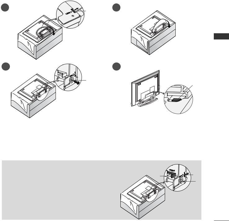
UNFOLDING THE BASE STAND (42PC1R*, 42PC3R*)
■ This feature is not available for all models.
1 |
2 |
3
B
C
<![endif]>INSTALLATION
the set with the screen facing down on a cushion or soft cloth as shown in Figure 1. unfolding the stand, please make sure two locks (A) on the bottom of the stand push
the stand out as shown above in Figures 2 ~ 3.
unfolding the stand, please insert |
tighten the screws in the holes (B) on the bottom of the stand. |
connecting cables to the set, do |
disengage the lock (C). |
may cause the set to fall, causing serious bodily injury and serious damage to the set.
 NOTE
NOTE
shown here may be slightly different from your set. |
D |
A |
|
||
en closing the stand for storage |
|
B |
|
|
First remove the screws in the holes (B) on the bottom
of the stand. And then pull two Hooks (D) of the stand bottom
and fold the stand into the back of the set.
After folding, push two Locks (A) of the stand bottom outward.
11
INSTALLATION
<![endif]>INSTALLATION
BASIC CONNECTION (42PC1R*, 42PC3R*, 50PC1R*)
■ These models have two cable arrangement methods according to the stand type.
Stand type 1
Arrange the cables as shown picture.
Stand type 2
1 Hold
hands
CABLE MANAGEMENT
2 Connect the cables as necessary.
To connect an additional equipment, see the External equipment Connections section.
3 Reinstall the CABLE MANAGEMENT as
shown.
12
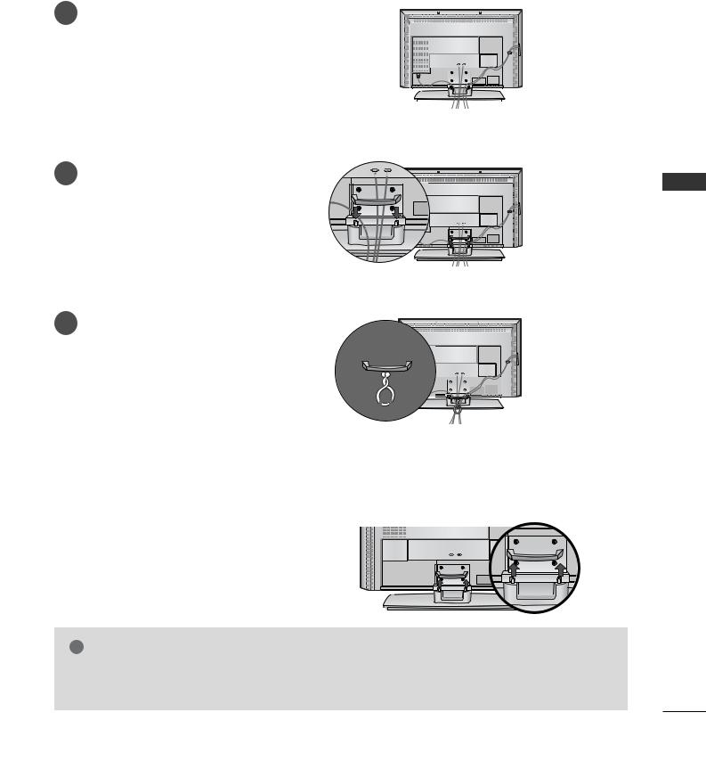
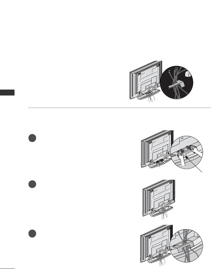
BASIC CONNECTION (37LC2R*, 42LC2R*)
1 |
the cables as necessary. |
|
|
|
|
|
|
|
|
|
|
|
|
|
|
|
|
|
|
|
|
|
|
|
|
|
|
|
|
|
connecting the cables neatly, arrange |
|
|
|
|
|
|
|
|
|
|
|
|
|
|
|
|
|
|
|
|
|
|
|
|
|
|
|
|
|
the cables to the Cable Holder. |
|
|
|
|
|
|
|
|
|
|
|
||
|
|
|
|
|
|
|
|
|
|
|
|
|
|
|
|
To connect an additional equipment, see the |
|
|
|
|
|
|
|
|
|
|
|
|
|
|
|
|
|
|
|
|
|
|
|
|
|
|||
|
External equipment Connections sec- |
|
|
|
|
|
|
|
|
|
|
|
||
|
tion. |
|
|
|
|
|
|
|
|
|
|
|
|
|
|
|
|
|
|
|
|
|
|
|
|
|
|
|
|
|
|
|
|
|
|
|
|
|
|
|
|
|
|
|
|
|
|
|
|
|
|
|
|
|
|
|
|
|
|
2
3
CABLE MANAGEMENT
<![if ! IE]><![endif]>INSTALLATION
cables using the supplied
HOW TO REMOVE THE CABLE
Hold hands
! NOTE
G Do not hold the CABLE MANAGEMENT when moving the product.
If the product is dropped, you may be injured or the product may be broken.
13
INSTALLATION
<![endif]>INSTALLATION
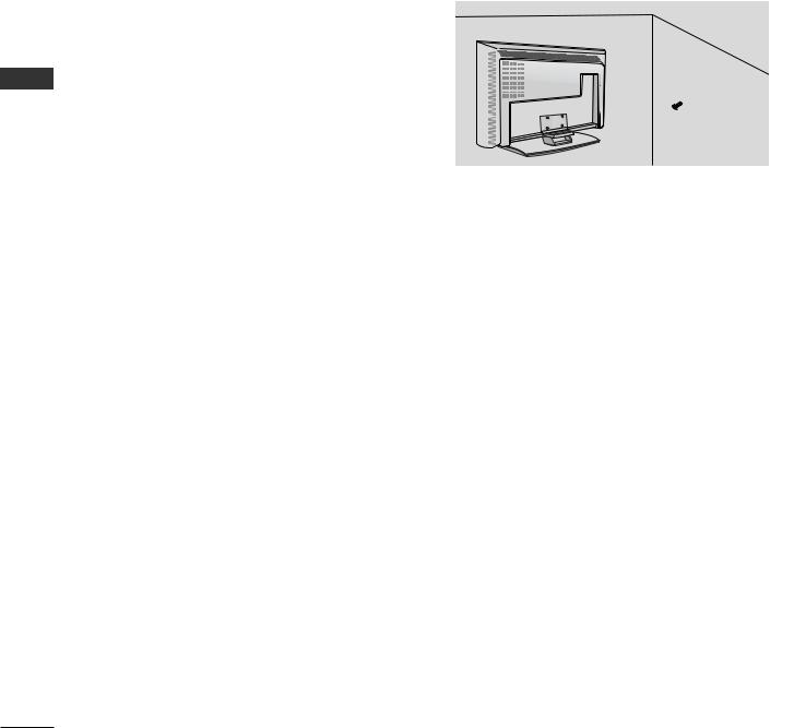
HOW TO JOIN THE PRODUCT ASSEMBLY TO THE WALL TO PROTECT THE SET TUMBLING
■Set it up close to the wall so the product doesn’t fall over when it is pushed backwards.
■The instructions shown below is a safer way to set up the product, which is to fix it on the wall so the product doesn’t fall over when it is pulled in the forward direction. It will prevent the product from falling forward and hurting people. It will also prevent the product from damage caused by fall. Please make sure that children don’t climb on or hang from the product.
1 |
2 |
|
1 |
or |
2 |
1 bolts or TV brackets/bolts to fix the product to the wall as shown in the picture.
(If your product has the bolts in the eye-bolts position before inserting the eye-bolts, loosen the bolts.) * Insert the eye-bolts or TV brackets/bolts and tighten them securely in the upper holes.
2Secure the wall brackets with the bolts (not provided as parts of the product, must purchase separately) on the wall. Match the height of the bracket that is mounted on the wall.
3 |
Use a sturdy rope (not provided as parts of the product, must purchase separately) to tie the product. It is safer to tie the rope so it becomes horizontal between the wall and the product.
! NOTE
GWhen moving the product to another place undo the ropes first.
GUse a product holder or a cabinet that is big and strong enough for the size and weight of the product.
GTo use the product safely make sure that the height of the bracket that is mounted on the wall is same as that of the product.
14
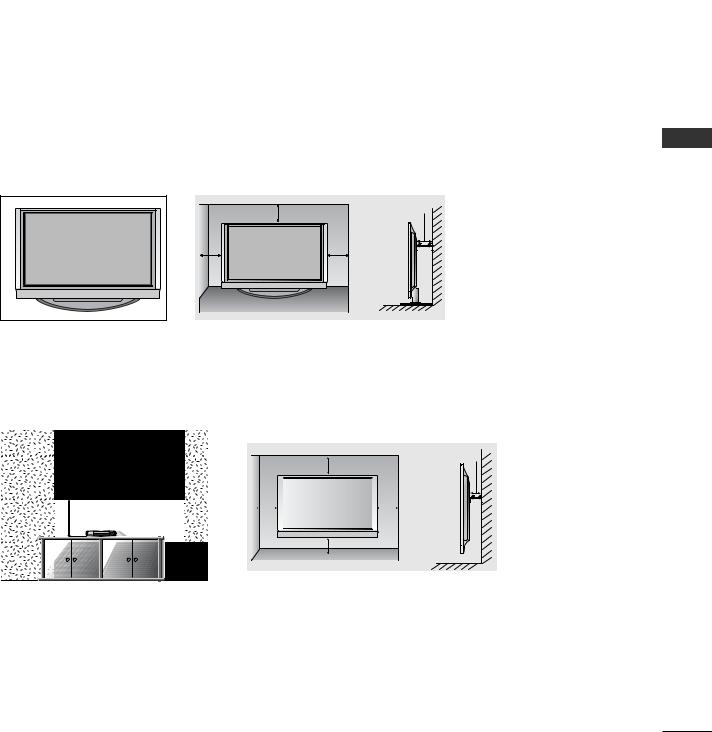
STAND INSTALLATION
■The TV can be installed in various ways such as on a wall, or on a desktop etc.
■The TV is designed to be mounted horizontally.
GROUNDING
Ensure that you connect the earth ground wire to prevent possible electric shock. If grounding methods are not possible, have a qualified electrician install a separate circuit breaker. Do not try to ground the unit by connecting it to telephone wires, lightening rods, or gas pipes.
Power
Supply
Short-circuit
Breaker
Desktop Pedestal Installation
For proper ventilation, allow a clearance of 4” on each side and from the wall.
|
4 inches |
4 inches |
|
|
|
4 inches |
|
4 inches |
Wall Mount: Horizontal installation
For proper ventilation, allow a clearance of 4" on each side and from the wall. Detailed installation instructions are available from your dealer, see the optional Tilt Wall Mounting Bracket Installation and Setup Guide.
4 inches
4 inches
|
|
4 inches |
|
|
4 inches |
|
|
|
|
|
|||
|
|
|
|
|
|
|
|
|
|
|
|
|
|
|
|
|
|
|
|
|
|
|
|
|
|
|
|
|
|
|
|
|
|
|
4 inches
<Only 42PC1R*, 42PC3R*>
Remove two screws of the backside of the set before installing the wall mounting bracket.
<![endif]>INSTALLATION
15
CONNECTIONS & SETUP
<![endif]>SETUP & CONNECTIONS
■ To prevent the equipment damage, never plug in any power cords until you have finished connecting all equipment.
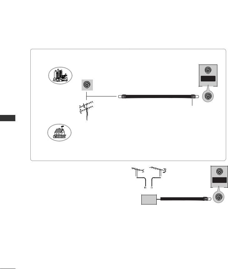
ANTENNA CONNECTION
■For optimum picture quality, adjust antenna direction.
■An antenna cable and converter are not supplied.
Multi-family Dwellings/Apartments (Connect to wall antenna socket)
VHF Antenna
UHF Antenna
Wall Antenna Socket
NTENNA |
IN |
ANTENNA
IN
RF Coaxial Wire (75 ohm)
Turn clockwise to tighten.
Outdoor Antenna
Single-family Dwellings /Houses
(Connect to wall jack for outdoor antenna)
■ In poor signal areas, to get better picture quality, |
|
|
|
install a signal amplifier to the antenna as shown |
VHF |
UHF |
ANTENNA |
to the right. |
|
|
IN |
|
|
|
■ If signal needs to be split for two TVs, use an 
 antenna signal splitter for connection. Signal
Amplifier
16
VCR SETUP
■To avoid picture noise (interference), leave an adequate distance between the VCR and TV.
■Typically a frozen still picture from a VCR. If the 4:3 picture format is used; the fixed images on the sides of the screen may remain visible on the screen.
When connecting with an antenna
1 |
|
|
|
VCR |
|
|
|
|
IN |
|
|
|
S-VIDEO |
|
|
|
|
|
OUT |
|
|
AV 1 AV 2 |
OUTPUT |
|
2 |
Connect the antenna cable to the ANT IN |
SWITCH (R) AUDIO (L) VIDEO |
||
|
3 |
4 |
||
|
|
|
AC IN |
|
|
antenna socket of the VCR. |
|
|
|
3 |
Press the PLAY button on the VCR and match |
|
IN |
|
|
|
|
ANTENNA |
|
|
the appropriate programme between the TV and |
|
|
|
|
VCR for viewing. |
|
|
|
When connecting with a RCA cable
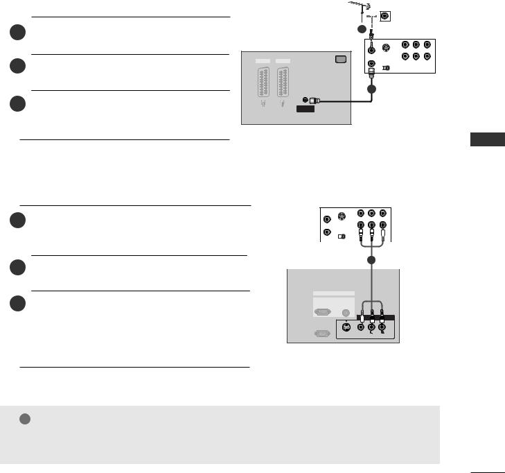
1 DIO/VIDEO jacks between TV and jack colors (Video = yellow, Audio Left =
white, and Audio Right = red)
2Insert a video tape into the VCR and press PLAY on the VCR. (Refer to the VCR owner’s manual.)
3Select AV3 input source using the INPUT button on the remote control.
- If connected to AV IN4, select AV4 input source. (except 42PC3R*)
VCR |
ANT IN |
|
IN |
|
|
S-VIDEO |
|
|
|
|
ANT OUT |
|
OUT |
|
|
OUTPUT |
|
|
|
|
SWITCH |
(R) |
VIDEO |
|
|
3 |
4 |
|
|
|
|
|
|
|
|
|
|
|
|
|
|
|
|
|
|
|
|
|
|
|
|
1 |
|
||||||
|
|
|
|
|
|
|
|
||
|
|
RGB IN |
|||||||
|
RGB |
|
AUDIO |
||||||
(PC/DTV) |
|
(RGB/DVI) |
|||||||
3
RS-232C IN
(CONTROL&SERVICE)
)
S-VIDEO VIDEO
! NOTE
G If you have a mono VCR, connect the audio cable from the VCR to the AUDIO L/M O jack of the set.
<![endif]>SETUP & CONNECTIONS
17
CONNECTIONS & SETUP
VCR SETUP
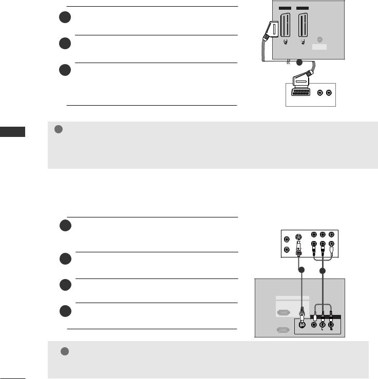
When connecting with a Euro Scart
TV Back
1 |
Euro scart socket of the VCR to the AV1 |
|
|
on the set. |
|
|
|
|
2Insert a video tape into the VCR and press PLAY on the VCR. (Refer to the VCR owner’s manual.)
AV 1 |
AV 2 |
|||||
|
|
|
|
|
|
|
|
|
|
|
|
|
|
|
|
|
|
|
|
|
|
|
|
|
|
|
|
|
|
|
|
|
|
|
|
|
|
|
|
|
|
|
|
|
|
|
|
|
|
|
|
|
|
|
|
|
|
|
|
|
|
|
|
|
|
|
|
|
|
|
|
|
|
|
|
|
|
|
|
|
|
|
|
|
|
|
|
|
|
|
|
|
|
|
|
|
|
|
|
|
|
|
|
|
|
|
|
|
|
|
|
|
|
|
|
|
|
|
|
|
|
|
|
|
|
|
|
|
|
|
|
|
|
|
|
|
|
|
|
ANTENNA
IN
1
<![endif]>SETUP & CONNECTIONS
3 Select AV1 input source with using the INPUT button on
the remote control. |
|
- If connected to AV2 |
Euro scart socket, select AV2 |
input source. |
(R) AUDIO (L) VCR |
! NOTE
GIf the S-VIDEO(Y/C) signal is received through the Euro scart socket 2 (AV2), you must change to the S-Video2 mode.
GIf you want to use the EURO scart cable, you have to use the signal shielded Euro scart cable.
When connecting with an S-Video cable
1 output of the VCR to the set. The picture quality is
improved; compared to normal composite (RCA cable) input.
2Connect the audio outputs of the VCR to the AUDIO input jacks on the set.
3Insert a video tape into the VCR and press PLAY on the VCR. (Refer to the VCR owner’s manual.)
Select AV3 input source with using the INPUT button on the remote control.
ANT IN |
IN |
VCR |
|
S- |
|
ANT OUT |
OUT |
|
|
3 |
(R) AUDIO (L) VIDEO |
|
|
12
RGB IN |
|
|
RGB |
AUDIO |
|
(PC/DTV) |
(RGB/DVI) |
|
|
|
AV IN 3 |
RS-232C IN |
|
|
(CONTROL&SERVICE) |
|
|
|
S-VIDEO VIDEO |
(MONO) |
|
AUDIO |
|
! NOTE
GIf both S-Video and VIDEO sockets have been connected to the S-VHS VCR simultaneousiy. only the S-Video can be received.
18
EXTERNAL EQUIPMENT CONNECTIONS
1 between TV and colors (Video = yel
low, Audio Left = white, and Audio Right = red).
2 Select AV4 input source with using the INPUT button on the remote control(except 42PC3R*).
3 Operate the corresponding external equipment. Refer to |
Camcorder |
|
|
|
|
|
|
||||
|
|
|
|
||
|
external equipment operating guide. |
|
|
|
|
|
|
Video Game Set |
|
|
|
|
|
|
|
||
|
|
|
|
||
AV IN 4
R
AUDIO
L/MONO
VIDEO
1
R AUDIO L |
VIDEO |
<![endif]>SETUP & CONNECTIONS
19
CONNECTIONS & SETUP
<![endif]>SETUP & CONNECTIONS
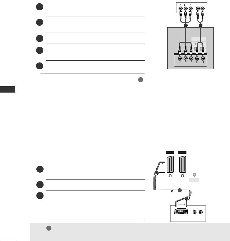
DVD SETUP
When connecting with a component cable
|
DVD |
|
1 |
B |
R (R) AUDIO (L) |
|
|
2Connect the audio outputs of the DVD to the COMPONENT IN AUDIO jacks on the set.
3 Turn on the DVD player, insert a DVD.
4Select Component input source with using the INPUT button on the remote control.
5 Refer to the DVD player's manual for operating instructions.
12
VARIABLE
AUDIO OUT
COMPONENT IN
 VIDEO
VIDEO
 AUDIO
AUDIO
|
|
|
|
! NOTE |
|
|
|
|
|
|
|
|
|
|
|||||||
|
|
|
G Component Input p |
ts |
|
|
|
||||||||||||||
|
|
|
|
To get better picture quality, connect a DVD |
|||||||||||||||||
|
|
|
|
player to the |
|
|
|
|
input ports as |
||||||||||||
|
|
|
|
shown below. |
|
|
|
|
|
|
|
|
|
|
|||||||
|
|
|
|
|
|
|
|
|
|
|
|
|
|
||||||||
|
|
|
|
Component ports on the TV |
|
|
Y |
|
PB |
|
PR |
|
|
||||||||
|
|
|
|
|
|
|
|
|
|
|
|
|
|
|
|
|
|
|
|
||
|
|
|
|
|
|
|
|
|
|
|
|
|
|
Y |
|
Pb |
|
Pr |
|
|
|
|
|
|
|
|
Video output ports |
|
|
Y |
|
B-Y |
R-Y |
|
|||||||||
|
|
|
|
|
on DVD player |
|
|
Y |
|
Cb |
|
Cr |
|
||||||||
|
|
|
|
|
|
|
|
|
|
|
|
|
|
Y |
PB |
PR |
|
||||
|
|
|
|
|
|
|
|
|
|
|
|
|
|
|
|
|
|
|
|
|
|
When connecting with a Euro Scart |
|
|
|
|
|
|
|
|
|
|
|||||||||||
|
|
|
|
|
|
|
|
|
|
|
|
|
|
|
|
|
|
|
|
|
|
|
|
|
|
|
|
|
|
AV 1 |
|
AV |
|
|
|
|
|
|
|||||
|
|
|
|
|
|
|
|
|
|
|
|
|
|
|
|
|
|
|
|
|
|
|
|
|
|
|
|
|
|
|
|
|
|
|
|
|
|
|
|
|
|
|
|
|
|
|
|
|
|
|
|
|
|
|
|
|
|
|
|
|
|
|
|
|
|
|
|
|
|
|
|
|
|
|
|
|
|
|
|
|
|
|
|
|
|
|
|
1 |
Euro scart socket of the DVD to the AV1 |
|
|
|
|
|
|
|
|
|
|
|
|
|
|
|
|
||||
|
|
|
|
|
|
|
|
|
|
|
|
|
|
|
|
||||||
|
|
|
|
|
|
|
|
|
|
|
|
|
|
|
|
||||||
|
|
|
|
|
|
|
|
|
|
|
|
|
|
|
|
||||||
|
|
on the set. |
|
|
|
|
|
|
|
|
|
|
|
|
|
|
|
|
|||
|
|
|
|
|
|
|
|
|
|
|
|
|
|
|
|
|
ANTENNA |
|
|
|
|
|
|
|
|
|
|
|
|
|
|
|
|
|
|
|
|
|
|
|
|
||
|
|
|
|
|
|
|
|
|
|
|
|
|
|
|
|
|
IN |
|
|
|
|
2 Turn on the DVD player, insert a DVD. |
|
|
|
|
|
|
|
|
|
|
|
|
|
|
|
|
|||||
|
|
|
|
|
|
|
|
|
|
|
|
1 |
|
|
|
|
|
|
|
|
|
3Select AV1 input source with using the INPUT button on the remote control.
-If connected to AV2 Euro scart socket, select AV2 input source.
DVD
(R) AUDIO (L)
VIDEO
! NOTE
G Please use the shield scart cable.
20
When connecting with a S-Video cable
1
2Connect the audio outputs of the DVD to the AUDIO input jacks on the set.
3 Turn on the DVD player, insert a DVD.
4Select AV3 input source with using the INPUT button on the remote control.
5 Refer to the DVD player's manual for operating instructions.
DVD
(R) AUDIO (L) S-VIDEO
2
RGB IN
RGB |
AUDIO |
(PC/DTV) |
(RGB/DVI) |
|
|
AV IN 3 |
RS-232C IN |
|
|
(CONTROL&SERVICE) |
|
|
S |
|
(MONO) |
VIDEO |
AUDIO |
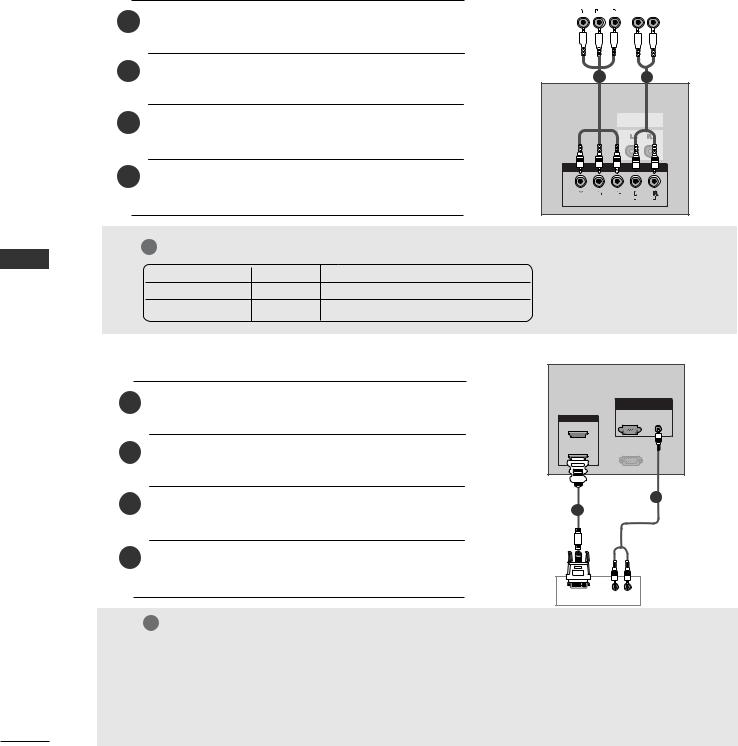
When connecting with a HDMI cable
1
2Select HDMI1/DVI or HDMI2 input source with using the INPUT button on the remote control.
3 Refer to the DVD player's manual for operating instructions.
HDMI IN
2
1 (DVI)
REMOTE
CONTROLIN
HDMI IN
2
1
DVD
HDMI OUTPUT
! NOTE
GTV can receive the video and audio signal simultaneously with using a HDMI cable.
GIf the DVD supports Auto HDMI function, the DVD output resolution will be automatically set to 1280x720p.
GIf the DVD does not support Auto HDMI, you need to set the output resolution appropriately. To get the best picture quality, adjust the output resolution of the DVD to 1280x720p.
<![endif]>SETUP & CONNECTIONS
21
CONNECTIONS & SETUP
STB(SET-TOP BOX) SETUP
■This TV can receive Digital Over-the-air/Cable signals without an external digital set-top box. However, if you do receive Digital signals from a digital set-top box or other digital external device, refer to the figure as shown below.
When connecting with a component cable
Digital Set-top Box
1 PB, PR) of the digital
T IN VIDEO jacks on the set.
|
|
|
B |
R |
(R) AUDIO (L) |
||||||
|
|
|
|
|
|
|
|
|
|
|
|
|
|
|
|
|
|
|
|
|
|
|
|
|
|
|
|
|
|
|
|
|
|
|
|
2Connect the audio output of the digital set-top box to the COMPONENT IN AUDIO jacks on the set.
3Turn on the digital set-top box. (Refer to the owner’s manual for the digital set-top box.)
4Select Component input source with using the INPUT button on the remote control.
2
VARIABLE
COMPONENT 
 VIDEO
VIDEO
<![endif]>SETUP & CONNECTIONS
! NOTE
Signal |
Component |
RGB-DTV |
HDMI1/DVI (DTV) |
HDMI2 (DTV) |
480i/576i |
Yes |
No |
No |
No |
480p/576p/720p/1080i |
Yes |
Yes |
Yes |
Yes |
|
|
|
|
|
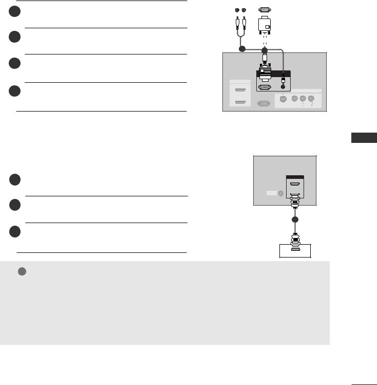
When connecting with a HDMI to DVI cable
1 |
set-top box to the |
AV IN 3
2 Connect the audio outputs of RSthe-232C IN set-top box to the AUDIO(RGB/DVI) jack on the set.S-VIDEO VIDEO (AUDIO)
3Turn on the digital set-top box. (Refer to the owner’s manual for the digital set-top box.)
4Select HDMI1/DVI input source with using the INPUT button on the remote control.
! NOTE
RGB
(PC/DTV) (RGB/DVI)
RS-232C (CONTROL&
2
1
|
Digital Set-top |
DVI |
(R) AUDIO (L) Box |
GIf the digital set-top box has a DVI output and no HDMI output, a separated audio connection is necessary.
G If the digital set-top box supports HDMIAutoIN DVI function, the output resolution of the digital
2
set-top box will be automatically set to 1280x720p.
G If the digital set-top box does not support1 (DVI) Auto DVI, you need to set the output resolution appropriately. To get the best picture quality, adjust the output resolution of the digital set-top box to 1280x720p.
22
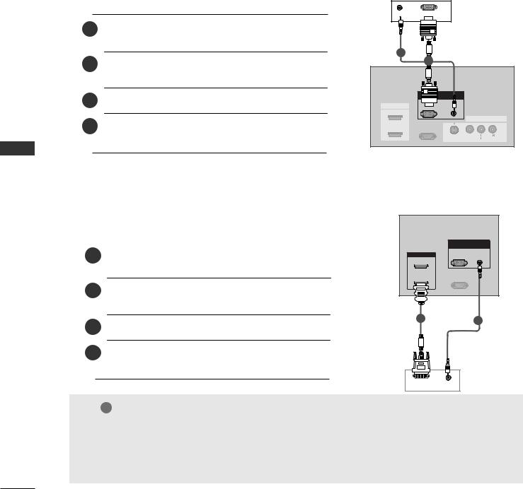
When connecting with a D-sub 15 pin cable
1 |
the digital set-top box to |
|
on the set. |
2Connect the audio outputs of the set-top box to the AUDIO (RGB/DVI) jack on the set.
3Turn on the digital set-top box. (Refer to the owner’s manual for the digital set-top box.)
4Select RGB-DTV input source with using the INPUT button on the remote control.
Digital Set-top Box
(R) AUDIO (L) |
RGB-DTV OUTPUT |
||||||||||
|
|
|
|
|
|
|
|
|
|
|
|
|
|
|
|
|
|
|
|
|
|
|
|
|
|
|
|
|
|
|
|
|
|
|
|
|
|
|
|
|
|
|
|
|
|
|
|
|
|
|
|
|
|
|
|
|
|
|
|
|
|
|
|
|
|
|
|
|
|
|
|
|
|
|
|
|
|
|
|
|
|
|
|
|
|
|
|
|
|
|
|
|
|
|
|
|
|
|
|
|
|
|
|
|
|
|
|
2 |
|
|
|
|
|
|
RGB IN |
|
|
HDMI IN |
(PC/DTV) |
AUDIO |
|
|
(RGB/DVI) |
|
|||
2 |
|
|
|
|
|
|
|
|
AV IN 3 |
|
RS |
IN |
|
|
1 (DVI) |
|
VICE) |
|
|
|
|
|
S-VIDEO |
(MONO) |
|
|
|
AUDIO |
|
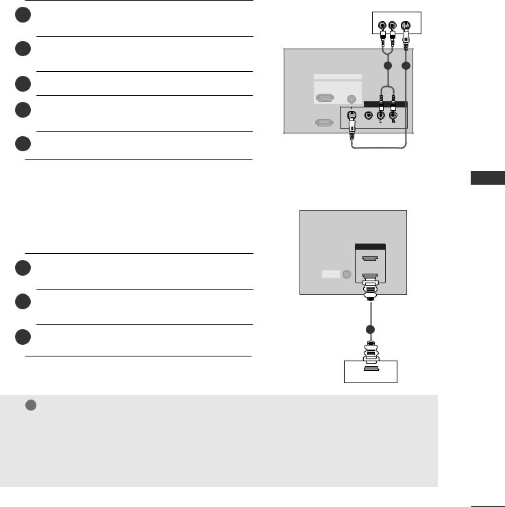
When connecting with a HDMI cable
|
|
ANTENNA |
|
|
IN |
|
|
|
1 |
digital set-top box to |
|
2Select HDMI1/DVI or HDMI2 input source with using the INPUT button on the remote control.
3Turn on the digital set-top box. (Refer to the owner’s manual for the digital set-top box.)
|
|
RGB IN |
|
|
RGB |
HDMI IN |
(PC/DTV) |
|
2 |
|
|
1 (DVI) |
REMOTE |
-232C IN |
CONTROLIN |
&SERVICE) |
|
1
Digital Set-top |
x |
HDMI OUTPUT
! NOTE
GTV can receive the video and audio signal simultaneously with using a HDMI cable.
GIf the digital set-top box supports Auto HDMI function, output resolution of the digital set-top box will be automatically set to 1280x720p.
GIf the digital set-top box does not support Auto HDMI, you need to set the output resolution appropriately. To get the best picture quality, adjust the output resolution of the digital set-top box to 1280x720p.
<![endif]>SETUP & CONNECTIONS
23
CONNECTIONS & SETUP
<![endif]>SETUP & CONNECTIONS
PC SETUP
■ This TV provides Plug and Play capability, meaning that the PC adjusts automatically to the TV's settings.
When connecting with a D-sub 15 pin cable
1 |
the PC to the RGB IN |
2Connect the audio outputs of the PC to the AUDIO (RGB/DVI) jack on the set.
|
RGB IN |
3 |
RGB |
(PC/DTV) |
|
Turn on the PC and the set. |
|
4 |
AV IN 3 |
Select RGB-PC input source with using the INPUT |
S-232C IN
ROL&SERVICE)
button on the remote control.
AUDIO RGB |
PC |
2 |
|
|
|
|
|
1 |
|
|
|
|
RGB IN |
|
|
|
HDMI IN |
(PC/DTV) |
AUDIO |
|
|
(RGB/DVI) |
|
|
||
2 |
|
|
|
|
|
|
|
|
AV IN 3 |
|
RS-232C IN |
|
|
|
1 (DVI) |
(CONTROL&SERVICE) |
|
|
|
|
|
S-VIDEO |
|
(MONO) |
|
|
VIDEO |
AUDIO |
|
When connecting with a HDMI to DVI cable
|
|
RGB IN |
|
|
RGB |
|
|
(PC/DTV) |
|
|
|
1 |
the |
|
2Connect the audio outputs of the PC to the AUDIO (RGB/DVI) jack on the set.
3 Turn on the PC and the set.
4Select HDMI1/DVI input source with using the INPUT button on the remote control.
|
RGB IN |
|
|
RGB |
AUDIO |
HDMI IN |
(PC/DTV) |
(RGB/DVI) |
2 |
|
|
1 (DVI) |
RS-232C IN |
|
(CONTROL&SERVICE) |
|
|
1 |
2 |
|
PC
DVI OUTPUT |
AUDIO |
! NOTE
GIf the PC has a DVI output and no HDMI output, a separated audio connection is necessary.
GIf the PC does not support Auto DVI, you need to set the output resolution appropriately. To get the best picture quality, adjust the output resolution of PC graphics card's output resolution to 1024x768, 60Hz.
24

! NOTE
G To enjoy vivid picture and sound, connect a PC to the set.
G Avoid keeping a fixed image on the set’s screen for a long period of time. The fixed image may become permanently imprinted on the screen; use a screen saver when possible.
G Connect PC to the RGB (PC/DTV) or HDMI IN port of the set; change the resolution output of PC accordingly.
G There might be noise according to some resolution, vertical pattern, contrast or brightness in PC mode. Change the PC mode into another resolution or change the refresh rate into another rate or adjust the brightness and contrast on the menu until the picture is clean. If the refresh rate of the PC graphic card can not be changed, change the PC graphic card or consult it to the manufacturer of the PC graphic card.
G The synchronization input waveform for Horizontal and Vertical frequencies are separate.
G In 42PC1R/42PC3R/50PC1R models, we recommend using 1024x768, 60Hz for the PC mode, they provide the best picture quality.
GWe recommend using 1360*768, 60Hz (37LC2R*, 42LC2R*) for the PC mode, they provide the best picture quality.
G If the resolution of PC is over UXGA, there will be no picture on the set.
G Connect the signal cable from the monitor output
port of the PC to the RGB (PC/DTV) port of the set or the signal cable from the HDMI output port of the PC to the HDMI IN port on the set.
G Connect the audio cable from the PC to the Audio input on the set. (Audio cables are not included with the set).
G If using a sound card, adjust PC sound as required. G This set uses a VESA Plug and Play Solution. The set provides EDID data to the PC system with a DDC protocol. The PC adjusts automatically when
using this set.
G DDC protocol is preset for RGB (Analog RGB), HDMI (Digital RGB) mode.
G If required, adjust the settings for Plug and Play functionally.
G If graphic card on the PC does not output analog and digital RGB simultaneously, connect only one of either RGB (PC/DTV) or HDMI IN to display the PC on the set.
G If graphic card on the PC does output analog and digital RGB simultaneously, set the set to either RGB or HDMI; (the other mode is set to Plug and Play automatically by the set.)
G DOS mode may not work depending on video card if you use a HDMI to DVI cable.
G When you use too long RGB-PC cable, there might be a noise on the screen. We recommend using under 5m of the cable. It provides the best picture quality.
<![endif]>SETUP & CONNECTIONS
25
 Loading...