


A INTRODUCTION
This manual consists of the following 11 sections:
No.
A
B
C
D
E
Section Description
INDEX
INTRODUCTION
HOW TO USE
THIS MANUAL
TROUBLE–
SHOOTING
ABBREVIATIONS
GLOSSARY OF
TERMS AND
SYMBOLS
Index of the contents of this manual.
Brief explanation of each section.
Instructions on how to use this manual.
Describes the basic inspection procedures for electrical circuits.
Defines the abbreviations used in this manual.
Defines the symbols and functions of major parts.
F
G
H
J
RELAY LOCATIONS
ELECTRICAL
WIRING ROUTING
POWER SOURCE
(Current Flow Chart)
INDEX
SYSTEM CIRCUITS
I
GROUND POINTS
Shows position of the Electronic Control Unit, Relays, Relay Block, etc.
This section is closely related to the system circuit.
Describes position of Parts Connectors, Splice points, Ground points, etc.
This section is closely related to the system circuit.
Describes power distribution from the power supply to various electrical
loads.
Index of the system circuits.
Electrical circuits of each system are shown from the power supply through
ground points. Wiring connections and their positions are shown and
classified by code according to the connection method. (Refer to the
section, “How to sue this manual”). The “System Outline” and “Service
Hints” useful for troubleshooting are also contained in this section.
Shows ground positions of all the parts decribed in this manual.
2
K
OVERALL
ELECTRICAL
WIRING DIAGRAM
Provides circuit diagrams showing the circuit connections.

HOW TO USE THIS MANUAL B
This manual provides information on the electrical circuits installed on vehicles
by dividing them into a circuit for each system.
The actual wiring of each system circuit is shown from the point where the power
source is received from the battery as far as each ground point. (All circuit
diagrams are shown with the switches in the OFF position.)
When troubleshooting any problem, first understand the operation of the circuit
where the problem was detected (see System Circuit section), the power source
supplying power to that circuit (see Power Source section), and the ground
points (see Ground Points section). See the System Outline to understand the
circuit operation.
When the circuit operation is understood, begin troubleshooting of the problem
circuit to isolate the cause. Use Relay Location and Electrical Wiring Routing
sections to find each part, junction block and wiring harness connectors, wiring
harness and wiring harness connectors, splice points, and ground points of each
system circuit. Internal wiring for each junction block is also provided for better
understanding of connection within a junction block.
Wiring related to each system is indicated in each system circuit by arrows
(from
Wiring Diagram at the end of this manual.
,to ). When overall connections are required, see the Overall Electrical
3
B HOW TO USE THIS MANUAL
* The system shown here is an EXAMPLE ONLY. It is different to the actual
circuit shown in the SYSTEM CIRCUITS SECTION.
4
B
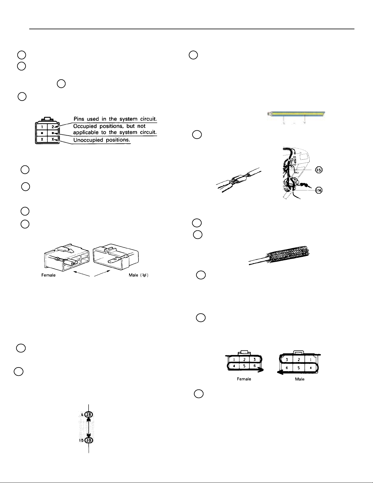
A : System Title
B : Indicates a Relay Block. No shading is used and only the
Relay Block No. is shown to distinguish it from the J/B.
Example: 1 Indicates Relay Block No. 1.
C : Indicates the connector to be connected to a
part (the numeral indicates the pin No.)
Explanation of pin use.
The pins shown are only for the highest grade, or only
include those in the specification.
D : Connector Color Connectors not indicated are milky
white in color:
E : ( ) is used to indicate different wiring and connector, etc.
when the vehicle model, engine type, or specification is
different.
F : Indicates related system.
G : Indicates the wiring harness and wiring harness
connector. The wiring harness with male terminal is
shown with arrows ( ).
v
v
J : Indicates the wiring color.
Wire colors are indicated by an alphabetical code.
B = Black
BR = Brown
G = Green
GR = Gray
L = Black
LG = Light Green
O = Orange
P = Pink
R = Red
V = Violet
W = White
Y = Yellow
The first letter indicates the basic wire color and the second
letter indicates the color of the stripe.
Example: L – Y
(blue) (yellow)
K : Indicates a wiring Splice Point (Codes are “E” for
the Engine Room, “I” for the Instrument Panel,
and “B” for the Body).
Example:
The Location of Splice Point I 5 is indicated by the shaded
section.
L : Page No.
M : Indicates a shielded cable.
The first letter of the code for each wiring harness and wiring
harness connector(s) indicates thecomponent’s location, e.g,
“E” for the Engine Compartment, “I” for the Instrument Panel
and Surrounding area, and “B” for the Body and Surrounding
area.
When more than one code has the first and second letters in
common, followed by numbers (e.g, IH1, IH2), this indicates
the same type of wiring harness and wiring harness connector.
H : Represents a part (all parts are shown in sky
blue). The code is the same as the code used in
parts position.
I : Junction Block (The number in the circle is the
J/B No. and the connector code is shown beside
it). Junction Blocks are shaded to clearly
separate them from other parts (different junction
blocks are shaded differently for further
clarification).
Example:
3B indicates
that it is inside
Junction Block
No. 3.
N : Indicates a ground point.
The first letter of the code for each ground point(s) indicates
the component’s location, e.g. “E” for the Engine
Compartment, “I” for the Instrument Panel and Surrounding
area, and “B” for the Body and Surrounding area.
O : Indicates the pin number of the connector.
The numbering system is different for female and male
connectors.
lower right
lower left
P : When 2 parts both use one connector in common, the parts
connector name used in the wire routing section is shown in
square brackets [ ].
5
B HOW TO USE THIS MANUAL
Q
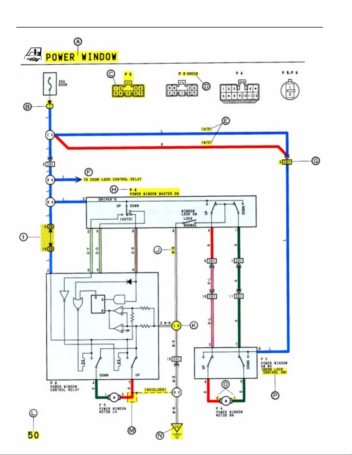
WITH THE IGNITION SW TURNED ON, THE CURRENT FLOWS TO TERMINAL 3 OF THE POWER WINDOW MASTER SW, TERMINAL 2 OF THE POWER WINDOW CONTROL
RELAY AND TERMINAL 8 OF THE POWER WINDOW SW THROUGH THE DOOR FUSE.
1. DRIVER’S WINDOW “MANUAL UP” OPERATION BY MASTER SW
HOLDING MANUAL SW (DRIVER’S) ON “UP” POSITION LOCATED IN POWER WINDOW MASTER SW, THE CURRENT FLOWS TO TERMINAL 5 OF THE POWER WINDOW CONTROL RELAY THROUGH TERMINAL 3 OF THE MASTER SW TERMINAL 2 TO OPERATE A POWER WINDOW CONTROL RELAY. THUS THE CURRENT INSIDE THE RELAY
FLOWS FROM TERMINAL 2 OF THE RELAY TERMINAL 1 TERMINAL 2 OF THE POWER WINDOW MOTOR TERMINAL 1 TERMINAL 4 OF THE RELAY TERMINAL 3 TO GROUND. THE MOTOR TURNS TO ASCENT THE WINDOW. RELEASING THIS SW, THE ROTATION OF MOTOR IS STOPPED AND THE WINDOWS CAN STOP AT
WILL POINT.
(FOR THE “MANUAL DOWN” OPERATION, CURRENT FLOWS IN THE REVERSE DIRECTION BECAUSE THE TERMINALS WHERE IT FLOW ARE CHANGED).
2. DRIVER’S WINDOW “AUTO DOWN” OPERATION BY MASTER SW
ONCE THE “AUTO DOWN” BUTTON OF THE MASTER SW IS PUSHED, THE CURRENT FLOW TERMINAL 9 OF THE POWER WINDOW CONTROL RELAY THROUGH TERMINAL 3
OF THE MASTER SW TERMINALS 8 AND 9 TO OPERATE THE RELAY. THUS THE CURRENT INSIDE THE POWER WINDOW CONTROL RELAY FLOWS FROM TERMINAL 2 OF
THE RELAY TERMINAL 4 TERMINAL 1 OF THE POWER WINDOW MOTOR TERMINAL 2 TERMINAL 1 OF THE RELAY TERMINAL 3 TO GROUND. THE
MOTOR CONTINUES THE ROTATION ENABLING TO DESCENT THE WINDOW.
THE WINDOW DESCENDS TO THE END POSITION. THE CURRENT WILL BE CUT OFF TO RELEASE THE AUTO DOWN FUNCTION BASED ON THE INCREASING CURRENT
BETWEEN TERMINAL 2 OF THE RELAY AND TERMINAL 1 IN RELAY.
3. DRIVER’S WINDOW AUTO DOWN RELEASE OPERATION BY MASTER SW
HOLDING THE MANUAL SW (DRIVER’S) ON “UP” POSITION IN OPERATING AUTO DOWN. THE CURRENT FROM TERMINAL 3 OF THE MASTER SW PASSING TERMINAL 2
FLOWS TERMINAL 5 OF THE RELAY AND RELEASES THE AUTO DOWN FUNCTION IN THE POWER WINDOW CONTROL RELAY. RELEASING THE HAND FROM SW, WINDOW
STOPS AND CONTINUING ON TOUCHING SW. THE FUNCTION SWITCHES TO MANUAL UP OPERATION.
4. PASSENGER’S WINDOW UP OPERATION (MASTER SW) AND WINDOW LOCK SW OPERATION
HOLDING PASSENGER’S WINDOW SW (MASTER SW) ON “UP”, THE CURRENT FLOWS FROM TERMINAL 3 OF THE MASTER SW PASSING TERMINAL 6 TO TERMINAL 3 OF THE
POWER WINDOW SW (PASSENGER’S) TERMINAL 4 TERMINAL 2 OF THE MOTOR TERMINAL 1 TERMINAL 9 OF THE POWER WINDOW SW TERMINAL 7
TERMINAL 1 OF THE MASTER SW TERMINAL 4 TO GROUND. THE MOTOR RUNS TO ASCENT THE WINDOW. RELEASING THIS SW, THE ROTATION OF MOTOR IS
STOPPED AND WINDOW CAN STOP AT WILL PLACE. SWITCHING THE WINDOW LOCK SW IN “LOCK” POSITION, THE CIRCUIT IS OPENED AND STOPPED THE MOTOR ROTATION.
(FOR THE DOWN OPERATION, CURRENT FLOWS IN THE REVERSE DIRECTION BECAUSE THE TERMINALS WHERE IT FLOWS ARE CHANGED).
R
P 2 POWER WINDOW CONTROL RELAY
3–GROUND: ALWAYS CONTINUITY
2–GROUND: APPROX. 12 VOLTS WITH THE IGNITION SW AT ON POSITION
5–GROUND: APPROX. 12 VOLTS WITH THE IGNITION SW AT ON POSITION AND THE MASTER SW AT UP POSITION
8–GROUND: APPROX. 12 VOLTS WITH THE IGNITION SW AT ON POSITION AND THE MASTER SW AT AUTO DOWN POSITION
9–GROUND: APPROX. 12 VOLTS WITH THE IGNITION SW AT ON POSITION AND THE MASTER SW AT DOWN OR AUTO DOWN POSITION
P 4 POWER WINDOW MASTER SW
4–GROUND: ALWAYS CONTINUITY
3–GROUND: APPROX. 12 VOLTS WITH THE IGNITION SW AT ON POSITION
WINDOW LOCK SW
OPEN WITH THE WINDOW LOCK SW AT LOCK POSITION
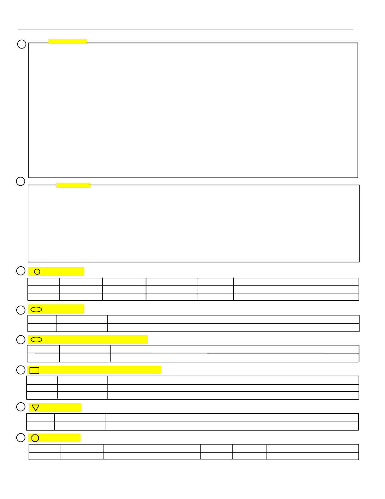
S
SYSTEM OUTLINE
SERVICE HINTS
: PARTS LOCATION
CODE SEE PAGE CODE SEE PAGE CODE SEE PAGE
P2 21 P4 21 P6 21
P3 21 P5 21
T
: RELAY BLOCKS
CODE SEE PAGE RELAY BLOCK (RELAY BLOCK LOCATION)
1 16 R/B NO. 1 (INSTRUMENT PANEL LEFT)
U
: JUNCTION BLOCK AND WIRE HARNESS CONNECTOR
CODE SEE PAGE JUNCTION BLOCK AND WIRE HARNESS (CONNECTOR LOCATION)
38 14 J/B NO. 3 AND COWL WIRE (INSTRUMENT PANEL LEFT SIDE)
V
: CONNECTOR JOINING WIRE HARNESS AND WIRE HARNESS
CODE SEE PAGE JOINING WIRE HARNESS AND WIRE HARNESS (CONNECTOR LOCATION)
ID1 26 FRONT DOOR RH WIRE AND COWL WIRE (RIGHT KICK PANEL)
IH1 26 FRONT DOOR LH WIRE AND COWL WIRE (LEFT KICK PANEL)
W
: GROUND POINTS
CODE SEE PAGE GROUND POINT LOCATION
IC 24 COWL LEFT
X
: SPLICE POINTS
CODE SEE PAGE WIRE HARNESS WITH SPLICE POINTS CODE SEE PAGE WIRE HARNESS WITH SPLICE POINTS
I 5 24 COWL WIRE
6
B
Q : Explains the system outline.
R : Indicates values or explain the function for reference during troubleshooting.
S : Indicates the reference page showing the position on the vehicle of the parts in the system circuit.
Example: Part “P 4” (Power Window Master SW) is on page 21 of the manual.
* The letter in the code is from the first letter of the part, and the number indicates its order in
parts starting with the letter.
Example: P 4
Part is 4th in order
Power Window Master SW
T : Indicates the reference page showing the position on the vehicle of Relay Block Connectors in the system
circuit.
Example: Connector “1” is described on page 16 on this manual and is installed on the left side of the
instrument panel.
U : Indicates the reference page showing the position on the vehicle of J/B and Wire Harness in the system
circuit.
Example: Connector “3B”connects the Cowl Wire and J/B No. 3. It is described on page 14 of this manual,
and is installed on the instrument panel left side.
V : Indicates the reference page describing the wiring harness and wiring harness connector (the female wiring
harness is shown first, followed by the male wiring harness).
Example: Connector “ID1”connects the front door RH wire (female) and cowl wire (male). It is described
on page 26 of this manual, and is installed on the right side kick panel.
W : Indicates the reference page showing the position of the ground points on the vehicle.
Example: Ground point “IC” is described on page 24 of this manual and is installed on the cowl left side.
X : Indicates the reference page showing the position of the splice points on the vehicle.
Example: Splice point “I 5” is on the Cowl Wire Harness and is described on page 24 of this manual.
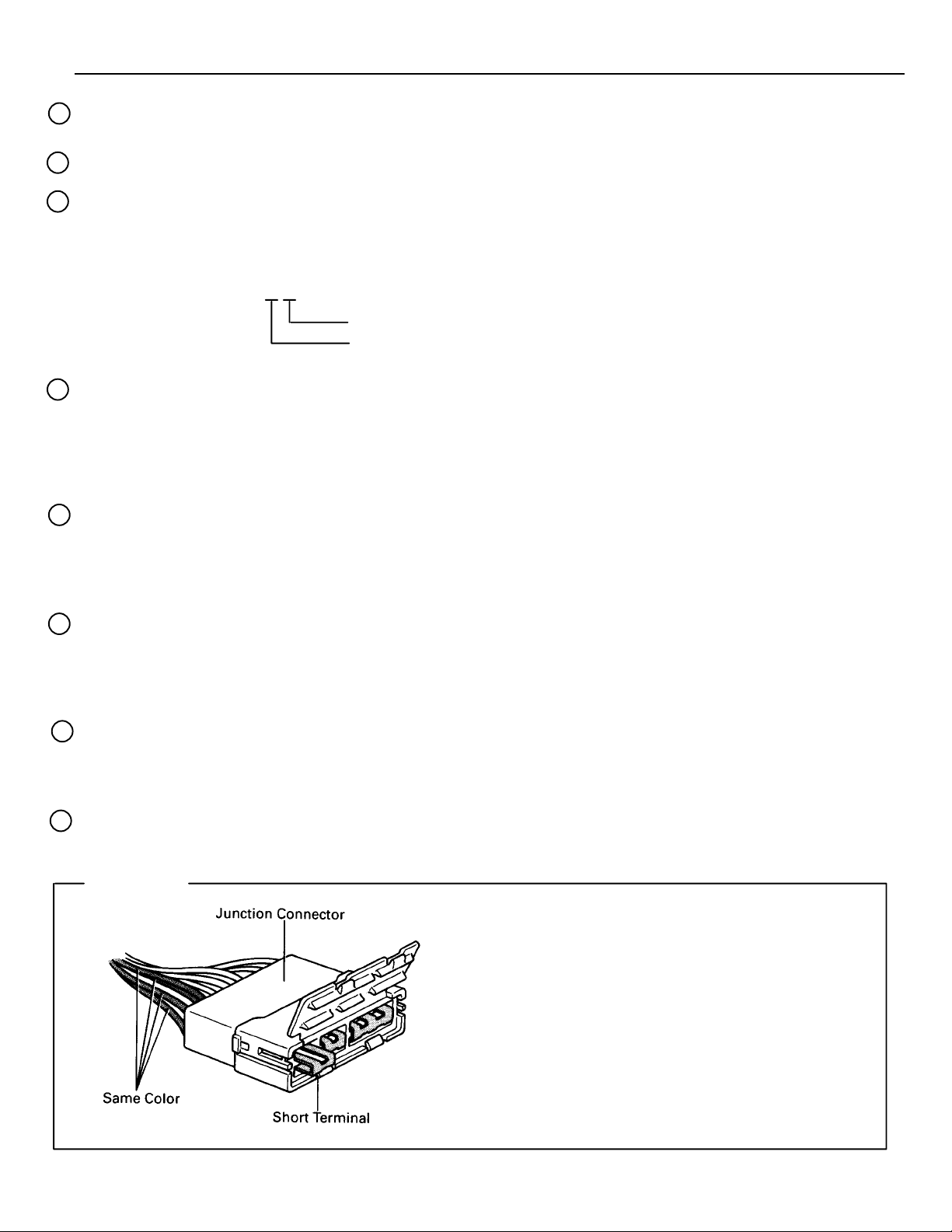
HINTS:
Junction connector (code: J1 to J19) in this manual
include a short terminal which is connected to a
number of wire harnesses. Always perform inspection with the short terminal installed. (When installing the wire harnesses, the harnesses can be connected to any position within the short terminal
grouping. Accordingly, in other vehicles, the same
position in the short terminal may be connected to
a wire harness from a different part.)
Wire harness sharing the same short terminal
grouping have the same color.
7
B HOW TO USE THIS MANUAL
The “Current Flow Chart” section, describes which parts each power source (fuses, fusible links, and circuit
breakers) transmits current to. In the Power Source circuit diagram, the conditions when battery power is
supplied to each system are explained. Since all System Circuit diagrams start from the power source, the power
source system must be fully understood.
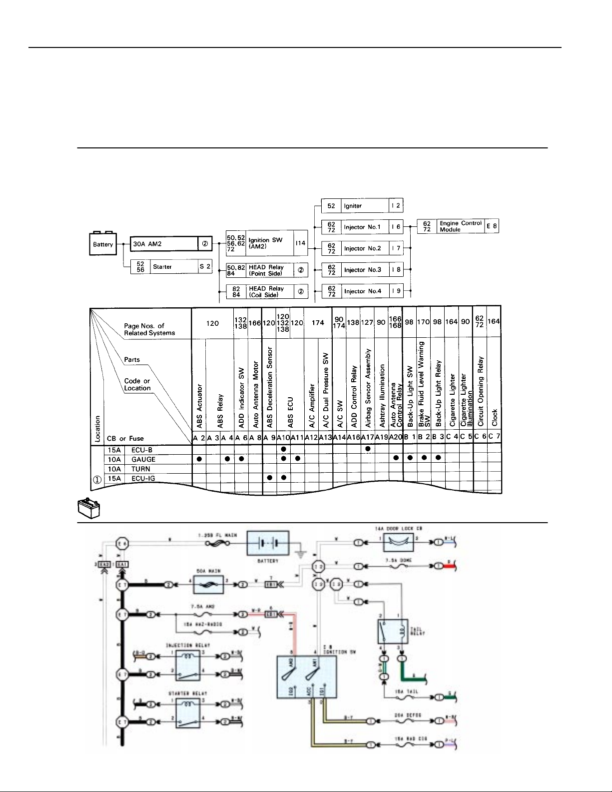
H POWER SOURCE (CURRENT FLOW CHART)
The chart below shows the route by which current flows from the battery to each electrical source (Fusible Link, Circuit Breaker, Fuse,
etc.) and other parts.
The next page and following pages shown the parts to which each electrical source outputs current.
8
POWER SOURCE
* The system shown here is an EXAMPLE ONLY. It is different to the actual circuit shown in the SYSTEM CIRCUITS SECTION.
B
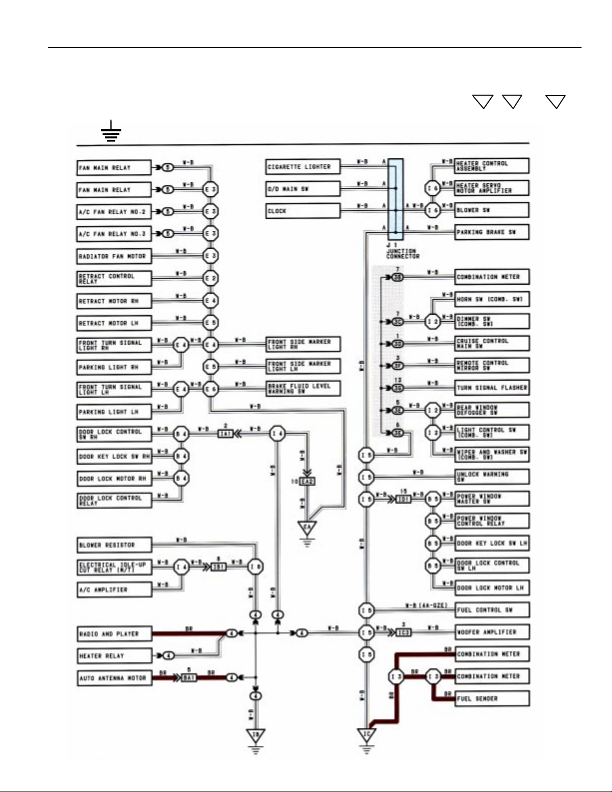
The ground points circuit diagram shows the connections from all major parts to the respective ground points.
When troubleshooting a faulty ground point, checking the system circuits which use a common ground may
help you identify the problem ground quickly. The relationship between ground points ( , and
EA
IB
IC
shown below) can also be checked this way.
J GROUND POINT
* The system shown here is an EXAMPLE ONLY. It is different to the actual circuit shown in the SYSTEM CIRCUITS SECTION.
9
C TROUBLESHOOTING
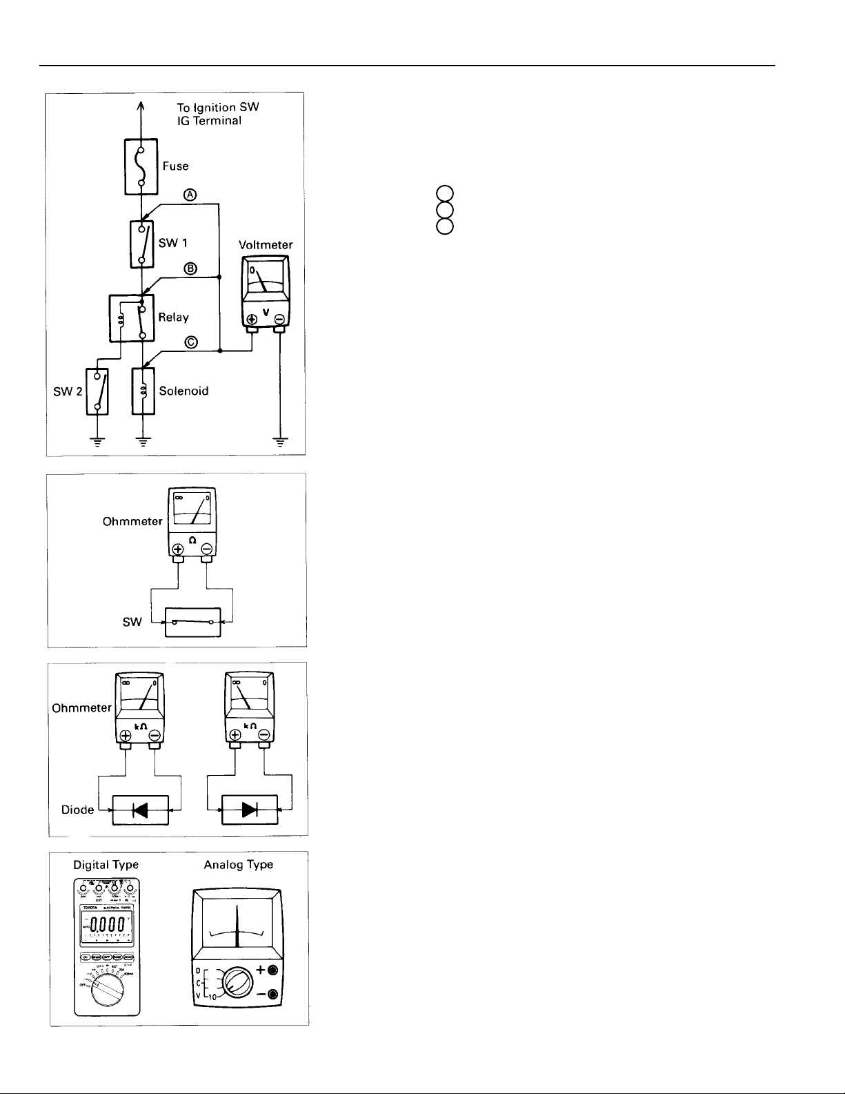
VOLTAGE CHECK
(a) Establish conditions in which voltage is
check point.
Example:
A – Ignition SW on
B – Ignition SW and SW 1 on
C – Ignition SW, SW 1 and Relay on (SW2 off)
(b) Using a voltmeter, connect the negative lead to a
ground point or negative battery terminal, and a
positive lead to the connector or component terminal.
This check can be done with a test light instead of a
voltmeter.
CONTINUITY AND RESISTANCE CHECK
(a) Disconnect the battery terminal or wire so there is no
voltage between the check points.
(b) Contact the two leads of an ohmmeter to each of the
check point.
If the circuit has diodes, reverse the two leads and check
again.
When contacting the negative lead to the diode positive side
and the positive lead to the negative side, there should be
continuity.
When contacting the two leads in reverse, there should be
no continuity.
(c) Use the volt/ohmmeter with high impedance (10kΩ/V
minimum) for troubleshooting of the electrical circuit.
10
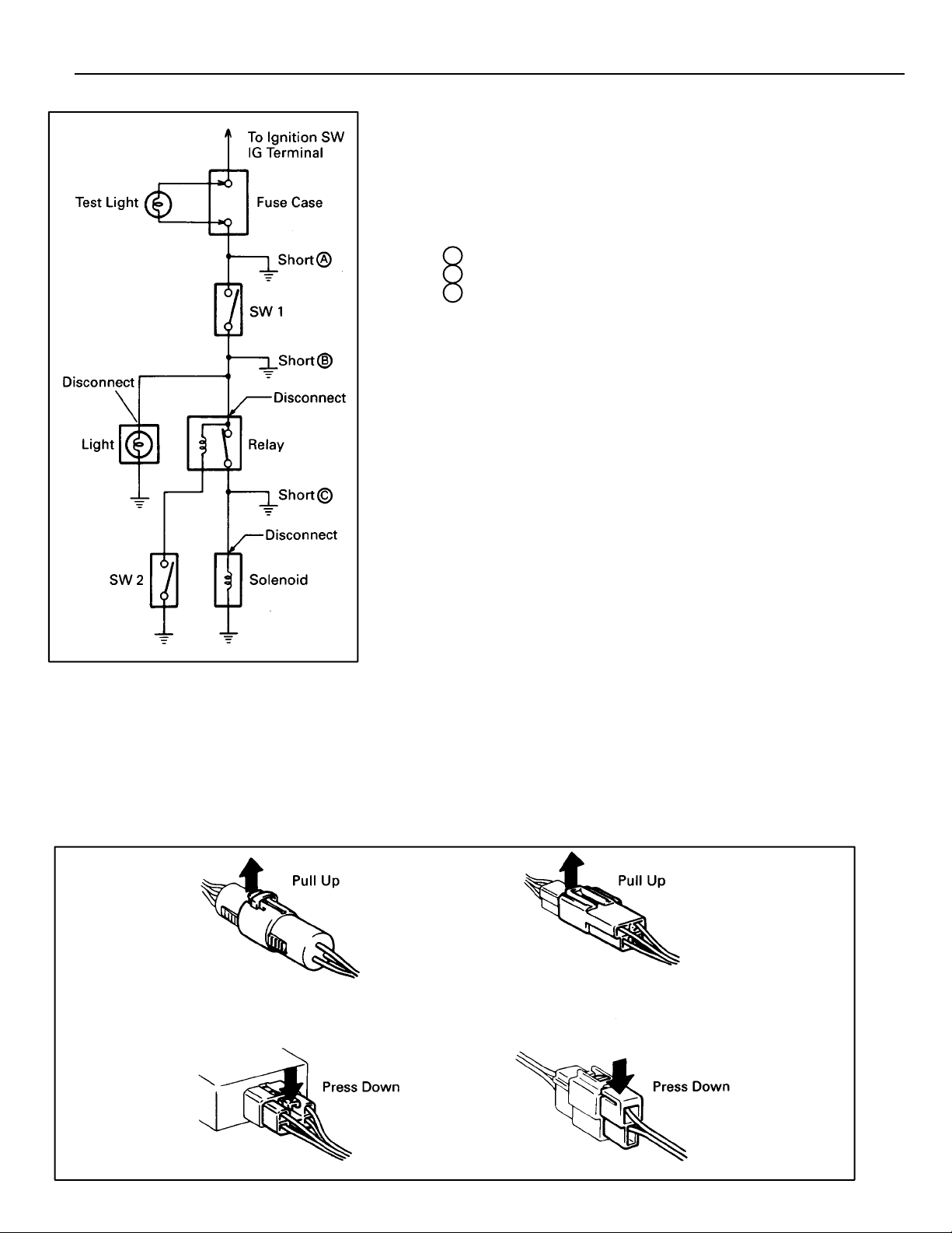
FINDING A SHORT CIRCUIT
(a) Remove the blown fuse and disconnect all loads of the
fuse.
(b) Connect a test light in place of the fuse.
(c) Establish conditions in which the test light comes on.
Example:
A – Ignition SW on
B – Ignition SW and SW 1 on
C – Ignition SW, SW 1 and Relay on (Connect the
Relay) and SW 2 off (or Disconnect SW 2)
(d) Disconnect and reconnect the connectors while watching
the test light.
The short lies between the connector where the test
light stays lit and the connector where the light goes
out.
(e) Find the exact location of the short by lightly shaking
the problem wire along the body.
CAUTION:
C
(a) Do not open the cover or the case of the ECU unless
absolutely necessary. (If the IC terminals are touched,
the IC may be destroyed by static electricity.)
(b) When replacing the internal mechanism (ECU part) of
the digital meter, be careful that no part of your body
or clothing comes in contact with the terminals of
leads from the IC, etc. of the replacement part (spare
part).
DISCONNECTION OF MALE AND FEMALE
CONNECTORS
To pull apart the connectors, pull on the connector itself, not the
wire harness.
HINT: Check to see what kind of connector you are disconnecting
before pulling apart.
11
C TROUBLESHOOTING
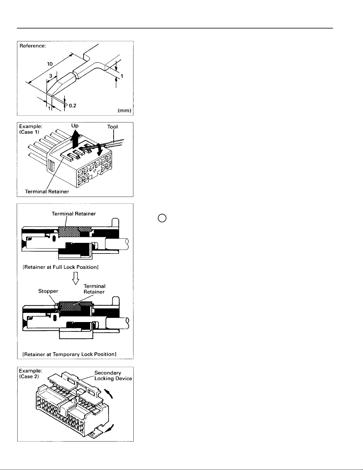
HOW TO REPLACE TERMINAL
(with terminal retainer or secondary locking
device)
1. PREPARE THE SPECIAL TOOL
HINT: To remove the terminal from the connector, please
construct and use the special tool or like object shown
on the left.
2. DISCONNECT CONNECTOR
3. DISENGAGE THE SECONDARY LOCKING DEVICE OR
TERMINAL RETAINER
(a) Locking device must be disengaged before the terminal
locking clip can be released and the terminal removed
from the connector.
(b) Use a special tool or the terminal pick to unlock the
secondary locking device or terminal retainer.
NOTICE:
Do not remove the terminal retainer from connector body.
A For Non–Waterproof Type Connector
HINT: The needle insertion position varies according to
the connector’s shape (number of terminals
etc.), so check the position before inserting it.
“Case 1”
Raise the terminal retainer up to the temporary
lock position.
12
“Case 2”
Open the secondary locking device.
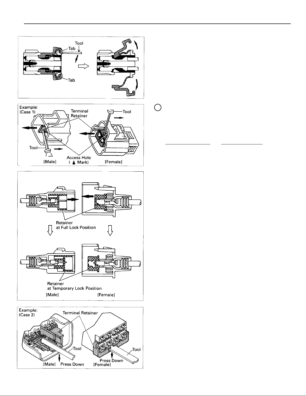
For Waterproof Type Connector
B
HINT: Terminal retainer color is different
according to connector body.
Example:
Terminal Retainer
Black or White :Gray
Black or White :Dark Gray
Gray or White :Black
:Connector Body:
C
“Case 1”
Type where terminal retainer is
pulled up to the temporary lock
position (Pull Type).
Insert the special tool into the
terminal retainer access hole (Mark)
and pull the terminal retainer up to
the temporary lock position.
HINT: The needle insertion position varies
according to the connector’s shape
(number of terminals etc.), so check
the position before inserting it.
“Case 2”
Type which cannot be pulled as far as
Power Lock insert the tool straight
into the access hole of terminal
retainer as shown.
13
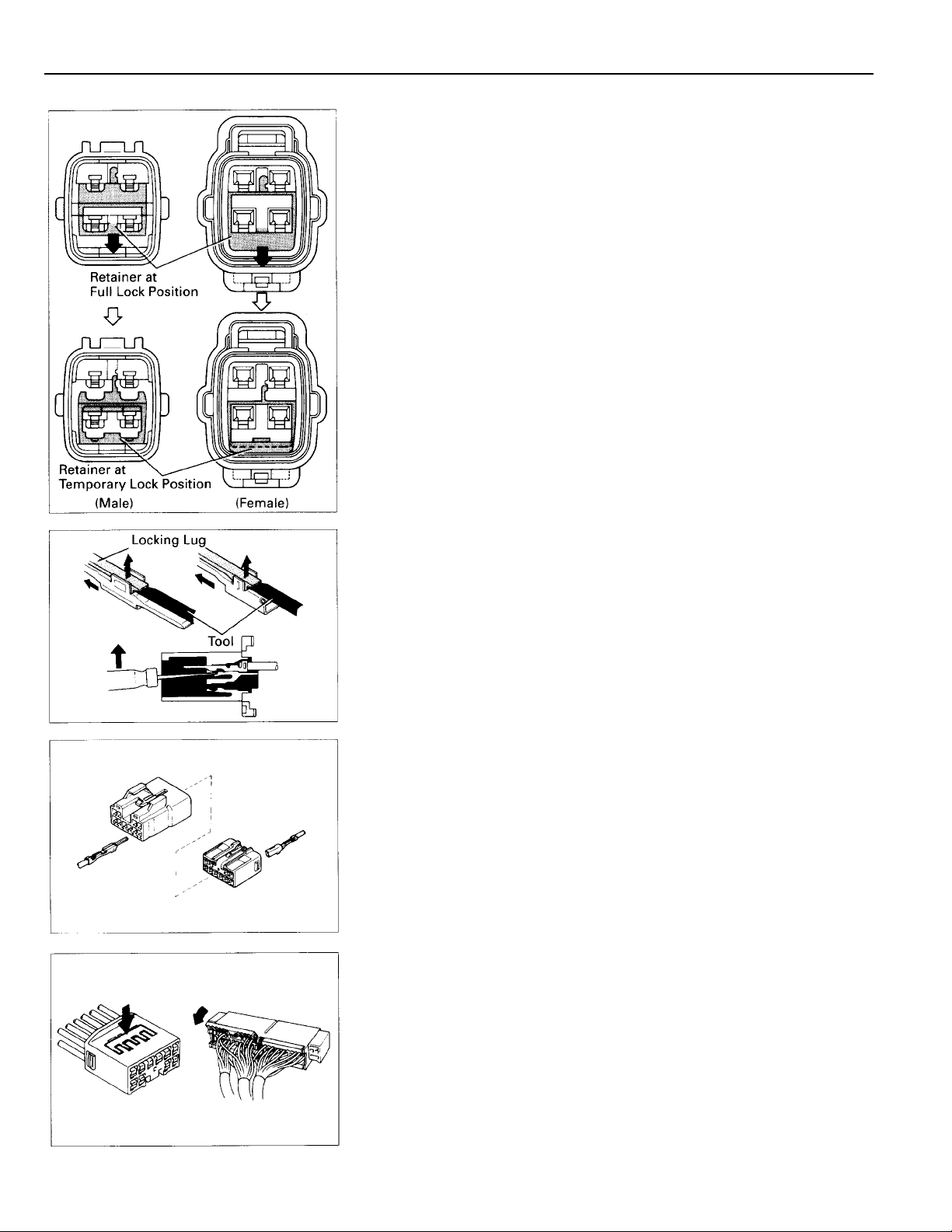
C TROUBLESHOOTING
Push the terminal retainer down to the temporary lock
position.
(c) Release the locking lug from terminal and pull the
terminal out from rear.
4. INSTALL TERMINAL TO CONNECTOR
(a) Insert the terminal.
HINT:
1. Make sure the terminal is positioned correctly.
2. Insert the terminal until the locking lug locks firmly.
3. Insert the terminal with terminal retainer in the
temporary lock position.
(b) Push the secondary locking device or terminal retainer
into the full lock position.
14
5. CONNECT CONNECTOR

ABBREVIATIONS
T
he following abbreviations are used in this manual.
ABS = Anti–Lock Brake System
A/C = Air Conditioning
ACIS = Acoustic Control Induction System
A/T = Automatic Transaxle
CD = Compact Disc
COMB. = Combination
ECU = Electronic Control Unit
EGR = Exhaust Gas Recirculation
ESA = Electronic Spark Advance
EVAP = Evaporative Emission
FL = Fusible Link
J/B = Junction Block
ABBREVIATIONS D
LH = Left–Hand
O/D = Overdrive
R/B = Relay Block
RH = Right–Hand
SFI = Sequential Multiport Fuel Injection
SRS = Supplemental Restraint System
SW = Switch
TEMP. = Temperature
TRAC = Traction Control
VSV = Vacuum Switching Valve
w/ = With
w/o = Without
* The titles given inside the components are the names of the terminals (terminal codes) and are
not treated as being abbreviations.
15
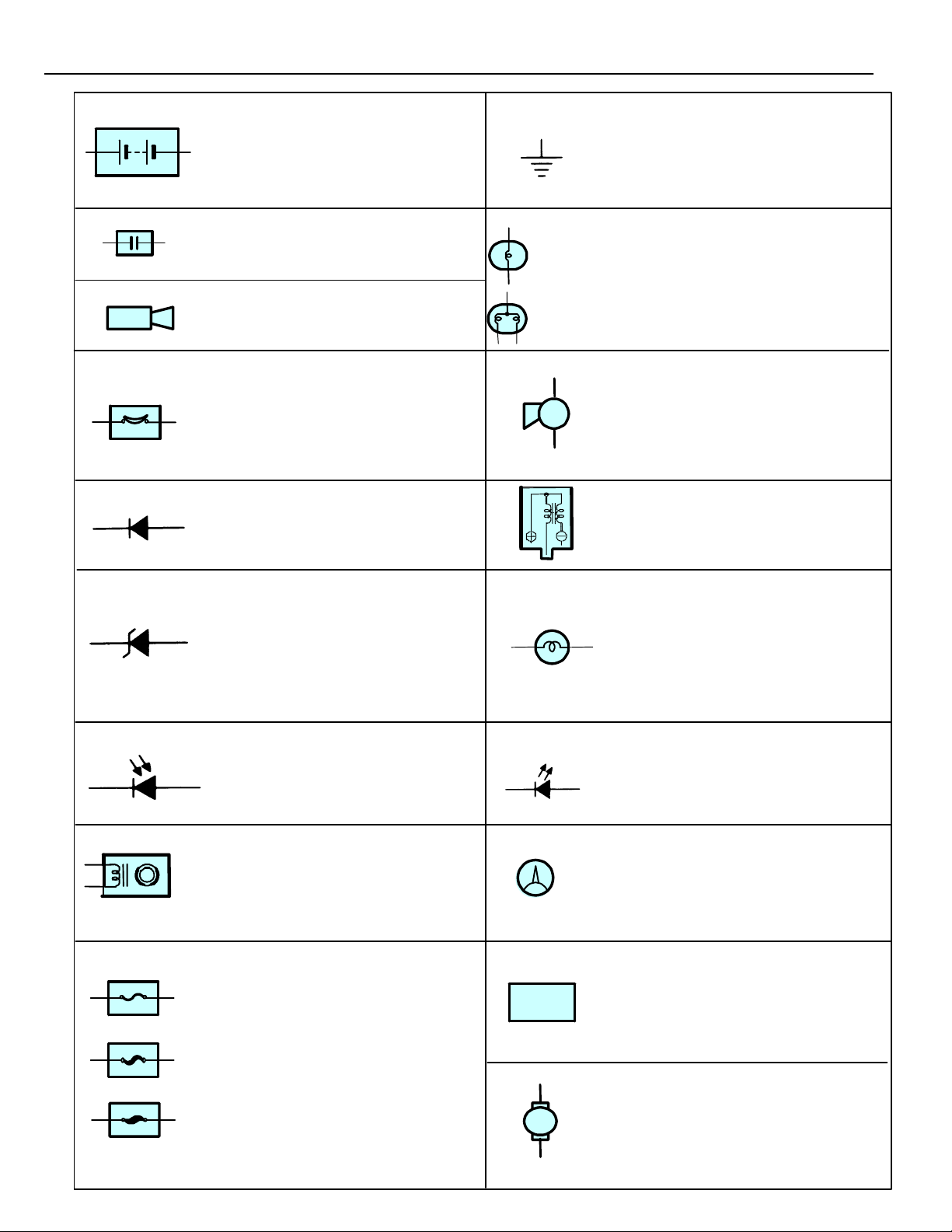
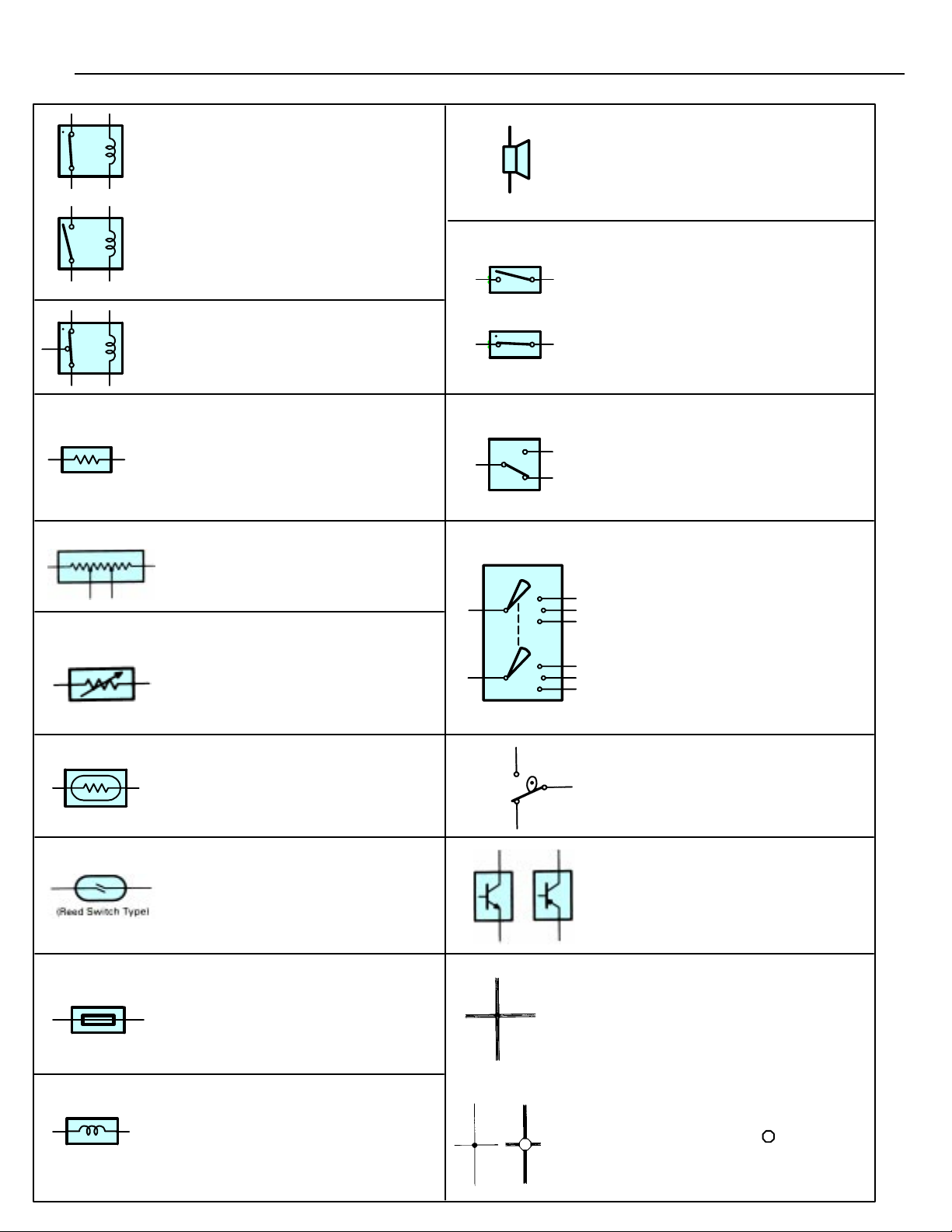
E GLOSSARY OF TERMS AND SYMBOLS
BATTERY
Stores chemical energy and
converts it int o e l e c trical energy.
Provides DC current for the
auto’s various electrical circuits.
CAPACITOR (Condenser)
A small holding unit for temporary
storage of electrical voltage.
CIGARETTE LIGHTER
An electric resistance heating
element.
CIRCUIT BREAKER
Basically a reusable fuse, a circuit
breaker will heat and open if too
much current flows through it.
Some units automatically reset when
cool, others must be manually reset.
DIODE
A semiconductor which allows
current flow in only one direction.
HEADLIGHTS
1. SINGLE
FILAMENT
2. DOUBLE
FILAMENT
GROUND
The point at which wiring attaches
to the Body, thereby providing a
return path for an electrical circuit;
without a ground, current cannot
flow.
Current flow causes a headlight
filament to heat up and emit light.
A headlight may have either a
single (1) filament or a double (2)
filament.
HORN
An electric device which sounds a
loud audible signal.
IGNITION COIL
Convert low–voltage DC current
into high–voltage ingition current
for firing the spark plugs.
(for Medium Current Fuse)
(for High Current Fuse or
Fusible Link.)
16
DIODE, ZENER
A diode which allows current
flow in one direction but blocks
reverse flo w o n l y u p to a specific
voltage. Above that potential, it
passes the excess voltage.
This acts as a simple voltage
regulator.
PHOTODIODE
The photodiode is a
semiconductor which controls the
current flow according to the
amount of light.
DISTRIBUTOR, IIA
Channels high–voltage current
from the ignition coil to the
individual spark plugs.
FUSE
A thin metal strip which burns
through when too much current
flows through it, thereby stop–
ping current flow and protecting a
circuit from damage.
FUSIBLE LINK
A heavy–gauge wire placed in
high amperage circuits which
burns through on overloads,
thereby protecting the circuit.
The numbers indicate the cross–
section surface area of the wires.
FUEL
M
LIGHT
Current flow through a filament
causes the filament to heat up
and emit light.
LED (LIGHT EMITTING DIODE)
Upon current flow, these diodes
emit light without producing the
heat of a comparable light.
METER, ANALOG
Current flow activates a magnetic
coil which causes a needle to
move, thereby providing a relative
display against a background
calibration.
METER, DIGITAL
Current flow activates one or
many LED’s, LCD’s, or fluoresent
displays, which provide a relative
or digital display.
MOTOR
A power unit which converts
electrical energy into mechanical
energy, especially rotary motion.
E
RELAY
1. NORMALLY
CLOSED
Basically, an electrically
operated switch which
may be normally closed
(1) or open (2). Current
flow through a small
2. NORMALLY
OPEN
coil creates a magnetic
field which either opens
or closes an attached
switch.
RELAY, DOUBLE THROW
A relay which passes current
through one set of contacts or the
other.
RESISTOR
An electrical component with a
fixed resistance, placed in a circuit
to reduce voltage to a specific
value.
RESISTOR, TAPPED
A resistor which supplies two or
more different non adjustable
resistance values.
RESISTOR, VARIABLE or
RHEOSTAT
A controllable resistor with a
variable rate of resistance.
Also called a potentiometer or
rheostat.
SPEAKER
An electromechanical device
which creates sound waves from
current flow.
SWITCH, MANUAL
1. NORMALLY
OPEN
Open and
closes circuits,
thereby
stopping (1) or
allowing (2)
2. NORMALLY
CLOSED
current flow.
SWITCH, DOUBLE THROW
A switch which continuously
passes cureent through one set of
contacts or the other.
SWITCH,
IGNITION
A key operated switch with several
positions which allows various
circuits, particularly the primary
ignition circuit, to become
operational.
SENSOR (Thermistor)
A resistor which varies its
resistance with temperature.
SENSOR, SPEED
Uses magnetic impulses to open
and close a switch to create a
signal for activation of other
components.
SHORT PIN
Used to provide an unbroken
connection within a juction block.
SOLENOID
An electromagnetic coil which
forms a magnetic field when
current flows, to move a plunger,
etc.
SWITCH, WIPER PARK
TRANSISTOR
WIRES
(1) NOT
CONNECTED
(2) SPLICED
Automatically returns wipers to
the stop position when the wiper
switch is turned off.
A solid state device typically used
as an electronic relay; stops or
passes current depending on the
voltage applied at “base.”
Wires are always
drawn as straight lines
on wiring diagrams.
Crossed wires (1)
without a black dot at
the junction are not
joined;
crossed wires (2) and
a black dot or
octagonal ( ) mark at
the juction as spliced
(joined) connections.
17
+
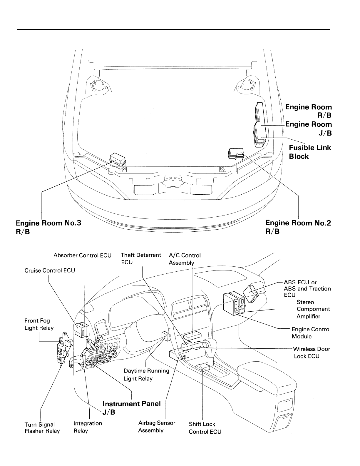
F RELAY LOCATIONS
[Engine Compartment]
[Instrument Panel]
18
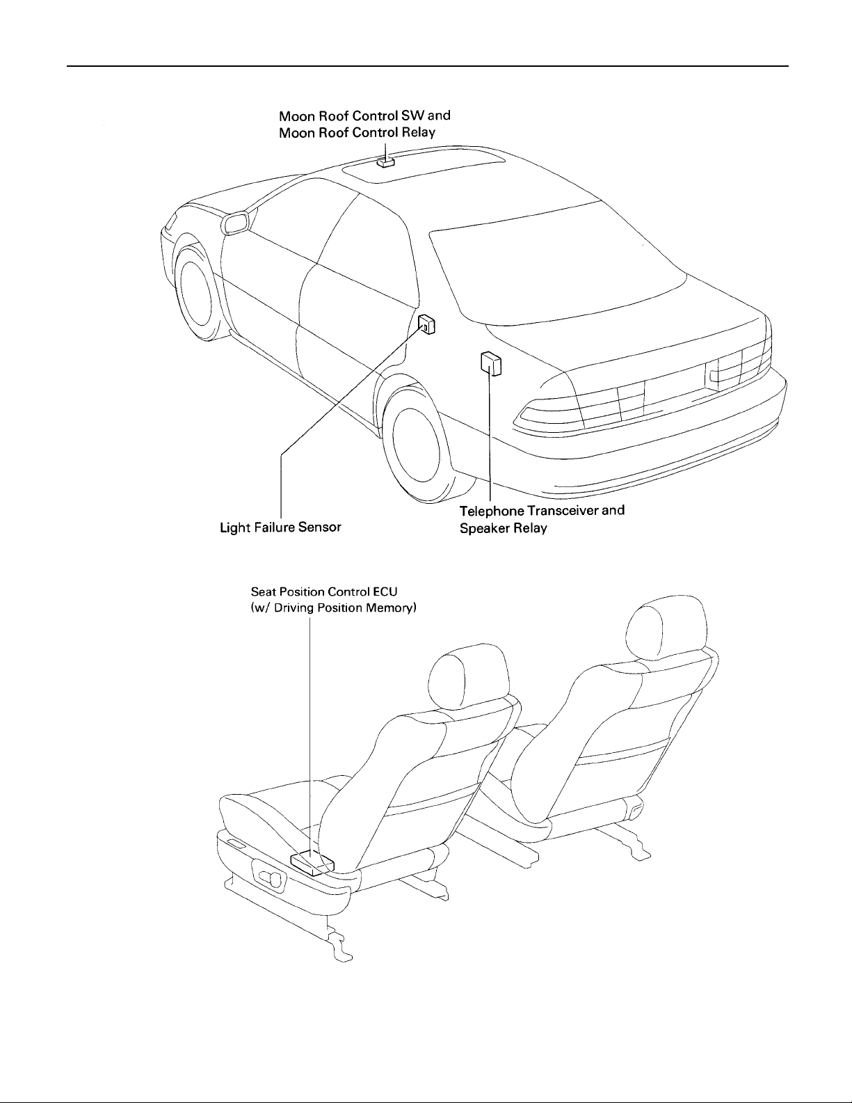
(Body)
F
[Seat]
19
F RELAY LOCATIONS
,
,,,
,,
: Engine Room J/B Engine Compartment Left (See Page 18)
20
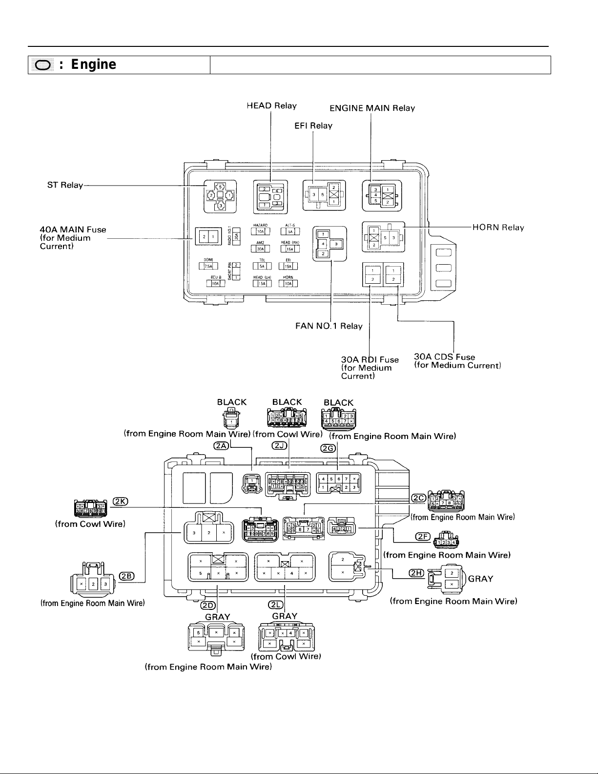
(Engine Room J/B Inner Circuit)
F
21
F RELAY LOCATIONS
R/B
Fusible Link Block
1
: Engine Room
Engine Compartment Left (See Page 18)
(Inside Engine Room J/B)
Engine Compartment Left (See Page 18)
(Inside Engine Room J/B)
22
2
: Engine Room No. 2 R/B Engine Compartment Left (See Page 18)
(Canada)
F
3
: Engine Room No.3 R/B Radiator Upper Support RH (See Page 18)
23
F RELAY LOCATIONS
,
,,,
,,
: Instrument Panel J/B Lower Finish Panel (See Page 18)
24
(Instrument Panel J/B Inner Circuit)
F
25
2 6
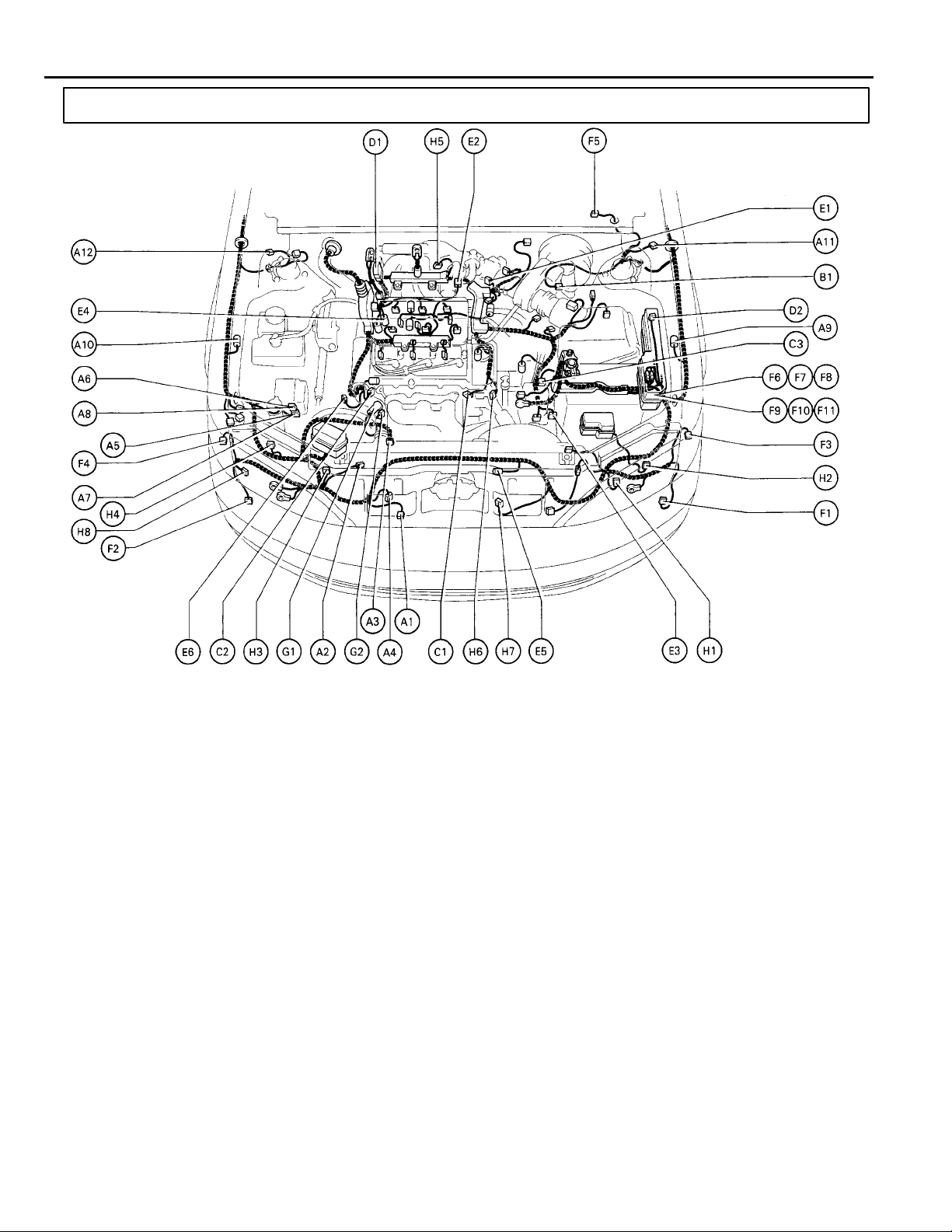
G ELECTRICAL WIRING ROUTING
Position of Parts in Engine Compartment
A 1 Ambient Temp. Sensor
A 2 A/C Condenser Fan Motor
A 3 A/C Magnetic Clutch and Lock Sensor
A 4 A/C Triple Pressure SW (A/C Dual and
Single Pressure SW)
A 5 ABS Actuator
A 6 ABS Actuator
A 7 ABS and Traction Actuator
A 8 ABS and Traction Actuator
A 9 ABS Speed Sensor Front LH
A 10 ABS Speed Sensor Front RH
A 11 Absorber Control Acuator Front LH
A 12 Absorber Control Acuator Front RH
B 1 Brake Fluid Level Warning SW
C 1 Camshaft Position Sensor
C 2 Crankshaft Position Sensor
C 3 Cruise Control Actuator
D 1 Data Link Connector 1
D 2 Diode (A/C)
E 1 EGR Gas Temp. Sensor
E 2 EGR Valve Position Sensor
E 3 Electronically Controlled Transmission
Solenoid
E 4 Engine Coolant Temp. Sensor
E 5 Engine Hood Courtesy SW
E 6 Engine Oil Level Warning SW
26
F 1 Front Fog Light LH
F 2 Front Fog Light RH
F 3 Front Turn Signal and Front Parking Light LH
F 4 Front Turn Signal and Front Parking Light RH
F 5 Front Wiper Motor
F 6 Fusible Link Block
F 7 Fusible Link Block
F 8 Fusible Link Block
F 9 Fusible Link Block
F 10 Fusible Link Block
F 11 Fusible Link Block
G 1 Generator
G 2 Generator
H 1 Headlight LH (HI)
H 2 Headlight LH (LO)
H 3 Headlight RH (HI)
H 4 Headlight RH (LO)
H 5 Heated Oxygen Sensor (Bank 1 Sensor 1)
H 6 Heated Oxygen Sensor (Bank 2 Sensor 1)
H 7 Horn LH
H 8 Horn RH
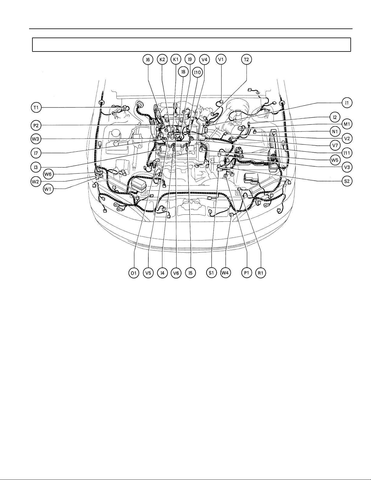
Position of Parts in Engine Compartment
G
I 1 Idle Air Control Valve
I 2 Igniter
I 3 Ignition Coil No. 1
I 4 Ignition Coil No. 2
I 5 Ignition Coil No. 3
I 6 Injector No. 1
I 7 Injector No. 2
I 8 Injector No. 3
I 9 Injector No. 4
I 10 Injector No. 5
I 11 Injector No. 6
K 1 Knock Sensor 1
K 2 Knock Sensor 2
M 1 Mass Air Flow Meter
N 1 Noise Filter (Ignition)
O 1 Oil Pressure SW
P 1 Park/Neutral Position SW,A/T Indicator
Light SW and Back–Up Light SW
P 2 Power Steering Oil Pressure SW
R 1 Radiator Fan Motor
S 1 Starter
S 2 Starter
T 1 Theft Deterrent Horn
T 2 Throttle Position Sensor
V 1 Vapor Pressure Sensor
V 2 Vehicle Speed Sensor (Combination Meter)
V 3 Vehicle Speed Sensor
(Electronically Controlled Transmission)
V 4 VSV (EGR)
V 5 VSV (EVAP)
V 6 VSV (Intake Air Control)
V 7 VSV (Vapor Pressure Sensor)
W 1 Water Level Warning SW
W 2 Washer Motor
W 3 Water Temp. Sender
W 4 Water Temp. SW No.1
W 5 Water Temp. SW No.2
W 6 Wireless Door Lock Buzzer
27
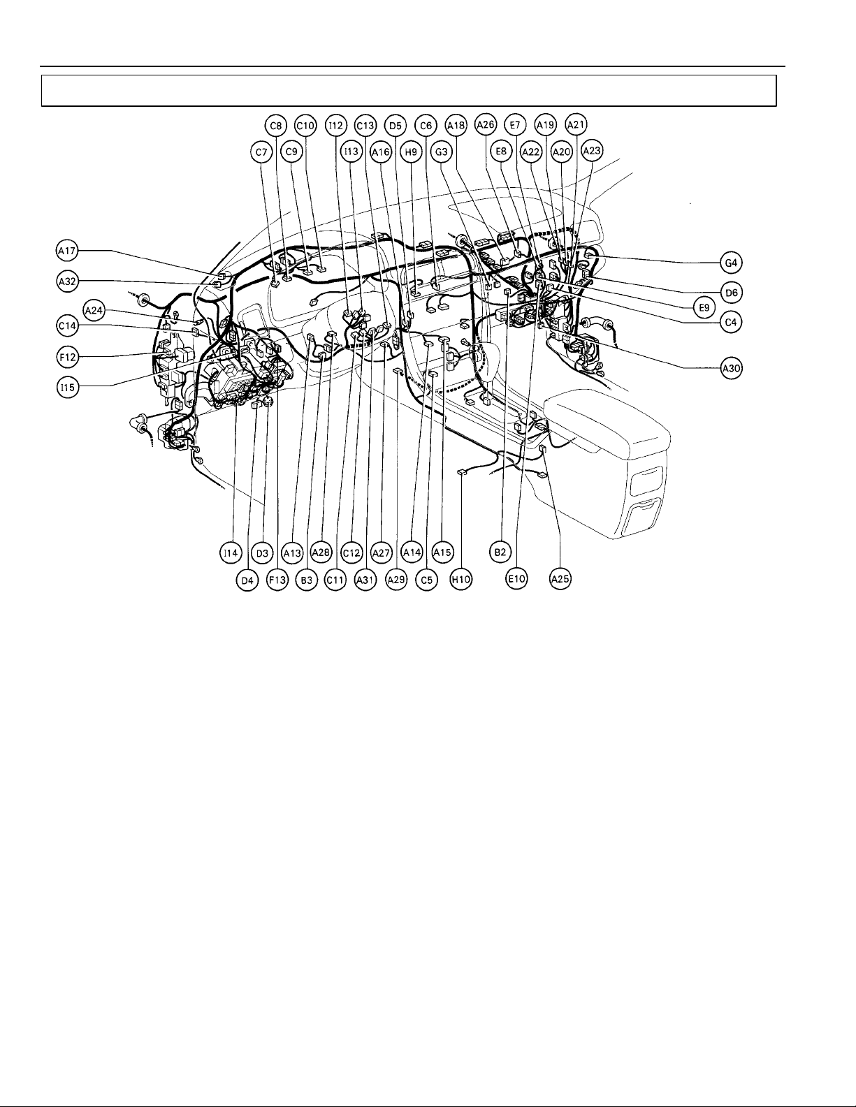
G ELECTRICAL WIRING ROUTING
Position of Parts in Instrument Panel
A 13 A/C Blower Motor Linear Controller
A 14 A/C Control Assembly
A 15 A/C Control Assembly
A 16 A/C Room Temp. Sensor
A 17 A/C Solar Sensor
A 18 A/C Thermistor
A 19 ABS and Traction ECU
A 20 ABS and Traction ECU
A 21 ABS and Traction ECU
A 22 ABS ECU
A 23 ABS ECU
A 24 Absorber Control ECU
A 25 Absorber Control SW
A 26 Air Inlet Control Servo Motor
A 27 Air Mix Control Servo Motor
A 28 Air Vent Mode Control Servo Motor
A 29 Airbag Sensor Assembly
A 30 Airbag Squib (Front Passenger Airbag Assembly)
A 31 Airbag Squib (Steering Wheel Pad)
A 32 Automatic Light Control Sensor
B 2 Blower Motor
B 3 Blower Resistor
C 4 CD Automatic Changer
C 5 Cigarette Lighter
C 6 Clock
C 7 Combination Meter
C 8 Combination Meter
C 9 Combination Meter
26
C 10 Combination Meter
C 11 Combination SW
C 12 Combination SW
C 13 Combination SW
C 14 Cruise Control ECU
D 3 Data Link Connector 2
D 4 Data Link Connector 3
D 5 Daytime Running Light Relay (Main)
D 6 Diode (Courtesy)
E 7 Engine Control Module
E 8 Engine Control Module
E 9 Engine Control Module
E 10 Engine Control Module
F 12 Front Fog Light Relay
F 13 Fuel Lid and Luggage Compartment
Door Opener SW
G 3 Generator Box Light
G 4 Generator Box Light SW
H 9 Hazard SW
H 10 Heated Oxygen Sensor (Bank 1 Sensor 2)
I 12 Ignition Key Cylinder Light
I 13 Ignition SW
I 14 Integration Relay
I 15 Integration Relay
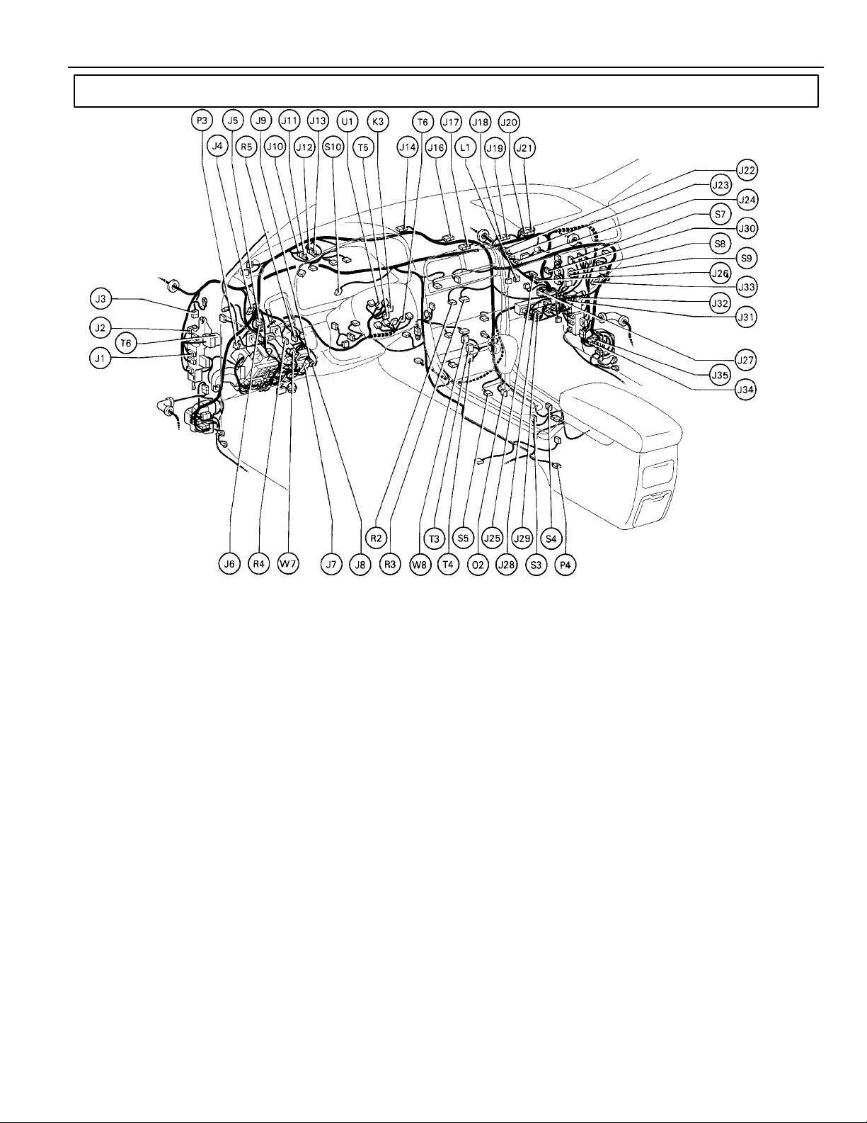
Position of Parts in Instrument Panel
G
J 1 Junction Connector
J 2 Junction Connector
J 3 Junction Connector
J 4 Junction Connector
J 5 Junction Connector
J 6 Junction Connector
J 7 Junction Connector
J 8 Junction Connector
J 9 Junction Connector
J 10 Junction Connector
J 11 Junction Connector
J 12 Junction Connector
J 13 Junction Connector
J 14 Junction Connector
J 15 Junction Connector
J 16 Junction Connector
J 17 Junction Connector
J 18 Junction Connector
J 19 Junction Connector
J 20 Junction Connector
J 21 Junction Connector
J 22 Junction Connector
J 23 Junction Connector
J 24 Junction Connector
J 25 Junction Connector
J 26 Junction Connector
J 27 Junction Connector
J 28 Junction Connector
J 29 Junction Connector
J 30 Junction Connector
J 31 Junction Connector
J 32 Junction Connector
J 33 Junction Connector
J 34 Junction Connector
J 35 Junction Connector
K 3 Key Interlock Solenoid
L 1 Luggage Compartment Door Opener Main SW
O 2 O/D Main SW and A/T Shift Lever Illumination
P 3 Parking Brake SW
P 4 Power Outlet
R 2 Radio and Player
R 3 Radio and Player
R 4 Remote Control Morror SW
R 5 Rheostat
S 3 Seat Heater SW (Driver’s Seat)
S 4 Seat Heater SW (Front Passenger’s Seat)
S 5 Shift Lock Control ECU
S 6 Steering Sensor
S 7 Stereo Component Amplifier
S 8 Stereo Component Amplifier
S 9 Stereo Component Amplifier
S 10 Stop Light SW
T 3 Theft Deterrent ECU
T 4 Theft Deterrent ECU
T 5 TRAC OFF SW
T 6 Turn Signal Flasher Relay
U 1 Unlock Warning SW (Ignition Key)
W 7 Wireless Door Lock Buzzer Volume SW
W 8 Wireless Door Lock ECU
27
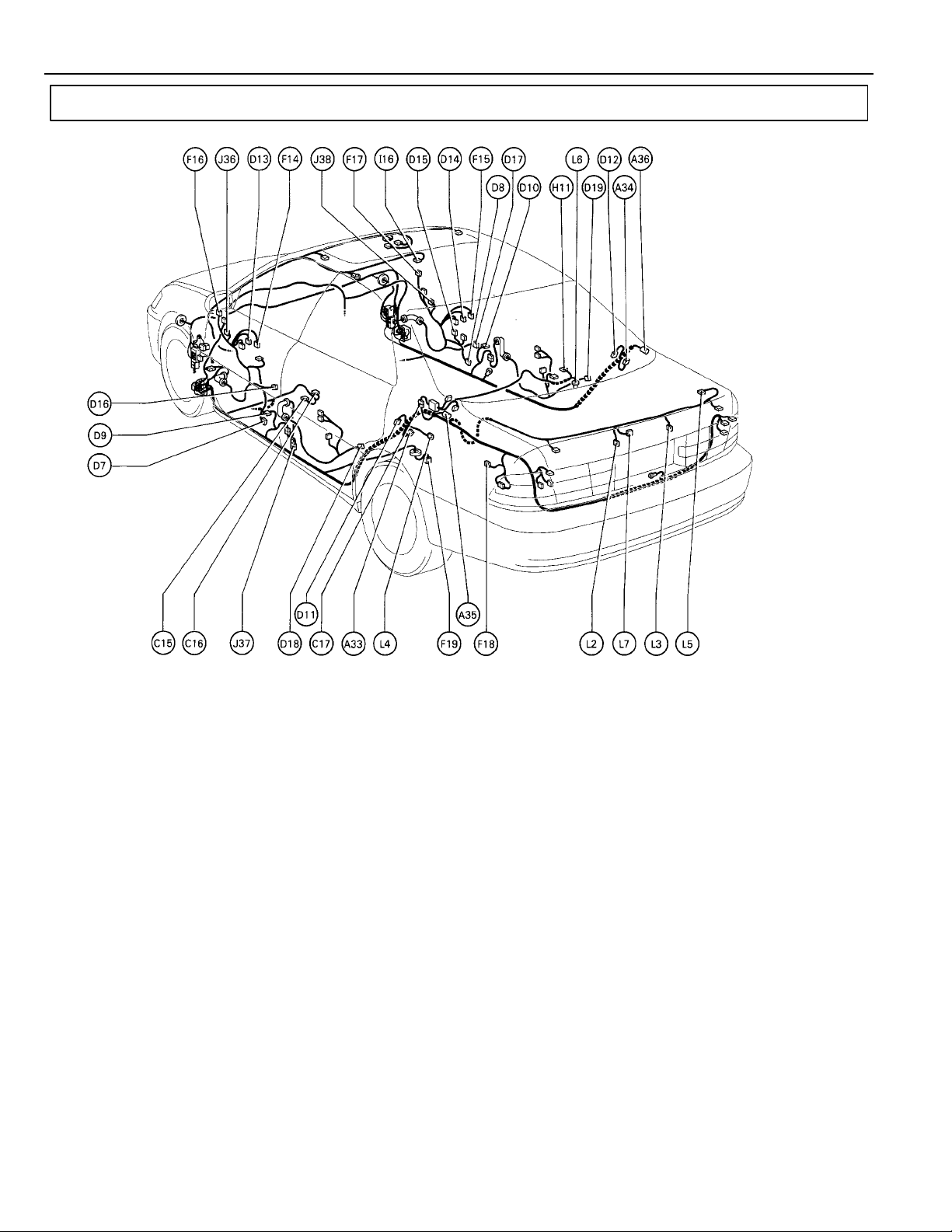
G ELECTRICAL WIRING ROUTING
Position of Parts in Body
A 33 ABS Speed Sensor Rear LH
A 34 ABS Speed Sensor Rear RH
A 35 Absorber Control Actuator Rear LH
A 36 Absorber Control Actuator Rear RH
C 15 Cellular Phone (Hand Set)
C 16 Cellular Phone (Hand Set)
C 17 Choke Coil
D 7 Door Courtesy Light Front LH
D 8 Door Courtesy Light Front RH
D 9 Door Courtesy SW Front LH
D 10 Door Courtesy SW Front RH
D 11 Door Courtesy SW Rear LH
D 12 Door Courtesy SW Rear RH
D 13 Door Key Lock and Unlock SW Front LH
D 14 Door Key Lock and Unlock SW Front RH
D 15 Door Lock Control SW Front RH
D 16 Door Lock Motor and Door Unlock
Detection SW Front LH
D 17 Door Lock Motor and Door Unlock
Detection SW Front RH
D 18 Door Lock Motor and Door Unlock
Detection SW Rear LH
D 19 Door Lock Motor and Door Unlock
Detection SW Rear RH
F 14 Front Door Speaker LH
F 15 Front Door Speaker RH
F 16 Front Tweeter Speaker LH
F 17 Front Tweeter Speaker RH
F 18 Fuel Lid Opener Motor
F 19 Fuel Pump and Fuel Sender
H 11 High Mounted Stop Light
I 16 Interior Light
J 36 Junction Connector
J 37 Junction Connector
J 38 Junction Connector
L 2 License Plate Light LH
L 3 License Plate Light RH
L 4 Light Failure Sensor
L 5 Luggage Compartment Key Unlock SW
L 6 Luggage Compartment Light
L 7 Luggage Compartment Light SW
and Luggage Compartment Door Opener Motor
26
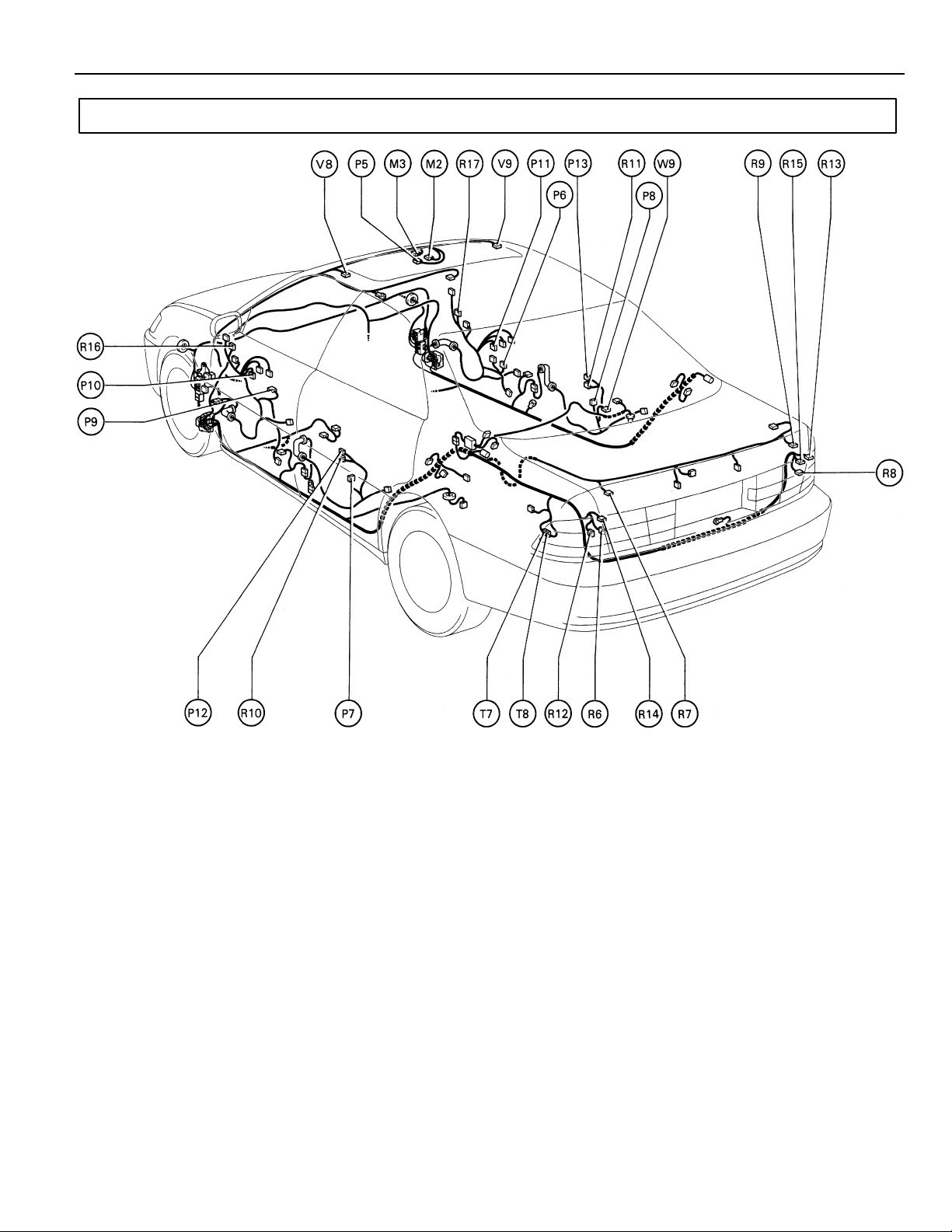
Position of Parts in Body
G
M 2 Moon Roof Control SW and Moon Roof Control Relay
M 3 Moon Roof Moon and Limit SW
P 5 Personal Light
P 5 Personal Light
P 6 Power Window Control SW Front RH
P 7 Power Window Control SW Rear LH
P 8 Power Window Control SW Rear RH
P 9 Power Window Master SW and
Door Lock Control SW Front LH
P 10 Power Window Motor Front LH
P 11 Power Window Motor Front RH
P 12 Power Window Motor Rear LH
P 13 Power Window Motor Rear RH
R 6 Rear Combination Light LH
R 7 Rear Combination Light LH
R 8 Rear Combination Light RH
R 9 Rear Combination Light RH
R 10 Rear Door Speaker LH
R 11 Rear Door Speaker RH
R 12 Rear Side Marker Light LH
R 13 Rear Side Marker Light RH
R 14 Rear Turn Signal Light LH
R 15 Rear Turn Signal Light RH
R 16 Remote Control Mirror and Mirror Heater LH
R 17 Remote Control Mirror and Mirror Heater RH
T 7 Telephone Transceiver and Speaker Relay
T 8 Telephone Transceiver and Speaker Relay
V 8 Vanity Light LH
V 9 Vanity Light RH
W 9 Woofer Speaker
27

G ELECTRICAL WIRING ROUTING
Position of Parts in Seat
B 4 Buckle SW
P 14 Power Seat Control SW
(Driver’s Seat Lumber Support Control)
P 15 Power Seat Control SW
(Driver’s Seat )
P 16 Power Seat Control SW
(Front Passenger’s Seat))
P 17 Power Seat Motor
(Driver’s Seat Front Vertical Control)
P 18 Power Seat Motor
(Driver’s Seat Lumber Support Control)
P 19 Power Seat Motor
(Driver’s Seat Rear Vertical Control)
P 20 Power Seat Motor
(Driver’s Seat Reclining Control)
P 21 Power Seat Motor
(Driver’s Seat Slide Control)
P 22 Power Seat Motor
(Front Passenger’s Seat Front Vertical Control)
P 23 Power Seat Motor
(Front Passenger’s Seat Rear Vertical Control)
P 24 Power Seat Motor
(Front Passenger’s Seat Reclining Control)
P 25 Power Seat Motor
(Front Passenger ’s Seat Slide Control)
P 26 Power Seat Position Sensor
(Driver’s Seat Front Vertical Control)
P 27 Power Seat Position Sensor
(Driver’s Seat Rear Vertical Control)
P 28 Power Seat Position Sensor
(Driver’s Seat Reclining Control)
P 29 Power Seat Position Sensor
(Driver’s Seat Slide Control)
S 11 Seat Heater (Driver ’s Seat)
S 12 Seat Heater (Front Passenger’s Seat)
S 13 Seat Memory SW
S 14 Seat Position Control ECU
S 15 Seat Position Control ECU
26

G ELECTRICAL WIRING ROUTING
: Location of Connector Joining Wire Harness and Wire Harness
: Location of Ground Points
:Location of Splice Points
28

G
CODE JOINING WIRE HARNESS AND WIRE HARNESS (CONNECTOR LOCATION)
EA1
EB1
EB2
EC1
ENGINE ROOM MAIN WIRE AND ENGINE ROOM MAIN NO. 3 WIRE (BEHIND HEADLIGHT LH)
COWL WIRE AND ENGINE ROOM MAIN WIRE (UNDER THE ENGINE ROOM J/B)
ENGINE WIRE AND SENSOR WIRE (LEFT BANK OF THE CYLINDER HEAD)
29

G ELECTRICAL WIRING ROUTING
: Location of Connector Joining Wire Harness and Wire Harness
: Location of Ground Points
30

Connector Joining Wire Harness and Wire Harness
()
G
CODE JOINING WIRE HARNESS AND WIRE HARNESS (CONNECTOR LOCATION)
ID1
ID2
IE1
IE2
IF1
IF2
IF3
IG1
IG2
IH1
FLOOR WIRE AND COWL WIRE (LEFT KICK PANEL)
FRONT DOOR LH WIRE AND INSTRUMENT PANEL WIRE (LEFT KICK PANEL)
FLOOR WIRE AND INSTRUMENT PANEL WIRE (LEFT KICK PANEL)
INSTRUMENT PANEL WIRE AND COWL WIRE (RIGHT SIDE OF INSTRUMENT PANEL J/B)
COWL WIRE AND A/C SUB WIRE (BEHIND RADIO AND PLAYER)
31

G ELECTRICAL WIRING ROUTING
: Location of Connector Joining Wire Harness and Wire Harness
:Location of Splice Points
32

Connector Joining Wire Harness and Wire Harness
()
()
G
CODE JOINING WIRE HARNESS AND WIRE HARNESS (CONNECTOR LOCATION)
II1
IJ1
IK1
IK2
IK3
IL1
IM1
IM2
IM3
IN1
IO1
IO2
IP1
FLOOR NO.3 WIRE AND INSTRUMENT PANEL WIRE (UNDER THE CONSOLE BOX)
INSTRUMENT PANEL WIRE AND COWL WIRE (UNDER THE GLOVE BOX)
EWNGINE WIRE AND COWL WIRE (UNDER THE GLOVE BOX)
ENGINE WIRE AND INSTRUMENT PANEL WIRE (UNDER THE GLOVE BOX)
ENGINE ROOM MAIN WIRE AND COWL WIRE (RIGHT KICK PANEL)
FLOOR NO. 2 WIRE AND COWL WIRE (RIGHT KICK PANEL)
FRONT DOOR RH WIRE AND INSTRUMENT PANEL WIRE (RIGHT KICK PANEL)
FRONT NO. 2 WIRE AND INSTRUMENT PANEL WIRE (RIGHT KICK PANEL)
33

G ELECTRICAL WIRING ROUTING
: Location of Connector Joining Wire Harness and Wire Harness
: Location of Ground Points
:Location of Splice Points
34

Connector Joining Wire Harness and Wire Harness
CODE JOINING WIRE HARNESS AND WIRE HARNESS (CONNECTOR LOCATION)
BQ1
BR1
REAR DOOR LH WIRE AND FLOOR WIRE (LEFT CENTER PILLAR)
REAR DOOR RH WIRE AND FLOOR NO. 2 WIRE (RIGHT CENTER PILLAR)
G
35

G ELECTRICAL WIRING ROUTING
: Location of Connector Joining Wire Harness and Wire Harness
:Location of Splice Point
36

Connector Joining Wire Harness and Wire Harness
CODE JOINING WIRE HARNESS AND WIRE HARNESS (CONNECTOR LOCATION)
BS1
BS2
BT1
FLOOR WIRE AND SEAT NO.1 WIRE (UNDER THE DRIVER’S SEAT)
FLOOR NO.2 WIRE AND SEAT NO. 2 WIRE (UNDER THE FRONT PASSENGER’S SEAT)
’
G
37

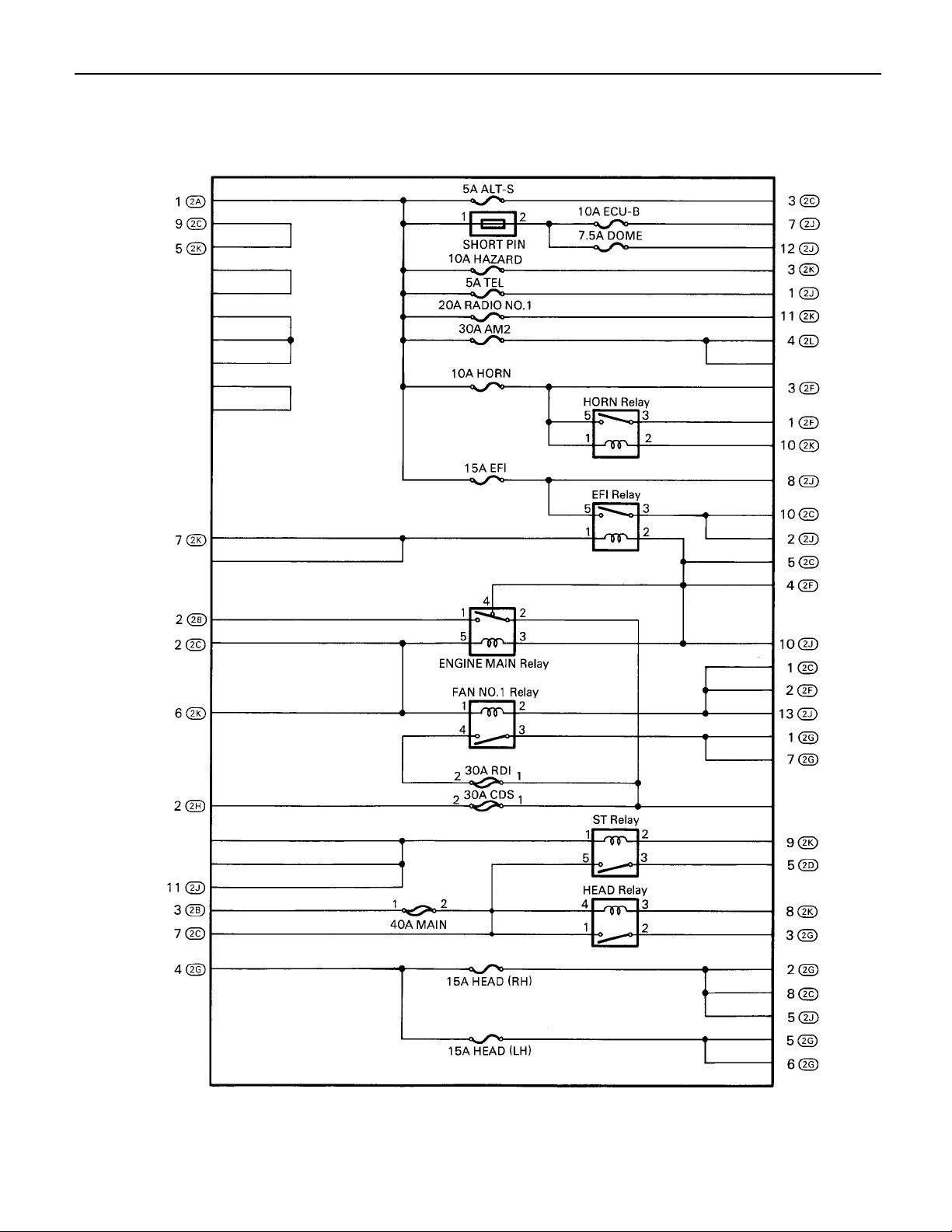
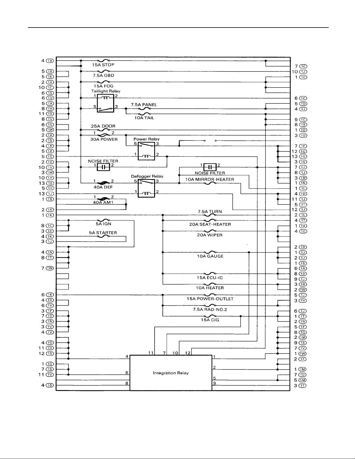
POWER SOURCE
B–G
60A ABS
12
3
ABS SOL RELAY
GR GR–R
R–L
6
3
5
3
1
2
1
4
3
3
3
3
2
3
W–L
W–B
W–R
B–R
E 2
B–R
B–R
D1F1F2E1
100A
ALT
A1C1B1
B–G B–G
FL MAIN 3. 0W
BATTERY
50A
HTR
GR–L
4
L–B L–R
L–W
2
2B
L–B
F, F11
C, F 8
BF 6 , F 7A
EF 9 , F1 0D
FUSIBLE LINK BLOCK
B–R
B
B
1
2A
3
2B
1
1
3
1
HTR RELAY
1
3
ENGINE MAIN RELAY
5A TEL
15A EFI
10A HAZARD
20A RADIO NO. 1
10A HORN
30A AM2
SHORT PIN
12
5A ALT–S
40A MAIN
12
15A HEAD (RH
2
5
4
2
5
)
4
3
ABS MOTOR RELAY
W–B
1
1
L–B
1
30A CDS
12
30A RDI
12
10A ECU–B
7. 5A DOME
HEAD RELAY
1
4
3
5
2C
4
2F
4
2L
7
2C
2
3
3
2G
4
2G
GR–R
3
B–R
W–B
W–B
W–R
W–B
W–B
W–B
R–G
(*1)
R–B
(*1)
)
R–B
USA
(
R
(*1)
56
15A HEAD (LH
)
EC

* 1 : CANADA
B–R
W–R
R–G
(*1)
R–B
(*1)
R
(*1)
2
AM1
7
AM2
I13
IGNITION SW
R–G
B–R
I 1
B–R
W
L–R
3
ACC
B–Y
4
IG1
B–R
6
IG2
R
8
ST2
W–R
DRL NO. 2 RELAY
13
2
R–L
TAILLIGHT RELAY
5
1
POWER RELAY
5
1
DEFO G GER RELAY
5
1
2
R–B
2
3
2
3
2
3
2
5A DRL NO. 2
12
10A H–LP RH (LWR
12
10A H–LP LH (LWR
12
10A TAIL
7. 5A PANEL
1
NOISE FILTER
10A MIRROR–HEATER
2
R–L
2
)
2
)
2
W–R
W–R
R–G
R
7
W–B
1J
12
Y–G
1J
J15
JUNCTION
CONNECTOR
W–B
A
II
4
1B
1
1B
2
1K
6
1K
1
1K
3
1K
4
1K
5
1K
5
1B
2
4
15A FOG
25A DOOR
15A STOP
7. 5A ODB
30A POWER
12
NOISE FILTER
1
12
12
R
2
2
2
2
40A DEF
40A AM1
15A CIG
7. 5A RAD–NO. 2
15A POWER–OUTLET
20A SEAT–HEATER
15A ECU–IG
10A HEATER
10A GAUGE
20A WIPER
7. 5A T URN
5A IGN
5A STARTER
57

POWER SOURCE
24
COWL WIRE AND INSTRUMENT PANEL J/B (LOWER FINISH PANEL)
20
ENGINE ROOM MAIN WIRE AND ENGINE ROOM J/B (ENGINE COMPARTMENT LEFT)
SERVICE HINTS
T AILIGHT RELAY
5–3:CLOSED WITH THE LIGHT CONTROL SW AT TAIL OR HEAD POSITION
HEAD RELAY(USA)
1–2:CLOSED WITH THE LIGHT CONTROL SW AT HEAD POSITION OR THE DIMMER SW A T FLASH POSITION
HEAD RELAY(CANADA)
1–2:CLOSED WITH THE LIGHT CONTROL SW AT HEAD POSITION OR THE DIMMER SW A T FLASH POSITION
CLOSED WITH THE ENGINE RUNNING AND THE PARKING BRAKE PEDAL RELEASED (PARKING BRAKE SW OFF)
I13 IGNITION SW
2–3:CLOSED WITH THE IGNITION KEY AT ACC OR ON POSITION
2–4:CLOSED WITH THE IGNITION KEY AT ON OR ST. POSITION
7–6:CLOSED WITH THE IGNITION KEY AT ON OR ST POSITION
7–8:CLOSED WITH THE IGNITION KEY AT ST POSITION
: PARTS LOCA TION
CODE SEE PAGE CODE SEE PAGE CODE SEE PAGE
F 6 A
F 7 B
F 8 C
26
26
26
: RELAY BLOCKS
CODE SEE PAGE RELA Y BLOCKS (RELAY BLOCK LOCATION)
1
22
2
23
3
23
ENGINE ROOM R/B (ENGINE COMPAR TMENT LEFT)
ENGINE ROOM NO.2 R/B (ENGINE COMPAR TMENT LEFT)
ENGINE ROOM NO.3 R/B (RADIATION UPPER SUPPORT RH)
F 9 D
F10 E
F11 F
26
26
26
I13
J15
28
29
: JUNCTION BLOCK AND WIRE HARNESS CONNECTOR
CODE SEE PAGE JUNCTION BLOCK AND WIRE HARNESS (CONNECTOR LOCATION)
1B
1J
1K
2A
2B
2C
2F
2G
2L
24
20
20
COWL WIRE AND INSTRUMENT PANEL J/B (LOWER FINISH PANEL)
ENGINE ROOM MAIN WIRE AND ENGINE ROOM J/B (ENGINE COMPAR TMENT LEFT)
COWL WIRE AND ENGINE ROOM J/B (ENGINE COMPAR TMENT LEFT)
: GROUND POINTS
CODE SEE PAGE GROUND POINTS LOCATION
EC
II
34
36
LEFT RADIATION SIDE SUPPORT
INSTRUMENT PANEL BRACE LH
: SPLICE POINTS
CODE SEE PAGE WIRE HARNESS WITH SPLICE POINTS CODE SEE PAGE WIRE HARNESS WITH SPLICE POINTS
E 2
34
AF 6 BF 7 CF 8 DF 9 EF10
COWL WIRE
11111
I 1
38 COWL WIRE
FF11 I13 J15
AA
12
58
X234
X678
AAAA
(
HINT : SEE PAGE 7
)

MEMO
59

STARTING AND IGNITION
ACC
AM1
76
AM2
W–R
1K5
1B5
I13
IGNITION SW
IG1
IG2
ST2
8
B–R
R
B–R
R
5A
STARTE
1K4
R
1J3
R
W–
2L4
2A1
B
C1
A1
B–G
30A
AM2
F 6 , F 8
FUSIBLE LINK
BLOCK
FL MAIN
3. 0W
BATTERY
B–W
IK211
6
IK210
GR GR
BC
ABAB
B–WB–W
B
BB–W
B
5
P 1P
PARK/NEUTRAL
POSITION SW
JUNCTION
CONNECTOR
BJ 8 , J 9A
8
IK2
GRGR
2
40A
MAIN
1
2B3
B
C
A
B–R
1
A
STARTER
ST
RELAY
51
32
2D52K92J11
–B
W
IG21
B–R
W–B
1
B
M
BS 1 , S 2A
GR
W–B
T 3
THEFT DETE RR ENT
ECU
9
SRLY
J26
JUNCTION
CONNECTOR
N
60

B–R
1K3
1C8
B–R
IK312
RL
B–
A
J22
JUNCTION CONNECTOR
A
A
B–R
1
B–W
2
IGNITION COIL NO. 3
I 5
21109
IGC3 IGC2 IGC1 +B
IGFIGT3IGT2IGT1 GND
–R
W
14 12 15 1 6 24
NSW
IGF
STA
13
A
B–R
1
2
IGNITION COIL NO. 2
I 4
Y
I 2
IGNITER
G–B
L
IGT3
E10
ENGINE CONTROL
MODULE
A
B–R
1
2
IGNITION COIL NO. 1
I 3
G
R–Y
B
IGT2
GR
IGT1
A
N 1
NOISE FILTER
B–R
1
)
2
IGNITION
(
B–R
37654
BR
GR
BR
EE
61

STARTING AND INGNITION
()
()
SERVICE HINTS
I13 IGNITION SW
7–8 :CLOSED WITH THE IGNITION SW AT ST POSITION
7–6 :CLOSED WITH THE IGNITION SW AT ON OR ST POSITION
S 1 A , S 2 B STARTER
POINTS CLOSED WITH THE PARK/NEUTRAL POSITION SW IN P OR N POSITION AND THE IGNITION SW AT ST POSITION
P1 P ARK/NEUTRAL POSITION SW
5–6 :CLOSED WITH THE A/T SHIFT LEVER IN P OR N POSITION
: PARTS LOCA TION
CODE SEE PAGE CODE SEE PAGE CODE SEE PAGE
E10
F 6 A
F 8 C
I 2
I 3
I 4
28
26
26
27
27
27
: JUNCTION BLOCK AND WIRE HARNESS CONNECTOR
CODE SEE PAGE JUNCTION BLOCK AND WIRE HARNESS (CONNECTOR LOCATION)
1B
1C
2D
1J
1K
2A
2B
2J
2K
2L
24
20
20
COWL WIRE AND INSTRUMENT PANEL J/B (LOWER FINISH PANEL)
ENGINE ROOM MAIN WIRE AND ENGINE ROOM J/B (ENGINE COMPAR TMENT LEFT)
COWL WIRE AND ENIGNE ROOM J/B (ENGINE COMPAR TMENT LEFT)
I 5
I13
J 8 A
J 9 B
J22
J26
27
28
29
29
29
29
N 1
P 1
S 1 A
S 2 B
T 3
27
27
27
27
29
: CONNECTOR JOINING WIRE HARNESS AND WIRE HARNESS
CODE SEE PAGE JOINING WIRE HARNESS AND WIRE HARNESS (CONNECTOR LOCATION)
IG2 36
IK2
IK3
38 ENGINE WIRE AND COWL WIRE (UNDER THE GLOVE BOX)
INSTRUMENT PANEL WIRE AND COWL WIRE (RIGHT SIDE OF INSTRUMENT PANEL J/B)
: GROUND POINTS
CODE SEE PAGE GROUND POINTS LOCATION
EE 34
REAR SIDE OF SURGE TANK
62

E10 BLACKI 2
AF 6 CF 8
XX
12 14 15 16
13
XXX 24XX
X
XXX
BLACKI 3 BLACKI 4 BLACKI 5
12 12 12
B
GRAY
J 9
CCC
(
HINT : SEE PAGE 7
X
56
AAA AA
AAAAAAAA
(
HINT : SEE PAGE 7
)
GRAYP 1
ORANG E
J22 J26
)
AS 1 B BLACKS 2
11
12345 109X76
I13
X
X67 8
N 1
BBB
(
HINT : SEE PAGE 7
B
)
12
ORANG ET 3
1
1
X9
GRAY
AJ 8
GRAY
BBB
(
HINT : SEE PAGE 7
)
63

CHARGING
B–G
ACC
2
WB–Y
AM1
IG1
4
* 1 : USA
* 2 : CANADA
CF 6 , F 8AD, F 9 F, F11
WB–R
1K21K5
2
1
1B1
B–G
E 2
B–R
D1F1F2
100A
ALT
A1C1
7
I13
W–R
IGNITION SW
40A AM1
B–R
1B5
W–R
2L42C3
30A AM 2
2A1
B
IG2
ST2
W
6AM2
B–R
1K3
5A IGN
1T8
R
B–
B2
BC 7 , C 8A
A10
CHARGE WARNING LIGHT
[COMB. METER]
Y
5A ALT–S
IG24
)
Y
*2
(
ABAB
)
Y
*1
(
BB
)
Y
*2
(
)
MAIN
(
TO DAYTIME RUNNING
LIGHT RELAY
)
Y
*2
(
B–Y
1K1
10A GAUGE
1J2
R–L
IM24
BJ18 , J19A
R–L
JUNCTION
CONNECTOR
64
BATTERY
B
BG 1 , G 2A
GENERATOR
EB26
Y
W
B3B1B2A1
SLIG B
IC REGULATOR
R–L
B–G
FUSIBLE LINK BLOCK
B–G
FL MAIN
3. 0W

SERVICE HINTS
24
()
G 2 B GENERATOR
B 3–GROUND : 13.9–15.1 VOLTS WITH THE ENGINE RUNNING AT 2000 RPM AND 25C (77F)
13.5–14.3 VOLTS WITH THE ENGINE RUNNING AT 2000 RPM AND 115C (239F)
B 2–GROUND : 0–4 VOL TS WITH THE IGNITION SW AT ON POSITION AND ENGINE NOT RUNNING
: PARTS LOCA TION
CODE SEE PAGE CODE SEE PAGE CODE SEE PAGE
C 7 A
C 8 B
F 6 A
F 8 C
28
28
26
26
F 9 D
F11 F
G 1 A
G 2 B
26
26
26
26
I13
J18 A
J19 B
28
29
29
: JUNCTION BLOCK AND WIRE HARNESS CONNECTOR
CODE SEE PAGE JUNCTION BLOCK AND WIRE HARNESS (CONNECTOR LOCATION)
1B
1J
1K
1T
2A
2C
2L
24
24
20
20
COWL WIRE AND INSTRUMENT PANEL J/B (LOWER FINISH PANEL)
INSTRUMENT PANEL WIRE AND INSTRUMENT PANEL J/B (LOWER FINISH PANEL)
ENGINE ROOM MAIN WIRE AND ENGINE ROOM J/B (ENGINE COMPAR TMENT LEFT)
COWL WIRE AND ENGINE ROOM J/B (ENGINE COMPAR TMENT LEFT)
: CONNECTOR JOINING WIRE HARNESS AND WIRE HARNESS
CODE SEE PAGE JOINING WIRE HARNESS AND WIRE HARNESS (CONNECTOR LOCATION)
EB2
IG2
34
36
COWL WIRE AND ENGINE ROOM MAIN WIRE (UNDER THE ENGINE ROOM J/B)
INSTRUMENT PANEL WIRE AND COWL WIRE (RIGHT SIDE OF INSTRUMENT PANEL J/B)
IN2 38 ENGINE ROOM MAIN WIRE AND COWL WIRE (RIGHT KICK PANEL)
: SPLICE POINTS
CODE SEE PAGE WIRE HARNESS WITH SPLICE POINTS CODE SEE PAGE WIRE HARNESS WITH SPLICE POINTS
E 2
34
COWL WIRE
ABLUEC 7 BC 8 AF 6
XXX10XX 2XX
DF 9
1
1
12
1
1
B BLACKG 2AG 1FF11CF 8
123
I13
X2 4
X67
ABLACKJ1 8 B BLAC KJ19
BB
(
HINT : SEE PAGE 7
)
BB
(
HINT : SEE PAGE 7
65
)

ENGINE CONTROL
SYSTEM OUTLINE
THIS SYSTEM UTILIZES AN ENGINE CONTROL MODULE AND MAINTAINS OVERALL CONTROL OF THE ENGINE,
TRANSMISSION AND SO ON. AN OUTLINE OF THE ENGINE CONTROL IS EXPLAINED HERE.
1. INPUT SIGNALS
( 1) ENGINE COOLANT TEMP. SIGNAL CIRCUIT
THE ENGINE COOLANT TEMP. SENSOR DETECTS THE ENGINE COOLANT TEMP. AND HAS A BUILT–IN
THERMISTOR WITH A RESISTANCE WHICH VARIES ACCORDING TO THE WATER TEMP. IS INPUT INTO
TERMINAL THW OF THE ENGINE CONTROL MODULE AS A CONTROL SIGNAL.
( 2) INTAKE AIR TEMP. SIGNAL CIRCUIT
THE INTAKE AIR TEMP. SENSOR IS INSTALLED IN THE MASS AIR FLOW METER AND DETECTS THE INTAKE AIR
TEMP., WHICH IS INPUT AS A CONTROL SIGNAL INTO TERMINAL THA OF THE ENGINE CONTROL MODULE.
( 3) OXYGEN SENSOR SIGNAL SYSTEM
THE OXYGEN DENSITY IN THE EXHAUST GASES IS DETECTED AND INPUT AS A CONTROL SIGNAL INTO
TERMINALS OXL1, OXR1 AND OXS OF THE ENGINE CONTROL MODULE TO MAINTAIN STABLE DETECTION
PERFORMANCE BY THE HEATED OXYGEN SENSOR, A HEATER IS USED FOR WARMING THE SENSOR. THE
HEATER IS ALSO CONTROLLED BY THE ENGINE CONTROL MODULE (HTL, HTR AND HTS).
( 4) RPM SIGNAL SYSTEM
CAMSHAFT POSITION AND CRANKSHAFT POSITION ARE DETECTED BY THE CAMSHAFT POSITION SENSOR AND
CRANKSH AFT POSITION SENSOR. THE CAMSHAFT POSITION IS INPUT AS A CONTROL SIGNAL TO TERMINAL
G22+ OF THE ENGINE CONTROL MODULE, AND THE ENGINE RPM IS INPUT INTO TERMINAL NE+.
( 5) THROTTLE SIGNAL CIRCUIT
THE THROTTLE POSITION SENSOR DETECTS THE THROTTLE VALVE OPENING ANGLE AS A CONTROL SIGNAL,
WHICH IS INPUT INTO TERMINAL VTA1 OF THE ENGINE CONTROL MODULE.
( 6) VEHICLE SPEED SIGNAL SYSTEM
THE VEHICLE SPEED SENSOR, INSTALLED INSIDE THE TRANSMISSION, DETECTS THE VEHICLE SPEED AND
INPUTS A CONTROL SIGNAL INTO TERMINAL SPD OF THE ENGINE CONTROL MODULE.
( 7) PARK/NEUTRAL POSITION SW SIGNAL SYSTEM
THE PARK/NEUTRAL POSITION SW DETECTS WHETHER THE SHIFT POSITION IS IN NEUTRAL, PARKING OR
NOT, AND INPUTS A CONTROL SIGNAL INTO TERMINAL STA OF THE ENGINE CONTROL MODULE
( 8) A/C SW SIGNAL SYSTEM
THE A/C CONTROL ASSEMBLY INPUTS THE A/C OPERATIONS INTO TERMINAL A/C OF THE ENGINE CONTROL
MODULE AS A CONTROL SIGNAL.
( 9) BATTERY SIGNAL CIRCUIT
VOLTAGE IS CONSTANTLY APPLIED TO TERMINAL BATT OF THE ENGINE CONTROL MODULE. WHEN THE
IGNITION SW IS TURNED ON, VOLTAGE FOR THE ENGINE CONTROL MODULE OPERATION IS APPLIED TO
TERMINAL +B OF THE ENGINE CONTROL MODULE VIA THE EFI RELAY.
(10) INTAKE AIR VOLUME SIGNAL CIRCUIT
INTAKE AIR VOLUME IS DETECTED BY THE MASS AIR FLOW METER AND A SIGNAL IS INPUT INTO TERMINAL
VG OF THE ENGINE CONTROL MODULE AS A CONTROL SIGNAL.
(11) NSW SIGNAL CIRCUIT
TO CONFIRM WHETHER THE ENGINE IS CRANKING, THE VOLTAGE APPLIED TO THE STARTER MOTOR DURING
CRANKING IS DETECTED AND THE SIGNAL IS INPUT INTO TERMINAL NSW OF THE ENGINE CONTROL MODULE
AS A CONTROL SIGNAL.
(12) ENGINE KNOCK SIGNAL CIRCUIT
ENGINE KNOCKING IS DETECTED BY THE KNOCK SENSOR 1 AND 2, THEN THE SIGNALS ARE INPUT INTO
TERMINALS KNKR AND KNKL OF THE ENGINE CONTROL MODULE AS A CONTROL SIGNAL.
66

2. CONTROL SYSTEM
SFI (SEQUENTIAL MULTIPORT FUEL INJECTION) SYSTEM
THE SFI SYSTEM MONITORS THE ENGINE CONDITION THROUGH THE SIGNALS, WHICH ARE INPUT FROM EACH
SENSOR (INPUT SIGNALS (1) TO (12)). THE BEST FUEL INJECTION VOLUME IS DECIDED BASED ON THIS DATA
AND
THE PROGRAM MEMORIZED BY THE ENGINE CONTROL MODULE, AND THE CONTROL SIGNAL IS OUTPUT TO
TERMINALS #10, #20, #30, #40, #50, AND #60 OF THE ENGINE CONTROL MODULE TO OPERATE THE INJECTOR
(INJECT THE FUEL). THE SFI SYSTEM PRODUCES CONTROL OF FUEL INJECTION OPERATION BY THE ENGINE
CONTROL MODULE IN RESPONSE TO THE DRIVING CONDITIONS.
ESA (ELECTRONIC SPARK ADVANCE) SYSTEM
THE ESA SYSTEM MONITORS THE ENGINE CONDITION THROUGH THE SIGNALS, WHICH ARE INPUT TO THE
ENGINE CONTROL MODULE FROM EACH SENSOR (INPUT SIGNALS FROM 1, 3, 4, 12). THE BEST IGNITION TIMING
IS DECIDED ACCORDING TO THIS DATA AND THE MEMORIZED DATA IN THE ENGINE CONTROL MODULE AND
THE CONTROL SIGNAL IS OUTPUT TO TERMINALS IGT1, IGT2 AND IGT3. THIS SIGNAL CONTROLS THE IGNITER
TO PROVIDE THE BEST IGNITION TIMING FOR THE DRIVING CONDITIONS.
HEATED OXYGEN SENSOR HEATER CONTROL SYSTEM
THE HEATED OXYGEN SENSOR HEATER CONTROL SYSTEM TURNS THE HEATER ON WHEN THE INTAKE AIR
VOLUME IS LOW (TEMP. OF EXHAUST EMISSIONS IS LOW), AND WARMS UP THE HEATED OXYGEN SENSOR TO
IMPROVE DETECTION PERFORMANCE OF THE SENSOR. THE ENGINE CONTROL MODULE EVALUATES THE
SIGNALS FROM EACH SENSOR (INPUT SIGNALS FROM 1, 4, 9, 10), CURRENT IS OUTPUT TO TERMINALS HTL,
HTR AND HTS, CONTROLLING THE HEATER.
IDLE AIR CONTROL SYSTEM
THE IDLE AIR CONTROL SYSTEM (ROTARY SOLENOID TYPE) INCREASES THE RPM AND PROVIDES IDLE STABILITY
FOR FAST IDLE–UP WHEN THE ENGINE IS COLD, AND WHEN THE IDLE SPEED HAS DROPPED DUE TO ELECTRICAL
LOAD AND SO ON, THE ENGINE CONTROL MODULE EVALUATES THE SIGNALS FROM EACH SENSOR (INPUT
SIGNALS FROM 1, 4, 5, 8, 9), CURRENT IS OUTPUT TO TERMINALS RSO AND RSC TO CONTROL IDLE AIR CONTROL
VALVE.
EGR CONTROL SYSTEM
THE EGR CONTROL SYSTEM DETECTS THE SIGNAL FROM EACH SENSOR (INPUT SIGNALS FROM 1, 4, 9, 10),
AND OUTPUTS CURRENT TO TERMINAL EGR TO CONTROL THE VSV (EGR).
THE EGR VALVE POSITION SENSOR IS MOUNTED ON THE EGR VALVE. THIS SENSOR CONVERTS THE EGR VALVE
OPENING HEIGHT INTO A VOLTAGE AND SENDS IT TO THE ENGINE CONTROL MODULE AS THE EGR VALVE
POSITION SIGNAL.
ACIS (ACOUSTIC CONTROL INDUCTION SYSTEM)
ACIS INCLUDES A VALVE IN THE BULKHEAD SEPARATING THE SURGE TANK INTO TWO PARTS. THIS VALVE IS
OPENED AND CLOSED IN ACCORDANCE WITH THE DRIVING CONDITIONS TO CONTROL THE INTAKE MANIFOLD
LENGTH IN TWO STAGES FOR INCREASED ENGINE OUTPUT IN ALL RANGES FROM LOW TO HIGH SPEEDS.
THE ENGINE CONTROL MODULE JUDGES THE ENGINE SPEED BY THE SIGNALS ((4), (5)) FROM EACH SENSOR
AND OUTPUTS SIGNALS TO THE TERMINAL ACIS TO CONTROL THE VSV (INTAKE AIR CONTROL).
3. DIAGNOSIS SYSTEM
WITH THE DIAGNOSIS SYSTEM, WHEN THERE IS A MALFUNCTION IN THE ENGINE CONTROL MODULE SIGNAL
SYSTEM, THE MALFUNCTIONING SYSTEM IS RECORDED IN THE MEMORY.
4. FAIL–SAFE SYSTEM
WHEN A MALFUNCTION OCCURS IN ANY SYSTEMS, IF THERE IS A POSSIBILITY OF ENGINE TROUBLE BEING
CAUSED BY CONTINUED CONTROL BASED ON THE SIGNALS FROM THAT SYSTEM, THE FAIL–SAFE SYSTEM
EITHER CONTROLS THE SYSTEM BY USING DATA (STANDARD VALUES) RECORDED IN THE ENGINE CONTROL
MODULE MEMORY OR ELSE STOPS THE ENGINE.
67

ENGINE CONTROL
R
B–R
76
W–R
1K5
1B5
2L4
2A1
BW
C1
A1
AM2 IG2
ST2
I13
IGNITION SW CIR OPN
30A
AM2
J22
JUNCTION CONNE CTOR
AAAAAAAAAA
B–R
B–R
A
FUS IBL E LINK
BLOCKCF 6 , F 8
B–R
8
R
B–R
B–R
B–R
2
1
INJECTOR NO. 1
I 6
B–R
2
1
INJECTOR NO. 2
I 7
B–R
1W71K3
1C8
B–R
IK312
B–R
A
B–R
2
1
INJECTOR NO. 3
I 8
B–R
11
15
RELAY
5A
IGN
B–R
2
1
INJECTOR NO. 4
I 9
B–R
2
1
INJECTOR NO. 5
I10
B–R
2
1
INJECTOR NO. 6
I11
23
11
G–R
EB25
G–R G–R
F19
FUEL
PUMP
L–BL–BL–BW–B
EB24
ID17IK23
4
M
5
B–R
68
B–G –R
FL MAIN
3. 0W
BA
TTERY
L
R
Y
W
R–L
G
G–R
G
R–L
W
Y
R
L
B–R
B–R
B–R
B–R
J37
JUNCTION
CONNECTOR
A
BN

FROM POWER SOURCE SYSTEM (SEE PAGE 56
B–R
B–YR
)
B–Y
B–Y
B–R
2K7
15
23
2F42C10 2J22J8
2C5
B–R
W–B
W–B
BJ28 , J29A
15A
EFI
B–YB–Y
B–Y
B–Y
IK39
O. 1
FRO M F AN N
RELAY
IK21
G–W G–W
B9
CF
EFI
RELAY
B–YB–Y
B–Y
ABAB
B–Y
BBBB
UNCTION CONNECT
JOR
A23 A14 D13
+B BATT STA
1K4
5A
STARTER
1J3
B–W
B
B
ONNECTOR
UNCTION
26
B
JCJ
B–W
P 1
IK211
B–W
J 8 , J 9A
JUNCTION
CONNECTOR
8
IK2
GR
ENGINE CONTROL M ODULE
B–W
5
P
N
PARK/NEUTRAL
POSITION SW
B
GR
BE 7 , E 8AC, E 9 D, E10
6
IK210
GR GR
BC
AB
B–W
D14
NSW
G–R
G
R–L
W
Y
R
L
B–R
B–R
B–R
B–R
FC #60#50#40#30#20#10
C18 D5D6D7D8D9D10
G
R–L
W–B
EC
Y
W
R
NEO
EFI+
EFI–
TRC+
A19
A26
A25
L
BR–W
B
W
FROM TRACTION
CONTROL ECU
TRC–
A28
A27
L
G
B–R
B–R
B–R
B–R
B–Y
69

ENGINE CONTROL
B–Y
B–Y
B–Y
FROM POWER SOURCE SYSTEM (SEE PAGE 56
J23
A
A
)
JUNCTION CONNECTOR
AAAA
B–Y
10A
TAIL
10A
MIRROR–
HEATER
1C9
G–OG–O
AA
BJ18 , J1 9A
BC
JUNCTION CONNECTO R
1J11
B–Y
15A
STOP
1C7
2
STOP LIGHT SW
S10
1
WW
G–
1R4
1R5
A
A
G–W
JUNCTION CONNECTOR
J27
G–W
A24
)
NTAKE AIR CONTRO
IL
(
VSV
V 6
B–Y
1
)
EVAP
(
VSV
V 5
2
LG
B2B12B8B6A2A3
EVP1EGRTPCACISSTPELS2ELS
V 4
)
EGR
(
VSV
B–Y
1
2
Y–G
B–Y
1
2
R–Y
B–Y
)
1
2
APOR PRESSURE S
VENSOR
(
VSV
V 7
W–R
70
E 7 , E 8
AC
ENGINE CONTROL MODULE
222
IGNITION COIL NO. 1
I 3
B–R
B–R
B–R
B–R
B–Y
B
IGNITION COIL NO. 2
I 4
, E 9D, E10
IGNITION COIL NO. 3
I 5
111
G
Y
L
21107 6 54
+B GND
I 2
IGNITER
B–R
GR
BR–Y
E2GTHAVGIGFIGT3IGT2IGT1
B7C8C21D12D15D16D24
W–R
LG–B
IGFIGT3IGT2IGT1IGC1IGC2IGC3
BR
EE
P
513
M 1
MASS AIR FLOW METER
B–Y
L–Y
2439
R–B
BR

J23
JUNCTION CONNECTOR
AAA
B–Y
A
B–Y
(
SHIELDED
BR
BR
BR
)
B–Y
B–Y
2
LE AIR CONTROL VALVE
1
ID
I
RSO RSC HTS OXS HTR OXR1 HTL OXL1 TC
31
R–W
D23 D22 A17 A18 B11 C13 B10 C19 B5
Y–B
)
ATED OXYGEN SEN
HE SOR
(
H10
+B E1
HT OX
NK 1 SENSOR 2
BA
P–B
)
SHIELDED
(
IK12
BR BR
42
31
H 5
B
ENGINE CONTROL MODULE
B–Y
)
+B E1
HT OX
D OXYGEN SEN
1 SENSOR 1
BANK
HEATE SOR
(
L–B
BR
42
)
W
SHIELDED
(
BE 7 , E 8AC, E 9 D, E10
)
SHIELDED
(
BR
42
3131
B
B–Y
)
R1
H 6
HEATED OXYGEN SENSOR
+B E1
HT OX
BANK 2 SENSO
(
Y–R
BR
I 5 I 5
BR
B–Y
TE1
8
BR
BR
BR
BR
312
E1+B
DATA LINK
CONNECTOR 1
D 1
L–W
E2 VTA1 VC THG THW PTNK EGLS PS
C22 C7C1B14 C20 B13 B15 D31
L–R
23
PTNK
VCC E2
RESSURE SEN
31 21
POR P SO
VA R
Y
I 5
BR
I 6
E 2
Y
W–G
E POSITION S
VALV ENS
EGR OR
BR
Y
L
BRBR
I 5 I 5
231
E2 VTA VC
T 2
THROTTLE POSITION SENSOR
BR
E 4
G–B
2
1
BR
ENGINE COOLANT TEMP. SENSOR
V 1
BR
Y
G–Y
E 1
2
1
EGR GAS TEMP. SENSOR
BR
Y
I 5
BR
Y
P 2
B–L
1
POWER STEERING
OIL PRESSURE SW
71

ENGINE CONTROL
BR
BR
BR
)
SHIELDED
BR
BR
BR
C 2 C 1
CRANKSHAFT
POSITION SENSOR
)
B–R
SHIELDED
(
BR
BR
(
SHIELDED
A
J24
JUNCTION
CONNECT OR
V–W
BR
)(
BR
W
G–R
BR
BR
BR
BR
BR
BR
BR
BR
I 6
CAMSHAFT POSITION
SENSOR
LL
(
SHIELDED
I 6
1221
B–W
)
BR
BR
W
BR
BR
I 5
A
A
A
A
A
A
A
A
A
C5C6C17 B16 D1A8B3A12
W
W
BE 7 , E 8AC, E 9 D, E10
THWO
I 6
)
SHIELDED
(
TW2
A9
BR
V
B14
B–Y
LG–B
B10 B13 A16
B–O
AFAF
BD
B–O
IGNAC1ACT
B–O
BJ28 , J29A
BR
BD
JUNCTIO N CONNECTOR
B–O
ENGINE CONTROL MODULE
KNKL KNKR ACT A/C TACH E01 E02 E03
)
)(
)(
SHIELDED
(
EC14EC12EC11EC13
)
SHIELDED
(
W
SHIELDED
SHIELDED
(
(
)
)
W
SHIELDED
SHIELDED
11
BR
SPDWSILADJ2E1G22+NE–NE+
D33 D28D34A13A16A5C15C14
BR
BR BR BR
B–O
72
K 2
TO ABSORBER
KNOCK SENSOR 2
K 1
KNOCK SENSOR 1
A/C CONTROL ASSEMBLY
BA1 4 , A1 5A
CONTROL ECU
ED

FROM POWER SOURCE SYSTEM (SEE PAGE 56
)
BR
(
SHIELDED
BR
W
G–R
V–W
MALFUNCTION
10A
GAUGE
1D2
R–LR–L
D
J 4
JUNCTION
CONNECTOR
D
CC 7 , C 9A
D, C10
D3C10
)
SPEEDOMETER
L
IL17IL12
L
PP
23
SESI
INDICATOR LAMP
G–R
G–R
7. 5A
OBD
)
1J10 1J1
6
IK3
BR
)
SHIELDED
(
BJ 8 , J 9A
DATA LIN K
CONNECTOR 3
D 4
C
J17
JUNCTI ON
CONNECTOR
JUNCTION
CONNECTOR
I11
BB
B
AC
BR BR
JUNCTION CONNECTOR
165
BATSG
CGSIL
74
CV–W
V–W
BA
BJ 8 , J 9A
AA
W–BW–B W–B
1J8
AD
BF
R–LR–L
IK22
A
A
JUNCTION
CONNECTOR
V–W
J25
JUNCTION
CONNECTOR
R–L
BJ28 , J2 9A
3
IJ1
COMBINATION METER
TACHOMETER
A13 D5D13D4C9
B–O
IJ16IJ110
B–O
B–O
1J7
BR
A
J15
JUNCTION
CONNECTOR
IIEE
R–L
IK13
IG+
COMBINATION METER
V 2
VEHICLE SPEED SENSOR
G–R
(
1
R–L
BR
IJ
73

ENGINE CONTROL
SERVICE HINTS
CIR OPN RELAY
1 5 – 1 3 : CLOSED WITH THE STARTER RUNNING
EFI RELAY
5–3 : CLOSED WITH THE IGNITION SW AT ON OR ST POSITION
E 4 ENGINE COOLANT TEMP. SENSOR
1–2 : 10.0 –20.0 KΩ (–20C, –4F)
4.0 –07.0 KΩ (000C, 32F)
2.0 –03.0 KΩ (020C, 68F)
0.9 –01.3 KΩ (–40C, 104F)
0.4 –00.7 KΩ (–60C, 140F)
0.2 –00.4 KΩ (–80C, 176F)
E7 A , E 8 B , E 9 C , E10 D ENGINE CONTROL MODULE
VOLTAGE AT ENGINE CONTROL MODULE WIRING CONNECTOR
BATT–E1 : ALWAYS 9.0–14.0 VOLTS
+B–E1 : 9.0–14.0 VOLTS (IGNITION SW TO ON POSITION)
VC–E2 : ALWAYS 4.5–5.5 VOLTS (IGNITION SW A T ON POSITION)
VTA1–E2: 0.3–0.8 VOLTS (IGNITION SW ON AND THROTTLE VALVE FULLY CLOSED)
VG–E2G : 1.1–1.5 VOLTS (ENGINE IDLING AND A/C SW OFF)
THA–E2 : 0.5–3.4 VOLTS (ENGINE IDLING AND INTAKE AIR TEMP. 20C, 68F)
THW–E2 : 0.2–1.0 VOL TS (ENGINE IDLING AND COOLANT TEMP. 80C, 176F)
IGF–E1 : 4.5–5.5 VOLTS (IGNITION SW AT ON POSITION)
G22+–NE : PULSE GENERA TION (ENGINE IDLING)
NE+–NE : PULSE GENERATION (ENGINE IDLING)
SIL–E1 : PULSE GENERATION (DURING TRANSMISSION)
TACH–E1 : PULSE GENERATION (ENGINE IDLING)
STA–E1 : 6.0 VOLTS OR MORE (ENGINE CRANKING)
THG–E2 : 4.5–5.5 VOLTS (IGNITION SW AT ON POSITION)
EGR–EO1: 9.0–14.0 VOLTS (IGNITION SW AT ON POSITION)
FC–E1 : 9.0–14.0 VOLTS (IGNITION SW AT ON POSITION)
SPD–E1 : PULSE GENERATION (IGNITION SW ON AND ROTATE DRIVING WHEEL SLOWLY)
W–E1 : BELOW 3.0 VOLTS (IGNITION SW AT ON POSITION)
A/C–E1 : BELOW 2.0 VOLTS (ENGINE IDLING AND A/C SW ON)
ACT–E1 : 9.0–14.0 VOLTS (ENGINE IDLING AND A/C SW ON)
ACIS –EO1: 9.0–14.0 VOLTS (IGNITION SW AT ON POSITION)
NSW–E1 : 9.0–14.0 VOLTS (IGNITION SW ON AND OTHER SHIFT POSITION IN P OR N POSITION)
EVP–E01 : 9.0–14.0 VOLTS (IGNITION SW AT ON POSITION)
TC–E1 : 9.0–14.0 VOLTS (IGNITION SW AT ON POSITION)
STP–E1 : 7.5–14.0 VOL TS (IGNITION SW ON AND BRAKE PEDAL DEPRESSED)
CF–E1 : 9.0–14.0 VOL TS (COOLING FAN IS OPERATING ON HIGH SPEED)
TPC–E1 : 9.0–14.0 VOLTS (IGNITION SW ON AND DISCONNECT THE VACUUM HOSE FROM THE VAPOR PRESSURE SENSOR)
PTNK–E1 : 3.0–3.6 VOLTS (IGNITION SW AT ON POSITION)
RSC,RSO–E1 : 9.0–14.0 VOLTS (IGNITION SW AT ON POSITION)
KNKL,KNKR–E1 : PULSE GENERATION (ENGINE IDLING)
HTS, HTL, HTR–E03 : 9.0–14.0 VOLTS (IGNITION SW AT ON POSITION)
OXS, OXL1, OXR1–E1 : PULSE GENERATION (MAINTAIN ENGINE SPEED AT 2500 RPM FOR TWO MINUTES AFTER WARMING UP)
IGT1, IGT2, IGT3–E1:PULSE GENERATION (ENGINE IDLING)
#10, #20, #30, #40, #50, #60–EO1:9.0–14.0 VOLTS (IGNITION SW AT ON POSITION)
I 6, I 7, I 8, I 9 , I10, I 11 INJECTOR
2–1 : APPROX. 13.8 Ω
T 2 THROTTLE POSITION SENSOR
2–1 : 3.75 KΩ
3.2–4.9 VOLTS (IGNITION SW ON AND THROTTLE VALVE FULLY OPEN)
PULSE GENERATION (ENGINE IDLING)
0–3.0 VOLTS (ENGINE IDLING)
9.0–14.0 VOLTS (A/C SW OFF)
BELOW 2.0 VOLTS (A/C SW OFF)
0–3.0 VOLTS (IGNITION SW ON AND SHIFT POSITION IN P OR N POSITION)
0–1.5 VOLTS (IGNITION SW ON AND BRAKE PEDAL DEPRESSED)
: 0–2.0 VOLTS (COOLING FAN IS OPERATING ON LOW SPEED OR OFF)
1.3–2.1 VOLTS (IGNITION SW ON AND APPLY VACUUM 2.0 KPA)
0–3.0 VOLTS (ENGINE IDLING)
:PULSE GENERATION (ENGINE IDLING)
74

: PARTS LOCATION
20
()
20
()
CODE SEE PAGE CODE SEE PAGE CODE SEE PAGE
A14 A
A15 B
C 1
C 2
C 7 A
C 9 C
C10 D
D 1
D 4
E 1
E 2
E 4
E 7 A
E 8 B
E 9 C
E10 D
F 6 A
F 8 C
F19
H 5
H 6
28
28
26
26
28
28
28
26
28
26
26
26
28
28
28
28
26
26
30
26
26
H10
I 1
I 2
I 3
I 4
I 5
I 6
I 7
I 8
I 9
I10
I11
I13
J 4
J 8 A
J 9 B
J15
J17
J18 A
J19 B
J22
28
27
27
27
27
27
27
27
27
27
27
27
28
29
29
29
29
29
29
29
29
J23
J24
J25
J26
J27
J28 A
J29 B
J37
K 1
K 2
M 1
P 1
P 2
S10
T 2
V 1
V 2
V 4
V 5
V 6
V 7
29
29
29
29
29
29
29
30
27
27
27
27
27
29
27
27
27
27
27
27
27
: RELAY BLOCKS
CODE SEE PAGE RELA Y BLOCKS (RELAY BLOCK LOCATION)
1
22
ENGINE ROOM R/B (ENGINE COMPAR TMENT LEFT)
: JUNCTION BLOCK AND WIRE HARNESS CONNECTOR
CODE SEE PAGE JUNCTION BLOCK AND WIRE HARNESS (CONNECTOR LOCATION)
1B
1C
1D
1J
1K
1R
1W
2A
2C
2F
2J
2K
2L
24
24
24
20
20
COWL WIRE AND INSTRUMENT PANEL J/B (LOWER FINISH PANEL)
INSTRUMENT PANEL WIRE AND INSTRUMENT PANEL J/B (LOWER FINISH PANEL)
COWL WIRE AND INSTRUMENT PANEL J/B (LOWER FINISH PANEL)
ENGINE ROOM MAIN WIRE AND ENGINE ROOM J/B (ENGINE COMPAR TMENT LEFT)
COWL WIRE AND ENGINE ROOM J/B (ENGINE COMPAR TMENT LEFT)
: CONNECTOR JOINING WIRE HARNESS AND WIRE HARNESS
CODE SEE PAGE JOINING WIRE HARNESS AND WIRE HARNESS (CONNECTOR LOCATION)
EB2
EC1
34
34
COWL WIRE AND ENGINE ROOM MAIN WIRE (UNDER THE ENGINE ROOM J/B)
ENGINE WIRE AND SENSOR WIRE (LEFT BANK OF THE CYLINDER HEAD)
75

: CONNECTOR JOINING WIRE HARNESS AND WIRE HARNESS
()
CODE JOINING WIRE HARNESS AND WIRE HARNESS (CONNECTOR LOCATION)SEE PAGE
ID1
IJ1 38 INSTRUMENT PANEL WIRE AND COWL WIRE (UNDER THE GLOVE BOX)
IK1
IK2
IK3
IL1 38 ENGINE WIRE AND INSTRUMENT P ANEL WIRE (UNDER THE GLOVE BOX)
36
38 ENGINE WIRE AND COWL WIRE (UNDER THE GLOVE BOX)
FLOOR WIRE AND COWL WIRE (LEFT KICK PANEL)
76

ENGINE CONTROL
: GROUND POINTS
CODE SEE P AGE GROUND POINTS LOCATION
EC
ED
EE
34
34
34
II
36
IJ
36
BN 40 UNDER THE LEFT CENTER PILLAR
: SPLICE POINTS
CODE SEE PAGE WIRE HARNESS WITH SPLICE POINTS CODE SEE PAGE WIRE HARNESS WITH SPLICE POINTS
I 5
I 6
38 ENGINE WIRE
LEFT RADIATOR SIDE SUPPORT
SURGE TANK RH
REAR SIDE OF SURGE TANK
INSTRUMENT PANEL BRACE LH
INSTRUMENT PANEL BRACE RH
I11
38 INSTRUMENT PANEL WIRE
AA14 BA15
16 X X
XX3
X8X X
12
XX
X
X
C 1 C 2
BLACK BLACK
X
10 X X 13 14 X
ABLUEC 7 D BROWNC10CGRAYC 9
13XXXXX 109X 13543
BLACKD 1 D 4 DARK GRAYE 1
X
X
X
XX
X
16XXXXXXX
X7X54XXX
12 12
12
BLACKE 2 DARK GRAYE 4
123
1X X 6789
510
12 14 15 16
13
XXX 222324XX
X
28 X 31 X 33 34X
AE 7 BE 8 CE 9
21
23X5 8
91213
14 16 17 18 19 X X
X2324 25262728
CF 8AF 6DE10
11
X23X
56 7
81011
9
1312 15 16
14
45
1X56
87X
X131415X17
F19 DARK GRAYH 5
X
2218 19 20 21
34
21
77

DARK GRAYH 6 DARK GRAYH10 GRAYI 1 BLACKI 2
21
34
BLACK
I 3
12 12 12
12 12 12
21
34
123
BLACK
I 4
BGRAYJ 9AGRAYJ 8
AAAAAA
BBBCCC
(
HINT : SEE PAGE 7
)
AAAAAA
BBBCCC
(
HINT : SEE PAGE 7
)
BLACK
I 5
X
X678
J15 BLUEJ17
AA
AAAA
(
HINT : SEE PAGE 7
12345 109X76
GRAY
I 6
12 12 12
GRAY
I 7
BLACKJ 4I13GRAYI11GRAYI10GRAYI 9
DDD
(
HINT : SEE PAGE 7
)
(
HINT : SEE PAGE 7
)
CC
CC
)
GRAY
I 8
ABLACK
J18
AA
(
HINT : SEE PAGE 7
AA AA
AAAAAAA
(
HINT : SEE PAGE 7
)
)
AJ28 BJ29
BB
DDXX FF
(
HINT : SEE PAGE 7
)
BBLACK
J19
CC
(
HINT : SEE PAGE 7
A
AA
XXX
(
HINT : SEE PAGE 7
BB
DDXXFF
ORAN GE
J22 J23
AAA AA
AAAAAAAA
(
HINT : SEE PAGE 7
)
AA AA
AAAAAAA
(
HINT : SEE PAGE 7
)
)
J26
X
)
(
HINT : SEE PAGE 7
B
BBB
)
AAAA
J27J25J24
A
(
HINT : SEE PAGE 7
)
J37 DARK GRAYK 1 DARK GR AYK 2
AA
AAAA
11
78

ENGINE CONTROL
BLACKM 1 BLACKP 2GRAYP 1
54321X
BLACK
T 2
123
12 12
GRAY
V 1
123 123
BLUEV 7BROWNV 6
56
V 2
BLACK
BLUES10
1
12
BROWN
V 4
12 12
V 5
BLUE
79

HEADLIGHT (USA)
BC 8 C GRAYC 9
XX7 15 5X3
CF 8AF 6
11
BI15 AJ10 BJ11
34
AAAAAA
(
HINT : SEE PAGE 7
GRAYJ 8
DD
)
(
HINT : SEE PAGE 7
BLACKH 1 BLACKH 2 BLACKH 3 BLACKH 4
X
12
XX
)
23
XX
(
HINT : SEE PAGE 7
ORANGEJ16
FF
C11
78
X
XX
12
13 X
16
X
23
X
J15
AA
AAAA
(
HINT : SEE PAGE 7
)
)
ABLACKJ20BBLACKJ19ABLACKJ18
AAA AA
AAAAAAAA
(
HINT : SEE PAGE 7
CC
(
HINT : SEE PAGE 7
)
AA
DDD
EEE
)
(
HINT : SEE PAGE 7
)
(
HINT : SEE PAGE 7
)
(
HINT : SEE PAGE 7
)
BJ3 2BBLACKJ21 AJ31
AA
XX
(
HINT : SEE PAGE 7
)
(
HINT : SEE PAGE 7
CC
XX
)
80

HEADLIGHT (USA)
2
40A
MAIN
1
2B3
J18 , J 1 9
B
C1
A1
A
JUNCTION
CONNECTOR
CF 6 , F 8A
FUSIBLE LINK BLOCK
I15 B
41
32
2K82G32G4
R–B
BE
B
ADAD
R–B
B3
INTEGRATION RELAY
15A
HEAD
HEAD
RELAY
R–B
R–B
B4
R–Y
H 2
)
LO
(
HEADLIGHT LH
(LH)
2G62C82G52G22J5
H 1
)
HI
(
1
2
HEADLIGHT LH
BJ31 , J32A
JUNCTION CONNE CTOR
R
H 3
R–B
ACAC
H 4
)
LO
(
HEADLIGHT RH
R–W
)
HI
(
1
2
HEADLIGHT RH
R–B
BABA
R–B
IG14
R
2
3
W–B
R–B
15A
HEAD
(RH)
R–W
2
3
W–B
R–W
BC
BJ20 , J21A
AA
JUNCTION CONNE CTOR
R–W
IG13
B–G
FL MAIN
3. 0W
13
OFF
TAIL
LIGHT
CONTROL
SW
HEAD
LOW
HIGH
DIMMER SW
FLASH
16
B
W–
A
J 8
JUNCTION
CONNECTOR
A
B
–W
W–B
1J8
1J7
A
J15
BATTERY
JUN
CON
87
C11
COMBINATION SW
CTION
NECTOR
JUNCTION
CONNECTOR
D
A
D
A
R–B
W–B
W–B
CC 8 , C 9B
COMBINATION METER
R–W
HIGH
C5B15
R–B R–W
J16
JUNCTION
CONNECTOR
BJ10 , J11A
F
B
R–W
B7C3
HEAD
A
A
W–B W–B
II
EC EA
IG
81

()
SERVICE HINTS
HEAD RELAY
1–2 :CLOSED WITH THE LIGHT CONTROL SW AT HEAD POSITION OR THE DIMMER SW AT FLASH POSITION
LIGHT AUTO TURN OFF OPERATION
PLEASE REFER TO THE LIGHT AUTO TURN OFF SYSTEM (SEE PAGE 115)
: PARTS LOCA TION
CODE SEE PAGE CODE SEE PAGE CODE SEE PAGE
C 8 B 28 H 3 26 J16 29
C 9 C 28 H 4 26 J18 A 29
C11 28 I15 B 28 J19 B 29
F 6 A 26 J 8 29 J20 A 29
F 8 C 26 J10 A 29 J21 B 29
H 1 26 J11 B 29 J31 A 29
H 2 26 J15 29 J32 B 29
: JUNCTION BLOCK AND WIRE HARNESS CONNECTOR
CODE SEE PAGE JUNCTION BLOCK AND WIRE HARNESS (CONNECTOR LOCATION)
24 COWL WIRE AND INSTRUMENT PANEL J/B (LOWER FINISH PANEL)
1J
2B
2C
20 ENGINE ROOM MAIN WIRE AND ENGINE ROOM J/B (ENGINE COMPARTMENT LEFT)
2G
2J
2K
20 COWL WIRE AND ENGINE ROOM J/B (ENGINE COMPARTMENT LEFT)
: CONNECTOR JOINING WIRE HARNESS AND WIRE HARNESS
CODE SEE PAGE JOINING WIRE HARNESS AND WIRE HARNESS (CONNECTOR LOCATION)
IG1
36 INSTRUMENT PANEL WIRE AND COWL WIRE (RIGHT SIDE OF INSTRUMENT PANEL J/B)
: GROUND POINTS
CODE SEE PAGE GROUND POINTS LOCATION
IG
34 RIGHT RADIATOR SIDE SUPPORT
34 LEFT RADIATOR SIDE SUPPORT
36 LEFT KICK PANEL
36 INSTRUMENT PANEL BRACE LH
II
EA
EC
82

HEADLIGHT(CANADA)
R–G R
R–B
DRL NO. 2
RELAY
4
2
1
23
22
2
R
R–L
R–L
15A
HEAD
(LH)
2G5
R
5A
DRL
NO. 2
R
2
1
2
2
1
2
R–L
R–B
H 1
HEADLIGHT
)
LH (HI
15A
HEAD
(RH)
2G22G4
R–Y
R–Y
W–R
2C7
2
40A
MAIN
1
2B3
B
10A
H–LP
LH (LWR
C1
CF 6 , F 8A
14
HEAD
RELAY
23
2G32K8
R–BR
2
1
)
2
2
R–B
R–B
10A
H–LP
RH (LWR
1
)
2
2
A1
B–G
FL MAIN
3. 0W
FUSIBLE LINK
BLOCK
)
LO
(
2
3
HEADLIGHT LH
H 2
BATTERY
W–B
EC EA
H 4
R–G
R–B
W–B
DRL NO. 4
RELAY
H 3
HEADLIGHT
)
RH (HI
W–B
W–B
R–W
W–B
)
LO
(
2
3
HEADLIGHT RH
W–B
W–B
22
32
41
22
W–B W–R
2
1
83

R–B
R
R
R–B
R–Y
W–R
W–B
W–B
R–W
22
1
DRL NO. 3
RELAY
2
2
R–Y
5
3
2
R–WAR–W
R–B
BEBE
W–B
IG14
R–BR–WRR–WR–W
5
3
HIGH BEAM
INDICATOR LIGHT
[COM B . MET E R ]
C 9
R
D
JUN C T IO N
CONNECTO
J10
D
–W
LIGHT
1J7
W–B
CONTROL SW
DIMMER SW
C11
COMBINATION
SW
8
1J
4
2
R–W
IG13
BJ20 , J21A
AA
BC
JUNCTION
CONNECTOR
EB27
I15 B
OFF
TAIL
HEAD
LOW
HIGH
FLASH
INTEGRATIO N
W–B
RELAY
ADAD
B3
B4
R–Y R–B
13 8
R–B
JUN C T IO N
CONNECTOR
R–B
16 7
W–B
A
A
A
A
JUNCTION
CONNECTOR
BJ18 , J19A
R–Y
A
B
BJ 8 , J 9A
W–B
W–B
84
J15
W–B
EC
JUNCTION
CONNECTOR
II

HEADLIGHT(CANADA)
R–B
FROM POWER SOURCE SYSTEM (SEE PAGE 56
R
7. 5A
DOME
2J12
R
1W1
EB28
1V7
R–B
29 7 1
R
R
)
10A
GAUGE
1J1
R–L
D
J28
ION
JUNCT
ECTOR
CONN
D
R–L
D 5
DAYTIME RUNNING LIGHT
RELAY (MAIN
IG+BDRLH
)
R–Y
W–B
W–B
HI E PK B BRK CHG–
86 4 10 5
Y
R–
B
W–
JUNCTION
CONNECTOR
BA
ACAC
BJ20 , J2 1A
P 3
PARKIN
BRAKE
G
SW
YYY
R–WR–W
R–W
1
B
R–W
B
1
2
W–B
A
II
L
BRAKE FLUID LEVE
WARNING SW
B 1
J15
JUNCTION
CONNECTOR
B
JUNCTION
CONNECTOR
J 2
FROM BRAKE WARNING
LIGHT [COMB. METER]
AB
BB
EB26
1
L
JUNCTION
CONNECTOR
G 2
GENERATOR
BJ1 8 , J1 9A
85

SYSTEM OUTLINE
CURRENT FROM THE BATTERY IS ALWAYS FLOWING FROM THE FL MAIN → MAIN FUSE → HEAD RELAY (COIL SIDE) →
TERMINAL 2 OF THE DAYTIME RUNNING LIGHT RELAY (MAIN) AND TEINRMINAL 8 OF THE DIMMER SW, HEAD RELAY (COIL SIDE)
→ TERMINAL B 3 OF THE INTEGRATION RELAY → TERMINAL B 4 → TERMINAL 13 OF THE LIGHT CONTROL SW, FL MAIN →
MAIN FUSE → DRL NO.2 RELAY (COIL SIDE) → TERMINAL 9 OF THE DAYTIME RUNNING LIGHT RELAY (MAIN).
1. DAYTIME RUNNING LIGHT OPERATION
WHEN THE ENGINE IS STARTED, VOLTAGE GENERATED AT TERMINAL ‘L’ OF THE GENERATOR IS APPLIED TO TERMINAL 5 OF
THE DAYTIME RUNNING LIGHT RELAY (MAIN).
IF THE PARKING BRAKE PEDAL IS DEPRESSED (PARKING BRAKE SW ON) AT THIS TIME, THE RELAY IS NOT ENERGIZED, SO
THE DAYTIME RUNNING LIGHT SYSTEM DOES NOT OPERATE. IF THE PARKING PEDAL LEVER IS RELEASED (PARKING BRAKE
SW OFF), THE SIGNAL IS INPUT TO TERMINAL 4 OF THE RELAY. THIS ACTIVATES THE RELAY AND CURRENT FROM MAIN FUSE
FLOWS TO DRL NO. 2 RELAY (POINT SIDE) → HEAD (LH) FUSE → TERMINAL 1 OF THE HEADLIGHT LH (LH) → TERMINAL 2 →
TERMINAL 2 OF THE HEADLIGHT RH (HI) → TERMINAL 1 → TERMINAL 3 OF THE DRL NO.3 RELAY → TERMINAL 4 → TO
GROUND, CAUSING THE HEADLIGHTS TO LIGHT UP DIMMER THAN NORMAL BRIGHTNESS.
THIS IS HOW THE DAYTIME RUNNING LIGHT SYSTEM OPERATES ONCE THE DAYTIME RUNNING LIGHT SYSTEM OPERATES AND
THE HEADLIGHTS HAVE LIGHT UP, THE HEADLIGHTS REMAIN ON EVEN IF THE PARKING BRAKE PEDAL IS DEPRESSED
(PARKING BRAKE SW ON).
EVEN IF THE ENGINE STALLS WITH THE IGNITION SW ON AND THERE IS NO VOLTAGE FROM TERMINAL ‘L’ OF THE
GENERATOR, THE HEADLIGHTS REMAIN ON. IF THE IGNITION SW IS THEN TURNED OFF, HEADLIGHT ARE TURNED OFF.
IF THE ENGINE IS STARTED WHILE THE PARKING BRAKE PEDAL IS RELEASED (PARKING BRAKE SW OFF), THE DAYTIME
RUNNING LIGHT SYSTEM OPERATES AND THE HEADLIGHTS LIGHT UP AS THE ENGINE STARTS.
2. HEADLIGHT OPERATION
WHEN THE LIGHT CONTROL SW AT THE HEAD POSITION
WHEN THE LIGHT CONTROL SW IS SET TO HEAD POSITION, THE CURRENT FLOWING TO THE HEAD RELAY (COIL SIDE)
FLOWS TO TERMINAL B 3 OF THE INTEGRATION RELAY → TERMINAL B 4 → TERMINAL 13 OF THE LIGHT CONTROL SW →
TERMINAL 16 → GROUND, TURNING THE HEAD RELAY ON.
THIS CAUSES THE CURRENT FLOWING TO THE HEAD RELAY (POINT SIDE) → DRL NO. 2 FUSE → DRL NO.3 RELAY (COIL
SIDE) AND DRL NO.4 RELAY (COIL SIDE) → GROUND, TURNING THE DRL NO.3 AND NO.4 RELAY ON. ALSO, CURRENT FROM
THE HEAD RELAY (POINT SIDE) TO HEAD (LWR) FUSES → TERMINAL 2 OF THE HEADLIGHT (LO) → TERMINAL 3 → GROUND,
SO THE HEADLIGHTS (LO SIDE) LIGHT UP.
DIMMER SW AT FLASH POSITION
WHEN THE DIMMER SW IS SET TO FLASH POSITION, CURRENT FLOWS FROM HEAD RELAY (COIL SIDE) → TERMINAL 8 OF
THE DIMMER SW → TERMINAL 16 →GROUND, TURNING THE HEAD RELAY ON. AT THE SAME TIME, SIGNALS ARE OUTPUT
FROM TERMINAL 7 AND TERMINAL 8 OF THE DIMMER SW TO TERMINAL 8 AND TERMINAL 2 OF THE DAYTIME RUNNING LIGHT
RELA Y (MAIN), ACTIVATING THE DAYTIME RUNNING LIGHT RELAY (MAIN) AND ALSO THE DRL NO.2 RELAY. WHEN THE HEAD
RELA Y AND DAYTIME RUNNING LIGHT RELAY (MAIN) ARE ACTIVATED, THE HEADLIGHTS (LO AND HI) THEN LIGHT UP.
DIMMER SW AT HIGH POSITION
WHEN THE LIGHT CONTROL SW IS SET TO HEAD POSITION, A SIGNAL IS OUTPUT FROM TERMINAL 13 OF THE LIGHT
CONTROL SW → TERMINAL B 4 OF THE INTEGRATION RELA Y → TERMINAL B 3 → TERMINAL 2 OF THE DAYTIME RUNNING
LIGHT RELAY (MAIN). WHEN DIMMER SW IS SET T O HIGH POSITION, A SIGNAL IS OUTPUT FROM TERMINAL 7 OF THE DIMMER
SW TO TERMINAL 8 OF THE DAYTIME RUNNING LIGHT RELAY (MAIN). THESE SIGNALS ACTIVATE DRL NO.2 RELAY, SO
CURRENT FLOWS FROM DRL NO.2 RELAY (POINT SIDE) → HEAD (LH) FUSE → TERMINAL 1 OF THE HEADLIGHT LH (HI) →
TERMINAL 2 → DRL NO.4 RELAY (POINT SIDE) → GROUND, AND CURRENT ALSO SIMULTANEOUSLY FLOWS FROM HEAD (RH)
FUSE → DRL NO.3 RELAY (POINT SIDE) → TERMINAL 1 OF THE HEADLIGHT RH (HI) → TERMINAL 2 → DRL NO.4 RELAY (POINT
SIDE), CAUSING THE HEADLIGHTS (HI SIDE) TO LIGHT UP.
SERVICE HINTS
D 5 DAYTIME RUNNING LIGHT RELAY (MAIN)
1–GROUND : APPROX. 12 VOLTS WITH THE IGNITION SW AT ON POSITION
7–GROUND : ALWAYS APPROX. 12 VOLTS
4–GROUND : CONTINUITY WITH THE PARKING BRAKE PEDAL DEPRESSED (PARKING BRAKE SW ON)
5–GROUND : ALWAYS CONTINUITY
86

HEADLIGHT(CANADA)
()
()
: PARTS LOCATION
CODE SEE PAGE CODE SEE PAGE CODE SEE PAGE
B 1 26 H 2 26 J15 29
C 9 28 H 3 26 J18 A 29
C11 28 H 4 26 J19 B 29
D 5 28 I15 B 28 J20 A 29
F 6 A 26 J 2 29 J21 B 29
F 8 C 26 J 8 A 29 J28 29
G 2 26 J 9 B 29 P 3 29
H 1 26 J10 29
: RELAY BLOCKS
CODE SEE PAGE RELA Y BLOCKS (RELAY BLOCK LOCATION)
2 23 ENGINE ROOM NO.2 R/B (ENGINE COMPARTMENT LEFT)
: JUNCTION BLOCK AND WIRE HARNESS CONNECTOR
CODE SEE PAGE JUNCTION BLOCK AND WIRE HARNESS (CONNECTOR LOCATION)
IJ
1V
1W
2B
2C
2G
2J
2K
24 COWL WIRE AND INSTRUMENT PANEL J/B (LOWER FINISH PANEL)
20 ENGINE ROOM MAIN WIRE AND ENGINE ROOM J/B (ENGINE COMPARTMENT LEFT)
20 COWL WIRE AND ENGINE ROOM J/B (ENGINE COMPARTMENT LEFT)
: CONNECTOR JOINING WIRE HARNESS AND WIRE HARNESS
CODE SEE PAGE JOINING WIRE HARNESS AND WIRE HARNESS (CONNECTOR LOCATION)
EB2 34 COWL WIRE AND ENGINE ROOM MAIN WIRE (UNDER THE ENGINE ROOM J/B)
IG1 36 INSTRUMENT PANEL WIRE AND COWL WIRE (RIGHT SIDE OF INSTRUMENT PANEL J/B)
: GROUND POINTS
CODE SEE PAGE GROUND POINTS LOCATION
EA 34 RIGHT RADIATOR SIDE SUPPORT
EC 34 LEFT RADIAT OR SIDE SUPPORT
II 36 INSTRUMENT PANEL BRACE LH
87

GRAYB 1 GRAYC 9 C11 GRAYD 5
12
AF 6 CF 8
11
BLACKH 3 BLACKH 4 BLACKJ 2
12
23
5X3
1
BI15 AGRAYJ 8
X
34
78
X
XX
X
BLACKG 2 BLACKH 1 BLACKH 2
J15J10
13 X
(
HINT : SEE PAGE 7
16
12
BB
B
)
23
AAAAAA
(
HINT : SEE PAGE 7
4X21
1098765
X
)
BBLACKJ19ABLACKJ18BGRAYJ 9
AAAAAA
(
HINT : SEE PAGE 7
ABLACKJ20
AA CC
(
HINT : SEE PAGE 7
AA
XX
DD
)
)
(
HINT : SEE PAGE 7
AA CC
(
HINT : SEE PAGE 7
)
)
AAAA
(
HINT : SEE PAGE 7
J28 P 3BBLACKJ21
DDXX
(
HINT : SEE PAGE 7
)
)
BB
DDD
(
HINT : SEE PAGE 7
1
BB
EEE
)
(
HINT : SEE PAGE 7
)
88

INTERIOR LIGHT
FROM POWER SOURCE SYSTEM (SEE PAGE 56
7. 5A
DOME
2J12
R
R
1W11S91G8
1 I NT EGRA TION RE LAY
1M11M2
R
)
R
R
R
I14 A
102
1F21J71F5
A6
R–W
I12
R
G–R
1
2
ION KEY CYLINDER L
VANITY LIGHT RH
B 4 : * 1
B 2 : * 2
)
*1
(
V 9
IGNIT IGHT
W–B
BQ
RR
R
2
1
W–B
W–B
B 2
B 2
–B W–B
1F3
1V3
BW
W–
B 3B 3 B 3
R
A1(*1
B1(*2
BP 5 A ,
PERSONAL LIGHT
A2(*1
B2(*2
W–B
R
R–W
R
)
)
)
)
V 8
VANITY LIGHT LH
1
2
W–B
I16
2
OFFONDOOR
INTERIOR LIGHT
1
R–W
JUNCTION
CONNECTOR
J15
A
W–B
W–B
IIIF
R–G
)
COURTESY
(
DIODE
D 6
AEAE
JUNCTION
CONNECTOR
R–W
1
2
G
R–
FROM THEFT DETERRENT ECU
R–G
R–G
AEAE
R COURTESY SW
DOO
D10
BD
R–G–G
IP17
R
1
T RH
FRON
BJ34 , J35A
89

* 1 : W/ MOON ROOF
* 2 : W/O MOON ROOF
R
J 5
R
JUNCTION CONNECTOR
A
R–W
R–G
R–G
R–G
1G11S7
I14 A
R–W
ADADAD
A, J35J34 B
BEBE
JUNCTION CONNECTOR
R–W
IP19
FROM WIRELESS
DOOR LOCK ECU
R–W R–W
111
6INTEGRATION RELAY
4
1G41S12 1H11
R–W
R–W
R–W
FROM THEFT
DETERRENT ECU
R
8
R–B
R–W
R–G
6
MB. METER]
OPEN DOOR WARNING LIGHT
[CO
C 9
R–W
R–G
AEAE
BE
R–G
FROM THEFT
DETERRENT ECU
RRR–GR–G
IE217
2
1
IE218
EB
R–G
AAA
RRR–GR–G
IO217
2
1
COURTESY LI
DOOR G HT LH
D 7
18 IO2
BJ10 , J1 1A
JUNCTION
CONNECTOR
FROM AUTOMATIC
LIGHT CONTROL SENSOR
DOOR COURTESY LIGHT RH
D 8
R
1
2
PARTMENT LIG
GAGE
LUG
COM HT
L 6
R–Y
B 8
R–Y
90
D12
DOOR COURTESY SW
FROM THEFT
DETERRENT ECU
ONT LH
DOOR COURTESY SW
FR
REAR RH
D11
DOOR COURTESY SW
REAR LH
D 9
R–Y
2
UGGAGE COMPARTME
IGHT SW
LNT
L
L 7

INTERIOR LIGHT
SERVICE HINTS
INTEGRATION RELAY
1–GROUND : ALWAYS APPROX. 12 VOLTS
4–GROUND : CONTINUITY WITH EACH DOOR (FRONT RH, REAR LH AND RH) OPEN
6–GROUND : CONTINUITY WITH THE FRONT LH DOOR OPEN
D 9, D10, D11, D12 DOORCOURTESY SW FRONT LH, RH, REAR, LH, RH
1–GROUND : CLOSED WITH THE DOOR OPEN
: PARTS LOCA TION
CODE SEE PAGE CODE SEE PAGE CODE SEE PAGE
C 9
D 6
D 7
D 8
D 9
D10
D11
D12
28
28
30
30
30
30
30
30
: JUNCTION BLOCK AND WIRE HARNESS CONNECTOR
CODE SEE PAGE JUNCTION BLOCK AND WIRE HARNESS (CONNECTOR LOCATION)
IF
IG
1H
IJ
1M
1S
1V
1W
2J
24
24
24
24
24
20
ROOF WIRE AND INSTRUMENT PANEL J/B (LOWER FINISH PANEL)
INSTRUMENT PANEL WIRE AND INSTRUMENT PANEL J/B (LOWER FINISH PANEL)
COWL WIRE AND INSTRUMENT PANEL J/B (LOWER FINISH PANEL)
FLOOR WIRE AND INSTRUMENT PANEL J/B (LOWER FINISH PANEL)
COWL WIRE AND INSTRUMENT PANEL J/B (LOWER FINISH PANEL)
COWL WIRE AND ENGINE ROOM J/B (ENGINE COMPAR TMENT LEFT)
I12
I14 A
I16
J 5
J10 A
J11 B
J15
J34 A
28
28
30
29
29
29
29
29
J35 B
L 6
L 7
P 5
V 8
V9
29
30
30
A
31
B
31
31
31
: CONNECTOR JOINING WIRE HARNESS AND WIRE HARNESS
CODE SEE PAGE JOINING WIRE HARNESS AND WIRE HARNESS (CONNECTOR LOCATION)
IE2
I02 38 FRONT DOOR RH WIRE AND INSTRUMENT P ANEL WIRE (RIGHT KICK PANEL)
IP1 38 FLOOR NO. 2 WIRE AND INSTRUMENT PANEL WIRE (RIGHT KICK PANEL)
36
FRONT DOOR LH WIRE AND INSTRUMENT PANEL WIRE (LEFT KICK PANEL)
: GROUND POINTS
CODE SEE PAGE GROUND POINTS LOCATION
IF
36
II
36
BQ 40 ROOF LEFT
COWL SIDE PANEL LH
INSTRUMENT PANEL BRACE LH
: SPLICE POINTS
CODE SEE PAGE WIRE HARNESS WITH SPLICE POINTS CODE SEE PAGE WIRE HARNESS WITH SPLICE POINTS
B 2
B 3
40 ROOF WIRE
B 4
B 8
40 FLOOR WIRE
40 ROOF WIRE
91

* 1 : W/ MOON ROOF
* 2 : W/O MOON ROOF
GRAYC 9 BLACKD 6 GRAYD 7 GRAYD 8 D 9 D10
86X
12
D11 D12 I12 I16
11
GRAYJ 5 J15
AAAAAA
(
HINT : SEE PAGE 7
)
12
AJ10 BJ11
XX
EE
(
HINT : SEE PAGE 7
)
BBLACKJ35ABLACKJ34 AP 5
DDD
EEE
DDDEEE
12 12
A ORANGE
I14
1X X X X
XX
(
HINT : SEE PAGE 7
6
XXXXXXX
EE
)
GRAYL 6 BLACKL 7
12
212
AA
AAAA
(
HINT : SEE PAGE 7
11
1
2
)
(*1)(
)
BP 5
*2
1
2
92
(
HINT : SEE PAGE 7
)
BLUEV 8 BLUEV 9
12 12
(
HINT : SEE PAGE 7
)

TAILLIGHT
TAILLIGHT
RELAY
15
23
1C61C91S81B4
10A
TAIL
B–RB–R
E 2
F1F2
100A
ALT
A1
B–G
FL MAIN
3. 0W
F 3
G–O
AA
BC
G–O
BB
ABAB
G–O
1
2
FRONT PARK I NG LIGHT LH
J1
NCTION
JU
ONNECTOR
C
JUNCTION
CONNECTOR
G–O
1
2
FRONT PARK I NG LIGHT RH
F 4
B8, J19A
B 5
G–B G–B
BJ3 1 , J 32A
B12
2
1
LICENSE PLATE LIGHT LH
L 2
W–B G– B
G–B
G–B
2
1
LICENSE PLATE LIGHT RH
L 3
W–B
B14
B 5
G
B11
G
2
1
REAR SIDE MARKE R LI GHT LH
R12
W–B G
2
1
REAR SIDE MARKE R LI GHT RH
R13
W–B
G–B
G–R
R
C
JUNCTION
CONNECTO
J 2
C
G–RG
B2
INTEGRATION
RELAY
B–R
FF 6 , F11A
FUSIBLE LINK BLOCK
I15 B
OFF
TAIL
HEAD
LIGHT
CONTROL SW
C11
COMBINATION SW
J 8
JUNCTION
CONNECTOR
B1
14
16
W–B–BW
A
A
BATTERY
W–B
1J8
1J7
OR
N
A
JUNCTIO
CONNECT
J15
II
W–B
EC EA
W–B
B13
W–B
W–BW–B
93

G–B
FROM POWER SOURCE SYSTEM (SEE PAGE 56
10A
GAUGE
2
R–L
1D
1S1
R–L
D
D
R–LY–G
D3
A7
)
J 4
JUNCTION
CONNECTOR
REAR LIGHTS
WARNING LIGHT
[COMB. METER]
DC 7 , C10A
W–B
G–B
3
IGT+ IL
DELAY
T– GND
9
G
B10 B15
G
4
3
ILLIGHT LH
7
EAR COMB. LIGHT LH]
TA
[R
W–B
B14
W–B
G
4
3
ILLIGHT RH
9
EAR COMB. LIGHT RH
TA
[R ]R R
W–B
B14
G
2
1
ILLIGHT RH
8
EAR COMB. LIGHT RH
TA
[R ]
W–B G
6
ILLIGHT LH
TA
IF35
Y–G
48
LIGHT FAI L URE SEN SOR
11
G
2
1
EAR COMB. LIGHT LH]
[RR R
B13
L 4
W–B
94
W–B
W–B
W–B
OR
N
A
JUNCTIO
CONNECT
J37
BN
B13
W–B W–B W–B
BP

TAILLIGHT
SYSTEM OUTLINE
WHEN THE LIGHT CONTROL SW IS TURNED TO TAIL OR HEAD POSITION, THE CURRENT FLOWS TO TERMINAL 3 OF THE
LIGHT FAILURE SENSOR THROUGH THE TAIL FUSE.
WHEN THE IGNITION SW IS TURNED ON, THE CURRENT FLOWS FROM THE GAUGE FUSE TO TERMINAL 8 OF THE LIGHT FAILURE
SENSOR, AND ALSO FLOWS THROUGH THE REAR LIGHT WARNING LIGHT TO TERMINAL 4 OF THE LIGHT FAILURE SENSOR.
T AILIGHT DISCONNECTION WARNING
WITH THE IGNITION SW ON AND THE LIGHT CONTROL SW TURNED TO TAI L OR HEAD POSITION, IF THE TAILLIGHT CIRCUIT IS
OPEN, THE LIGHT FAILURE SENSOR DETECTS THE FAILURE BY THE CHANGE IN CURRENT FLOWING FROM TERMINAL 3 OF THE
LIGHT FAILURE SENSOR TO TERMINAL 9 AND THE WARNING CIRCUIT OF THE LIGHT FAILURE SENSOR IS ACTIVATED.
AS A RESULT, THE CURRENT FLOWS FROM TERMINAL 4 OF THE LIGHT FAILURE SENSOR TERMINAL 11 GROUND AND
TURNS THE REAR LIGHTS WARNING LIGHT ON, WHICH REMAINS ON UNTIL THE LIGHT CONTROL SW IS TURNED OFF.
SERVICE HINTS
T AILLIGHT RELAY
5–3 : CLOSED WITH THE LIGHT CONTROL SW AT TAIL OR HEAD POSITION
L4 LIGHT FAILURE SENSOR
4,8–GROUND : APPROX. 12 VOLTS WITH THE IGNITION SW AT ON POSITION
4,3–GROUND : APPROX. 12 VOLTS WITH THE LIGHT CONTROL SW AT TAIL OR HEAD POSITION
,11–GROUND : ALWAYS CONTINUTIY
: PARTS LOCA TION
CODE SEE PAGE CODE SEE PAGE CODE SEE PAGE
C 7 A 28 J 4 29 L 3 30
C10 D 28 J 8 29 L 4 30
C11 28 J15 29 R 6 31
F 3 26 J18 A 29 R 7 31
F 4 26 J19 B 29 R 8 31
F 6 A 26 J31 A 29 R 9 31
F11 F 26 J32 B 29 R12 31
I15 B 28 J37 30 R13 31
J 2 29 L 2 30
: JUNCTION BLOCK AND WIRE HARNESS CONNECTOR
CODE SEE PAGE JUNCTION BLOCK AND WIRE HARNESS (CONNECTOR LOCATION)
1B
1C
1D 24 INSTRUMENT PANEL WIRE AND INSTRUMENT PANEL J/B (LOWER FINISH PANEL)
1J 24 COWL WIRE AND INSTRUMENT PANEL J/B (LOWER FINISH PANEL)
1S 24 FLOOR WIRE AND INSTRUMENT PANEL J/B (LOWER FINISH PANEL)
24 COWL WIRE AND INSTRUMENT PANEL J/B (LOWER FINISH PANEL)
: CONNECTOR JOINING WIRE HARNESS AND WIRE HARNESS
CODE SEE PAGE JOINING WIRE HARNESS AND WIRE HARNESS (CONNECTOR LOCATION)
IF3 36 FLOOR WIRE AND INSTRUMENT PANEL WIRE (LEFT KICK PANEL)
: GROUND POINTS
CODE SEE PAGE GROUND POINTS LOCATION
EA 34 RIGHT RADIATOR SIDE SUPPORT
EC 34 LEFT RADIAT OR SIDE SUPPORT
II 36 INSTRUMENT PANEL BRACE LH
BN 40 UNDER THE LEFT CENTER PILLAR
BP 40 BACK PANEL CENTER
: SPLICE POINTS
CODE SEE PAGE WIRE HARNESS WITH SPLICE POINTS CODE SEE PAGE WIRE HARNESS WITH SPLICE POINTS
E 2 34 COWL WIRE
B10
B11
40 FLOOR WIRE
B12
B13
B14
40 FLOOR WIRE
95

ABLUEC 7 D BROWNC10
C11
7XXXXX 3
X
F 3GRAY F 4GRAY J 2 BLACK
12 12
J 4 BLAC
DDD
(
HINT : SEE PAGE 7
A
J31
K
)
J 8 GRAY J15
AAAAAA
(
HINT : SEE PAGE 7
B
J32
AF 6 FF11 BI15
1
12
AA
AAAA
(
HINT : SEE PAGE 7
)
J37 L 2GRAY L 3GRAY
)
12
A BLACK
J18
AA
(
HINT : SEE PAGE 7
XXX
14
X
16
CCC
(
HINT : SEE PAGE 7
BBLACK
J19
)
(
HINT : SEE PAGE 7
)
CC
)
BB
XX XX
(
HINT : SEE PAGE 7
X89X11X
R13 G RAY
12
)
X43
BB
(
HINT : SEE PAGE 7
12
AA
AAAA
(
HINT : SEE PAGE 7
)
X
3
44
)
12
12 12
R12 GRAYR 9R 8 GRAYR 7R 6 G RAYL 4
12
X
3
96

ILLUMINATION
B–R
1B4
B–R
E 2
B–R
F1F2
100A
ALT
A1
15
TAILLIGHT
RELAY
23
1C6
G–RG–R
OFF
TAIL
HEAD
C
C
14
B2
B1
G
I15 B
INTEGRATION
RELAY
16
C 5
CIGARETTE
LIGHTER
J 2
JUNCTION
CONNECTOR
B–R
LIGHT
CONTROL SW
USIBLE LINK BLOCK
FFF 6 , F11
C11
COMBINATION
SW
A
7. 5A
PANEL
1D
1J4
GG
ADADAD
BEBE
3
1
ILLUMINATION
B
5
G
G
JUNCTION
CONNECTOR
G
12
A/C CONTROL
ASSEMBLY
A14
2
B
BJ20 , J21A
G
68
95
HAZARD SW
ABSORBER
CONTROL SW
A25
B
H 9
G
G
B
B–G
FL MAIN
3. 0W
BATTERY
J 8
JUNCTION
CONNECTOR
J15
JUNCTION
CONNECTO
A
A
1J8
1J7
W–B W–B W–B
A
R
II
BDBDBD
JUNCTION
CONNECTOR
BJ18 , J19A
B
AEAE
B
6
1V
4
1H
B
97

G
G
G
S 3
G
O 2
JUNCTION
CONNECTOR
G
A/T SHIFT LEVER
ILLUMINATION
[O/D MAIN SW]
B
R 4
BJ12 , J13A
G
REMOTE CONTROL
MIRROR SW
B
G 4
G 3
GLOVE BOX LIGHT
GLOVE BOX LIGHT
SW
G
15111
26333
G–WW–B
1
2
R 2
G
G
R
2
9
RADIO AND PLAYE
W–G
GGGGB
AAAAAAAAAA
BABABA
II13
G
)
DRIVER’ S SEAT
SEAT HEATER SW
(
S 4
B
B
BCBCBC
I 9
)
FRONT
(
SEAT HEATER
SW
PASSENGER’ S
SEAT
I 9
BB
II11
G
98
B
JUNCTION
CONNECTOR
ABABAB
BJ 5 , J 6A
B
B
B
B
W–B

ILLUMINATION
* 1 : CANADA
FROM POWER SOURCE SYSTEM (SEE PAGE 56
10A
GAUGE
1D2
G
G
D
D
D
57
EILL–TCTR
1263
J 4
JUNCTION
CONNECTOR
B8D3
)
*1
TAIL
)(
*1
(
B15 D2D1
W–B
R–L
COMBINATION
METER
B
B–R
DC 8 , C10B
R–L
G
R 5
RHEOSTAT
TIG
B–R
B
J 4
JUNCTION
CONNECTOR
B
B
B
B–R
)
B
W–B
TO
A/C CONTROL
ASSEMBLY
W–B
W–B
A
A
A
A
W–B W–B R–L R–L
IG
J16
JUNCTION
CONNECTOR
99

SERVICE HINTS
T AILIGHT RELAY
5–3 :CLOSED WITH THE LIGHT CONTROL SW AT TAIL OR HEAD POSITION (WHEN THE LIGHT AUTO TURN OFF S YSTEM IS OFF)
C11 COMBINATION SW
14–16:CLOSED WITH THE LIGHT CONTROL SW AT TAIL OR HEAD POSITION
: PARTS LOCA TION
CODE SEE PAGE CODE SEE PAGE CODE SEE PAGE
A14 28 I15 B 28 J19 B 29
A25 28 J 2 29 J20 A 29
C 5 28 J 4 29 J21 B 29
C 8 B 28 J 5 A 29 O 2 29
C10 D 28 J 6 B 29 R 2 29
C11 28 J 8 29 R 4 29
F 6 A 26 J12 A 29 R 5 29
F11 F 26 J13 B 29 S 3 29
G 3 28 J15 29 S 4 29
G 4 28 J16 29
H 9 28 J18 A 29
: JUNCTION BLOCK AND WIRE HARNESS CONNECTOR
CODE SEE PAGE JUNCTION BLOCK AND WIRE HARNESS (CONNECTOR LOCATION)
1B
1J
1V
24 COWL WIRE AND INSTRUMENT PANEL J/B (LOWER FINISH PANEL)
24 INSTRUMENT PANEL WIRE AND INSTRUMENT PANEL J/B (LOWER FINSIH PANEL)
24 COWL WIRE AND INSTRUMENT PANEL J/B (LOWER FINISH PANEL)
1C
1D
1H
: CONNECTOR JOINING WIRE HARNESS AND WIRE HARNESS
CODE SEE PAGE JOINING WIRE HARNESS AND WIRE HARNESS (CONNECTOR LOCATION)
II1 38 FLOOR NO.3 WIRE AND INSTRUMENT PANEL WIRE (UNDER THE CONSOLE BOX)
: GROUND POINTS
CODE SEE PAGE GROUND POINTS LOCATION
IG 36 LEFT KICK PANEL
II 36 INSTRUMENT PANEL BRACE LH
: SPLICE POINTS
CODE SEE PAGE WIRE HARNESS WITH SPLICE POINTS CODE SEE PAGE WIRE HARNESS WITH SPLICE POINTS
E 2 34 COWL WIRE
I 9
38 FLOOR NO. 3 WIRE
100

ILLUMINATION
A14 A25 BLAC K C 5
212
XX
BC 8 DBROWNC10
8XX 15 321
AF 6 FF11 BI15
1
12
J 2 BLACK J 4 BLACK J 8 GRAY
CCC
(
HINT : SEE PAGE 7
)
(
HINT : SEE PAGE 7
DDD
BB
B
)
56
X
1
3
G 3 G 4 BLACK H 9 BLACK
12
12
89X
AGRAYJ 5 B GRAYJ 6
BBB
CCC
C11
X
X
X
XX
14 X
16
12
AAAAAA
AAAAAA
(
HINT : SEE PAGE 7
(
HINT : SEE PAGE 7
BGRAYJ13AGRAYJ12
AAAAAA
)
(
HINT : SEE PAGE 7
)
J15 J16 ORAN G E
AA
AAAA
(
HINT : SEE PAGE 7
)
)
ABLACKJ18 B BLACKJ19 A BLACKJ20 B BLACKJ21
EEE
(
HINT : SEE PAGE 7
)
DDD
(
HINT : SEE PAGE 7
DDD
)
(
HINT : SEE PAGE 7
)
(
HINT : SEE PAGE 7
AAA AA
AAAAAAAA
(
HINT : SEE PAGE 7
(
HINT : SEE PAGE 7
)
EEE
)
(
HINT : SEE PAGE 7
)
)
O 2
BLUE
1
3
101

R 2
R 4
BLACK
R 5
BLUE
S 3
BLACK
2
X9
S 4
BLUE
1
3X
X56
123X567
1
3X
102

FRONT FOG LIGHT
* 1 : USA
* 2 : CANADA
15A
HEAD(RH
BJ20 , J21A
FROM POWER SOURCE SYSTEM (SEE PAGE 5 6
10A
)
2J5
)
–W
*1
(
R
BC
AA
JUNCTION
CONNECTOR
R–W
(*1)
H–LP
LH (LWR
2
2
)
R
*2
(
IM34
)
R
*2
(
15
23
)
F12
FRONT F
LIGHT RE
OG
LAY
)
15A
FOG
1C1
L–Y
R–B
11
LOW
HIGH
DIMMER SW
FLASH
OFF
FOG
LIGHT
SW
ON
C11
COMBINATION
SW
W–B W–B
10 17
R–L
7
1J
8
1J
16
W–B
A
A
R–W
J 8
JUNCTION
CONNECTOR
F 1
FRONT FOG
LIGHT LH
JUNCTION
BC
AAAA
R–W
11
22
W–B
CONNECTOR
BJ31 , J32A
F 2
FRONT FOG
LIGHT RH
R–W
W–B
A
II
J15
JUNCTION
CONNECTOR
EC EA
103

SERVICE HINTS
F12 FRONT FOG LIGHT RELAY
3–5 : CLOSED WITH THE LIGHT CONTROL SW AT HEAD POSITION, DIMMER SW AT LOW POSITION AND FRONT FOG LIGHT SW ON
: PARTS LOCA TION
CODE SEE PAGE CODE SEE PAGE CODE SEE PAGE
C11
F 1
F 2
F12
28
26
26
26
J 8
J15
J20 A
J21 B
29
29
29
29
J31 A
J32 B
29
29
: RELAY BLOCKS
CODE SEE PAGE RELA Y BLOCKS (RELAY BLOCK LOCATION)
2
23
ENGINE ROOM NO.2 R/B (ENGINE COMPAR TMENT LEFT)
: JUNCTION BLOCK AND WIRE HARNESS CONNECTOR
CODE SEE PAGE JUNCTION BLOCK AND WIRE HARNESS (CONNECTOR LOCATION)
1C
1J
2J
24
20
COWL WIRE AND INSTRUMENT PANEL J/B (LOWER FINISH PANEL)
COWL WIRE AND ENGINE ROOM J/B (ENGINE COMAPRTMENT LEFT)
: CONNECTOR JOINING WIRE HARNESS AND WIRE HARNESS
CODE SEE PAGE JOINING WIRE HARNESS AND WIRE HARNESS (CONNECTOR LOCATION)
IN3 38 ENGINE ROOM MAIN WIRE AND COWL WIRE (RIGHT KICK PANEL)
: GROUND POINTS
CODE SEE PAGE GROUND POINTS LOCATION
EA
EC
34
34
II
36
C11 F 1 F 2
X
XX
11 X
X10
J 8 GRAY J15 AJ20
AAAAAA
(
HINT : SEE PAGE 7
AJ31 BJ32
XX
(
HINT : SEE PAGE 7
16 17
)
CC
)(
RIGHT RADIATOR SIDE SUPPORT
LEFT RADIATOR SIDE SUPPORT
INSTRUMENT PANEL BRACE LH
12 12
AA
AAAA
(
HINT : SEE PAGE 7
AA
HINT : SEE PAGE 7
)
XX
)
AA
(
HINT : SEE PAGE 7
)
1
2
BJ21BLACK BLACK
(
HINT : SEE PAGE 7
F12
53
CC
)
104

TURN SIGNAL AND HAZARD WARNING LIGHT
H 9
HAZARD
OFF
ON
T 6
TURN SIGN AL
FLASHE R
RELAY
FROM POWER SOURCE SYSTEM (SEE PAGE 56
2K3
W
B
B
10A
HAZARD
G–B
J17
JUNCTION
CONNECTOR
7. 5A
TURN
1L2
–R
G
76HAZARD SW
54 1 2
G–W
12
3
G–B
G–B
1V81H8
1A51S11
G–B
B
)
G–Y
G–B
G–Y
G–B
G–B
G–Y
G–B
F 3
EB21
G–B
3
2
FRONT TURN SI GNAL
LIGHT LH
W–B
G–B
2
1
REAR TURN SIGNA L LI GHT LH
R14
W–BW–B
B13
G–B
LH RH
W–B G–R
A
J15
JUNCTION
CONNECTOR
II EC BP IG
G–Y
1311
15
W–B
A
A
W–B
J16
JUNCTION
CONNECTOR
C 8
INDICATOR LIGHT
[COMB. METER]
TURN SIGNAL
W–B
105

G–Y
G–B
C11
TURN SIGNAL SW
[COMB. SW]
TURN
LH
RH
213
G–B
G–Y
G–Y
D
D
D
TION CONNEC
JUNC TO R
J 2
G–B
G–Y
R15
REAR TURN SIGNAL
LIGHT RH
G–Y
1H61C10 1A2
1S6
G–YW–B
2
1
G–Y
F 4
FRONT TURN SIGNAL
3
2
LIGHT RH
BD
JUNCTION
CONNECTOR
AF
W–B G–Y
BJ31 , J3 2A
106
W–B
EA

TURN SIGNAL AND HAZARD WARNING LIGHT
SERVICE HINTS
T 6 TURN SIGNAL FLASHER RELAY
2–GROUND : APPROX. 12 VOLTS WITH THE IGNITION SW ON OR THE HAZARD SW ON.
1–GROUND : CHANGES FROM APPROX. 12 TO 0 VOLTS WITH THE IGNITION SW ON AND THE TURN SIGNAL SW LEFT OR
RIGHT, OR THE HAZARD SW ON.
3–GROUND : ALWAYS CONTINUITY
: PARTS LOCA TION
CODE SEE PAGE CODE SEE PAGE CODE SEE PAGE
C 8 28 J 2 29 J32 B 29
C11 28 J15 29 R14 31
F 3 26 J16 29 R15 31
F 4 26 J17 29 T 6 29
H 9 28 J31 A 29
: JUNCTION BLOCK AND WIRE HARNESS CONNECTOR
CODE SEE PAGE JUNCTION BLOCK AND WIRE HARNESS (CONNECTOR LOCATION)
1A
1C
1H 24 INSTRUMENT PANEL WIRE AND INSTRUMENT PANEL J/B (LOWER FINISH PANEL)
1L 24 COWL WIRE AND INSTRUMENT PANEL J/B (LOWER FINISH PANEL)
1S 24 FLOOR WIRE AND INSTRUMENT PANEL J/B (LOWER FINSIH PANEL)
1V 24 COWL WIRE AND INSTRUMENT PANEL J/B (LOWER FINISH PANEL)
2K 20 COWL WIRE AND ENGINE ROOM J/B (ENGINE COMPARTMENT LEFT)
24 COWL WIRE AND INSTRUMENT PANEL J/B (LOWER FINISH PANEL)
: CONNECTOR JOINING WIRE HARNESS AND WIRE HARNESS
CODE SEE PAGE JOINING WIRE HARNESS AND WIRE HARNESS (CONNECTOR LOCATION)
EB2 34 COWL WIRE AND ENGINE ROOM MAIN WIRE (UNDER THE ENGINE ROOM J/B)
: GROUND POINTS
CODE SEE PAGE GROUND POINTS LOCATION
EA 34 RIGHT RADIATOR SIDE SUPPORT
EC 34 LEFT RADIAT OR SIDE SUPPORT
IG 36 LEFT KICK PANEL
II 36 INSTRUMENT PANEL BRACE LH
BP 40 BACK PANEL CENTER
: SPLICE POINTS
CODE SEE PAGE WIRE HARNESS WITH SPLICE POINTS CODE SEE PAGE WIRE HARNESS WITH SPLICE POINTS
B13 40 FLOOR WIRE
107

C 8 C11 F 3
GRAY
F 4
GRAY
11X13X15
H 9 BLACK J 2 BLACK J15 J16 ORANGE
12
5
67 X
BB
(
HINT : SEE PAGE 7
2
T 6
X4
B
)
1
3
DDD
(
HINT : SEE PAGE 7
XX FF
(
HINT : SEE PAGE 7
)
12
3
X
XX
X
AA
AAAA
(
HINT : SEE PAGE 7
DD XX
)
(
HINT : SEE PAGE 7
X
AAA AA
AAAAAAAA
)
)
(
HINT : SEE PAGE 7
12 12
22
33
)
R15 GRAYR14 GRAYJ17 BLUE AJ31 BJ32
108

STOP LIGHT
FROM POWER SOURCE S YSTE M (SEE PAGE 56
15A
STOP
1C7
W
2
S10
STOP LIGH
SW
1
1R4
1S2
7
T
1S11D2
R–L
R–L
84
)
10A
GAUGE
R–L
D
D
D3
A7
Y–G
IF35
–G R–L
Y
J 4
JUNCTION
CONNECTOR
REAR LIGHTS
WARNING LIGH T
[COMB. METER]
DC 7 , C10A
H11
J37
JUNCTION
CONNECTOR
R 6
2
B 7
G–R
3
1
STOP LIGHT LH
[REAR COMB. LIGHT LH]
W–BW–B G–R
B13
BP
1
RG–WG–W
2
1
HIGH MOUNTED
STOP LIGHT
W–B
A
BN
DELAY
L 4
LIGHT FA I L UR E
SENSOR
3
1
STOP LIGHT RH
[REAR COMB. LIGHT RH]
R 8
W–B W–B
B13
11
W–B
G–R
W–B
109

SYSTEM OUTLINE
CURRENT IS APPLIED AT ALL TIMES THROUGH A STOP FUSE TO TERMINAL 2 OF THE STOP LIGHT SW. WHEN THE IGNITION
SW IS TURNED ON, CURRENT FLOWS FROM THE GAUGE FUSE TO TERMINAL 8 OF THE LIGHT FAILURE SENSOR, AND ALSO
FLOWS THROUGH THE REAR LIGHTS WARNING LIGHT TO TERMINAL 4 OF THE LIGHT FAILURE SENSOR.
STOP LIGHT DISCONNECTION W ARNING
WHEN THE IGNITION SW IS TURNED ON AND THE BRAKE PEDAL IS PRESSED (STOP LIGHT SW ON), IF THE STOP LIGHT
CIRCUIT IS OPEN, THE CURRENT FLOWING FROM TERMINAL 7 OF THE LIGHT FAILURE SENSOR TO TERMINALS 1, 2
CHANGES, SO THE LIGHT FAILURE SENSOR DETECTS THE DISCONNECTION AND THE WARNING CIRCUIT OF THE LIGHT
FAILURE SENSOR IS ACTIVATED. AS A RESULT, THE CURRENT FLOWS FROM TERMINAL 4 OF THE LIGHT FAILURE SENSOR
TERMINAL 11 GROUND AND TURNS THE REAR LIGHT WARNING LIGHT ON. BY PRESSING THE BRAKE PEDAL, THE
CURRENT FLOWING TO TERMINAL 8 OF THE LIGHT FAILURE SENSOR KEEPS THE WARNING CIRCUIT ON AND THE WARNING
LIGHT ON UNTIL THE IGNITION SW IS TURNED OFF.
SERVICE HINTS
S10 STOP LIGHT SW
2–1 : CLOSED WITH THE BRAKE PEDAL DEPRESSED
L 4 LIGHT FAILURE SENSOR
1, 2, 7–GROUND : APPROX. 12 VOLTS WITH THE STOP LIGHT SW ON
1, 4, 8–GROUND : APPROX. 12 VOLTS WITH THE IGNITION SW AT ON POSITION
,1, 11–GROUND : ALWAYS CONTINUTIY
: PARTS LOCA TION
CODE SEE PAGE CODE SEE PAGE CODE SEE PAGE
C 7 A 28 J 4 29 R 6 31
C10 D 28 J37 30 R 8 31
H11 30 L 4 30 S10 29
: JUNCTION BLOCK AND WIRE HARNESS CONNECTOR
CODE SEE PAGE JUNCTION BLOCK AND WIRE HARNESS (CONNECTOR LOCATION)
1C 24 COWL WIRE AND INSTRUMENT PANEL J/B (LOWER FINISH PANEL)
1D 24 INSTRUMENT PANEL WIRE AND INSTRUMENT PANEL J/B (LOWER FINISH PANEL)
1R 24 COWL WIRE AND INSTRUMENT PANEL J/B (LOWER FINISH PANEL)
1S 24 FLOOR WIRE AND INSTRUMENT PANEL J/B (LOWER FINISH PANEL)
: CONNECTOR JOINING WIRE HARNESS AND WIRE HARNESS
CODE SEE PAGE JOINING WIRE HARNESS AND WIRE HARNESS (CONNECTOR LOCATION)
IF3 36 FLOOR WIRE AND INSTRUMENT PANEL WIRE (LEFT KICK PANEL)
: GROUND POINTS
CODE SEE PAGE GROUND POINTS LOCATION
BN 40 UNDER THE LEFT CENTER PILLAR
BP 40 BACK PANEL CENTER
: SPLICE POINTS
CODE SEE PAGE WIRE HARNESS WITH SPLICE POINTS CODE SEE PAGE WIRE HARNESS WITH SPLICE POINTS
B 7 40 FLOOR WIRE
ABLUEC 7 D BROWNC10 H11
7XXXXX 3
B13
40 FLOOR WIRE
12
J 4 B LACK
DDD
(
HINT : SEE PAGE 7
)
AA
AAAA
110
(
HINT : S EE PA GE 7
R 8 GRAYR 6 GRAYL 4J37
X78 X11X
)
X421
11
33
S10 BLUE
12

BACK–UP LIGHT
FROM POWER SOURCE SYSTEM (SEE PAGE 56
10A
GAUGE
1J1
L
R–
J25
JUNCTION
CONNECTOR
AD
BF
R–LR–LR–B
IK22
A
A
JUNCTION
CONNECTOR
BJ28 , J2 9A
)
P 1
BACK–UP L
SW
[PARK/NEU
POSITION
IGHT
TRAL
SW]
R–L
2
R–B
8
IK33
R–B
1S13
1V5
R–B
AC
J28 A
JUNCTION
CONNECT OR
AC
R 7
BACK–UP
LIGHT LH
[REAR COMB.
LIGHT LH]
B 9
R–BW–B
1
3
B14
W–B
1
3
W–B R–B
R 9
BACK–UP
LIGHT RH
[REAR COMB
LIGHT RH]
.
A
BN
J37
JUNCTION
CONNECTOR
111

SERVICE HINTS
P 1 BACK–UP LIGHT SW (PARK/NEUTRAL POSITION SW)
2–8 : CLOSED WITH THE SHIFT LEVER IN R POSITION
: PARTS LOCA TION
CODE SEE PAGE CODE SEE PAGE CODE SEE PAGE
J25
J28 A
J29 B
29
29
29
J37
P 1
R 7
30
27
31
R 9
31
: JUNCTION BLOCK AND WIRE HARNESS CONNECTOR
CODE SEE PAGE JUNCTION BLOCK AND WIRE HARNESS (CONNECTOR LOCATION)
IJ
1S
1V
24
24
24
COWL WIRE AND INSTRUMENT PANEL J/B (LOWER FINISH PANEL)
FLOOR WIRE AND INSTRUMENT PANEL J/B (LOWER FINISH PANEL)
COWL WIRE AND INSTRUMENT PANEL J/B (LOWER FINISH PANEL)
: CONNECTOR JOINING WIRE HARNESS AND WIRE HARNESS
CODE SEE PAGE JOINING WIRE HARNESS AND WIRE HARNESS (CONNECTOR LOCATION)
IK2
IK3
38 ENGINE WIRE AND COWL WIRE (UNDER THE GLOVE BOX)
: GROUND POINTS
CODE SEE PAGE GROUND POINTS LOCATION
BN 40 UNDER THE LEFT CENTER PILLAR
: SPLICE POINTS
CODE SEE PAGE WIRE HARNESS WITH SPLICE POINTS CODE SEE PAGE WIRE HARNESS WITH SPLICE POINTS
B 9 40 FLOOR WIRE
J25 J37
XA
AAXXX
(
HINT : SEE PAGE 7
X2
)
P 1 GRAY R 7 R 9
8
AJ28 BJ29
CC
DDXX
(
HINT : SEE PAGE 7
)
1
XX
3
B14
XXFF
(
HINT : SEE PAGE 7
1
3
40 FLOOR WIRE
AA
AAAA
(
HINT : SEE PAGE 7
)
)
112

AUTOMATIC LIGHT CONTROL
E
J1
UNCTION
J
C
E
R–B
32
HEAD
RELAY
2
40A MAIN
1
2B3
9
ONNECTOR
R–B
2G32K8
14
C
JUNCTION
J 2
C
1C6
23
TAILL I GH T REL AY
1
5
1B4
7. 5A
DOME
A
)
2J12
R
1W1
1G8
FROM POWER SOURCE SYSTEM (SEE PAGE 56
R–B
G–R
IJ17IG110
CONNECTOR
G–RG–R
AB
BB
THIG B
A32
AUTOMATIC LIGHT
CONTROL SENSOR
R–BR–B
BJ34 , J35A
AF
AF
JUNCTION
CONNECTOR
JUNCTION
CONNECTOR
J10 A
15A
ECU–IG
1D8
B–R
RR
A
J 5
JUNCTION
2157
ACTY
36
R–L
R–G
CONNECTOR
A1
B–G B
FL MAIN
3. 0W
BATTERY
IG11
E 2
B–R
B–R B–R G–R
F2F1C1
,
C, F 8
C11
FUSIBLE LINK BLOCK
COMBINATIO N
SW
100A ALT
F 6 A
F11 F
OFF
TAIL
HEAD
LIGHT
CONTROL SW
AUTO
16
W–B
A
J 8
JUNCTION
CONNECTOR
A
W–B
1J8
1J7
B
W–
A
J15
JUNCTION
CONNECTOR
R–L
12
BE
AE
R–GR–G
1G1
1S7
1
JUNCTION
CONNECTOR
D 9
COURTESY
DOOR
ONT LH
SW FR
BJ10 , J11A
II
113

SYSTEM OUTLINE
WITH THE IGNITION SW TURNED ON, CURRENT FLOWS FROM THE ECU–IG FUSE TO TERMINAL 1 OF THE AUTOMATIC LIGHT
CONTROL SENSOR. VOLTAGE IS APPLIED AT ALL TIMES TO TERMINAL 2 OF THE AUTOMATIC LIGHT CONTROL SENSOR
THROUGH THE DOME FUSE, AND TO TERMINAL 7 OF THE AUTOMATIC LIGHT CONTROL SENSOR THROUGH THE TAILLIGHT
RELAY (COIL SIDE), AND TO TERMINAL 5 OF THE AUTOMATIC LIGHT CONTROL SENSOR THROUGH THE HEAD RELAY (COIL
SIDE).
AUTOMATIC LIGHT CONTROL
WHEN THE LIGHT CONTROL SW IS AT AUTO POSITION, IF THE AUTOMATIC LIGHT CONTROL SENSOR DETECTS A DECREASE
IN THE AMBIENT LIGHT (TO BETWEEN APPROX. 90 AND APPROX. 475 LUX), THE AUTOMATIC LIGHT CONTROL SENSOR IS
ACTIVATED. ABOUT 5 SECONDS AFTER IT IS ACTIVATED, CURRENT FLOWS FROM TERMINAL 6 OF THE SENSOR TO TERMINAL
12 OF THE LIGHT CONTROL SW TERMINAL 16 GROUND, LIGHTING UP THE HEADLIGHT AND TAILLIGHT.
IF THE AMBIENT LIGHT DROPS BELOW APPROX. 90 LUX, THE AUTOMATIC LIGHT CONTROL SENSOR IS ACTIVATED AND
ABOUT 3 SECONDS LATER, CURRENT FLOWS FROM TERMINAL 6 OF THE SENSOR TO TERMINAL 12 OF THE LIGHT CONTROL
SW TERMINAL 16 GROUND, LIGHTING UP THE HEADLIGHT AND TAILLIGHT.
WHEN THE LIGHT CONTROL SW IS AT AUTO POSITION AND ACTIVATION OF THE AUTOMATIC LIGHT CONTROL SENSOR HAS
TURNED ON THE HEADLIGHTS AND TAILLIGHTS, IF THE AUTOMATIC LIGHT CONTROL SENSOR DETECTS THE AMBIENT LIGHT
ABOVE APPROX. 1000 LUX, THE SENSOR IS TURNED OFF AFTER ABOUT 5 SECONDS. SO THE CURRENT FROM TERMINAL 6
OF THE SENSOR TO TERMNAL 12 OF THE LIGHT CONTROL SW IS CUT OFF, AND THE HEADLIGHTS AND TAILLIGHTS TURN OFF.
SERVICE HINTS
A32 AUTOMATIC LIGHT CONTROL SENSOR
2–GROUND : ALWAYS APPROX. 12 VOLTS
1–GROUND : APPROX. 12 VOLTS WITH THE IGNITION SW AT ON POSITION
6–GROUND : CONTINUITY WITH THE LIGHT CONTROL SW AT AUTO POSITION
3–GROUND : CONTINUITY WITH THE DRIVER’S DOOR OPEN
C11 COMBINATION SW
12–16 : CLOSED WITH THE LIGHT CONTROL SW AT AUTO POSITION
: PARTS LOCA TION
CODE SEE PAGE CODE SEE PAGE CODE SEE PAGE
A32
C11
D 9
F 6 A
F 8 C
28
28
30
26
26
F11 F
J 2
J 5
J 8
J10 A
26
29
29
29
29
J11 B
J15
J19
J34 A
J35 B
29
29
29
29
29
: JUNCTION BLOCK AND WIRE HARNESS CONNECTOR
CODE SEE PAGE JUNCTION BLOCK AND WIRE HARNESS (CONNECTOR LOCATION)
1B
1C
1D
1G
1J
1S
1W
2B
2G
2J
2K
24
24
24
24
24
20
20
COWL WIRE AND INSTRUMENT PANEL J/B (LOWER FINISH PANEL)
INSTRUMENT PANEL WIRE AND INSTRUMENT PANEL J/B (LOWER FINISH PANEL)
COWL WIRE AND INSTRUMENT PANEL J/B (LOWER FINISH PANEL)
FLOOR WIRE AND INSTRUMENT PANEL J/B (LOWER FINISH PANEL)
COWL WIRE AND INSTRUMENT PANEL J/B (LOWER FINISH PANEL
ENGINE ROOM MAIN WIRE AND ENGINE ROOM J/B (ENGINE COMPAR TMENT LEFT)
COWL WIRE AND ENGINE ROOM J/B (ENGINE COMPAR TMENT LEFT)
: CONNECTOR JOINING WIRE HARNESS AND WIRE HARNESS
CODE SEE PAGE JOINING WIRE HARNESS AND WIRE HARNESS (CONNECTOR LOCATION)
IG1
IJ1 38 INSTRUMENT PANEL WIRE AND COWL WIRE (UNDER THE GLOVE BOX)
36
INSTRUMENT PANEL WIRE AND COWL WIRE (RIGHT SIDE OF INSTRUMENT PANEL J/B)
: GROUND POINTS
CODE SEE PAGE GROUND POINTS LOCATION
II
36
INSTRUMENT PANEL BRACE LH
114
 Loading...