


Lexmark™ X264dn, X363dn, X364dn, X364dw
• Tabl e of conte n t s
• Start diagnostics
Revision: January 10, 2014
7013-235
7013-432
7013-436
7013-43W
• Safet y and notices
• Trademarks
• Index
Lexmark and Lexmark with diamond design are
trademarks of Lexmark International, Inc., registered
in the United States and/or other countries .

Edition: January 10, 2014
The following paragraph does not apply to any country where such provisions are inc onsistent with local law:
LEXMARK INTERNATIONAL, INC. PROVIDES THIS PUBLICATION “AS IS” WITHOUT WARRANTY OF ANY KIND,
EITHER EXPRESS OR IMPLIED, INCLUDING, BUT NOT LIMITED TO, THE IMPLIED WARRANTIES OF
MERCHANTABILITY OR FITNESS FOR A PARTICULAR PURPOSE. Some states do not allow disclaimer of express or
implied warranties in certain transactions; there fore, this statement ma y not apply to you.
This publication could include tec hnical inaccuraci es or typographical er rors. Changes are period ically made to the
information herein; these changes wil l be incorporated in later editions. Improvements or changes in the products or the
programs described may be made at any time.
Comments may be addressed to Lexmark International, Inc., Department D22X/002-1, 740 West New Circle Road,
Lexington, Kentuck y 40550 , U.S.A or e-mail at ServiceI nfoAndTr ai ning@Lex mark.com. Lexmar k may use or dist ribu te any
of the information you supply in any way it believes appropriate wi thout incurring any obligation to you.
References i n this publication to products, programs, or services do not i mp ly that the manufacturer intends to make these
available in all countries in which it operates. Any reference to a product, program, or service is not intended to state or
imply that only t hat produ ct, pr ogra m, or serv ice may be used. Any funct ional ly equi valent pro duct, progr am, or servi ce that
does not infringe any existing intellectual property right may be used instea d. Eval uation and verifi cation of operation in
conjunction with other products, programs, or services, except those expressly designated by the manufacturer, are the
user’s respons ibility.
Lexmark, Lexmark wit h diamond design, and MarkVision are trademarks of Lexmark Internati onal, Inc., registered in the
United States and/or other countries.
Optra Forms is a trademar k of Lexmark International, Inc.
PCL® is a registered trademark of the Hewlett-Packard Company.
All other trademarks are the property of their respective owners.
© 2009 Lexmark International, Inc.
All rights reserved.
UNITED STATES GOVERNMENT RIGHTS
This software and any accompanying documentation provided under this agreement are commercial computer software
and documentation developed exclusively at private ex pense.
7013-XXX
P/N 12G9817

7013-XXX
Table of contents
Notices and safety information . . . . . . . . . . . . . . . . . . . . . . . . . . . . . . . . . . . . . . . . . . .ix
Laser notice . . . . . . . . . . . . . . . . . . . . . . . . . . . . . . . . . . . . . . . . . . . . . . . . . . . . . . . . . . . . . . . . . . . . . . . . . . ix
Safety information. . . . . . . . . . . . . . . . . . . . . . . . . . . . . . . . . . . . . . . . . . . . . . . . . . . . . . . . . . . . . . . . . . . . xv
Preface . . . . . . . . . . . . . . . . . . . . . . . . . . . . . . . . . . . . . . . . . . . . . . . . . . . . . . . . . . . . .xviii
Change history . . . . . . . . . . . . . . . . . . . . . . . . . . . . . . . . . . . . . . . . . . . . . . . . . . . . . . . . . . . . . . . . . . . . v -x v iii
Conventions. . . . . . . . . . . . . . . . . . . . . . . . . . . . . . . . . . . . . . . . . . . . . . . . . . . . . . . . . . . . . . . . . . . . . . . . . xix
General information . . . . . . . . . . . . . . . . . . . . . . . . . . . . . . . . . . . . . . . . . . . . . . . . . . . . . . . . . . . . . . . . . . . . 1-1
Maintenance approach . . . . . . . . . . . . . . . . . . . . . . . . . . . . . . . . . . . . . . . . . . . . . . . . . . . . . . . . . . . . . . . 1-1
Overview of the operator panel . . . . . . . . . . . . . . . . . . . . . . . . . . . . . . . . . . . . . . . . . . . . . . . . . . . . . . . . . 1-2
Specifications . . . . . . . . . . . . . . . . . . . . . . . . . . . . . . . . . . . . . . . . . . . . . . . . . . . . . . . . . . . . . . . . . . . . . . . 1-3
Memory . . . . . . . . . . . . . . . . . . . . . . . . . . . . . . . . . . . . . . . . . . . . . . . . . . . . . . . . . . . . . . . . . . . . . . . . 1-3
Print q u a lity settings . . . . . . . . . . . . . . . . . . . . . . . . . . . . . . . . . . . . . . . . . . . . . . . . . . . . . . . . . . . . . 1-4
Compatibility and connectivity . . . . . . . . . . . . . . . . . . . . . . . . . . . . . . . . . . . . . . . . . . . . . . . . . . . . . 1-5
Media trays and supply capaci ty . . . . . . . . . . . . . . . . . . . . . . . . . . . . . . . . . . . . . . . . . . . . . . . . . . . 1-6
Types of print media . . . . . . . . . . . . . . . . . . . . . . . . . . . . . . . . . . . . . . . . . . . . . . . . . . . . . . . . . . . . . 1-7
Digital imaging specifications . . . . . . . . . . . . . . . . . . . . . . . . . . . . . . . . . . . . . . . . . . . . . . . . . . . . . . . . . . 1-9
General specifications . . . . . . . . . . . . . . . . . . . . . . . . . . . . . . . . . . . . . . . . . . . . . . . . . . . . . . . . . . . 1-9
ADF Scan speed . . . . . . . . . . . . . . . . . . . . . . . . . . . . . . . . . . . . . . . . . . . . . . . . . . . . . . . . . . . . . 1-9
ADF Document handling . . . . . . . . . . . . . . . . . . . . . . . . . . . . . . . . . . . . . . . . . . . . . . . . . . . . . . . 1-9
Resolution and color depth . . . . . . . . . . . . . . . . . . . . . . . . . . . . . . . . . . . . . . . . . . . . . . . . . . . . . 1-9
Flatbed document specifications . . . . . . . . . . . . . . . . . . . . . . . . . . . . . . . . . . . . . . . . . . . . . . . . . 1-9
Flatbed speed . . . . . . . . . . . . . . . . . . . . . . . . . . . . . . . . . . . . . . . . . . . . . . . . . . . . . . . . . . . . . . . 1-9
Scanner operating environments . . . . . . . . . . . . . . . . . . . . . . . . . . . . . . . . . . . . . . . . . . . . . . . . 1-9
Storage envir onm ents . . . . . . . . . . . . . . . . . . . . . . . . . . . . . . . . . . . . . . . . . . . . . . . . . . . . . . . . . 1-9
Tilt . . . . . . . . . . . . . . . . . . . . . . . . . . . . . . . . . . . . . . . . . . . . . . . . . . . . . . . . . . . . . . . . . . . . . . . . 1-9
Scan and copy specific specifications . . . . . . . . . . . . . . . . . . . . . . . . . . . . . . . . . . . . . . . . . . . . . 1-10
Duplex scan . . . . . . . . . . . . . . . . . . . . . . . . . . . . . . . . . . . . . . . . . . . . . . . . . . . . . . . . . . . . . . . 1-10
Scan file output formats . . . . . . . . . . . . . . . . . . . . . . . . . . . . . . . . . . . . . . . . . . . . . . . . . . . . . . 1-10
Supported compressions . . . . . . . . . . . . . . . . . . . . . . . . . . . . . . . . . . . . . . . . . . . . . . . . . . . . . 1-10
Supported scan destinations . . . . . . . . . . . . . . . . . . . . . . . . . . . . . . . . . . . . . . . . . . . . . . . . . . . 1-10
Multiple copies . . . . . . . . . . . . . . . . . . . . . . . . . . . . . . . . . . . . . . . . . . . . . . . . . . . . . . . . . . . . . 1-10
Reduce/Enlarge (copy only) . . . . . . . . . . . . . . . . . . . . . . . . . . . . . . . . . . . . . . . . . . . . . . . . . . . 1-10
Fax specifications . . . . . . . . . . . . . . . . . . . . . . . . . . . . . . . . . . . . . . . . . . . . . . . . . . . . . . . . . . . . . . . . . . 1-11
Phone network connectivity . . . . . . . . . . . . . . . . . . . . . . . . . . . . . . . . . . . . . . . . . . . . . . . . . . . 1-11
Fax resolutions . . . . . . . . . . . . . . . . . . . . . . . . . . . . . . . . . . . . . . . . . . . . . . . . . . . . . . . . . . . . . 1-11
Miscellaneous FAX specifications . . . . . . . . . . . . . . . . . . . . . . . . . . . . . . . . . . . . . . . . . . . . . . . 1-11
Tools . . . . . . . . . . . . . . . . . . . . . . . . . . . . . . . . . . . . . . . . . . . . . . . . . . . . . . . . . . . . . . . . . . . . . . . . . . . . . 1-12
Acronyms . . . . . . . . . . . . . . . . . . . . . . . . . . . . . . . . . . . . . . . . . . . . . . . . . . . . . . . . . . . . . . . . . . . . . . . . . 1-12
Diagnostics information. . . . . . . . . . . . . . . . . . . . . . . . . . . . . . . . . . . . . . . . . . . . . . . . . . . . . . . . . . . . . . . . 2-1
Start . . . . . . . . . . . . . . . . . . . . . . . . . . . . . . . . . . . . . . . . . . . . . . . . . . . . . . . . . . . . . . . . . . . . . . . . . . . . . . . 2-1
Overview of the operator panel and menu s . . . . . . . . . . . . . . . . . . . . . . . . . . . . . . . . . . . . . . . . . . . . . . . 2-2
Understanding the operator panel . . . . . . . . . . . . . . . . . . . . . . . . . . . . . . . . . . . . . . . . . . . . . . . . . . 2-2
Operator panel buttons . . . . . . . . . . . . . . . . . . . . . . . . . . . . . . . . . . . . . . . . . . . . . . . . . . . . . . . . . . . 2-2
Diagram of the printer menus . . . . . . . . . . . . . . . . . . . . . . . . . . . . . . . . . . . . . . . . . . . . . . . . . . . . . . 2-5
Messages and error codes . . . . . . . . . . . . . . . . . . . . . . . . . . . . . . . . . . . . . . . . . . . . . . . . . . . . . . . . . . . . 2-6
User attendance messages . . . . . . . . . . . . . . . . . . . . . . . . . . . . . . . . . . . . . . . . . . . . . . . . . . . . . . . 2-6
Cartridge error messages . . . . . . . . . . . . . . . . . . . . . . . . . . . . . . . . . . . . . . . . . . . . . . . . . . . . . . . . 2-11
Paper jam error codes (200-series) . . . . . . . . . . . . . . . . . . . . . . . . . . . . . . . . . . . . . . . . . . . . . . . . 2-11
Service error codes . . . . . . . . . . . . . . . . . . . . . . . . . . . . . . . . . . . . . . . . . . . . . . . . . . . . . . . . . . . . . 2-17
Symptom tables . . . . . . . . . . . . . . . . . . . . . . . . . . . . . . . . . . . . . . . . . . . . . . . . . . . . . . . . . . . . . . . . . . . . 2-23
POST symptom table . . . . . . . . . . . . . . . . . . . . . . . . . . . . . . . . . . . . . . . . . . . . . . . . . . . . . . . . . . . . 2-23
iii

7013-XXX
Printer symptom table . . . . . . . . . . . . . . . . . . . . . . . . . . . . . . . . . . . . . . . . . . . . . . . . . . . . . . . . . . .2-24
Scan/fax /copy symptom table . . . . . . . . . . . . . . . . . . . . . . . . . . . . . . . . . . . . . . . . . . . . . . . . . . . .2-25
Service checks . . . . . . . . . . . . . . . . . . . . . . . . . . . . . . . . . . . . . . . . . . . . . . . . . . . . . . . . . . . . . . . . . . . . . .2-26
Controller board service check . . . . . . . . . . . . . . . . . . . . . . . . . . . . . . . . . . . . . . . . . . . . . . . . . . .2-26
Cooling fan service check . . . . . . . . . . . . . . . . . . . . . . . . . . . . . . . . . . . . . . . . . . . . . . . . . . . . . . . .2- 27
Cover interlock switch service check . . . . . . . . . . . . . . . . . . . . . . . . . . . . . . . . . . . . . . . . . . . . . . .2-27
Dead machine service check . . . . . . . . . . . . . . . . . . . . . . . . . . . . . . . . . . . . . . . . . . . . . . . . . . . . . .2-28
Fuser service check . . . . . . . . . . . . . . . . . . . . . . . . . . . . . . . . . . . . . . . . . . . . . . . . . . . . . . . . . . . . .2-29
LVPS/HVPS service check . . . . . . . . . . . . . . . . . . . . . . . . . . . . . . . . . . . . . . . . . . . . . . . . . . . . . . . .2-29
Main motor servi ce check . . . . . . . . . . . . . . . . . . . . . . . . . . . . . . . . . . . . . . . . . . . . . . . . . . . . . . . .2-30
Media feed clutch service check . . . . . . . . . . . . . . . . . . . . . . . . . . . . . . . . . . . . . . . . . . . . . . . . . . .2-30
Operator panel service check . . . . . . . . . . . . . . . . . . . . . . . . . . . . . . . . . . . . . . . . . . . . . . . . . . . . .2-31
Paper feed service checks . . . . . . . . . . . . . . . . . . . . . . . . . . . . . . . . . . . . . . . . . . . . . . . . . . . . . . . .2-31
Paper jam error indication during POST . . . . . . . . . . . . . . . . . . . . . . . . . . . . . . . . . . . . . . . . . .2-31
Media picks but st ops halfway through the pri nter . . . . . . . . . . . . . . . . . . . . . . . . . . . . . . . . . .2-31
Media never picks . . . . . . . . . . . . . . . . . . . . . . . . . . . . . . . . . . . . . . . . . . . . . . . . . . . . . . . . . . .2-32
Media occasionally mispicks or pi cks multiple sheets at once . . . . . . . . . . . . . . . . . . . . . . . . .2-32
Media skews . . . . . . . . . . . . . . . . . . . . . . . . . . . . . . . . . . . . . . . . . . . . . . . . . . . . . . . . . . . . . . . .2-32
Media “trees,” wrinkles, stacks poorly, or curls . . . . . . . . . . . . . . . . . . . . . . . . . . . . . . . . . . . . .2-33
USB port service check . . . . . . . . . . . . . . . . . . . . . . . . . . . . . . . . . . . . . . . . . . . . . . . . . . . . . . . . . .2-33
Networking service check . . . . . . . . . . . . . . . . . . . . . . . . . . . . . . . . . . . . . . . . . . . . . . . . . . . . . . . .2-34
Print quality service checks . . . . . . . . . . . . . . . . . . . . . . . . . . . . . . . . . . . . . . . . . . . . . . . . . . . . . . .2-36
Blank page . . . . . . . . . . . . . . . . . . . . . . . . . . . . . . . . . . . . . . . . . . . . . . . . . . . . . . . . . . . . . . . .2-36
Black page . . . . . . . . . . . . . . . . . . . . . . . . . . . . . . . . . . . . . . . . . . . . . . . . . . . . . . . . . . . . . . . . .2-37
Heavy background . . . . . . . . . . . . . . . . . . . . . . . . . . . . . . . . . . . . . . . . . . . . . . . . . . . . . . . . . . .2-37
Partial blank image/white spots (no repeat ing pattern) . . . . . . . . . . . . . . . . . . . . . . . . . . . . . . .2-38
Variation in image density horizontally across page . . . . . . . . . . . . . . . . . . . . . . . . . . . . . . . . .2-38
Poor fusing of image . . . . . . . . . . . . . . . . . . . . . . . . . . . . . . . . . . . . . . . . . . . . . . . . . . . . . . . . .2-38
Light print . . . . . . . . . . . . . . . . . . . . . . . . . . . . . . . . . . . . . . . . . . . . . . . . . . . . . . . . . . . . . . . . . .2-39
White or black lines or bands . . . . . . . . . . . . . . . . . . . . . . . . . . . . . . . . . . . . . . . . . . . . . . . . . . 2 -39
Toner on back of page . . . . . . . . . . . . . . . . . . . . . . . . . . . . . . . . . . . . . . . . . . . . . . . . . . . . . . .2-3 9
Solving print quality problems . . . . . . . . . . . . . . . . . . . . . . . . . . . . . . . . . . . . . . . . . . . . . . . . . .2-40
Printhead service check . . . . . . . . . . . . . . . . . . . . . . . . . . . . . . . . . . . . . . . . . . . . . . . . . . . . . . . . . .2-43
Transfer roll service check . . . . . . . . . . . . . . . . . . . . . . . . . . . . . . . . . . . . . . . . . . . . . . . . . . . . . . .2-43
Tray 2 service check . . . . . . . . . . . . . . . . . . . . . . . . . . . . . . . . . . . . . . . . . . . . . . . . . . . . . . . . . . . . .2-44
840.xx service check . . . . . . . . . . . . . . . . . . . . . . . . . . . . . . . . . . . . . . . . . . . . . . . . . . . . . . . . . . . .2-44
Black or blank page copy service check . . . . . . . . . . . . . . . . . . . . . . . . . . . . . . . . . . . . . . . . . . . .2-46
CCD service check . . . . . . . . . . . . . . . . . . . . . . . . . . . . . . . . . . . . . . . . . . . . . . . . . . . . . . . . . . . . . .2-46
Flatbed motor service check . . . . . . . . . . . . . . . . . . . . . . . . . . . . . . . . . . . . . . . . . . . . . . . . . . . . . .2- 46
Flatbed home position service check . . . . . . . . . . . . . . . . . . . . . . . . . . . . . . . . . . . . . . . . . . . . . . .2-47
ADF cover open service check . . . . . . . . . . . . . . . . . . . . . . . . . . . . . . . . . . . . . . . . . . . . . . . . . . . .2-48
ADF streak service check . . . . . . . . . . . . . . . . . . . . . . . . . . . . . . . . . . . . . . . . . . . . . . . . . . . . . . . .2- 48
ADF paper jam service check . . . . . . . . . . . . . . . . . . . . . . . . . . . . . . . . . . . . . . . . . . . . . . . . . . . . .2-49
ADF feed errors service check . . . . . . . . . . . . . . . . . . . . . . . . . . . . . . . . . . . . . . . . . . . . . . . . . . . .2-50
ADF Duplex service check . . . . . . . . . . . . . . . . . . . . . . . . . . . . . . . . . . . . . . . . . . . . . . . . . . . . . . . .2-51
Modem / fax card service check . . . . . . . . . . . . . . . . . . . . . . . . . . . . . . . . . . . . . . . . . . . . . . . . . . .2-52
Fax transmission service check . . . . . . . . . . . . . . . . . . . . . . . . . . . . . . . . . . . . . . . . . . . . . . . . . . .2-53
Fax reception service check . . . . . . . . . . . . . . . . . . . . . . . . . . . . . . . . . . . . . . . . . . . . . . . . . . . . . .2-55
Escalating a fax issue to second-level support . . . . . . . . . . . . . . . . . . . . . . . . . . . . . . . . . . . . . . .2-57
Diagnostic aids. . . . . . . . . . . . . . . . . . . . . . . . . . . . . . . . . . . . . . . . . . . . . . . . . . . . . . . . . . . . . . . . . . . . . . . . . 3-1
Menu key combinations . . . . . . . . . . . . . . . . . . . . . . . . . . . . . . . . . . . . . . . . . . . . . . . . . . . . . . . . . . .3-1
Diagnostics Menu (Diag Menu) . . . . . . . . . . . . . . . . . . . . . . . . . . . . . . . . . . . . . . . . . . . . . . . . . . . . . . . . .3-2
Diagnostics menu stru cture . . . . . . . . . . . . . . . . . . . . . . . . . . . . . . . . . . . . . . . . . . . . . . . . . . . . . . .3-2
Available tests . . . . . . . . . . . . . . . . . . . . . . . . . . . . . . . . . . . . . . . . . . . . . . . . . . . . . . . . . . . . . . . . . . .3-2
Registration . . . . . . . . . . . . . . . . . . . . . . . . . . . . . . . . . . . . . . . . . . . . . . . . . . . . . . . . . . . . . . . . . . . . .3-4
Margins . . . . . . . . . . . . . . . . . . . . . . . . . . . . . . . . . . . . . . . . . . . . . . . . . . . . . . . . . . . . . . . . . . . . .3-4
Print Quick Test Page . . . . . . . . . . . . . . . . . . . . . . . . . . . . . . . . . . . . . . . . . . . . . . . . . . . . . . . . .3-5
Print tests . . . . . . . . . . . . . . . . . . . . . . . . . . . . . . . . . . . . . . . . . . . . . . . . . . . . . . . . . . . . . . . . . . . . . .3-5
iv Service Manual

7013-XXX
Input sources . . . . . . . . . . . . . . . . . . . . . . . . . . . . . . . . . . . . . . . . . . . . . . . . . . . . . . . . . . . . . . . . 3-5
Print Quality Pages (Prt Quality Pgs) . . . . . . . . . . . . . . . . . . . . . . . . . . . . . . . . . . . . . . . . . . . . . 3-5
Miscellaneous Test s . . . . . . . . . . . . . . . . . . . . . . . . . . . . . . . . . . . . . . . . . . . . . . . . . . . . . . . . . . . . . 3-6
Motor Detect . . . . . . . . . . . . . . . . . . . . . . . . . . . . . . . . . . . . . . . . . . . . . . . . . . . . . . . . . . . . . . . . 3-6
Print Tests . . . . . . . . . . . . . . . . . . . . . . . . . . . . . . . . . . . . . . . . . . . . . . . . . . . . . . . . . . . . . . . . . . . . . 3-6
Input sources . . . . . . . . . . . . . . . . . . . . . . . . . . . . . . . . . . . . . . . . . . . . . . . . . . . . . . . . . . . . . . . . 3-6
Print Quality Pages (Prt Quality Pgs) . . . . . . . . . . . . . . . . . . . . . . . . . . . . . . . . . . . . . . . . . . . . . 3-6
Hardware Tests . . . . . . . . . . . . . . . . . . . . . . . . . . . . . . . . . . . . . . . . . . . . . . . . . . . . . . . . . . . . . . . . . 3- 7
Panel Test . . . . . . . . . . . . . . . . . . . . . . . . . . . . . . . . . . . . . . . . . . . . . . . . . . . . . . . . . . . . . . . . . . 3-7
Button Test . . . . . . . . . . . . . . . . . . . . . . . . . . . . . . . . . . . . . . . . . . . . . . . . . . . . . . . . . . . . . . . . . 3-7
DRAM Test . . . . . . . . . . . . . . . . . . . . . . . . . . . . . . . . . . . . . . . . . . . . . . . . . . . . . . . . . . . . . . . . . 3-7
CACHE Test . . . . . . . . . . . . . . . . . . . . . . . . . . . . . . . . . . . . . . . . . . . . . . . . . . . . . . . . . . . . . . . . 3-8
Duplex Tests . . . . . . . . . . . . . . . . . . . . . . . . . . . . . . . . . . . . . . . . . . . . . . . . . . . . . . . . . . . . . . . . . . . 3- 9
Quick Test (duplex) . . . . . . . . . . . . . . . . . . . . . . . . . . . . . . . . . . . . . . . . . . . . . . . . . . . . . . . . . . . 3-9
Left Margin (duplex) . . . . . . . . . . . . . . . . . . . . . . . . . . . . . . . . . . . . . . . . . . . . . . . . . . . . . . . . . . 3-9
Top Margin (duplex ) . . . . . . . . . . . . . . . . . . . . . . . . . . . . . . . . . . . . . . . . . . . . . . . . . . . . . . . . . 3-10
Sensor Test (duplex) . . . . . . . . . . . . . . . . . . . . . . . . . . . . . . . . . . . . . . . . . . . . . . . . . . . . . . . . . 3-10
Input Tray tests . . . . . . . . . . . . . . . . . . . . . . . . . . . . . . . . . . . . . . . . . . . . . . . . . . . . . . . . . . . . . . . . 3-11
Feed Tests . . . . . . . . . . . . . . . . . . . . . . . . . . . . . . . . . . . . . . . . . . . . . . . . . . . . . . . . . . . . . . . . 3-11
Output Bin Tests . . . . . . . . . . . . . . . . . . . . . . . . . . . . . . . . . . . . . . . . . . . . . . . . . . . . . . . . . . . . . . . 3-11
Feed Tests . . . . . . . . . . . . . . . . . . . . . . . . . . . . . . . . . . . . . . . . . . . . . . . . . . . . . . . . . . . . . . . . 3-11
Sensor Test . . . . . . . . . . . . . . . . . . . . . . . . . . . . . . . . . . . . . . . . . . . . . . . . . . . . . . . . . . . . . . . . 3-11
Base Sensor Test . . . . . . . . . . . . . . . . . . . . . . . . . . . . . . . . . . . . . . . . . . . . . . . . . . . . . . . . . . . . . . . 3-12
Printer Setup . . . . . . . . . . . . . . . . . . . . . . . . . . . . . . . . . . . . . . . . . . . . . . . . . . . . . . . . . . . . . . . . . . 3-12
Defaults . . . . . . . . . . . . . . . . . . . . . . . . . . . . . . . . . . . . . . . . . . . . . . . . . . . . . . . . . . . . . . . . . . . 3-12
Page Counts . . . . . . . . . . . . . . . . . . . . . . . . . . . . . . . . . . . . . . . . . . . . . . . . . . . . . . . . . . . . . . . 3-12
Serial Number . . . . . . . . . . . . . . . . . . . . . . . . . . . . . . . . . . . . . . . . . . . . . . . . . . . . . . . . . . . . . . 3-13
Model Name . . . . . . . . . . . . . . . . . . . . . . . . . . . . . . . . . . . . . . . . . . . . . . . . . . . . . . . . . . . . . . . 3-13
Configuration ID . . . . . . . . . . . . . . . . . . . . . . . . . . . . . . . . . . . . . . . . . . . . . . . . . . . . . . . . . . . . 3-13
Enable Edge to Edge Copy . . . . . . . . . . . . . . . . . . . . . . . . . . . . . . . . . . . . . . . . . . . . . . . . . . . . 3-14
Reset Fuser Count . . . . . . . . . . . . . . . . . . . . . . . . . . . . . . . . . . . . . . . . . . . . . . . . . . . . . . . . . . 3-14
EP Setup . . . . . . . . . . . . . . . . . . . . . . . . . . . . . . . . . . . . . . . . . . . . . . . . . . . . . . . . . . . . . . . . . . . . . . 3- 14
EP Defaults . . . . . . . . . . . . . . . . . . . . . . . . . . . . . . . . . . . . . . . . . . . . . . . . . . . . . . . . . . . . . . . . 3-14
Fuser Temperature (Fuser Temp) . . . . . . . . . . . . . . . . . . . . . . . . . . . . . . . . . . . . . . . . . . . . . . . 3-14
Transfer . . . . . . . . . . . . . . . . . . . . . . . . . . . . . . . . . . . . . . . . . . . . . . . . . . . . . . . . . . . . . . . . . . . 3-14
Print Contrast . . . . . . . . . . . . . . . . . . . . . . . . . . . . . . . . . . . . . . . . . . . . . . . . . . . . . . . . . . . . . . 3-14
Charge Roll . . . . . . . . . . . . . . . . . . . . . . . . . . . . . . . . . . . . . . . . . . . . . . . . . . . . . . . . . . . . . . . . 3-14
Gap Adjust . . . . . . . . . . . . . . . . . . . . . . . . . . . . . . . . . . . . . . . . . . . . . . . . . . . . . . . . . . . . . . . . 3-14
Automatic Darkness Adjustment (Auto Dark Adj) . . . . . . . . . . . . . . . . . . . . . . . . . . . . . . . . . . . 3-15
Reports . . . . . . . . . . . . . . . . . . . . . . . . . . . . . . . . . . . . . . . . . . . . . . . . . . . . . . . . . . . . . . . . . . . . . . . 3-15
Menu Settings Page . . . . . . . . . . . . . . . . . . . . . . . . . . . . . . . . . . . . . . . . . . . . . . . . . . . . . . . . . 3-15
Event Log . . . . . . . . . . . . . . . . . . . . . . . . . . . . . . . . . . . . . . . . . . . . . . . . . . . . . . . . . . . . . . . . . . . . . 3-15
Display Log . . . . . . . . . . . . . . . . . . . . . . . . . . . . . . . . . . . . . . . . . . . . . . . . . . . . . . . . . . . . . . . . 3-15
Print Log . . . . . . . . . . . . . . . . . . . . . . . . . . . . . . . . . . . . . . . . . . . . . . . . . . . . . . . . . . . . . . . . . . 3-16
Clear Log . . . . . . . . . . . . . . . . . . . . . . . . . . . . . . . . . . . . . . . . . . . . . . . . . . . . . . . . . . . . . . . . . . 3-16
Scanner Tests . . . . . . . . . . . . . . . . . . . . . . . . . . . . . . . . . . . . . . . . . . . . . . . . . . . . . . . . . . . . . . . . . 3-17
ASIC Test . . . . . . . . . . . . . . . . . . . . . . . . . . . . . . . . . . . . . . . . . . . . . . . . . . . . . . . . . . . . . . . . . 3-17
Feed Test . . . . . . . . . . . . . . . . . . . . . . . . . . . . . . . . . . . . . . . . . . . . . . . . . . . . . . . . . . . . . . . . . 3-17
Sensor Test . . . . . . . . . . . . . . . . . . . . . . . . . . . . . . . . . . . . . . . . . . . . . . . . . . . . . . . . . . . . . . . . 3-17
EXIT Diags . . . . . . . . . . . . . . . . . . . . . . . . . . . . . . . . . . . . . . . . . . . . . . . . . . . . . . . . . . . . . . . . . . . . 3-22
Printhead assembly el ectronic adjustment . . . . . . . . . . . . . . . . . . . . . . . . . . . . . . . . . . . . . . . . . . . . . . 3-23
Printhead assembly mechanical adjustment . . . . . . . . . . . . . . . . . . . . . . . . . . . . . . . . . . . . . . . . . . . . . 3-24
Configuration Menu . . . . . . . . . . . . . . . . . . . . . . . . . . . . . . . . . . . . . . . . . . . . . . . . . . . . . . . . . . . . . . . . . 3-26
Available tests . . . . . . . . . . . . . . . . . . . . . . . . . . . . . . . . . . . . . . . . . . . . . . . . . . . . . . . . . . . . . . . . . 3-26
USB Scan to Local . . . . . . . . . . . . . . . . . . . . . . . . . . . . . . . . . . . . . . . . . . . . . . . . . . . . . . . . . . . . . . 3-26
Prt Quality Pages . . . . . . . . . . . . . . . . . . . . . . . . . . . . . . . . . . . . . . . . . . . . . . . . . . . . . . . . . . . . . . . 3-26
Reports . . . . . . . . . . . . . . . . . . . . . . . . . . . . . . . . . . . . . . . . . . . . . . . . . . . . . . . . . . . . . . . . . . . . . . . 3-27
Menu Settings Page . . . . . . . . . . . . . . . . . . . . . . . . . . . . . . . . . . . . . . . . . . . . . . . . . . . . . . . . . 3-27
Event Log . . . . . . . . . . . . . . . . . . . . . . . . . . . . . . . . . . . . . . . . . . . . . . . . . . . . . . . . . . . . . . . . . 3-27
v

7013-XXX
Panel Menus . . . . . . . . . . . . . . . . . . . . . . . . . . . . . . . . . . . . . . . . . . . . . . . . . . . . . . . . . . . . . . . . . . .3-27
PPDS Emulation . . . . . . . . . . . . . . . . . . . . . . . . . . . . . . . . . . . . . . . . . . . . . . . . . . . . . . . . . . . . . . . .3-27
Demo Mode . . . . . . . . . . . . . . . . . . . . . . . . . . . . . . . . . . . . . . . . . . . . . . . . . . . . . . . . . . . . . . . . . . . .3-28
Factory defaults . . . . . . . . . . . . . . . . . . . . . . . . . . . . . . . . . . . . . . . . . . . . . . . . . . . . . . . . . . . . . . . .3-28
Energy Conserve . . . . . . . . . . . . . . . . . . . . . . . . . . . . . . . . . . . . . . . . . . . . . . . . . . . . . . . . . . . . . . .3-28
Min Copy Memory . . . . . . . . . . . . . . . . . . . . . . . . . . . . . . . . . . . . . . . . . . . . . . . . . . . . . . . . . . . . . . .3-29
NumPad Job Assist . . . . . . . . . . . . . . . . . . . . . . . . . . . . . . . . . . . . . . . . . . . . . . . . . . . . . . . . . . . . .3-29
Format Fax Storage . . . . . . . . . . . . . . . . . . . . . . . . . . . . . . . . . . . . . . . . . . . . . . . . . . . . . . . . . . . . .3-29
ADF Edge Erase . . . . . . . . . . . . . . . . . . . . . . . . . . . . . . . . . . . . . . . . . . . . . . . . . . . . . . . . . . . . . . . .3-29
FB Edge Erase . . . . . . . . . . . . . . . . . . . . . . . . . . . . . . . . . . . . . . . . . . . . . . . . . . . . . . . . . . . . . . . . . .3-30
Scanner Manual Registration . . . . . . . . . . . . . . . . . . . . . . . . . . . . . . . . . . . . . . . . . . . . . . . . . . . . .3- 30
Disable Scanner . . . . . . . . . . . . . . . . . . . . . . . . . . . . . . . . . . . . . . . . . . . . . . . . . . . . . . . . . . . . . . . .3-31
Font Sharpening . . . . . . . . . . . . . . . . . . . . . . . . . . . . . . . . . . . . . . . . . . . . . . . . . . . . . . . . . . . . . . . .3-32
Reduced Curl . . . . . . . . . . . . . . . . . . . . . . . . . . . . . . . . . . . . . . . . . . . . . . . . . . . . . . . . . . . . . . . . . . .3-32
USB Speed . . . . . . . . . . . . . . . . . . . . . . . . . . . . . . . . . . . . . . . . . . . . . . . . . . . . . . . . . . . . . . . . . . . . .3-32
Exit Config Menu . . . . . . . . . . . . . . . . . . . . . . . . . . . . . . . . . . . . . . . . . . . . . . . . . . . . . . . . . . . . . . . .3-32
SE Menu . . . . . . . . . . . . . . . . . . . . . . . . . . . . . . . . . . . . . . . . . . . . . . . . . . . . . . . . . . . . . . . . . . . . . . . . . . .3-33
Print SE Menus . . . . . . . . . . . . . . . . . . . . . . . . . . . . . . . . . . . . . . . . . . . . . . . . . . . . . . . . . . . . .3-33
General . . . . . . . . . . . . . . . . . . . . . . . . . . . . . . . . . . . . . . . . . . . . . . . . . . . . . . . . . . . . . . . . . . . .3-33
Code Revision Info . . . . . . . . . . . . . . . . . . . . . . . . . . . . . . . . . . . . . . . . . . . . . . . . . . . . . . . . . . .3-33
History . . . . . . . . . . . . . . . . . . . . . . . . . . . . . . . . . . . . . . . . . . . . . . . . . . . . . . . . . . . . . . . . . . . .3-33
MAC . . . . . . . . . . . . . . . . . . . . . . . . . . . . . . . . . . . . . . . . . . . . . . . . . . . . . . . . . . . . . . . . . . . . . .3-33
NVRAM . . . . . . . . . . . . . . . . . . . . . . . . . . . . . . . . . . . . . . . . . . . . . . . . . . . . . . . . . . . . . . . . . . .3-33
NPAP . . . . . . . . . . . . . . . . . . . . . . . . . . . . . . . . . . . . . . . . . . . . . . . . . . . . . . . . . . . . . . . . . . . . .3-33
TCP/IP . . . . . . . . . . . . . . . . . . . . . . . . . . . . . . . . . . . . . . . . . . . . . . . . . . . . . . . . . . . . . . . . . . . .3-33
Paper jams . . . . . . . . . . . . . . . . . . . . . . . . . . . . . . . . . . . . . . . . . . . . . . . . . . . . . . . . . . . . . . . . . . . . . . . . .3-34
Avoiding jams . . . . . . . . . . . . . . . . . . . . . . . . . . . . . . . . . . . . . . . . . . . . . . . . . . . . . . . . . . . . . . . . . .3-34
Understanding paper jam codes and locations . . . . . . . . . . . . . . . . . . . . . . . . . . . . . . . . . . . . . . .3-35
200-202 paper jams . . . . . . . . . . . . . . . . . . . . . . . . . . . . . . . . . . . . . . . . . . . . . . . . . . . . . . . . . .3-3 5
231 paper jam . . . . . . . . . . . . . . . . . . . . . . . . . . . . . . . . . . . . . . . . . . . . . . . . . . . . . . . . . . . . . .3-36
233 paper jam . . . . . . . . . . . . . . . . . . . . . . . . . . . . . . . . . . . . . . . . . . . . . . . . . . . . . . . . . . . . . .3-37
234 paper jam . . . . . . . . . . . . . . . . . . . . . . . . . . . . . . . . . . . . . . . . . . . . . . . . . . . . . . . . . . . . . .3-37
235 paper jam . . . . . . . . . . . . . . . . . . . . . . . . . . . . . . . . . . . . . . . . . . . . . . . . . . . . . . . . . . . . . .3-37
242 paper jam . . . . . . . . . . . . . . . . . . . . . . . . . . . . . . . . . . . . . . . . . . . . . . . . . . . . . . . . . . . . . .3-38
251 paper jam . . . . . . . . . . . . . . . . . . . . . . . . . . . . . . . . . . . . . . . . . . . . . . . . . . . . . . . . . . . . . .3-39
290-294 paper jams . . . . . . . . . . . . . . . . . . . . . . . . . . . . . . . . . . . . . . . . . . . . . . . . . . . . . . . . . .3-4 0
291.xx ADF paper jams . . . . . . . . . . . . . . . . . . . . . . . . . . . . . . . . . . . . . . . . . . . . . . . . . . . . . . .3 - 4 1
Updating the printer fir mwar e . . . . . . . . . . . . . . . . . . . . . . . . . . . . . . . . . . . . . . . . . . . . . . . . . . . . . . . . .3-42
Using a USB flash drive . . . . . . . . . . . . . . . . . . . . . . . . . . . . . . . . . . . . . . . . . . . . . . . . . . . . . . . . . .3-42
Using a network computer to update the MFP fi rmware . . . . . . . . . . . . . . . . . . . . . . . . . . . . . . . .3-42
Using FTP . . . . . . . . . . . . . . . . . . . . . . . . . . . . . . . . . . . . . . . . . . . . . . . . . . . . . . . . . . . . . . . . .3-42
Using the MFP’s Web server . . . . . . . . . . . . . . . . . . . . . . . . . . . . . . . . . . . . . . . . . . . . . . . . . . .3-42
Using the host computer to update the MFP firmware over USB . . . . . . . . . . . . . . . . . . . . . . . .3-43
Scanner th eory . . . . . . . . . . . . . . . . . . . . . . . . . . . . . . . . . . . . . . . . . . . . . . . . . . . . . . . . . . . . . . . . .3-44
Duplex ADF . . . . . . . . . . . . . . . . . . . . . . . . . . . . . . . . . . . . . . . . . . . . . . . . . . . . . . . . . . . . . . . .3-44
Repair information . . . . . . . . . . . . . . . . . . . . . . . . . . . . . . . . . . . . . . . . . . . . . . . . . . . . . . . . . . . . . . . . . . . . . 4-1
Handling ESD-sensiti ve parts . . . . . . . . . . . . . . . . . . . . . . . . . . . . . . . . . . . . . . . . . . . . . . . . . . . . . . . . . .4-1
Removal procedures . . . . . . . . . . . . . . . . . . . . . . . . . . . . . . . . . . . . . . . . . . . . . . . . . . . . . . . . . . . . . . . . . .4-2
ACM pick tire roller removal . . . . . . . . . . . . . . . . . . . . . . . . . . . . . . . . . . . . . . . . . . . . . . . . . . . . . . .4-3
ADF removal . . . . . . . . . . . . . . . . . . . . . . . . . . . . . . . . . . . . . . . . . . . . . . . . . . . . . . . . . . . . . . . . . . . .4-4
ADF cable removal . . . . . . . . . . . . . . . . . . . . . . . . . . . . . . . . . . . . . . . . . . . . . . . . . . . . . . . . . . . . . . .4-7
ADF input tray removal . . . . . . . . . . . . . . . . . . . . . . . . . . . . . . . . . . . . . . . . . . . . . . . . . . . . . . . . . . .4-8
ADF scanner assembly removal . . . . . . . . . . . . . . . . . . . . . . . . . . . . . . . . . . . . . . . . . . . . . . . . . . . .4-9
ADF separator pad remova l . . . . . . . . . . . . . . . . . . . . . . . . . . . . . . . . . . . . . . . . . . . . . . . . . . . . . . .4-11
ADF separator roll assembly removal . . . . . . . . . . . . . . . . . . . . . . . . . . . . . . . . . . . . . . . . . . . . . .4-12
Controller board removal . . . . . . . . . . . . . . . . . . . . . . . . . . . . . . . . . . . . . . . . . . . . . . . . . . . . . . . . .4-13
Cover open sensor removal . . . . . . . . . . . . . . . . . . . . . . . . . . . . . . . . . . . . . . . . . . . . . . . . . . . . . . .4-14
Door mount removal . . . . . . . . . . . . . . . . . . . . . . . . . . . . . . . . . . . . . . . . . . . . . . . . . . . . . . . . . . . . .4-15
vi Service Manual

7013-XXX
Duplex removal . . . . . . . . . . . . . . . . . . . . . . . . . . . . . . . . . . . . . . . . . . . . . . . . . . . . . . . . . . . . . . . . 4- 16
Duplex ADF rear cover removal . . . . . . . . . . . . . . . . . . . . . . . . . . . . . . . . . . . . . . . . . . . . . . . . . . . 4-18
Duplex/main motor gear drive interface removal . . . . . . . . . . . . . . . . . . . . . . . . . . . . . . . . . . . . . 4-19
Fan removal . . . . . . . . . . . . . . . . . . . . . . . . . . . . . . . . . . . . . . . . . . . . . . . . . . . . . . . . . . . . . . . . . . . 4-22
Fax card removal . . . . . . . . . . . . . . . . . . . . . . . . . . . . . . . . . . . . . . . . . . . . . . . . . . . . . . . . . . . . . . . 4-23
Flatbed removal . . . . . . . . . . . . . . . . . . . . . . . . . . . . . . . . . . . . . . . . . . . . . . . . . . . . . . . . . . . . . . . . 4-24
Front door access cover bl ank removal . . . . . . . . . . . . . . . . . . . . . . . . . . . . . . . . . . . . . . . . . . . . 4-28
Front scanner cover removal . . . . . . . . . . . . . . . . . . . . . . . . . . . . . . . . . . . . . . . . . . . . . . . . . . . . . 4-29
Fuser removal . . . . . . . . . . . . . . . . . . . . . . . . . . . . . . . . . . . . . . . . . . . . . . . . . . . . . . . . . . . . . . . . . 4-30
Left side print er cover removal . . . . . . . . . . . . . . . . . . . . . . . . . . . . . . . . . . . . . . . . . . . . . . . . . . . 4-33
Left side scanner cover removal . . . . . . . . . . . . . . . . . . . . . . . . . . . . . . . . . . . . . . . . . . . . . . . . . . 4-35
Lower access door assembly removal . . . . . . . . . . . . . . . . . . . . . . . . . . . . . . . . . . . . . . . . . . . . . 4-37
LVPS/HVPS removal . . . . . . . . . . . . . . . . . . . . . . . . . . . . . . . . . . . . . . . . . . . . . . . . . . . . . . . . . . . . 4-39
Main motor gear dri ve rem oval . . . . . . . . . . . . . . . . . . . . . . . . . . . . . . . . . . . . . . . . . . . . . . . . . . . 4-42
Manual feed clutch removal . . . . . . . . . . . . . . . . . . . . . . . . . . . . . . . . . . . . . . . . . . . . . . . . . . . . . . 4-44
Manual feed solenoid re moval . . . . . . . . . . . . . . . . . . . . . . . . . . . . . . . . . . . . . . . . . . . . . . . . . . . . 4- 46
Media ACM ASM feeder removal . . . . . . . . . . . . . . . . . . . . . . . . . . . . . . . . . . . . . . . . . . . . . . . . . . 4-48
Media feed clutch removal . . . . . . . . . . . . . . . . . . . . . . . . . . . . . . . . . . . . . . . . . . . . . . . . . . . . . . . 4-51
Media manual input sensor removal . . . . . . . . . . . . . . . . . . . . . . . . . . . . . . . . . . . . . . . . . . . . . . . 4-55
Multipurpose fee d er (MPF) removal . . . . . . . . . . . . . . . . . . . . . . . . . . . . . . . . . . . . . . . . . . . . . . . . 4-58
MPF tray removal . . . . . . . . . . . . . . . . . . . . . . . . . . . . . . . . . . . . . . . . . . . . . . . . . . . . . . . . . . . . . . . 4-61
Multipurpose fee der (MPF) feed clutch removal . . . . . . . . . . . . . . . . . . . . . . . . . . . . . . . . . . . . . . 4-62
Nameplate blank cover removal . . . . . . . . . . . . . . . . . . . . . . . . . . . . . . . . . . . . . . . . . . . . . . . . . . . 4- 64
Operator panel removal . . . . . . . . . . . . . . . . . . . . . . . . . . . . . . . . . . . . . . . . . . . . . . . . . . . . . . . . . 4-65
Operator panel cable removal . . . . . . . . . . . . . . . . . . . . . . . . . . . . . . . . . . . . . . . . . . . . . . . . . . . . 4-66
Paper input and duplex sensor assembly removal . . . . . . . . . . . . . . . . . . . . . . . . . . . . . . . . . . . 4-67
Printhead removal . . . . . . . . . . . . . . . . . . . . . . . . . . . . . . . . . . . . . . . . . . . . . . . . . . . . . . . . . . . . . . 4-68
Rear door and cover removal . . . . . . . . . . . . . . . . . . . . . . . . . . . . . . . . . . . . . . . . . . . . . . . . . . . . . 4- 69
Rear exit guide assembly with sensor and reversing sol enoid removal . . . . . . . . . . . . . . . . . . 4- 71
Right side printer cover removal . . . . . . . . . . . . . . . . . . . . . . . . . . . . . . . . . . . . . . . . . . . . . . . . . . 4-73
Right side scanner cover rem oval . . . . . . . . . . . . . . . . . . . . . . . . . . . . . . . . . . . . . . . . . . . . . . . . . 4-75
Toner level sensor rem oval . . . . . . . . . . . . . . . . . . . . . . . . . . . . . . . . . . . . . . . . . . . . . . . . . . . . . . 4-77
Top printer cover removal . . . . . . . . . . . . . . . . . . . . . . . . . . . . . . . . . . . . . . . . . . . . . . . . . . . . . . . 4-78
Transfer roll removal . . . . . . . . . . . . . . . . . . . . . . . . . . . . . . . . . . . . . . . . . . . . . . . . . . . . . . . . . . . . 4-79
Upper front guide assembly removal . . . . . . . . . . . . . . . . . . . . . . . . . . . . . . . . . . . . . . . . . . . . . . 4- 80
Wear strip (tray 1 and 250-sheet tray 2) removal . . . . . . . . . . . . . . . . . . . . . . . . . . . . . . . . . . . . . 4- 81
Wear strip (550-sheet tray 2) removal . . . . . . . . . . . . . . . . . . . . . . . . . . . . . . . . . . . . . . . . . . . . . . 4-82
Wireless antenna removal . . . . . . . . . . . . . . . . . . . . . . . . . . . . . . . . . . . . . . . . . . . . . . . . . . . . . . . 4-83
Wireless card removal . . . . . . . . . . . . . . . . . . . . . . . . . . . . . . . . . . . . . . . . . . . . . . . . . . . . . . . . . . . 4-84
Locations and connections . . . . . . . . . . . . . . . . . . . . . . . . . . . . . . . . . . . . . . . . . . . . . . . . . . . . . . . . . . . . 5-1
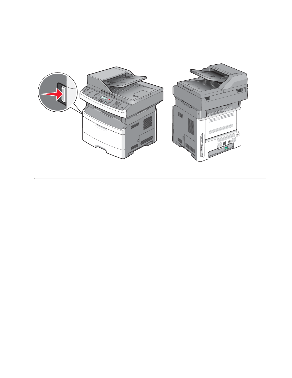
Locations . . . . . . . . . . . . . . . . . . . . . . . . . . . . . . . . . . . . . . . . . . . . . . . . . . . . . . . . . . . . . . . . . . . . . . . . . . 5-1
Front view . . . . . . . . . . . . . . . . . . . . . . . . . . . . . . . . . . . . . . . . . . . . . . . . . . . . . . . . . . . . . . . . . . . . . . 5-1
Rear view . . . . . . . . . . . . . . . . . . . . . . . . . . . . . . . . . . . . . . . . . . . . . . . . . . . . . . . . . . . . . . . . . . . . . . 5-2
Controller board connector pin values . . . . . . . . . . . . . . . . . . . . . . . . . . . . . . . . . . . . . . . . . . . . . . 5-3
Preventive mainte nan ce. . . . . . . . . . . . . . . . . . . . . . . . . . . . . . . . . . . . . . . . . . . . . . . . . . . . . . . . . . . . . . . . 6-1
Safety inspection guide . . . . . . . . . . . . . . . . . . . . . . . . . . . . . . . . . . . . . . . . . . . . . . . . . . . . . . . . . . . . . . . 6-1
Lubrication spec if ications . . . . . . . . . . . . . . . . . . . . . . . . . . . . . . . . . . . . . . . . . . . . . . . . . . . . . . . . . . . . . 6-1
Maintenance kits . . . . . . . . . . . . . . . . . . . . . . . . . . . . . . . . . . . . . . . . . . . . . . . . . . . . . . . . . . . . . . . . . . . . 6-1
Parts catalog . . . . . . . . . . . . . . . . . . . . . . . . . . . . . . . . . . . . . . . . . . . . . . . . . . . . . . . . . . . . . . . . . . . . . . . . . . . . 7-1
How to use this parts catalog . . . . . . . . . . . . . . . . . . . . . . . . . . . . . . . . . . . . . . . . . . . . . . . . . . . . . . . . . . 7-1
Assembly 1: Covers. . . . . . . . . . . . . . . . . . . . . . . . . . . . . . . . . . . . . . . . . . . . . . . . . . . . . . . . . . . . . . . . . 7-2
Assembly 2: Scanner. . . . . . . . . . . . . . . . . . . . . . . . . . . . . . . . . . . . . . . . . . . . . . . . . . . . . . . . . . . . . . . . 7-4
Assembly 3: Electronics . . . . . . . . . . . . . . . . . . . . . . . . . . . . . . . . . . . . . . . . . . . . . . . . . . . . . . . . . . . . . 7-7
Assembly 4: Frame. . . . . . . . . . . . . . . . . . . . . . . . . . . . . . . . . . . . . . . . . . . . . . . . . . . . . . . . . . . . . . . . . . 7-9
Assembly 5: Options . . . . . . . . . . . . . . . . . . . . . . . . . . . . . . . . . . . . . . . . . . . . . . . . . . . . . . . . . . . . . . . 7-11
vii

7013-XXX
Assembly 6: Power cords. . . . . . . . . . . . . . . . . . . . . . . . . . . . . . . . . . . . . . . . . . . . . . . . . . . . . . . . . . . 7-12
Index. . . . . . . . . . . . . . . . . . . . . . . . . . . . . . . . . . . . . . . . . . . . . . . . . . . . . . . . . . . . . . . . .I-1
Part number index. . . . . . . . . . . . . . . . . . . . . . . . . . . . . . . . . . . . . . . . . . . . . . . . . . . . . .I-5
viii Service Manual

Notices and safety information
The following laser notice labels may be affixed to this printer.
Laser no tice
The printer is certified in the U.S. to conform to the requi rements of DHHS 21 CFR Subchapter J for Class I (1)
laser products, and elsewhere is certified as a Class I laser product conforming to the requirements of IEC
60825-1.
Class I laser products are not considered to be hazardous. The printer contains internall y a Clas s IIIb (3b) laser
that is nomin all y a 5 milliwatt gallium arseni de laser operating i n the wavelength region of 770-795 nanom eters.
The laser system and pri nter are designed so there i s never any human access to las er radiation above a Class
I level during normal operation, user maintenance, or prescribed service condition.
Laser
Der Drucker erfüllt gemäß amt li cher Bestätigung der USA die Anfor derungen der Bestimmung DHHS
(Department of Health and Human Services) 21 CFR Teil J für Laserprodukte der Klasse I (1). I n anderen
Ländern gilt der Drucker als Laserprodukt der Klasse I, der die Anforderungen der IEC (International
Electrotechnical Commission) 60825-1 gemäß amtlicher Bestätigung erfül lt .
7013-XXX
Laserprodukte der Klasse I gelten als unschädlich. Im Inneren des Druckers befind e t si ch ein Laser der Klasse
IIIb (3b), bei dem es si ch um einen Galliumarsenlaser mit 5 Milliwatt handel t, der Wellen der Länge 770-795
Nanometer ausstr ahlt. Das Lasersystem und der Drucker sind so konzipiert, daß im Normalbetr ieb, bei der
Wartung durch den Benutzer oder bei ordnungsgemäßer Wartung durch den Kundendienst Laserbes tr ahlung,
die Klasse I übersteigen würde, Menschen keinesfalls erreicht.
Avis relatif à l’utilisation de laser
Pour les Etats-Unis : cette imprimante est ce rtifiée conforme aux provisions DHHS 21 CFR alinéa J conc ernant
les produits laser de Classe I (1). Pour les aut res pays : cette imprimant e répond aux normes IEC 60825-1
relatives aux produits laser de Classe I.
Les produits laser de Classe I sont considérés comme des produits non dangereux. Cette imprimante est
équipée d’un l aser de Classe IIIb (3b) (arséniur e de gallium d’une puissance nominal e de 5 milliwatts ) émettant
sur des longueurs d’onde comprises entre 770 et 795 nanomètres. L’imprimante et son système laser sont
conçus pour impossible, dans des conditions normales d’utilisation, d’entretien par l’utilisateur ou de révision,
l’exposition à des rayonnements laser supérieurs à des rayonnements de Classe I .
Avvertenze sui prodotti laser
Questa stampant e è certificata negli Stati Unit i per essere conforme ai requisit i del DHHS 21 CFR Sottocapitolo
J per i prodotti laser di classe 1 ed è certificat a negli altri Paesi come prodotto laser di classe 1 conforme ai
requisiti del la norma CEI 60825-1.
I prodotti laser di classe non sono consider at i pericol osi. La st ampant e contie ne al suo interno un laser d i classe
IIIb (3b) all’arseniuro di gall io della potenza di 5mW che opera sul la lunghezza d’ond a com presa tra 770 e 795
nanometri. Il sistema laser e la stampante sono stati proget tati in modo tale che le persone a contatto con la
stampante, durante il normale funzionamento, le operazioni di servizio o quelle di assistenza tecnica, non
ricevano radi azioni laser superi ori al livello della classe 1.
Notices and safety information ix

7013-XXX
Avisos sobre el láser
Se certifica que, en los EE.UU., esta impresora cumple los requisitos para los productos láser de Clase I (1)
establecidos en el su bcapítulo J de la norma CFR 21 del DHHS (Departamento de Sanid ad y Servicios) y, en
los demás países, reúne todas las condiciones expuestas en la norma IEC 60825-1 para productos láser de
Clase I (1).
Los productos láser de Clase I no se consideran peligrosos. La impresora contiene en su int eri or un láser de
Clase IIIb (3b) de arseniuro de gali o de funcionami ento nominal a 5 m ilivatios en una longitud de onda de 770 a
795 nanómetros. El sistema láser y la impresora están diseñados de forma que ninguna persona pueda verse
afectada por ni ngún ti po de radiación láser superior al nivel de la Clase I dur ante su uso normal, el
mantenimiento realizado por el usuario o cualquier otra situación de servici o técnico.
Declaração sobre Laser
A impressora e stá cer tific ada n os E.U.A . em conf ormidade com os r equisi tos da regu lamentaç ão DHHS 21 CFR
Subcapítulo J para a Clas se I (1) de produt os laser . Em outr os locai s, est á cer tific ada co mo um produ to laser da
Classe I, em conformidade com os requisitos da norma IEC 60825-1.
Os produtos lase r da Class e I não são cons id erados per igosos . Inte rnamen te, a impress ora contém um produ to
laser da Classe IIIb (3b), designado laser de arseneto de potássio, de 5 mill iwatts ,operando numa faixa de
comprimento de onda entre 770 e 795 nanómetros. O sistema e a impressora laser foram concebido s de forma
a nunca existir qualquer possiblidade de acesso humano a radiaç ão laser superior a um nível de Classe I
durante a operação nor m al, a manutenção feita pel o utilizador ou condições de assistência prescritas.
Laserinformatie
De printer voldoet aan de eisen die gesteld worden aan een laserprodukt van klasse I. Voor de Verenigde
Staten zijn deze eis en vastgelegd in DHHS 21 CFR Subchapter J, voor andere landen in IEC 60825-1.
Laserprodukten van klasse I worden niet als ongevaarlijk aangemerkt. De printer is voorzien van een laser van
klasse IIIb (3b), dat wil zeggen een gallium arsenide-laser van 5 milliwatt met een golflengte van 770-795
nanometer. Het laser gedee lte en de print er zijn zo ontworp en dat bij normaal gebr uik, bi j onder houd of repar atie
conform de voorschriften, nooi t bl ootstelling mogelijk is aan laserstr aling boven een niveau zoals
voorgeschr even is voor klasse 1.
Lasermeddelelse
Printeren er godkendt som et Klasse I-laserprodukt, i overenstemmelse med kravene i IEC 60825-1.
Klasse I-laserprodukter betragtes ikke som farlige. Printeren indeholder internt en Klasse IIIB (3b)-laser, der
nominelt er en 5 milli watt galliumarsenid laser, som arbejder på bølgelængdeområdet 770-795 nanometer.
Lasersystemet og printeren er udformet således, at mennesker aldrig udsættes for en laserstråling over Klasse
I-niveau ved nor m al dr ift, brugervedl igeholdelse ell er obligatoriske servi cebetingels er.
x Service Manual

Laserilmoitus
Tämä tulostin on sertif ioitu Yhdysvalloissa DHHS 21 CFR Subchapter J -standardin mukaiseksi luokan I (1) lasertuot teeksi ja muualla IEC 60825- 1 -st andardin mukaiseksi luokan I lasertuotteeksi.
Luokan I laser tuot teit a ei pi detä hai tall isi na. Tul ostimen sisäl l ä on luok an III b (3b) laser, joka o n ni mellist eholt aan
5 mW:n galliumarsenidilaser ja toimii 770 - 795 nanometrin aallonpituuksilla. Laserjärjestelmä ja tulost in ovat
rakenteelt aan sellaisia, et tä käyttäjä ei joudu altt iiksi luokkaa 1 suur em m all e säteilylle nor m aalin käytön,
ylläpidon tai huollon aikana.
Huomautu s las er laitteesta
Tämä kirjoi tin on Yh dysval loiss a luokan I (1) las erlai ttei den DHHS 21 CFR Subc hapt er J -määr ity ksen mukai nen
ja muualla luokan I laserlaitteiden IEC 60825-1 -määrityksen mukainen.
Luokan I laserlaitteiden ei katsota olevan vaarallisia käyttäjälle. Kirjoittimessa on sisäinen luokan IIIb (3b) 5
milliwatin gal liumarsenid il aser, joka toimii aalt oalueella 770 - 795 nanom etriä. Laserjärjestelmä ja kirjoitin on
suunniteltu siten, että käytt äjä ei altistu luokan I määrityksiä voimakkaammalle säteilylle kirj oittimen normaalin
toiminnan, käyttäjän tekemien huoltotoimien tai muiden huoltotoimien yhteydessä.
VARO! Avattaessa ja suojalukitus ohitettaessa olet alttiina näkymättömälle lasersäteilylle. Älä katso
säteeseen.
7013-XXX
VARNING! Osynlig laserst rålning när denna del är öppn ad och spärren är urkopplad. Betrakta ej strålen.
Laser-notis
Denna skrivare är i USA certifierad att motsvara kraven i DHHS 21 CFR, underparagraf J för laserprodukter av
Klass I (1). I andra länder uppfyller skrivaren kraven för laserprodukter av Klass I enligt kraven i IEC 60825-1.
Laserprodukter i Klass I anses ej hälsovådliga. Skriva ren har en inbyggd laser av Klas s II Ib (3b) som består av
en laserenhet av gal lium-arsenid på 5 mil li watt som arbetar i våglängdsområdet 770-795 nanom eter.
Lasersystem et och skrivaren är utfo rmade så att det aldrig finns risk för att någon pe rson utsätts för
laserstrå lning över Klass I-nivå vid normal användning, underhåll som utför s av användaren eller annan
föreskriv en serviceåtgärd.
Laser-melding
Skriveren er godkjent i USA etter kravene i DHHS 21 CFR, underkapittel J, for k lasse I (1) laserprodukter, og er
i andre land godkjent som et Klasse I-laser produkt i samsvar med krav ene i I EC 60825-1.
Klasse I-laserprodukte r er ikke å betrakte so m farlige. Skriveren inneholder inter nt en klasse IIIb (3b)-laser, s om
består av en gallium-arsenlaserenhet som avgir stråli ng i bølgelengdeomr ådet 770-795 nanometer .
Lasersystem et og skrive ren er utformet slik at personer aldri utsett es for la serstrål i ng ut over klasse I-n ivå under
vanlig bruk, vedlikehold som utføres av brukeren, ell er fo reskrevne serviceoperasjoner.
Notices and safety information xi
7013-XXX
Avís sobre el Làser
Segons ha estat cert ificat als Estats Units, aquesta impressor a compleix els requi sits de DHHS 21 CFR, apartat
J, pels productes làser de classe I (1), i segons ha estat cer tificat en alt res llocs, és un producte làser de classe
I que compleix els requisits d’IEC 60825-1.
Els productes l àser de classe I no es consideren perillosos. Aquesta impressora con té un làser de classe IIIb
(3b) d’arseniür de gal.li, nominalment de 5 mil.liwats, i funciona a la regió de longi tud d’ ona de 770-795
nanòmetres. El sistema làser i la impressora han sigut concebuts de manera que mai hi hagi exposició a la
radiació làser per sobre d’un nivell de classe I durant una operaci ó normal, durant les tasques de manteniment
d’usuari ni durant els serveis que satisfacin les condicions prescrites.
xii Service Manual
7013-XXX
Notices and safety inf ormation xiii

7013-XXX
xiv Service Manual
Safety information
CAUTION
This product cont ains a lithi um battery. THERE IS A RISK OF EXPL OSION IF THE BATTERY
IS REPLACED BY AN INCORRECT TYPE. Discard used batteries according to the battery
manufacturer’s instructions and local regulations.
• The safety of this product is based on testing and approvals of the original design and speci fi c
components. The man ufacturer is not res ponsible for safety in the event of use of unauthorized
replacement parts.
• The maintenance inf ormation for this product has been prepared for use by a professional ser vice person
and is not intended to be used by others.
• There may be an increased risk of electric shock and personal injury during disassembly and servicing of
this product. Professional service personnel should understand this and take necessary precautions.
• CAUTION: When you see this symbol, there i s a danger from hazardous volta ge i n the area of the
product where you a re work ing. Unp lug th e product be fore y ou begin, or us e cau tion i f th e product
must receive power in order to perform the task.
7013-XXX
Consignes de sécurité
• La sécurité de ce pro duit repose sur des tests et des
agréations por tant sur sa conception d' origine et sur des composants particuliers. Le fabricant n'assume
aucune respon sabilité concernant la sécurité en cas d'ut ilisation de piè ces de rechange non agréées.
• Les consignes d'entretien et de réparation de ce produit s'adressent unique me nt à un personnel de
maintenance qualifié.
• Le démontage et l'entretien de ce produit pouvant présenter certains risques électriques, le personnel
d'entretien qualifié devra prendre toutes les précautions nécessaires.
• ATTENTION : Ce symbole indique la prés ence d'une tension dangereuse dans la partie du
produit sur laquelle vous travaillez. Débranchez le produit avant de commencer ou fai tes preuve
de vigilance si l' exécution de la tâche exi ge que le produit reste sous tension.
Norme di sicurezza
• La sicurezza del prodotto si basa sui test e sull'approvazione del progetto originale e dei componenti
specifici. Il produttore non è resp onsabile per la sicur ezza in caso di sostituzione non autorizzata delle
parti.
• Le informazion i riguardanti la manutenzione di questo prodotto sono indirizzate soltanto al pers onale di
assistenza autorizzato.
• Durante lo smontaggio e la manutenzione di questo prodotto,
il rischio di subire scosse elettriche e danni alla persona è più elevato. Il personale di assistenza
autorizzat o deve, quindi, adott are le precauzioni necessarie.
• ATTENZIONE: Questo simbolo indica la presenza di tensione pericolosa nell'area del prodotto.
Scollegare il pr odotto prima di iniziare o usare cautela se il prodotto deve essere alimentato per
eseguire l'intervento.
Safety information xv

7013-XXX
Sicherheitshinweise
• Die Sicherheit di eses Produkts basiert auf Tests und Zulassungen des ursprünglichen Mode ll s und
bestimmter Baut eil e. Bei Verwendung nicht genehmigter Ersatzteile wird vom Hersteller keine
Verantwortung oder Haftung für die Sicherheit übernommen.
• Die Wartungsinformationen für dieses Produkt sind ausschl ießlich für die Verwendung durch einen
Wartungsfachmann bestimmt.
• Während des Auseinandernehmens und der Wartung des Geräts besteht ein zus ätzliches Risiko eines
elektrischen Schlags und körperlicher Verletzung. Das zuständige Fachpersonal sollte entsprechende
Vorsichtsmaßnahmen treffen.
• ACHTUNG: Dieses Symbol weist auf eine gefährliche elektrische Spannung hin, die i n diesem
Bereich des Produkts auf tret en kann. Zieh en Sie vor den Arbeit en am Gerät den Netzsteck er des
Geräts, bzw. arbeiten Sie mit große r Vor sicht, wenn das Produkt für die Ausführung der Arbeiten
an den Strom angeschlossen sein muß.
Pautas de Seguridad
• La seguridad de este producto se basa en pruebas y aprobaciones del diseño original y componentes
específico s. El fabri cante no es responsabl e de la seguridad en caso de uso de piezas de repuesto no
autorizadas.
• La información sobre el mantenimiento de este producto está dirigida exclusivamente al personal
cualificado de mantenimiento.
• Existe mayor riesgo de de scarga e léc trica y de dañ os pe rsonal es du rante e l desmont aj e y la r eparaci ón de
la máquina. El personal cualificado debe ser consciente de este peligro y tomar las precauciones
necesarias.
• PRECAUCIÓN: este símbolo indica que el voltaje de la parte del equi po con la que está
trabajando es peligroso. Antes de empez ar, desenchufe el equipo o te nga cuidado si, para
trabajar con él, debe conectarlo.
Inform a çõ es de Segurança
• A segurança deste produto baseia-se em testes e aprovações do modelo ori ginal e de componentes
específico s. O fabr icante não é responsá vel pela segunrança, no caso de uso de peças de substit uição
não autorizadas.
• As informações de segurança relativas a este produto destinam-se a profissionais destes serviços e não
devem ser utilizadas por outras pessoas.
• Risco de choques eléctricos e ferimentos graves durante a desmontagem e manutenção deste produto.
Os profissionais destes serviços devem estar avisados deste facto e tomar os cuidados necessários.
• CUIDADO: Quando vir este símbolo, existe a possível presença de um a potencial tensão
perigosa na zona do produto em que está a trabalhar . Ant es de com eçar, desligue o produt o da
tomada eléctr ica ou seja cu ida doso caso o pr oduto t enha de estar liga do à c orrent e eléc tric a para
realizar a taref a necessária.
xvi Service Manual
Informació de Seguretat
• La seguretat d'aquest producte es basa en l' avaluació i aprovació del disseny original i els components
específics .
El fabricant no es fa responsable de les qüestions de
seguretat si s'u ti litzen peces de recanvi no autoritzades.
• La informació pel ma nteniment d’aquest producte està orient ada exclusivament a professionals i no està
destinada
a ningú que no ho sigui.
• El risc de xoc elèctric i de danys personals pot augmentar durant el procés de desmuntatge i de servei
d’aquest producte. El personal professional ha d’estar-ne assabentat i prendre
les mesures con venients.
• PRECAUCIÓ: aquest símbol indica que el voltatge de la part de l'equip amb la qual esteu
treballan t és perill ós. Abans de començ ar, desendol leu l'equi p o extremeu les precauc ions si, per
treballar am b l'equip, l'heu de connect ar.
7013-XXX
Safety information xvii

7013-XXX
Preface
This manual contains maintenance procedures for service personnel. It is divided into the following chapters:
1. Gener a l in fo r m a ti o n contains a general description of the printer and the maintenance approach used to
repair it. Speci al tools and test equip me nt, as well as general environmental and safety instructions, are
discussed.
2. Diagnostic information contains an error indicator table, sym ptom tables, and service checks used to
isolate failing field replaceable units (FRUs).
3. Diagnostic aids con tai ns tests and checks used to locate or repeat symp toms of printer probl ems .
4. Rep ai r info rmation provides instructions for maki ng printer adjustments and removing and installing
FRUs.
5. Connector locations uses illustrations to identify the connec tor locations and test points on the printer .
6. Preventive maintenance contains the lubrication specif ications and recomme ndations to prevent
problems.
7. Parts catalog contains illustra ti ons and part numbers for individual FRUs.
Appendix A contains service tips and inf ormation.
Appendix B contains representative print samples .
Change history
Revision date Updates
2014/01/10 Added a note for the Scanner sensor tests in the Diagnostic Aids chapter.
2013/07/16 Updated the Media ACM ASM feeder removal —T he me dia feed clutch should only be
2013/07/01 Replaced 40X5612 with 40X900 0 (Assembly 3: Electronics).
2013/06/03 Registration under Diagnostics menu:
2012/05/06 • Removed logo from namplate cover illustration (page 7-2).
2012/9/19 Changed ADF separator pad PN from 40X5472 to 40X8419.
2012/08/07/ Added PN 40X5961for the Operator panel X264/X364 (DBCS) under “Scanner” on
2012/06/04 Corrected the description for PN 40X5617 to “Operator panel X264/X364” from “Operator
2012/05/02 Replaced all ref erences o f 4 0X5471 to 4 0X7545 for t he ADF separ ator r oll in “ Scanne r” on
2011/10/28 Added this warning: “Warni ng: Do not strip the insulation off the red and black wires. The
2011/9/14 Revised the media feed clutch assembly removal procedure in “Media feed clutch
loosened.
• Removed the Skew menu item.
• Added Right margin menu item and values.
• Added l ogo to nameplate cover ill ustration (page 7-4).
page 7-5.
panel X234/X364” under
page 7-5 and in “Maintenance kits” on page 6-1
connectors will not work if the insulation is removed,” in step 8 of
removal” on page 4-51.
removal” on page 4-51.
“Scanner” on page 7-5.
“Media feed clutch
xviii Service Manual
Conventions
CAUTION
A caution identifies something that might cause a servicer harm.
CAUTION
This type of caution i ndicates there is a danger from hazardous voltage in t he area of the
product where you are working. Unplug the product befor e you begin, or use caution i f th e
product must recei ve power in order to perform the task.
CAUTION
This type of caution i ndicates a hot surface.
CAUTION
This type of caution i ndicates a tipping hazar d.
Note: A note provides additional information.
Warning: A warning identi fi es something that might damage the product hardware or software.
There are several types of caution statements:
7013-XXX
Conventions xix

7013-XXX
xx Service Manual
1. General in formation
The Lexmark™ X364dw, X364dn , X363dn, and X264dn are monochro me laser printers designed for single
users or small workgroups.
7013-XXX
Maintenance approach
The diagnostic information in this manual leads to the correct field replaceable unit (FRU) or part. Use the error
code charts, sympt om index, and service checks to determine the symptom and repair the failure. See
“Diagnostics i nformation” on page 2- 1 for more inf ormation. See “Repair information” on page 4-1 to help
identify parts. After completing the repair, perform tests as needed to verify the repair.
General information 1-1
7013-XXX
Shortcuts
3
DEF
6
MNO
9
WXYZ
#
2
ABC
5
JKL
8
TUV
0
1
@
!.
4
PQRS
7
*
Fax
Redial/Pause
Resolution
Options
Hook
Select
Start
Stop/Cancel
Menu
Back
Copy
Copies
Scale
Options
Content
Darkness
Duplex/2-Sided
Text
Text/Photo
Photo
CopyCopy
Scan/EmailScan/Email
Fax
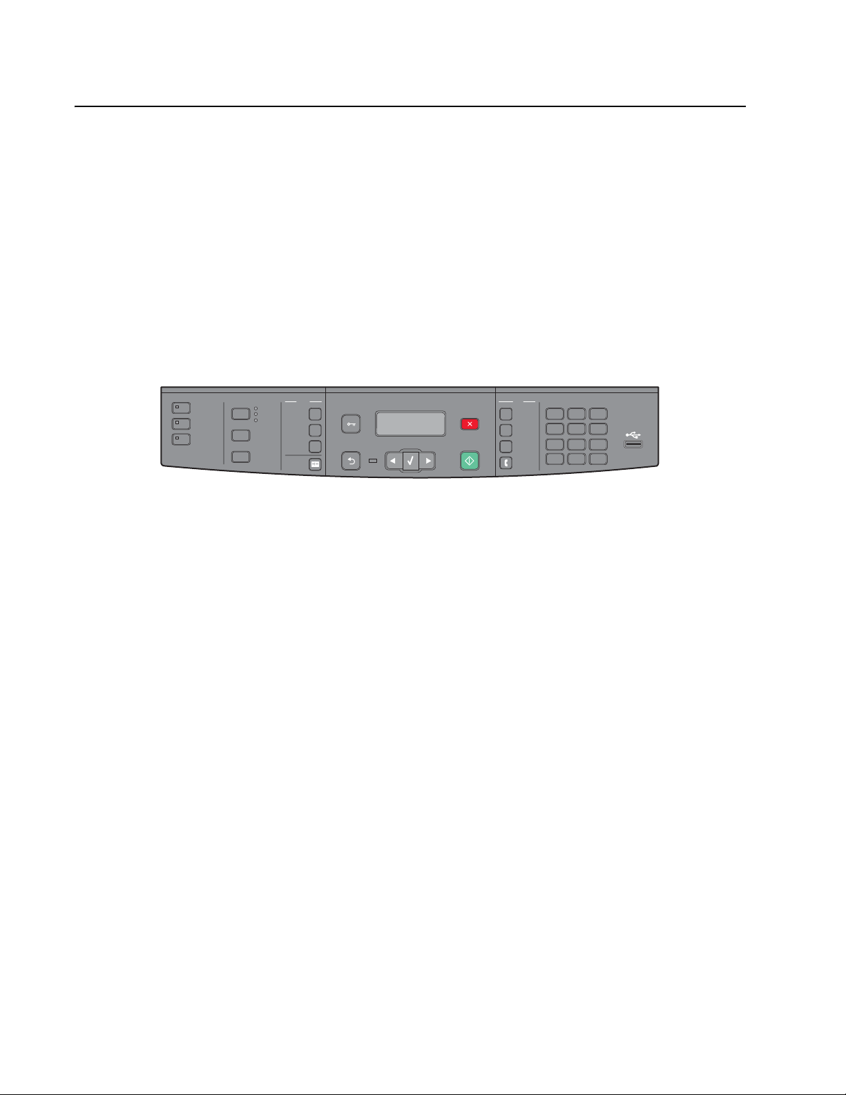
Overview of the operator panel
The operator panel is divided into three sections:
• Selections and settings area
• Display area
• Keypad area
Selections and sett ings contains ten butt ons (Copy, Scan/Email, Fax, Content, Darkness, Duplex/2-sided,
Copies, Scale, O ption s, and Addre ss boo k) and thr ee lig hts (Text , Text /Photo, and Photo) that l ight up t o displ ay
the chosen content option.
The display area contains seven buttons (Menu, Back, Left arrow, Select, Right arrow, Start, and Stop/Cancel),
an indicator light, and a 2-line liquid crystal display (LCD) that shows text.
The keypad area cont ai ns fi ve butto ns (Redi al/Paus e, Res olution, Opt ions, Ho ok, and Shor tcut s), a key pad, and
a USB port.
For more information on the operator panel, see “Overview of the operator panel and menus” on page 2-2.
1-2 Service Manual

Specifications
Memory
7013-XXX
Item
Standard memory 64MB 128MB 128MB 128MB
Maximum memory 64MB 128MB 128MB 128MB
Optional memory
8MB x x x x
16MB x x x x
32MB x x x x
64MB x x x x
128MB x x x x
256MB x x x x
512MB x x x x
Standard flash memory x x x x
Maximum flash memory 64MB 64MB 64MB 64MB
Optional flash memory cards
32MB card x x x x
7013-235
Lexmark X264dn
7013-432
Lexmark X363dn
7013-436
Lexmark X364dn
7013-43W
Lexmark X364dw
64MB card ✔ ✔ ✔ ✔
128MV card x x x x
256MB card x x x x
Available daughter card slots
Font card ✔ ✔ ✔ ✔
DLE x x x x
General information 1-3

7013-XXX
Print quality setti ngs
Item
Image enhancement technology (IET)
2 Bits /p el ✔ ✔ ✔ ✔
4 Bits /p el ✔ ✔ ✔ ✔
Print resolution
300 dpi ✔ ✔ ✔ ✔
600 dpi
• 1200 image qualit y (600
dpi with 2 bits/pel)
• 2400 image qualit y (600
dpi with 4 bits/pel)
• 4800 color quality (600 dpi
with 4 bits/pel)
1200 dpi ✔ ✔ ✔ ✔
7013-235
Lexmark X264dn
✔ ✔ ✔ ✔
✔ ✔ ✔ ✔
✔ ✔ ✔ ✔
x x x x
7013-432
Lexmark X363dn
7013-436
Lexmark X364dn
7013-43W
Lexmark X364dw
1-4 Service Manual

Compatibility and connectivity
7013-XXX
Item
Datastreams
XPS x x x x
PCL 6 emulation ✔ ✔ ✔ ✔
PostScript level 3 emulation ✔ ✔ ✔ ✔
NPAP ✔ ✔ ✔ ✔
PJL ✔ ✔ ✔ ✔
PPDS ✔ ✔ ✔ ✔
PDF (version 1.6) x ✔ ✔ ✔
PictBridge x x x x
HTML (including DBCS) x x x x
Direcetimage x ✔ ✔ ✔
Host based printing/graphics device interface
• Version 1 x x x x
• Version 2 x x x x
7013-235
Lexmark X264dn
7013-432
Lexmark X363dn
7013-436
Lexmark X364dn
7013-43W
Lexmark X364dw
• Version 3 (mono) ✔ ✔ ✔ ✔
Compatibility Windows/
Standard connecti ons
Serial interface x x x x
Ethernet 10/100 Base T ✔ ✔ ✔ ✔
USB-B (hi-speed) device port ✔ ✔ ✔ ✔
Fax functionality x x ✔ ✔
USB-A front host port
(low/full speed)
USB-A rear host port x x x x
802.11n wireless networking card x x x ✔
Optional connections x x x x
Macintosh/Linux
x ✔ ✔ ✔
Windows/
Macintosh/Linux
Windows/
Macintosh/Linux
Windows/
Macintosh/Linux
General information 1-5

7013-XXX
Media trays and supply capacity
Item
Standard input sources
Integrated 250-sheet tray ✔ ✔ ✔ ✔
50-sheet MP feeder x ✔ ✔ ✔
1-sheet manual feed slot ✔ x x x
Optional input sources
250-sheet drawer ✔ ✔ ✔ ✔
550-sheet drawer ✔ ✔ ✔ ✔
Manual/integrated print duplex Integrated Integrated Integrated Integrated
ADF scanner type Simplex Recirculating
Envelope conditioning x x x x
Instant on fuser ✔ ✔ ✔ ✔
Standard output sources
150-sheet sensing bin ✔ ✔ ✔ ✔
Toner and photoconductor
7013-235
Lexmark X264dn
7013-432
Lexmark X363dn
duplex
7013-436
Lexmark X364dn
Recirculating
duplex
7013-43W
Lexmark X364dw
Recirculating
duplex
Toner cartridge 1,500 standard
pages SWE¹
X360 Series standar d yield x 3,500 standard pages SWE¹
High toner cartri dge x 9,000 standard pages¹
Photoconductor kit Up to 30,000 pages²
¹ Declared value in accordance with ISO/IEC 1975 2
² Up to 30,000 pages, based on an average of 3 pages per job and approximately 5% coverage per page. Yields may
vary based on customer usage.
3,000 standard pages SWE¹
1-6 Service Manual

Types of print media
Note: Ensure trays are properly loaded. Never mix media types wit hin a tray.
Source Sizes Types Weight Input capacity* (sheets)
7013-XXX
Input tray 1
(250-sheet tray)
2nd Drawer option
(250-sheet dr awer,
550-sheet drawer)
Manual feeder slo t A4, A5, A6,JIS¹-B5,
A4, A5, A6,JIS¹-B5,
letter, legal, executive,
oficio (Me x ic o )² , fo lio ² ,
statement, uni versal
A4, A5, JIS¹-B5, letter ,
legal, executive, oficio
(Mexico)², folio²,
statement
letter, legal, executive,
oficio (Me x ic o )² , fo lio ² ,
statement, uni versal
Plain paper,
transparency,
recycled, labels,
bond, letterhead,
preprinte d, colored
paper, light paper,
heavy paper,
rough/cotton,
custom type [x]
Plain paper,
recycled, labels,
bond, letterhead,
preprinte d, colored
paper, light paper,
heavy paper,
rough/cotton,
custom ty p e [x]]
Plain paper,
transparency,
recycled, labels,
bond, letterhead,
preprinte d, colored
paper, light paper,
heavy paper,
rough/cotton,
custom type [x]
Card stock*** • 120-163 g/m²
60-9 0 g/m²
(16-24 lb)
60-9 0 g/m²
(16-24 lb)
60-1 63 g/m²
(16-43 lb)
(16-43 lb)
Index Bristol
• 75-163 g/m²
(46-100 lb)
Tag
• 150 paper
• 50 la bels**
• 10 transparencies
• 1 paper
• 1 la bels**
• 1 paper
• 1 la bel* *
• 1 transparency
1
7 ¾, 9, 10, DL, C5, B5,
other
Manual paper A4, A5, A6,JIS¹-B5,
letter, legal, executive,
oficio (Me x ic o )² , fo lio ² ,
statement, uni versal
Manual envelope 7 ¾, 9, 10, DL, C5, B5,
other
Envelopes, rou gh
envelopes
Plain paper,
transparency,
recycled, labels,
bond, letterhead,
preprinte d, colored
paper, light paper,
heavy paper,
rough/cotton,
custom type [x]
Card stock*** • 120-163 g/m²
Envelopes, rou gh
envelopes, cus tom
type [x]
75 g/m² (20 lb) 1
60-1 63 g/m²
(16-43 lb)
(16-43 lb)
Index Bristol
• 75-163 g/m²
(46-100 lb)
Tag
75 g/m² (20 lb) 1
• 1 paper
• 1 la bel* *
• 1 transparency
1
General information 1-7

7013-XXX
Source Sizes Types Weight Input capacity* (sheets)
Duplex A4, letter, legal, oficio
Automatic document
feeder (ADF)
Multipurpose feeder A4, A5, A6,JIS¹-B5,
(Mexico), fo li o
A4, A5, JIS¹-B5, letter ,
legal, executive, oficio
(Mexico), fo li o,
statement, uni versal,
custom scan typ e [x]
letter, legal, executive,
oficio (Mexico), folio,
statement, uni versal
7 ¾, 9, 10, DL, C5, B5,
other
Plain paper,
recycled, bond,
letterhead,
preprinte d, colored
paper, light paper,
heavy paper,
custom type [x]
Accepts any media type supported by the print engine
Plain paper,
transparency,
recycled, labels,
bond, letterhead,
preprinte d, colored
paper, light paper,
heavy paper,
rough/cotton,
custom type [x]
Card stock*** • 120-163 g/m²
Envelopes
Rough envelopes
60-9 0 g/m²
(16-24 lb)
60-1 63 g/m²
(16-43 lb)
(16-43 lb)
Index Bristol
• 75-163 g/m²
(46-100 lb)
Tag
75 g/m² (20 lb) 7
• 250 paper
• 550 paper
• 50 paper
• 15 la bels**
• 10 transparencies
20
Flatbed Business card, 3 X 5,
4 X 6, A4, A5, JIS¹-B5,
letter, executive,
statement, uni versal,
custom scan typ e [x]
* Capacity for 20 lb print media, unless otherwise noted.
** Use for occasional printing only.
*** Grain short is recommended. Use rear exit for best results.
¹Japanese Indust ry Standard
Accepts any media type supported by the print engine
1-8 Service Manual

Digital imaging specifications
General specifications
ADF Scan sp eed
Simplex ADF - Up to 22 ppm
ADF Document handling
ADF input capacity - 50 sheet s
ADF output capacity - 50 sheets
ADF document width - 4.9” (125mm) to 8.5” (216mm)
ADF document length - 5” (127mm ) to 14.0” (356mm)
Resolution and color depth
• Resolution - 600 dpi opt ical
• Color depth - 24 bit RGB output, 8 bit/channel
7013-XXX
Flatbed document specifications
• Document size- Up to A4 and lett er
4.5” x 5.5” to 8.5”x11” (SEF)
Flatbed speed
3 seconds to scan, 3 seconds to return
Scanner operating environments
• Temperature - 10C to 35C
• Humidity - 15% RH to 85% RH
Storage en vironments
• Temperature - -20C to 43C
• Humidity - 5% RH to 95% RH
Tilt
This device should operate within the stated parameters when it is level wit hin 10mm from front to back and
10mm side to side.
General information 1-9

7013-XXX
Scan and copy specific specifications
Duplex scan
Duplex and copy is available only on X360 Series machines.
Scan file output formats
• TIFF
• JPEG
• PDF
Supported compressions
• PDF - (1 bit,- JBIG2 CCIT G4, Flate), (8/24 bit - Flate JPEG)
• TIFF - (1 bit - CCITT G4), (8/24 bit - Packbit s, LZW)
• JPG - (8/ 24 bi t-JPG)
Supported scan destinations
• Temporary profi le from a user’s PC
• Scan to PC via network TWAIN
• Scan to PC using Web applet
• Scan to E-Mail
• Scan to USB (X364 models only)
• Lexmark Scan Center
Multiple copies
999 copies maximum
Reduce/Enlarge (copy only)
-25% to 400%
1-10 Service Manual

Fax specificat ions
Phone network connectivity
Phone networks types supported PSTN or analog PABX (RJ-11 )
ITU COMPATIBILITY
Standard Resolution
Fine
Superfine
Ultra fine
Coding
Mode m sp ee d V.34 2400-33,600 BPS
Compression MH, MR , M MR , J P E G
Error correction ITU T.30
Line interface selection
Modular Plug
Out Band Signal Level
Input Level Range
Ring Detection
Group 3/ECM
8 x 3.85 pels/mm (200X100dpi) (204x98)
8 x 7.7 pels/mm (200X200dpi) (204x 196)
11.8 x 11.8 pels/mm(300x300 dpi) (204x391)
15.7 x 15.7 pels/mm (400x400 dpi) (408x391)
ITU T.4 and T.6(MH, MR, MMR, JPEG)
V.17 7200-14,400 BPS
V.27 2400-4800 BPS
V.29 7200-9600 B PS
Dual RJ-11C
Guaranteed North American and Europe PTT standard
-16dBm ~ -59dBm
Complies with all regulatory requirements
7013-XXX
Fax resolutions
Receive 200x100 dpi, 200x200 dpi, 300x300 dpi, 400x400 dpi, 204x98 dpi, 204x196
Send 200x100dpi, 200x200 dpi, 300x300 dpi
dpi, 20 4x391 dpi, 408x391 dpi
Miscellaneous FAX specifications
Fax memory 4 MB Flash (More than 320 pages based on ITU chart #1)
Speed dial Yes. 999 entries
Transmission Approximatel y 3 seconds per page
Color fax Yes
Fax from PC Yes. Supported using Po stScript driver for both local an d network attach modes.
Caller ID Yes
Junk FAX blocking Yes - based on caller ID and remote station ID
Tone/Pulse Tone: Default, Pulse: Yes
Fax forward Yes
Broadcasting Yes. 12 destinations
External phone in terface Yes
Manual mode Yes
Fax short cuts Yes.
Fax content Text, text/photo, photo
Fax perseveration Yes
Halftoning Yes
User selectabl e parameters are stored in NVRAM.
General information 1-11

7013-XXX
Tools
The removal and adjust m ent procedures require the following tool s and equipment:
• Spring hook
• Needle nose pliers
• Volt-ohmmeter
• #1 and #2 Phillips screwdr iv e r
• Slotted screwdriver
Acronyms
ac Alternating Cur r ent
ACM Autocompensator Mechanism (or paper feed)
ADF Automatic document feeder
AFE Analog front end
AIO All-In-One
APS Automatic Paper Size
ASIC Application Specific Integrated Circui t
BLDC Brushless DC Motor
BOR Black Only Retract
BUD Belt up down
C Cyan
CCD Charge-Couple Device
CCFL Cold Cathode Fluorescent Lamp
CCW Counter clockwise
CDB Command Descriptor Blocks
CMYK Cyan yellow magenta black
CPU Central processing unit
CRC Cyclic redundancy check
CRU Customer Replaceable Unit
CSU Customer Setup
CW Cl ockwise
DBCS Double byte character set
dc Direct Current
DIMM Dual Inline Memory Module
DLE Downloadable emulator
DRAM Dynamic random access memory
DVM Digital mu lt im e te r
ECC Error correcting code
ECM Error correct ion mode
EDO Enhanced Data Out
EEPROM Electrical Erasable Programmable Read-Only Memory
ENA External Network Adapter
EOL End of line
EP Electrophotographic process
EPROM Erasable programmable read-only memory
ESD Electrostatic Discharge
FB Flatbed
FD Facedown
FRU Field replaceable unit
FU Face up
1-12 Service Manual

GB Gigabyte
GFI G round Fault Interrupter
GHz Gigahertz
HBP Host Based Printing
HCF High-capacity feeder
HCIT High-capacity Input Tray
HCOF High-Capacity Output Finisher
HCPF High-capacity feeder
HTML Hypertext markup language
HV High Voltage
HVPS High voltage power supply
HVU High voltage unit
Hz Hertz
INTL International
ITC Internal Tray Card
ITU Image Transfer Unit
K Black (Key)
LAN Local area network
LASER Light amplification by stimulated emission of radiation
LCD Liquid cry st al dis p la y
LCM Liquid Crystal Module
LD Laser Diode
LED Light emitting dio de
LEF Long edge feed
LES Lexmark Embedded Solution (applications)
LSU Laser Scanning Unit
LV Low Voltage
LVPS Low voltage power supply
M Magenta
MB Megabyte
MDC Motor Driver Control
MFD Multifunction Device
MFP Multifunction Printer
MH M essage handling
MIF Moto r in te rface
mm Millimeter
MMR Modified modified read
MPF Multipurpose feeder
MR M odem ready
MROM Masked Read Only Memory
MS Microswitch
NAND NAND (usage: NAND gate)
NVM Nonvolatile Mem ory
NVRAM Nonvolatile Random Acc ess Mem ory
OCF Operator correctable failure
OCR Oil coating roll
OEM Original Equipment Manufacturer
OHP Overhead projector
OPC Optical photo conductor
OPT Optical Sensor
PC Photoconductor
PDF Portable Document Format
PICS Problem isolation charts
PIN Personal identification number
7013-XXX
General information 1-13

7013-XXX
PIXEL Picture element
PJL Printer Job Language
POR Power-on reset
POST Power-on self test
PPDS Personal Printer Data Stream
ppm Pages per minute
PQET Print Quality Enhancement Technology
PRC Peoples' Republic of China
PSC Parallel Synchronous Communications
PSD Position Sensing Device
PSO Participating Standards Organization
PWM Pulse Width Modulation
RAM Random access memory
RFID Radio frequency identification
RH Relative humidity
RIP Raster image processor
ROM Read-only memory
ROS Read-only storage
RPM Revolutions Per Minute
SCC Scanner Control Card
SDRAM Synchronous Dynamic Random Access Memory
SEF Short edge feed
SIMM Single Inline Memory Module
SOL Solenoid
SOS Start of scan
SRAM Static random access memory
TAR Toner Add Roll
TPS Toner Patch Sensing
TTM Tandem Tray Module
TVOC Total Volatile Organic Compound
UAT Universally Adjustable Tray
UPR Used Parts Return
USB Universal Serial Bus
V Volts
V ac Volts alternating curren t
V dc Volts direct current
VOIP Voice over internet protocol
VOM Volt Ohmmeter
VTB Vacuum Transport Belt
XPS XML Paper Specification
Y Yellow
1-14 Service Manual

2. Diagnostics information
Shortcuts
3
DEF
6
MNO
9
WXYZ
#
2
ABC
5
JKL
8
TUV
0
1
@
!.
4
PQRS
7
*
Fax
Redial/Pause
Resolution
Options
Hook
Select
Start
Stop/Cancel
Menu
Back
Copy
Copies
Scale
Options
Content
Darkness
Duplex/2-Sided
Text
Text/Photo
Photo
Copy
Scan/Email
Fax
Start
CAUTION: Unplug power from the printe r bef ore connecting or disconnecting any cable,
assembly, or el ectr onic car d. Thi s is a pr eca ution f or per sonal sa fety an d to prevent damage to t he
printer.
This chapter cont ains the codes and diagnostic tools to aid in provi ding corrective action for a malfunctioning
printer. To deter m ine the corrective ac ti on to repair a printer, look for the following info rmation:
• A description of a problem. See “Symptom tables” on page 2-23.
• Information from the oper ator panel o f t he printer. See “Overview of the operator panel and menus” on
page 2-2.
7013-XXX
Power–On Self Test (POST) sequence
The following is an example of the events that oc cur dur ing the POR sequence when the printer is turned on.
1. While code is being loaded into DRAM, dots scroll across the operator panel.
2. A screen is displayed with t he memo ry and processor speed. A typi cal example of this message is:
*xxx MB 267 Mhz
3. Please wait is displayed.
4. Busy is displayed.
5. Close Door will be displayed if the cover is open.
6. Any cartridge errors, such as Defective Cartridge, are displayed.
7. Applicable maintenance messages are displayed.
8. Applicable toner low messages are displayed.
9. The printer displays Ready.
Diagnostics information 2-1

7013-XXX
Shortcuts
3
DEF
6
MNO
9
WXYZ
#
2
ABC
5
JKL
8
TUV
0
1
@
!.
4
PQRS
7
*
Fax
Redial/Pause
Resolution
Options
Hook
Select
Start
Stop/Cancel
Menu
Back
Copy
Copies
Scale
Options
Content
Darkness
Duplex/2-Sided
Text
Text/Photo
Photo
CopyCopy
Scan/Email
Fax
1
2
3
4
5
6
7
8
10
9
11
13
12
14
15
16
17
19
18
26
25
24
23
22
21
20
Copy
Content
Text
Text/Photo
Photo
Copies
Overview of the operator panel and menus
Understanding the operator panel
The printer operator panel has a four-l ine, back lit, grayscale display that can show both graphics and text . The
Mode selection, job setup, Back, and Menu buttons are located to the left of the display, the navigation buttons
are located below the display, and the start buttons, stop button, and nume ric pad are located to the right of the
display. In addition, there is a USB jack that enables printing of certain graphics formats as well as enabling
PictBridge functionality.
Operator panel buttons
Number Part Button Function
1
2 Content button • Enhances copy, scan, e-mail, or fax quality
3 Copies button Enters the number of copies to print
4 Menu button Enters the administrative menus
5 LCD display screen Displays:
Copy button Enables copy mode
• Choose from Text, Text/Photo, or Photo
• Scanning, copying, faxing, and printing options
• Status messages
• Error messages
2-2 Service Manual

Number Part Button Function
Redial/PauseRedial/Pause
Shortcuts
#
Resolution
Options
7013-XXX
6
Stop/Cancel button Stops/cancel s all printer activity
7 Redial/Pause button • Press once t o cause a two- or three-second dial pause
in a fax number.
• Press to redial a fax number
8 Keypad Enters numbers, letters, or symbols on the LCD display
9 Front USB port Scans to a flash drive or prints supported file types
Note:
• The front USB port is not available on all models.
• When a USB fl ash m em ory device is inserted int o the
printer, the printer can only scan to the USB device or
print files from the USB device. All other printer
functions ar e unavailable.
10 Shortcuts button Enters the shortcut screen
11 Resolution button Selects a dpi value for the scan (fax only button)
Note: Press the right or left arrow buttons to scroll throug h
the values, and then press select to enter a val ue.
12
Fax options button Changes the Original Siz e, Broadcast, Delayed Send, and
Cancel settings
Note: The fax options b utton is no t available on all mode ls.
13
Hook button Press once to take the tel ephone line off-hook. Press a
second time to hang up the lin e.
Note: The hook button is not available on all models.
14
Start button Starts a copy or scan job
15 Right arrow button Sc rol ls to the right on the display screen
Diagnostics information 2-3

7013-XXX
Options
Scan/Email
Duplex/2-Sided
Darkness
Fax
Scan/Email
Number Part Button Function
16
Select button Accept s me nu selections and setti ngs
17 Left arrow button Scrolls to the left on the display screen
18 Indicator light Indicates prin ter status:
• Off: the printer is off
• Bl inking green: the printer is warming up, proc essing
data, or printi ng
• Sol id green: the printer is on, but idle
• Bl inking red: operator intervention is needed
19 Back button Returns one screen at a time t o the Ready screen
Note: If a flash dri ve is connected and the USB menu is
displayed, then an error beep will sound when the back
button is pressed.
20
Address book button Opens the address book
21 Copy options button Changes Original Size, Paper Source, and Collate settings
22 Scale button Changes the size of the copied document to fit into the
currently selected media size
23 Duplex 2-sided button Scans or prints on both si des of the media.
Note: The duplex 2-sided button is not avail able on all
models.
24
Darkness button Adjusts the current darkness settings
25 Fax button Enters the fax function
Note: The fax button is not available on all models.
26
Scan/Email button Enters the scan or scan-to-e-mail function
2-4 Service Manual

Diagram of the printer menus
Paper Menu
Paper Source
Paper Size
Paper Type
Custom Types
Universal Setup
Substitute Size
Paper Texture
Paper Weight
Paper Loading
PostScript Menu
Print PS Error
USB Menu
Standa r d US B
Finishing Menu
Duplex
Duplex Bind
Copies
Blank Pages
Collation
Separator Sheets
Separator Source
Multipage Print
Multipage Order
Multipage View
Multipage Border
Job Menu
Reset Printe r
Utilities Menu
Quick Demo
Print Menus
Print Stats
Print Net Setup
Print Fonts
Print Demo
Factory Defaults
Hex Trace
Quality Menu
Print Resolution
Toner Darkness
Small Font Enh.
Setup Menu
Eco-Mode
Quiet Mode
Printer Lang uage
Power Saver
Resource Save
Print Timeout
Wait Timeout
Auto Continue
Jam Recovery
Page Protect
Print area
Display Language
Toner Alarm
PCL Emul Menu
Font Source
Font Name
Pitch
Symbol Set
Orientation
Lines pe r Page
A4 Width
Tray Renumber
Auto CR after LF
Auto LF after CR
PPDS (if activated)
Orientation
Lines pe r Pa ge
Lines pe r in c h
Page Format
Character Se
Best Fit
Tray 1 Renumber
Auto CR after LF
Auto LF after CR
Network Menu
Standa r d Net work
Not all menus or selections will be available on all models or in all situations. These are accessed through the
driver.
7013-XXX
Diagnostics information 2-5

7013-XXX
Messag es an d erro r code s
User attendance messages
The printer control panel displays messages describing the current state of the printer and indicates possible
printer problems that must be resolved. This topic provides a li st of all printer messages, explains what the y
mean, and tells how to clear the messages.
The following tabl e lists the message s in al phanumerical order. A message can also be located using the index.
User status and attendance messages
User primary message Explanation
Close Door Message clears when upper and lower doors are cl osed.
No Analog Phone Line
Memory Full, cannot
send faxes
Fax Station Name no t set
up
Fax Station number not
set up.
Insert Duplex Page in
Tray <x>
Install Tray <x> or Cancel
job
Load <source> <custom
string>
Load <source>
<custom type>
Load <source>
<size>
Load <source>
<type> <size>
Load Manual
<custom type>
An analog li ne is not det ected as being plugged into the modem. If t he device is in
Analog mode, this has a source of Fax. If the device is in Fax Server mode, and
the 'Enable analog receive' Fax Server setting is set to 'On', this has a source of
Fax Receive. If the device is in Fax Server mode and the 'Enable analog receive'
Fax Server setting is set to 'Off', then this IR is not generated.
After a start, there i s no memor y to do the fax job. Attempted fax is canceled.
Reload printed page in t ray <x>. Cancel Job appears if the job can be canceled.
Printer de tects that tray <x> is m issing, where x is 1 or 2. This message appears if
the job was begun, but the paper has not yet been retrieved. The tr ay is no longer
detected. Replace the indicated tray .
Printer does not detect media meeting the descr iption <custom st ring> in
<source>, where <source> is Tray 1, Tray 2, Multi -Page Feeder (MP feeder), or
Envelope Feeder.
• Load the input source with the correct type and size media.
• Cancel the current job.
Printer does no t detec t media meet ing the de scrip tion <cu sto m type> in <source>,
where <source> is Tray 1 or Tray 2.
• Load the input source with the correct type and size media.
• Cancel the current job.
Printer does not detect media meeting the size requested in the source indicated.
• Load the input source with the correct type and size media.
• Cancel the current job.
Printer does not detect media meeting the size or type requested in the sour ce
indicated.
• Load the input source with the correct type and size media.
• Cancel the current job.
Printer doe s not detect me dia meeting the description <custom type> in the single
sheet feeder (manual feeder).
The following actions can be taken:
• Load paper, and the job continues.
• Press Select ( ), and choose an alternate source for media.
• Cancel the current job.
2-6 Service Manual

User status and attendance messages (continued)
User primary message Explanation
Load Manual
<custom string>
Load Manual
<size>
Load Manual
<type> <size>
PJL OP Message
PJL Seed Message
PJL ST Message Try one or more of the following:
Remove Paper ADF
Remove Paper
Standard Bin
Unsupported USB
Device, Please Remove
Unsupported USB Hub,
please remove
34 Short Paper • Press Select (
Printer does not detect media meeting the descr iption <custom st ring> in the
single sheet feeder (manual feeder).
The following actions can be taken:
• Load paper and the job continues.
• Press Select ( ), and choose an alternate source fo r media.
• Cancel the current job.
Printer does not detect media meeting the descr iption <size> in the si ngle sh ee t
feeder (manual feeder).
The following actions can be taken:
• Load paper and the job continues.
• Press Select ( ), and choose an alternate source for media.
• Cancel the current job.
Printer does not detect media meeting the descr iption <type> and <size> in the
single sheet feeder (manual feeder).
The following actions can be taken:
• Load paper and the job continues.
• Press Select ( ), and choose an alternate source for media.
• Cancel the current job.
• Press Select ( ) to clear the message, and continue printing.
• Wait for the message to clea r.
This posts when there is pap er det ected in the ADF upon POR or when the cover
is closed (or any other situation that re- inits the scanner) . Message clears when
paper is removed.
The standard output bin is full or nearly full. Rem ove the media from the bin.
Remove the unrecognized device from the USB port on the front of the print er.
Remove the unrecogniz ed USB hub/device from the USB port on the fron t of the
printer.
) to clear the message and continue printing.
The printer does not automatically rep ri nt the page that prompted the
message.
• Check tray length and width guides to ensure paper is pro perl y fitted in the
tray.
• Make sure the print job is requesting the correct size of paper.
• Adj ust the Paper Size setting for the size paper you are using.
If MP Feeder Size is set to Unive rsal, make sure the paper is large enough for
the formatted data.
• Cancel the current job.
7013-XXX
Diagnostics information 2-7

7013-XXX
User status and attendance messages (continued)
User primary message Explanation
35 RES Save Off
Deficient Memory
37 Insufficient Coll ati on
Area
37 Insufficient memory
for flash defragment
operation
38 Memory Full This message is displayed when the pri nter is processing an in com ing job and
This message displays when the printer lacks sufficient memory to enable
Resource Save. This message usually indicates the user has allocated too much
memory for one or more of the printer link buffers; however, modification of other
printer setti ngs which affect the amount of available memory may als o create this
condition. If restoration of Resource Save is required after this message is
received, th e customer should install additional memor y or set each link buffer to
Auto. Once all link buffers are returned to Auto, you should exit the menu to
activate the link buffer changes. Once the printer returns to the Ready state, you
can enable Resource Save and go back and modify the link buffers again. Note
the reduction of avai lable memory to the link buffers when Resource Save has
been enabled, and compare it to the memory available when Resource Save is
disabled.
•Press
• I nstall additio nal memory.
This message is dis played when the prin ter memory us ed to stor e pages is too full
to collate the print job.
The following actions can be taken:
• Press Select ( ) to print the portion of the job alre ady stored, and begin
• Press Menus ( ) to access the Busy/Waiting Menu.
Note: Menu Lockout does NO T prevent access to the Busy/Waiting Menu.
This messag e is d ispla yed when i ns uffi cient printer memor y is a vai labl e to pe rform
Flash Memory Defragment operation.
This message appea rs pr ior to the actual start of the defragment operation.
Press
To perform the defragment operation, you can:
• Delete fonts, macros, and other data in RAM.
• I nstall additio nal printer memory.
• Press Menus ( ) to access the Busy/ Waiting Menu.
Note: Menu Lockout does NO T prevent access to the Busy/Waiting Menu.
there is not enough memory available to continue processing the job.
The following actions can be taken:
• Determine how to make more memory ava il able to your print job by:
• Press Select ( ) to clear the message and continue pr int ing.
• Press Menus ( ) to access the Busy/ Waiting Menu.
Select ( ) to disable Resource Save and continu e pri nting.
To enable Resource Save af ter you get this message:
- Make sure the link buffers are set to Auto, then exit the menus to activate
the link buffer changes.
- When Ready is displayed, enable Resource Save .
collating the rest of the job.
The following funct ions are available.
- Cancel Job
Select ( ) to stop the defragment operation.
The following functions are available using the Busy/Waiting Menu:
- Cancel Job
- Reset Printer
- Deleting fonts, macros and other data in RAM.
- Simplify your print job.
- Inst all additional memor y
The job may not print correctly.
The following functions may be available:
- Cancel Job
2-8 Service Manual

User status and attendance messages (continued)
User primary message Explanation
39 Complex Page This message is displayed when a page is too complex to pri nt.
The following actions can be taken:
•Press
• Si m plify the print job.
• Press Menus ( ) to access the Busy/ Waiting Menu.
Note: Menu Lockout does NO T prevent access to the Busy/Waiting Menu.
50 PPDS Font Error This error only occur s when a pri nter is formatting PPDS print data.
The PPDS interpreter has detected a font error. When a specific f ont, which is not
installed, i s requested based on a PPDS mode Set Font Global command, a
Select Code Page command, or a Comprehensive Font Select ion command, and
the printer Best Fit setting is off. If Best Fit is on, the printer performs a best fit
search to find a similar font, and this error does not occur.
This error also displays when the printer receives invalid PPDS downloa d font
data.
The following actions can be taken while this message is displayed:
• Press Select ( ) to clear the message and continue pr int ing.
• Press Menus ( ) to access the Busy/ Waiting Menu.
51 Defective Flash
Detected
52 Flash Full • Press
53 Unformatted Flash Press
54 Standard Network
Software Error
54 Network <x> Software
Error
Press
You must instal l diffe rent fl ash m emory befor e yo u can down load any r esou rces to
flash.
• Delete fonts, macros, and other data stored on the flash memory.
• I nstall a larger capacity flash memory card.
You must format the flash m em ory before you can store any resources on it. If the
error message remains, the flash memory may b e defective and require replacing.
This message is displayed when the RIP software detects that a network port is
installed but cannot establish communications with i t.
•Press
• Program new firmware for the network interface.
• Turn the printer power off and then back on to reset the printer.
The printer disables all communications to the associat ed network interface. No
data may be received or sent from or to the associated interface. The user can
program new firmware in the network using the USB port after this message
clears.
•Press
• Program new firmware for the network interface.
• Turn the printer power off and then back on to reset the printer.
Select ( ) to clear the message and continue printing.
The job may not print correctly.
The following functions may be available:
- Cancel Job
- Reset Printer
The job may not print correctly.
The following functions may be available:
- Cancel Job
Select ( ) to clear the message and continue printing.
Select ( ) to clear the message and continue printing.
Select ( ) to clear the message and continue printing.
Select ( ) to clear the message and continue printing.
The job may not print correctly.
Select ( ) to clear the message and continue printing.
The job may not print correctly.
7013-XXX
Diagnostics information 2-9

7013-XXX
User status and attendance messages (continued)
User primary message Explanation
56 Standard USB
Port Disabled
58 Too many Flash
Options Installed
58 Too Many
Tra ys A ttach ed
84 PC Kit Life Warning Replace the PC kit to ensure print quality .
84 Replace PC Kit
88 Cartridge Low This warning is displayed when the cartridge is low. Press Check to continue.
88 Cartridge Early Life
Warning
Scanner ADF cover open The cover to the ADF is open.
Scan job too long The scan job exceeds the maximum number of pages.
Paper cleared Paper is cleared from ADF
This message may appear when data is sent to the print er across a USB port, but
the port is disabled.
Note: Once the error is displayed the first time, reporting of further errors is
suppressed unti l t he printer is reset or menu s are entered.
The following actions can be taken:
•Press
• Press Menus ( ) to access the Busy/Waiting Menu.
Make sure the USB Buffer menu item is not set to Disabled. (Press Menus to
access the Administrative Menus, select Network/Ports, USB Me nu, and
USB Buffer.)
1.Turn off and unplug t he pri nter.
2.Remove the excess flash memory.
3.Plug in the printer, and turn it on.
1.Turn off and unplug t he pri nter.
2.Remove the additional trays.
3.Plug in the printer, and turn it on.
• Cl ose the ADF cover. If this does n’t remedy the problem, See “ADF cover
• Break the scan job into multiple small jobs.
• Cancel the scan job.
• Cancel job
• Restart job - This can only be performe d if job recovery is enabled and the job
Select ( ) to clear the message.
Any data received on the USB port is di scarded.
The following functions may be available:
- Turn the printer power off and then back on to reset the printer.
- Reset Active Bin
- Check Supply Levels
open service check” on page 2-48”.
can be restarted. A new job with the same parameters is started.
2-10 Service Manual

Cartridge error messages
Error Description Action
30 Invalid r e fill Replace the cartridge.
31 Missing or defective cartridge
32 Unsupported print cartridge
Paper jam error codes (200-series)
Note: The Event log (See “Event Log” on page 3-15) will li st any of these errors th at have occurred.
Repeating jams or jam messages can be caused by any of the following:
• Faulty/contam inated pick solenoi ds or worn cams of the solenoids .
• Faulty/contaminated flags or springs.
• Debris in the paper path .
• Media not of the specifi ed length.
• Faulty media feed clutch. See “Media feed clutch service check” on page 2-30.
7013-XXX
Error Description Action
200.00 Paper jam around input sensor. Remove the PC kit and pap er or debris at the input
200.01 Classic input jam. The media is too long over the input
sensor. Possible causes include multi-sheet feed, tray
size sensing probl em, and media slippage.
200.02 The main input sensor neve r became uncovered from
the sheet ahead.
200.03 The video never started on the page at the input
sensor within two inches after hitting the input sensor
200.04 The media at the input sensor before interrupt
occurred–not enou gh time el aps ed since the pri nthead
started to expect the printhead mirror motor l ock.
Possible causes inc lude bouncy sensor or
exceptionally fast pick– perhaps due to media prestaged in the source tray.
200.06 Imaged page not expected page (bouncy passthru
sensor)
200.08 Media reached the input sensor before the EP was
ready
sensor.
First, remo ve the PC kit and paper or debris at the
input sensor. Then, inspect the flag on the in put
sensor. It sho uld rotate freely. Repl ace the sensor if
necessary. Finally, check the paper size settin gs in
the printer and the driver.
Check the printhead. See “Printhead service
check” on page 2-43.
Carefully remove the tray and notice if the l eading
edge of the media is pointed upward and out of the
tray. If so, then inspect the tray wear strips and
replace if necessary.
Inspect the input sensor flag and replace it if it does
not rotate freely or is too loose.
Remove the toner cartridge/PC kit. At the front,
remove the uppe r f ront guide, and ins pect the f lag on
the manual input sensor. If the flag is loose, then
replace it. See “Media manual input sensor
removal” on page 4-55.
Inspect the tray for prestaging. Veri fy the proper
media and inspect the tray wear strips. Replace the
wear strips if necessary.
200.09 Transfer servo never started Inspect the LVPS/ HVPS. See “Controller board
service check” on page 2-26.
Diagnostics information 2-11

7013-XXX
Error Description Action
200.12 Media detected at manual feeder sensor when not
expected. Possib le causes inc lude user insert of media
when motor is running or pre- staged media in the tray.
200.13 The input sensor is covered when the media is not
expected (media in machine during warm-up).
200.14 Trailing edge cleared manual feed, but did not
successfully debounce the sensor. Potential causes
are a small gap or a bouncy manual feed sensor.
200.15 UNRECOVERABLE NO GAP JAM. Engine detected
no gap at the manual feeder sensor, attempted to
open the gap by stopping the feed ro lls, but no trailing
edge was ever seen at the input sensor.
200.16 Transport motor error detected Inspect the mai n motor. See “Main motor service
200.17 Took too long to ramp up transport mo tor
200.18 Manual feeder sensor nev er became uncovered from
the sheet ahead.
Carefully remove the tray and notice if the l eading
edge of the media is pointed upward and out of the
tray. If so, then inspect the tray wear strips and
replace if necessary.
Inspect the input sensor flag and replace it if it does
not rotate freely or is too loose.
Remove the toner cartridge/PC kit and inspect the
input sensor flag. Replace the flag if necessary.
Remove the toner cartridge/PC kit. At the front,
remove the uppe r f ront guide, and ins pect the f lag on
the manual input sensor. If the flag is loose, then
replace it. See “Media manual input sensor
removal” on page 4-55.
Remove the toner cartridge/PC kit. At the front,
remove the uppe r f ront guide, and ins pect the f lag on
the manual input sensor. If the flag is loose, then
replace it. See “Media manual input sensor
removal” on page 4-55.
Verify that the media is approved. Inspect the wear
strips in the input tray, and replace if necessary.
check” on page 2-30.
Remove the toner cartridge/PC kit. At the front,
remove the uppe r f ront guide, and ins pect the f lag on
the manual input sensor. If the flag is loose, then
replace it. See “Media manual input sensor
removal” on page 4-55.
200.19 The media never reached the input sensor, but was
detected at manual fee der sensor.
200.20 The media is too long over the manual feeder sensor.
Possible causes inc lude multi-sheet f eed, media size
(length) problem, pre-staged media in the tray.
200.22 FAILED SMALL GAP OR NO GAP JAM RECOVERY.
Engine detected small gap or no gap at the manual
feeder sensor, opened the gap by stopping the feed
rolls, but never saw the leadi ng edge of the second
page at the input sensor.
200.23 Laser Servo never started due to pot ential conflict with
the transfer servo. Possible causes: sl ow or missing
transport motor positional feedback, or the media is
transferred too qui ckly to the input sensor.
200.24 The measured gap at the input sensor is too small to
meet the video delivery requirements. (There is not
enough time since prior image finished to start new
image)
200.26 The trailing edge never cleared the input sen sor when
feeding out the media that was detected during warmup.
Remove the toner cartridge/PC kit, and inspect for
debris in the paper pat h. Check t he bottom of t he PC
kit for any obstructions. Remove the upper front
guide, and inspect the pinch rollers.
Verify that the media is approved. Inspect the wear
strips in the tray, and replace if they are worn.
Verify that the media is approved. Inspect the wear
strips in the tray, and replace if they are worn.
Check the main motor. See “Main motor service
check” on page 2-30.
Verify that the media is approved. Inspect the wear
strips in the tray, and replace if they are worn.
2-12 Service Manual

Error Description Action
7013-XXX
200.27 Printhead Driver: Mirror motor fell out of lock condition
after the media a t t he input sensor– mo re t ime elapsed
since the printhead th an the expect ed st able loc k time,
but less than the printhead jitter-stable specification.
Mirror motor fell out of lock co ndition af ter me dia at the
input sensor–more t ime el apsed since the printhead
than expected stable lock time, but less than the
printhead jitt er-stable specif ication.
200.28 First writing line of a page at the developer nip, but
laser servo clean up is not com plete. Likely pre staged
media or a fast paper feed.
200.29 Printhead drive control out of range due to an external
event beyond what the control is designed to handle.
Probable causes: ESD or noise on hsync signal.
200.30 Narrow media sensor covered during warm-up. Check that the narrow m edia flag rotates freel y and
200.32 Media more than 14 inches too long over the manual
feeder sensor. Poss ibl e causes include mult i-sheet
feed or pre-staged media in the tray.
200.33 Page from tray 1 did not reach the input sensor after
multiple attempts. Page did make it out of the tray at
least as far as the manual feeder sensor. Possible
cause is that the page stalled at the alignment gate.
200.34 Timed out waiting for page from tray 1 to reach the
input sensor after multiple pick attempts, but the page
was later detected at the input sensor while waiting for
any page(s) ahead to clear the paper path. Possible
cause is that the page is dela yed at the alignment
gate.
Check the printhead. See “Printhead service
check” on page 2-43.
Verify that the media is approved. Inspect the wear
strips in the tray, and replace if they are worn.
Check the cable routing for the printhead. See
“Printhead service check” on page 2-43.
securely. If it i s disl odged or broken , then r eplace t he
rear exit guide. See “Rear exit guide assembly
with sensor and reversing solenoid removal” on
page 4 -71.
Verify that the media is approved. Inspect the wear
strips in the tray, and replace if they are worn.
Verify that the pi ck tires are clean, not worn, or filled
with paper dust. Replace the pick tires if necessary.
See “ACM pick tire roll er removal” on page 4-3.
The alignment ro ll er may be binding. Call the next
level of support.
200.35 Failed to create hsync during auto alignment Check the printhead. See “Printhead service
200.36 Lost hsyncs during auto alignment
200.37 Timeout on data collecti on during auto alignment
200.38 Interpage servo gap is smaller than expected f or
printhead offset t arget evaluation
200.42 Rogue sheet is at the manual feed sensor while
flushing the paper path prior to declaring MPF source
empty.
200.43 The media is at the input sensor before interruption
occurs. Possible causes include bouncy sensor or an
exceptionally sm all gap, perhaps due to the medi a
being pre-staged in the source tray.
201.00 Paper jam between input and exit sensor Remove the toner cart ridge/PC kit and check f or
201.01 Transport motor identification fai led to identify either
moto r af te r tw o tri e s.
check” on page 2-43.
Retry alignmen t.
Remove the media, real ign the stock, and re-insert.
Do not let the top sheets to go beyond the wear
strips.
obstructions between the input sens or and the fuse r.
if the media continues to stop at the entra nce or i n
the fuser, then replace the fuser. See “Fuser
removal” on page 4-30.
Check the main motor. See “Main motor service
check” on page 2-30.
Diagnostics information 2-13

7013-XXX
Error Description Action
201.02 Exit sensor never m ade by leading edge of page. Also
known as internal jam.
201.03 Video never started on the page at the input sensor
within two inches after hitting the input sensor
201.05 Restart attempted after an internal jam without the
cover open/close event. It is likely that the jam was
never cleared.
201.25 Exit sensor never made by leading edge of media
when feeding out the media that was detected during
warm-up.
201.26 Page at fuser nip before fus er st arted ramping toward
desired temperat ure. Indicates code may be receiving
more interrupts than i ntended
201.27 Page at fuser nip before fuser reached acceptable
operating temperature. Page arrived at fuser earlier
than expected, so it was probably staged prematurely.
202.00 Paper jam around exit sens or. Open the rear cover, and look for obstructions i n the
Remove the PC kit and paper or debri s at the input
sensor.
Check the printhead. See “Printhead service
check” on page 2-43.
Check the paper path and remove any media in the
path.
Remove the toner cart ridge/PC kit and check f or
obstructions between the input sens or and the fuser.
if the media continues to stop at the entra nce or i n
the fuser, then replace the fuser. See “Fuser
removal” on page 4-30.
path way. If there are none , t hen inspect f or damage
at the fuser, rear door, exit guide, and top cover.
Often, the leading edge of the media wil l indicat e the
vicinity of damage. If damage is found, then replace
the damaged part.
Note: Print a page wit h the rear door open to isolate
the fuser from the other parts.
202.01 Exit sensor never broke on the trailing edge of the
sheet at the exit sensor.
202.02 Exit sensor never broke fr om sheet ahead of page
heading toward the exit sensor.
202.06 Exit sensor bounced
202.13 Exit sensor covere d, media not expected (med ia not in
machine during warm-up )
202.25 Exit sensor never broke fr om the sheet ahead of the
page heading towar d the exit sensor when feedi ng out
the media detected during warm-up.
202.26 Trailing edge never cleared exit sensor when feeding
out media that was detected during warm-up.
202.32 Long media or shingled mul ti feed stopped before
sending to duplex.
Open the rear door, and inspect the flag on the exit
sensor. The flag is located behind the fuser exit
rollers, about mid printer. If the fl ag does not rotate
freely or has no spring action, th en replac e the fuser .
See “Fuser removal” on page 4-30.
Open the rear door, and inspect the flag on the exit
sensor. The flag is located behind the fuser exit
rollers, about mid printer. If the fl ag does not rotate
freely or has no spring action, th en replac e the fuser .
See “Fuser removal” on page 4-30.
Check the paper setti ng and cor rect if nee ded. While
feeding along the media, and immediately after it
enters the output bin, open the rear door and
obscure the t rail ing edge and t he sensor f lag. If the re
is slippage in the exit guide, then replace the exit
guide. See “Rear exi t guide asse mbly wi th senso r
and reversing solenoid removal” on page 4-71.
2-14 Service Manual

Error Description Action
7013-XXX
231.00 Duplex jam while reversi ng into the device Open the rear cover and look for obstr uctions
231.01 Duplex sensor never made by le ading edge reversing
into the duplex.
231.02 Bouncy duplex sensor never made.
232.00 Duplex jam while staging i n the device
232.01 Duplex sensor never bro ke by the sheet ahead after
reversing into the duplex.
232.02 Page in duplex ahead of current reversing page never
staged.
233.00 Duplex jam while picking from the device
233.01 Page in duplex never picked.
233.02 Feed error picking from the duplex.
233.03 Paper never reached the input sensor, but was
detected at the manual feed sensor.
234.01 Duplex sensor covered during warm-up.
235.01 Invalid duplex media Ch eck the media. Duplex supp ort s A4, l etter, legal,
241.00 Paper jam near tray 1. Remove the tray and inspect the media path for
241.10 Second pick attempt fail ed from Tray 1
241.12 Second pick from manual fee der, tray 1, or feeder
failed when the media was in the sou rce while other
sheets were committed to the paper path.
between the rear cover ribs, the fuser exi t rollers,
and below. The media ent ering the duplex passes
outside the exit roller while the media exiting the
fuser passes above and inside the exit rollers.
Remove the tray, open the duplex door, and remove
the obstructions. If there are no obstructions and the
problem persists, then disconnect all of the cables,
tilt the printer onto its back (be sure to protect the
antenna on a wirele ss unit), and inspect the flag of
the duplex sensor . If the flag does not rotat e freely,
then replace the paper input and duplex sen sor. See
“Paper input and duplex sensor assembly
removal” on page 4-67.
Check the belt and drive of the duplex unit. Replace
it if necessa r y.
oficio, and folio media sizes.
obstructions . Check the pick roll ers. Replace th e pick
rollers if they are worn or clogged with dust. See
“ACM pick tire roller remov al” on page 4-3. Also
check the wear strips and the manual feeder, and
replace if necessary.
241.16 Failed to feed from tray 1. Pages in the paper path
241.17 MISIDENTIFIED SMALL GAP JAM. Engine detected
241.19 Second pick attempted failed from Tray 1, no pages
242.00 Paper jam near tray 2. Remove Tray 2 and inspect for obstruction in the
242.01 Took too long to ramp up dc feed motor Check the connection with Tray 2. (Lift the printer
242.08 Received lots of dc feed interrupts before los ing them
242.10 Second pick attempt failed from Tray 2 Remove Tray 2 and inspect for obstruction in the
242.12 Second pick from manual fee der, tray 1, or feeder
have been flushed to the output bin.
small gap at the manual feeder sensor, attempted to
open the gap by stopping the feed ro lls, trailing edge
was seen at the input sensor, manual feeder sensor is
no longer covered.
printed since calling a 241.10 or a prior 241.19.
paper path. Check t he pick tires for wear or paper
dust. Replace if necessary. Check the wear strips
and replace if necessary.
and re-set it on Tray 2.) If the error persi sts, then
replace Tray 2.
paper path. Check t he pick tires for wear or paper
dust. Replace if necessary. Check the wear strips
and replace if necessary.
Check the wear strips and replace them if worn.
failed when media was in the source, other sheets
were committed to the paper path.
Diagnostics information 2-15

7013-XXX
Error Description Action
242.16 Failed to feed from tray 2. Pages in the paper path
have been flushed to the output bin.
251.00 Paper jam near the manual feed er. Inspect the pick roller on the MPF or the roller s on
251.10 Second pick attempt fail ed from manual feeder.
251.11 Failed to feed from manual feeder. Pages in the paper
path have been flushed to the output bin.
251.12 Second pick from manual fee der, tray 1, or feeder
failed when media was in the source whil e the other
sheets were committed to the paper path.
251.19 Media never reac hed the i nput sen sor from t he ma nual
feeder.
251.20 The media in the MPF has been pushed in too far. Remove the media, realign the stock, and re-insert.
251.21 The media in the MPF has been pushed in too far.
290.02 Scanner ADF Feed Jam. The scanner ADF has failed
to feed a page to the ADF interval sensor.
290.10 Scanner Static Jam - 1st scanner sens or. Scanner
ADF detects paper at the first scanner sens or while the
ADF is in an id le st at e.
291.00 Scanner Static Jam - 2nd scanner sensor. Scanner
ADF detects paper at t he second sc anner se nsor whi le
the ADF is in an idle state.
Remove Tray 2 and inspect for obstruction in the
paper path. Check t he pick tires for wear or paper
dust. Replace if necessary. Check the wear strips
and replace if necessary.
the manual f eed. I f the M PF pic k rol ler i s dama ged or
worn, then replace t he MPF. For a printer with a
manual feed only (no MPF), clean the roller.
Do not let the top sheets to go beyond the wear
strips.
Remove the sheet of paper rom the ADF. Retry the
job. If the error recurs, s ee “ ADF paper ja m service
check” on page 2-49.
Remov e a ll pape r from the ADF. Retry the job. If the
error recurs, see“ADF paper jam service check”
on page 2-49.
292.00 Scanner jam, remove all originals from the scanner.
This message appears if the ADF cover is open while
paper is fed through the ADF.
293.02 Fl atbed cover open. The MFP senses that the flatbed
cover is open.
294.04 Scanner jam, remove all originals from the scanner.
Jam at the ADF exit sensor.
294.05 Scanner jam, remove all origi nals from the scanner. A
jam is de tected at the AD F ex i t senso r.
294.06 ADF Backfeed Jam. A jam is detected at the ADF exit
sensor.
Remove the paper from the ADF, and close the ADF
cover. If the error recurs, see “ADF cover open
service check” on page 2-48.
Close the flatbed cover. See “ADF cover open
service check” on page 2-48.
294.06Remove all paper from the ADF. If the error
recurs, see “ADF paper jam service check” on
page 2 -49.
2-16 Service Manual

Service error codes
Service error codes are generally non-recoverable except in an intermittent condition when the printer can be
put into POR to temporarily recover from the error condi tion.
Error Description Action
8xx.xx Scanner service errors
7013-XXX
840.01
Scanner
disabled
840.02
Scanner
auto
disabled
841.00
841.01
841.02
841.03
841.04
841.07
841.09
841.96
Scanner disabl ed: the scanner is dis abled and cannot be
used.
Image pipeli ne ASIC See “CCD service check” on page 2-46. Also,
Service image processing unit: AFE register mismatch
Service image processing unit: SCNCHN DMA
Service image processing unit: new line too soon
interrupt
Service image processing unit: tonal data overrun See “CCD service check” on page 2-46. Also,
Service image processing unit: image processing too
slow
System time out: SIZAR out of band interrupt
Enter the configuration menu, and re-enabl e the
scanner module. See “840.xx service check”
on page 2-44.
This message is posted when the MFP PORs.
Enter the configuration menu, and re-enabl e the
scanner module. See “840.xx service check”
on page 2-44.
see “Flatbed home position serv ice check” on
page 2-47.
Check the sequencer settings. See “CCD
service check” on page 2-46. Also, see
“Flatbed home position service check” on
page 2-47.
see “Flatbed home position serv ice check” on
page 2-47.
841.97
841.98
841.99
842.00
843.00
843.01
Service image processing unit: output data uncollected
Service image processing unit: SCNCHN DMA underrun
Service image pr ocessing unit inte rrupt handler delay ed
crash
Scanner failure: communication fai lure See “CCD service check” on page 2-46.
Scanner failure: carriage failed to home or move to
desired pos ition
Scanner Failure: ADF mechanical failure See “ADF paper jam service check” on
Carriage mechani cal failur e. See “Flat bed motor
service check” on page 2-46.
page 2-49.
Diagnostics information 2-17

7013-XXX
Error Description Action
843.02
843.03
843.04
844.yy
844.00
844.01
844.02
844.03
845.yy
845.00
845.01
Scanner Failure: general mechanical failure detected See “CCD service check” on page 2-46.
Scanner Failure: pick roller engage failure
Scanner Failure: pick roller disengage failure
Scanner failure: lamp failure
Front scan module output level error
Front scan module l am p level too low: front Mono
channel, Fr ont Col or chan nel s, Fro nt Red ch annel , Fro nt
Green channel, and/ or Front Blue channel is detect ed to
have low lamp level.
Rear scan module lamp level too low: Rear Mono
channel, Rear Color channels, Rear Red channel , Rear
Green channel, and/or Rear Blue channel is detected to
have low lamp level.
CCD failure
Front scan module cable failure or SCC card failure Check each channel (mono, R, G, B) for identical
Rear scan module cable failure or SCC card failure
values indicating bad cable and/or SCC card.
Excessive noise test for the dark data indicating
some sort of CCD or analog electronics issue on
that channel or chan nels. See “CCD service
check” on page 2-46.
845.02
845.03
846.00
846.01
846.02
846.03
846.04
846.05
846.06
846.07
Cable/SCC fail ure: f ront scan module co nnect or or cable
failure.
Cable/SCC failure: rear scan module connec tor or cable
failure
Front calib rat ion strip unusable
Rear calibration strip unusabl e
Front calib rat ion strip too far left
Front calib rat ion strip too far right
Front calib ration strip has excessive skew
Front calib ration strip has excessive bow
Front calib ration strip has excessive dark area: fr ont
excessive variability for Mono, Red, Green, or Blue.
Front magnifi cation exceeds lim its: rear excessive
variability for Mono, Red, Green, or Blue.
See “CCD service check” on page 2-46.
2-18 Service Manual

Error Description Action
7013-XXX
847.00
847.01
847.02
848.01
849.01
Engine software service errors
902.xx Engine software error Replace the controller board. See “Controller
903.xx Paperport link driv er error
904.xx Interface violat ion by RIP
905.xx Interface violat ion by paperport device
906.xx RIP interface drive error
DC pick motor errors
Modem failure: the Conf iguration ID bit that describes
the device’s mode m doe sn’t match the actual modem
installed in the device.
Fax storage: th e amo unt of flash storage avai lable on
the device is too small. Note: The NAND Flash partition
can shrink as bit fai lures cause block s to be in validated.
Fax storage: the device’s flash partition is invalid or
unavailable.
Modem/Config ID mism atch: a device has a modem
installed, but it s Con figurat ion ID i ndicat es that a mod em
shouldn’t be present.
HD/Config ID mismatch: a device has a hard drive
installed, but its Configurati on ID indicates that a har d
drive should n’t be present.
Replace the controller board. See “Controller
board service check” on page 2-26.
board service check” on page 2-26.
910.xx DC pick motor stall
911.xx DC pick motor excessive PWM
912.xx DC pick motor below speed
913.xx DC pick motor over speed
914.00 DC pick motor error
914.01 Lost encoder feedback
Transfer service errors
917.xx Transfer service error Replace the transfer roll. See “Transfer roll
Fuser servic e errors
920.00 Under temperature dur ing steady state contr ol. Replace the fuser. See “Fuser service check”
921.00 Under temperature dur ing standby control.
922.00 Fuser fa iled to ramp to targ e t te m p e ra t ur e
923.00 Fuser is over temperature.
924.00 Open thermistor check.
925.xx Wrong fuser instal led. The fuser type stor ed in the
cartridg e ID does not match the actual fuser installed in
the printer.
service check” on page 2-43.
on page 2-29.
Fan service errors
927.00 Service fan error Repl ace the fan. See “Cooling fan service
check” on page 2-27.
Diagnostics information 2-19

7013-XXX
Error Description Action
Toner service errors
929.00 Toner sensor error Remove the toner cartridge, and shake it Try a
929.01 No home window
929.02 No sensor transition (closed)
929.03 No sensor transition (open)
Printhead service errors
930.xx Wrong printhead inst alled Replace the printhead. See “Printhead service
931.xx No first hsync
932.xx Lost hsyncs
933.xx Mirror motor locked: No hsync received
935.xx Motor unable to reach operating speed
Transport moto r service errors
936.xx Transport motor in it ial lock failure Replace the main motor gear drive. See “Main
937.00 Main transport motor lost lock
Power supply service errors
940.00 LVPS service error Replace the LVPS/HVPS. See “LVPS/HVPS
different toner cartridge, if possible. If the error
persists, then replace the toner level sensor. See
“Toner level sensor rem oval” on page 4-77.
check” on page 2-43.
motor service check” on page 2-30.
service check” on page 2-29.
Controller board and operator panel service errors
948.xx Failed engine board Replace the controller board. See “Controller
949.xx
950.xx Mismatch between EEPROM and mirror memory
Note: A n ew co ntrol ler b oard or ope rator panel has been
installed, and has not been properly prepared for this
use. Install a new not e. Do not install both the cont rol ler
board and the operator panel at the s ame time without a
POR in between.
951.xx Error with secure NVRAM on the controller board Replace the controller board. See “Controller
952.xx A recoverable MVRAM Cyclic Redundancy Check error
occurred.
953.xx NVRAM chip failure with mirror Replace the operat or panel. See “Operator
board service check” on page 2-26.
Install a new controller bored or operator panel.
See “Controll er board service check” on
page 2-26 or “Operator panel service check”
on page 2-31.
board service check” on page 2-26.
Performing POR will clear this error.
panel service check” on page 2- 31.
2-20 Service Manual

Error Description Action
7013-XXX
954.xx NVRAM chip failure with system part. Replace the controller board. See “Controller
955.xx The code ROM or NAND flash failed the Cyclic
Redundancy Check or the NAND experi enced an
uncorrecti ble multi-bit failure.
956.00 RIP card failure: proc essor failure
956.01 Processor overtemp
957.xx RIP card failure: ASIC failure
958.xx Printer has performed m ore than 100 “shift and refl ash”
operations as a resul t of ECC bit corrections
Firmware or controller board errors
959.01 Controller verif ication fail ure of boot code Call the next level of support to update the
959.02 Failure to authenticate Signature Verif ication Code
959.03 Signature Veri ficati on Code fai led t o authent icate a code
partition.
959.04 Jump to unverified address
959.05 Unknown boot failure
959.20 Chipset hardware failure Replace the controller board. See “Controller
959.21 Chipset did not respond to comm and request.
board service check” on page 2-26.
firmware, or repla ce the controller board. See
“Controller board service check” on
page 2-26.
Update firmware and call the next level of
support, or replace the controller board. See
“Controller board service check” on
page 2-26.
board service check” on page 2-26.
959.22 Challenge secret failure
959.23 Self test failed during initializat ion.
959.24 EEPROM retention error
959.25 Insufficient device space during HW prog
959.26 Incremental counter reset exceeds maximum value
959.27 Increment count fai led due to max value limit
959.28 Invalid SP memory configuration
Memory and emulation errors
960.xx RAM memory error: RAM soldered on the controller
board is bad
961.xx RAM memory error: memory card in sl ot is bad. Replace the memory card.
964.xx Download Emulation Cyclic Redundancy Check Error:
checksum failure detected in the emulation header or
emulation file.
Network errors
975.xx Unrecognizable net work Call the next level of support.
Replace the controller board. See “Controller
board service check” on page 2-26.
Disable the Download Emulat ion. Program the
download emulati on into the f irmware ca rd aga in.
If this does not resolve the proble m, then replace
the firmware card and download the emulation
again.
976.xx Unrecoverable sof twar e error in network port
Diagnostics information 2-21

7013-XXX
Error Description Action
978.xx Bad checksum while progra mming network port Call the next level of support.
979.xx Flash parts failed while programing network port
Other errors
980.xx Engine experienci ng unreliable communication with the
specified device
981.xx Engine protocol violation detected by t he specified
device
982.xx Communications error detected by the specifi ed device
983.xx Invalid command received by the specifi ed device
984.xx Invalid command param eter received by the speci fied
device
990.xx An equipment check condition has occurr ed in t he
specified device, but the device is unable to identify the
exact compone nt failure.
991.xx The specified device has detected an equipment check
in its system card.
Call the next level of support.
2-22 Service Manual

Sympto m tab l e s
POST symptom table
Symptom Action
7013-XXX
The main motor, cooling fan, and fuser do not come
on.
POST completes, but the LCD does not come on. See “Operator panel service check” on page 2-31.
Main motor does not come on. See “Main motor service check” on page 2-30.
Fan does not come on. See “Cooling fa n service check” on page 2-27.
Fuser does not cycle. See “Fuser service check” on page 2-29.
Fuser does not turn on and off. See “Fuser service check” on page 2-29.
The paper feed picks and t ri es to feed media. See “Paper feed service checks” on page 2-31.
Note: Investigate any displayed codes before proceedi ng with thes e symptom s. For exampl e, a missing tone r cartr idge wil l
prevent POST from comple ti ng.
See “Cover inte rlock switch service check” on page 2-27.
Diagnostics information 2-23

7013-XXX
Printer symptom table
Symptom Action
Fan noisy or fan not working. See “Cooling fan service check” on page 2-27.
Fuser parts melte d. See “LVPS/HVPS service check” on page 2-29.
Toner not fused to the media. See“Fuser service check” on page 2-29 or “Solving print
Paper jams. See “Paper feed service checks” on page 2-31.
Main motor noisy or not moving. See “Main motor servi ce check” on page 2-30.
Media skew. See “Paper feed service checks” on page 2-31.
Printer not communicating with host. See “USB port service check” on page 2-33.
Front access door will not close. See “Cover interlock switch service check” on page 2-27.
Operator panel button not responding. See “Operator panel service check” on page 2-31.
Operator panel lights are off or very dim. See “Operator panel service check” on page 2-31.
Blank page. See “Blank page” on page 2-36.
Black page. See “Black page” on page 2-37.
Heavy background. See “Heavy background” on page 2-37.
Light print. See “Light print” on page 2-39.
White or black lines or bands. See “White or black lines or bands” on page 2-39.
Toner on back of page. See “Toner on back of page” on page 2-39.
Media never picks. See “Media never picks” on page 2-32.
quality problems” on page 2-40.
Media feeds continuously. See “Media occasional ly mi spicks or picks m ultiple sheet s
Media wrinkled or ben t. See “Media “tre es,” wrinkles, stacks poorly, or curls” on
Dead machine (no power). See “Dead machine service check” on page 2-28.
Print quality problems
• Light print
• Blurred charact ers
• Toner on both sides of media
• Toner not fused
• Streaks
• Blank pages
at once” on page 2-32.
page 2-33.
See “Solving print quality problems” on page 2-40.
2-24 Service Manual

Scan/fax /copy symptom table
Symptom Action
840.xx scanner error See “840.xx ser vice check” on page 2-44.
ADF will not duplex (Duplex ADF only) See “ADF Duplex service check” on page 2-51.
ADF skew See “ADF feed errors service check” on page 2-50.
Multiple pages feed into ADF
Documents wont feed into ADF
Scanner makes buzzing noi se on startup or
during a scan.
Document feeds, but jams in ADF. See “ADF paper jam service check” on page 2-49.
Black streaks on scans See “ADF streak service check” on page 2-48.
Blank page See “Black or blank page copy service check” on
Black page
No dial tone See “Modem / fax card service check” on page 2-52.
Machine dials a number but f ails to make a
connection with another fax machine.
Incoming fax has blank spaces or poor
quality.
Invalid fax parti ti on, or fax partition too
small.
Some words on an incoming fax are
stretched.
Faxes fa il to transmit . See “Fax transmission service check” on page 2-53.
Fax reception fails. See “Fax reception service check” on page 2-55.
7013-XXX
See “Flatbed home position service check” on page 2-47.
page 2-46.
The other fax machi ne ma y be tu rne d off. As k t he fax re cipie nt to
check their machine.
1. The sending fax machine may be faulty.
2. The sending fax machine may have a dirty document glass.
3. A noisy phone line can cause errors.
4. Check the MFP print quality by making a copy.
5. The print cartridge may be empty. Repl ace as necessary.
See “Format Fax Stor age” on page 3-29.
The sending fax machine had a temporary jam.
Diagnostics information 2-25

7013-XXX
Service checks
Service checks which involve measuring voltages on the LVPS/HVPS (low voltage power sup ply/
high voltage power suppl y boar d) shoul d be performed with the print er posit ioned on i ts back si de.
Note: When making voltage readings, always use frame ground unless another ground is
specified. See the wi ri ng diagram in the back of the book fo r more i nformation.
Controller board service check
Controller board service check
FRU Action
Controller board
assembly
Warning: Do not
replace the operator
panel and control ler
board at the same
time. Each card
contains the printer
settings. When ei ther
of these cards is new,
it obtains some of the
settings from the other
card. Settings are lost
when both are new
and replaced at the
same time.
POST (Power-On Self Test)
Note: The printer should complete POST in approximatel y 30 seconds.
If the printer fails to display lights or activate the drive motor, fuser, or fan, th en check the
following order:
1.Power to the LVPS/HVPS
2.Power from the LVPS/HVPS to the controller board
3.Cables are plugged in correctly, especially for the operator panel. The printer will not
power-up without a functioning operator panel.
4.The controlle r board asse mbly . The LED adjacen t to J12 will be illuminat ed if the car d is
powered and good.
5.The operator panel. See “Operator panel service check” on page 2-31.
Verify +24 V dc input from the LVPS/HVPS.
1.Turn the printer off.
2.Disconnect the LVPS/HVPS cable from the controller board at J22.
3.Turn the printer on.
4. Verify +24 V dc on positio n s 6, 17, and 19 of the cable connector (LVPS/HVPS).
5.If voltage is correct, then check the contin uity in the other conduct ors of the cable. If the
cable is good, then tur n the pri nter of f, and chec k the connec tors to the contr oller board.
6.Verify that pins 10, 12, 14, 16, and 18 on both the cable and the card connector are
grounded.
7.If grounds are not correct on the cable, but the cable passes continuit y otherwise, then
check the LVPS/HVPS.
8.If the grounds are not correct on the controller board, then repl ace the controller board.
(Check with one probe on the connector pin and the other on the card’s ground plane
found at each screw head. )
Controller board vol tage outputs
Turn the printer off, and plug the LVPS/HVPS c able i nto J22 of the con tr oller boar d. See t he
wiring diagram at the end of the manual which identifies the output voltages and grounds
for a good controller board.
Turn the printer off before plugging or unplugging any connectors.
2-26 Service Manual

Controller board servi ce check (continued)
Pins Voltage
6, 17, 19 +24 V dc
1, 3-5, 11, 13, 15+5 V dc
FRU Action
Verify main power to contr oller board
With the printer off, unplug the LVPS/HVPS cable at J22 on the controll er board. Verify
LVPS/HVPS
grounds on pins 10, 12, 14, 16 and 18 for both the cable and the controller board. If any of
these grounds are incorrect, then check the cable for continuity. I f the cable fails continui ty,
then call the next level of support.
Turn the printer on with the cable still unplugged, and verify the foll owing on the cable
(controller boa rd will not be powered):
If any of the voltages are incorrect, then replace the LVPS/HVPS. See “Dead machine
service check” on page 2-28.
Cooling fan service check
7013-XXX
FRU Action
Cooling fan Make sure the fan cable plug is properly seated at J13 (controller board).
Turn the printer on. Within a few seconds, the controller board assembl y should apply
+24
V dc to pin 2.
• If voltage is not present , th en check or replace the contr oller board. See “Controller
board removal” on page 4-13.
• If voltage is present, then check pin 1 for 24 V dc as well. If it is close to 24 V dc while
the fan is still idl e, t hen replace the fan. See
“Fan removal” on page 4-22.
Cover interlock switch service check
Note: Make sure a print cartridge ass em bly is installed and the cover closes all the way, engaging the cover
open switch lever.
FRU Action
Cover interlock switch Disconnect the cov er interlock cable f rom the controller board at J6.
With the printer turned off:
1.Verify continuity between cable pin 1 and pin 2 with the door closed and discontinuity
with the door open.
2.Verify continui ty bet ween c able pi n 1 and pin 3 with th e door open a nd di sconti nuit y with
the door closed.
3.Verify discontinuity between cable pins 2 and 3 whether the door is open or closed.
• If any fail, then repla ce the cover interloc k sw it ch.
• If both pass continuity, then turn the printer on, and measure +5 V dc on pin 2 at J6 on
the controller board.
• Verify pin 3 at J6 is ground.
• If voltage or ground is not present, then see “Controll er board service check” on
page 2-26 for more information.
Diagnostics information 2-27

7013-XXX
Pins Voltage
CN201-6, 17, 19+24 V dc
CN201-10, 12,
14, 16, 18
Ground
CN201-1,3, 5,
11,13, 15
+5 V dc
Dead machine service check
CAUTION: Check the AC line voltage. The volt age should be within the foll owing limits:
• 100 V ac (volts alternating current)-127 V ac for the 110 V printer
• 200 V ac-240 V ac for the 220 V printer
FRU Action
Unplug the printer. Remo ve the LVPS/HVPS, and check the fuses for cont inuity.
• If open, then replace the LVPS/HVPS.
• If not open, then check the swit ch continuity across its conductors with t he switch on.
Turn the switch off. Plug th e AC line int o the LVPS/ HVPS and swit ch unit on.
Note: Voltages are exposed at several places on the board. Do these verifications, and
LVPS/HVPS
then unplug the AC cord from the power supply:
• If voltages are not correct, then replace the LVPS/HVPS.
• If voltages ar e correct, then check the controller board. See “Con troll er board servi ce
check” on page 2-26.
2-28 Service Manual

Fuser service check
When toner is partially fused to the media, it is usually caused by low fuser temperature.
The line voltage to th e pri nter must be within the following limits:
• 100 V ac-127 V ac for the 110 V model printer
• 200 V ac-240 V ac for the 220 V model printer
This printer uses a bel t fuser and therefore doe s not have a lamp.
Fuser service check
FRU Action
Unplug the printer, and disconnect the fuser cab le pl ug fr om the LVPS/HVPS board
connector at CN102.
Check for continuity across the fuser by checking across the connector pins.
Fuser power cable
LVPS/HVPS
Fuser
Reconnect the cables , turn the printer on, and at &12, check for approximatel y +5 V dc on
pin 1 and ground on pin 2. If line voltage is incorrect on pin 1, then see “Controller board
service check” on page 2-26 for more in format ion.
7013-XXX
• If there is continuity, then check the LVPS/HVPS. See “LVPS/HVPS service check”
on page 2-29.
• If there is no continuity, then disconnect the fuser power cable at both ends and check
each conductor for continuity. Replace cable if necessary.
• If the cable tests good, then replace the fuser.
Disconnect the th ermistor cable from J11 on th e controller board.
Measure the resist ance across the ends of the thermistor cable.
Fuser
Replace the fuser assem bly if the resistance is lower than 1K ohm or shorted.
Note: Resistance measures approximately 400K ohms when cool and 1K ohms hot.
LVPS/HVPS service check
FRU Action
LVPS portion of board
Fuses that open typically indicate a fault y LVPS/HVPS.
Disconnect the power cable, and open the LVPS/HVPS enough to test the switch. The
switch will show continui ty across the conductors with a meter when the switch is on. If the
switch is good, then see
LVPS/HVPS
diagnostics.
HVPS portion of board
Problems with the HVPS are exhibited in the print quality. See “Networking service
check” on page 2-34 for more info rmation.
“Dead machine service check” on page 2-28 for mo re
Diagnostics information 2-29

7013-XXX
J19 pins Voltages
Pins 1-4, 6 Approx. 5 V dc
Pins 7-9 18 V dc-24 V dc
Main motor service check
FRU Action
Turn off the printer, and unplug the main m otor cable at J19. Turn on the printer, and check
for the following voltages at J19:
Main motor gear drive
Main motor cable
LVPS/HVPS
Controller board
Warning: Do not
replace the operator
panel and control ler
board at the same
time. Each card
contains the printer
settings. When ei ther
of these cards is new,
it obtains the settings
from the other card.
Settings are lost when
both are new and
replaced at the same
time.
Verify ground at pin 5 for both the card and cable.
• If these voltages are correct, then check the mai n motor cable for continuity.
- Remove t he lef t side cover to access the connector on the motor.
- If continuity exists on each wire, then replace the main motor gear drive which
- If continuity does not exist on one or more of the wires, then call the next level of
• If these voltages are not correct, then see “Controller board connector pin values”
on page 5-3, or replace the controller board. See “Controller board removal” on
page 4-13.
includes the motor.
support.
Media feed clutch service check
Step Action and questions Yes No
1 Clear the paper path of all sheets of
2
paper. Turn on the print er. Open the front
door of the printer.
Is the paper overlapping wi th no space
between the trailing edge of the first
sheet and leading edge of the second?
Check the paper pat h sensor s for any d irt,
dust or paper that might be obstructing
the sensors.
Does this solve the problem?
Go to step 3. Go to step 2.
Problem resolved Go to step 3.
3
2-30 Service Manual
Replace the media feed clutch. See
“Media feed clutch removal” on
page 4-51.
Does this solve the problem?
Problem resolved Contact your next level of
support.

Operator panel service check
Inspect the oper ator pa nel cabl e for damage. Make sure th e cabl e is plu gged in secur ely. Run POST, and check
each light for proper operation. See “Power–On Self Test (POST) sequence” on page 2-1.
LCD Operator panel service check
FRU Action
7013-XXX
Operator panel (LCD)
Controller board
Warning: Do not
replace the operator
panel and control ler
board at the same
time. Each card
contains the printer
settings. When ei ther
of these cards is new,
it obtains the settings
from the other card.
Settings are lost when
both are new and
replaced at the same
time.
Lights
If the LCD does not come on, then open the con troller board cage and locate the operator
panel connector at J14. Make sure the cable is properly connected to the controller board
and the controller board has input volta ge to it.
With the printer on, veri fy the following without disconnecting the cabl e:
• Pins 1, 3, 5, and 6: 3.3 v
•Pin 2: 5 v
• Pins 4 and 7: GND
If these are approximately correct and the operator panel is not functi oning, then replace
the operator panel.
If any are incorrect, then see “Controll er board service check” on page 2-26.
Buttons
If the buttons do not respond, then replace the ope rat or panel. There is no test or repai r for
the faulty switche s on the operator panel.
Paper feed service checks
Paper jam error indication during POST
FRU Action
Fuser (exit sensor) If the exit sensor flag, which is visibl e at the back of the fuser, is in any position other than
vertical, then the printer will display a paper jam. Make sure the flag is operating freely.
Replace the fuser if the sensor is damaged.
Input/dupl ex sensor
Manual feed sensor
Make sure the input paper feed sensors are working properly. A stuck or incorrect ly installed
sensor causes a paper jam indication.
Media picks but stops halfway through the printer
FRU Action
Input/duplex sensors
(under prin t car trid ge a ssembly)
Input sensor (manual)
Make sure the input sensors are working properly.
Check for a broken or stuck flag on the input sensors. Clear anything that keeps
the flags from rotating freely.
Make sure the cables are seated on the controller board at J30 (input/duplex
sensor) and J26 (manual input).
Check for +5 V dc on pin 2 and 5 at J30 (input/duplex sensors) and pin 2 at J26
(Input sensor). Voltages on pins 1 and 4 at J30 pin 1 at &26 should change as the
flags intersect with the sensor.
• If correct, then replace the input paper feed sensor.
• If these voltages are not correct, then replace the controller board.
• Check the pick tires . Cl ean or replace as necessar y.
Diagnostics information 2-31

7013-XXX
Media never picks
FRU Action
Paper feed (pick tires) tray 1
Paper feed (pick tires) tray 2
Media drive ASM
Media feed clutch ASM
Manual feed clutch ASM
P/U and manual feed solenoid
ACM drive shaft
Media occasionally mispicks or picks multiple sheets at once
FRU Action
Tray 1
Tray 2 (option)
Paper pick tires
(Tray 1 or tray 2)
ACM clutch
Manual feed clutch
Media feed clutch ASM
(tray 1 on ly)
Manual feed clutch
solenoid
Controller board
P/U and manual feed
solenoid ASM
Check tray for media catch points.
If the sheet being fed st ops m om entarily, then the ACM appli es additional vert ical force,
causing additional sheets to feed.
Do not mix media types in one tray .
Check the tires in the ACM assembly for signs of wear or damage.
Replace the tires as necessary.
Open left cover, and observe the solenoid and clutch actions at the ACM and manual
feed shafts as a print job is attempted.
Replace the faulty par t.
Disconnect the solenoid cable at J27 on the controller board and measure th e resistance
across cable pins 1 and 2.
• The resistance should be approximately 70 ohms.
• I f it is not, then replace the solenoid.
• If the resistance is approximately 70 ohms, th en check the controller board. Pin 1 at
J27 should be +24 V dc. See
more information.
Replace controller board as necessar y.
Open the left cover, and verify that the solenoids and clutches are functioni ng
when an attempt is made to feed the media.
Make sure the rubber tires on the ACM are installed and clean.
Replace the tires, ACM drive, clutch assemblies, solenoids, or drive shaft as
necessary.
“Controller board service check” on page 2-26 for
Media skews
FRU Action
Paper feed (pick tires) tray 1
Paper feed (pick tires) tray 2
Tray 1
Tray 2 (option)
Check tires fo r debr is. If tires are new, then try reversing each on its hub.
Check side guides on Tray 1 and Tray 2. Guides set for a full stack of media may
be too wide when the stack is short.
2-32 Service Manual

Media “trees,” wrinkles, stacks poorly, or curls
FRU Action
7013-XXX
Fuser This proble m is most likely due t o a worn backup roll. It causes the printer to run hotter than
required for the media being printed. Excessive heat can cause med ia t reeing problems,
poor stacking, or curl.
Print the menu sheet found under Utilities.
Look at the media settings. Some, such as card stock or rough texture, may requi re a
higher fuser tempe rature, which leads to more of these problems (except stacking) in plain
paper.
• Change settings usi ng the printer driver.
• Use the local printer setup utility (included on the CD) to change the NVRAM
settings.
Try a different ream of paper. Moist media has a higher tendency to crease (treeing) and
curl.
USB port service check
1. Perform a print test to make sur e the printer prints correctly. Verify that the indicator light is on, then print
the menu settings by selecting Print Menu under Uti li ties.
2. Be sure the printer USB cable is design ed for bidirectional printing.
3. Be sure the user’s applicat ion is set up correctly.
4. If the internal print test page pr ints correctly, the user’s application/prin ter driver i s set up corr ectly, and the
correct USB cable is ins talled, but the print er still fails to print on com m and fr om the host computer, then
replace the cont rol ler board.
5. Check the USB cable for continui ty.
Diagnostics information 2-33

7013-XXX
Networking service check
Note: Before starting this servi ce check, print out the network setup page. Thi s page is found under Menu Reports - Network Setup. Consult the network administrator to verify that the physical and wir eless network
settings displayed on the network sett ings page for the device are properly configured. If a wireless network is
used, verify that the printer is in range of the host computer or wireless access point, and there is no electronic
interference. Have the network administrator verify that the device is using th e corr ect SSID, and wireless
security protocols. For more network troubleshooting in formation, consult the Lexmark Network Setup Guide.
Step Questions / actions Yes No
1 If the device is physically connected to the
network, verify that the ethernet cable is
properly connected on both ends.
Is the cable properly connected?
Connect the ethern et cable.
2
Did this fix the problem?
Check the printer’ s online status under Printers
3
and Faxes on the host computer. Delete all
print jobs in the print queue.
Is the printer onl ine and in a Ready state.
Change the printer status to online.
4
Did this fix the issue?
Does the IP address displayed on the network
5
settings page match the IP address in the port
of the drivers using the printer?
Does the LAN use DHCP?
6
Note: A printer should use a static IP
address on a network.
Are the first two segments if the IP address
7
169.254?
POR the printer.
8
Is the problem reso lved
Go to step 3.
If the n e twork i s wi reles s ,
got to step 3.
Problem resolved Go to step 3.
Go to step 5. Go to step 4.
Problem resolved. Go to step 5.
Go to step 10. Go to step 6.
Go to step 7. Go to step 9.
Go to step 8. Go to step 9
Problem resolved Go to step 10.
Go to step 2.
Reset the address on the printer to match the
9
IP address on the dri ver.
Did this resolve the issue?
Have the network admin verify that the printer
10
and PC’s IP address have identical subnet
addresses.
Are the subnet addres ses the same?
Using the subnet address supplied by the
11
network admin, assign a unique IP address to
the printer.
Note: The print er IP address shou ld match
the IP address on the print er driver.
Did this fix the problem?
Is the device physically connected (ethernet
12
cable) to the netwo rk?
2-34 Service Manual
Problem fixed. Go to step 10.
Go to step 12. Go to step 11.
Problem resolved. Go to step 12.
Go to step 13. Go to step15.

Step Questions / actions Yes No
7013-XXX
Try using a different ethernet cable.
13
Did this remedy the situation?
Have the network administrator check the
14
network drop for acti vity.
Is the drop function ing properly?
Is the printer on the same wireless network as
15
the other device s?
Assign the correct wi reless network to the
16
printer.
Did this fix the problem?
Are the other devices on th e wireless network
17
communicating properly?
Verify that the wireless card is proper ly seated
18
on the controller board.
Is the wireless card seated correctly?
Properly reseat the wireless card.
19
Did this fix the problem?
Is the antenna damaged? Go to step 22. Go to step 21.
20
Replace the antenna.
21
Did this fix the problem?
Problem resolved Go to step 14.
Replace the controller
board. See
board removal” on
page 4-13.
Go to step 17. Go to step 16.
Problem resolved Go to step 17.
Go to step 18. Contact the network
Go to step 20. Go to step 19.
Problem resolved. Go to step 20.
Problem resolved Go to step 22.
“Controller
Contact the network
administrator.
administrator.
Verify that the ant enna is properly connected
22
to the wire le s s card.
Is it connected correctly?
Properly connect the antenna.
23
Did this fix the problem?
Check pin 6 for +3.3V, and Pin 5 for +5V. on
24
connector J3 of the controll er board. Pin 1 and
4 are GND.
Are the voltages and GNDs correct?
Go to step 24. Go to step 23.
Problem resolved Go to step 24.
Replace the wireless card.
See
“Wireless card
removal” on page 4-84.
Replace the controller
board. See
board removal” on
page 4-13.
“Controller
Diagnostics information 2-35

7013-XXX
Print quality service check s
Note: Ensure the cover closes tightly. A gap in the opening may allow li ght to expose the photoconductor,
resulting in a ‘dirty’ print. Extreme environmental conditions, temperatures, and humidi ty will affect the print
quality.
Using print quality test pages
To help isolate pri n t quality problems, like streaking, print test pages using the print quality test pages. To print
the print qualit y test pages:
1. Enter Configuration Menu.
a. Turn off the printer.
b. Turn on the printer whi le pr essing and holding and .
c. Hold and down until the first row of dots displays, and then release.
d. The message CONFIG MENU displays.
e. Press to Prt Quality Pgs.
f. Press to print the pages.
Four pages print to help evaluate print quality. The first page has various fonts and a graphic, the
second page is gray with graphics, the third page is black, and the last page is bl ank.
2. Use the test pages to isolate problems such as light or ton e r st reaks. See “POST symptom table” on
page 2-23 for solutions to these problems.
3. Press to Exit Config Menu, and press .
To exit configuration, turn the printer off.
Note: Refer to the print defects guide at the end of the manual for repeating defects.
Blank pa g e
FRU Action
Toner cartridge (not a
FRU)
Printhead
LVPS/HVPS
Controller board
Remove the toner cartridge, and gently shake it to evenly distrib ute t he toner.
Check for cartridge damage.
Blank pages can be caused by a defective printhead assembly,
LVPS/HVPS, or controller boar d.
• Printhead errors typically result in printer service errors unless there is blockage of the
beam or dust on the lens. Check the l ens and opening for blockage.
• Blank pages typically are caused by the PC roll not being properly charged. Try a
different PC kit.
• Wit h the c artri dge out , check t he sp ring l oaded co nta cts on the ri ght si de for f ree moti on.
None should be ground except for #4 contact from the front.
Unplug the printer, and check the cable continuity between the LVPS/HVPS connector
marked OPC (at CN202) and the corresponding wire form (spring) found about 14 mm
above and to the right of the transfer roll gear.
• If there is not continuity, then call the next level of service.
Try a different toner cartridge and PC kit.
• If those fail, then replac e the LVPS/ HVPS, controller board, or the pr int head in that
order.
Also, see “Solving print quality problems” on page 2-40.
2-36 Service Manual

Black page
Note: Incorrect laser exposur e or i ncorrect charging of the photoconductor causes an all black page. Always
verify the same results from a different print cartridge assembly and developer before proceeding.
FRU Action
7013-XXX
Toner electrode s (not
a FRU)
LVPS/HVPS board
Controller board
Miscellaneous cables
Check the three rearward electrodes below the ton er cartridge assembly for contamination,
damage, or a short to ground. Correct as necessary.
Check continuity bet ween the cable (DEV, TAR, and doctor blade) connection PCN3 and
on the contact tips bel ow the toner cartridge ass em bly.
• If continuity fai ls, then call the next level of service.
With the printer off, disconnect the LVPS/HVPS cable fr om J22 on the controller board.
Turn the printer on, and verify +24 V dc on pins 17 and 19 of the cable.
Verify +5 V dc on pins 1, 3, 5, 13, and 15.
Verify ground on pins 10, 12, 14, 16, and 18.
• If any of the values are incorrect, then replace LVPS/HV PS board.
• If the grounds are incorrect, then check ground paths.
• Check continuity in the cable. If the cable is bad, then call the next level of suppor t.
• If the values are correct and the toner electrodes are good, then replace the controller
board.
• See th e “LVPS/HVPS service check” on page 2-29 and the “Controller board
service check” on page 2-26, if necessary.
Heavy background
Poor development or poorly charged toner particles cause excessive backgroun d. Thi s is more noticeable as
the toner cartri dge nears end-of-life.
FRU Action
Toner cartridge (not a
FRU)
PC Kit (not a FRU)
LVPS/HVPS
Controller board
Check the toner darkne ss setting in the driver. Try a lower setting.
Make sure the toner cartridge and PC Kit are correctl y installed and the high voltage
contacts are clean.
If the toner cartridge and PC Kit are installed correctly, then try a new PC Kit first and then
toner cartridge.
Check the contacts for correct installation and contamination where contact is made
between the pr int c artridge ass embly and spr ing co ntacts which conne ct to the LVPS/ HVPS
board at CN203. Clean as necessary.
If this does not corre ct t he problem, then replace t he fol lowing FRUs one at a time in the
order shown:
• LVPS/HVPS board (See “Bla ck page” on page 2-37 for pin values.)
• Controller board
Diagnostics information 2-37

7013-XXX
Partial blank image/white spots (no repeating pattern)
FRU Action
Toner cartridge (not a
FRU)
Paper (not a FRU) Make sure recommended media is being used.
Remove the toner cartr idge assembly, and gently shake the assembly to evenly distribute
the toner.
Check to make sure that the laser light path is not blocked.
If toner cartridge is low, then try a new one.
Check the media settings in the printer driver . A heavi er media may require higher heat to
properly fuse.
Variation in image density horizontally across page
FRU Action
PC Kit (not a FRU) The charge roll may have an unbalanced force against the PC (photoconductor) drum.
Try a new PC Kit.
Transfer roll Note: Do not touch the transf er rol l exc ept at i ts ends . Place a shee t of pape r ov er the rol l to
prevent damage from finger oils or hand lotion.
Check the springs in the lef t and right tr ansfer roll bearin gs. The bearing asse mblies sho uld
support the transfer roll, applying evenly distributed forces to the PC drum.
Replace the transfer roll assembly if the springs or bearings show signs of damage, or
fatigue.
Inspect the transfer roll for signs of wear, damage or contamination.
Replace as necessary.
Poor fusing of image
FRU Action
Fuser The fuser may not be operating at the proper temperat ure to fuse the toner to the paper.
Media (not a FRU) Make sure recommended media is being used.
See
“LVPS/HVPS service check” on page 2-29 for more info rmation. Try changing t he
setting to heavier paper or even card stock.
Check the media settings in the printer driver.
2-38 Service Manual

Light print
FRU Action
7013-XXX
Toner cartridge (not a
FRU)
Transfer roll
LVPS/HVPS card
Make sure the toner cartridge and PC Kit are installed correctly and that the toner cartri dge
is not low on toner.
If the problem continues, then install a new toner cartridge.
Recheck conditi on before replacing PC Kit, if necessary.
Check the transfer rol l for signs of toner buil dup and contamination.
Inspect the HVPS contact (transfer roll) for con tami nation.
Verify the high voltage cable is plugged into the LVPS/HVPS.
If all components appear free of contaminat ion, then replace the foll owing FRUs one at a
time in the order shown:
• Transfer roll
• LVPS/HVPS card
White or black lines or bands
FRU Action
Print cartridge
assembly (not a FRU)
Developer drive
coupling assembly
Main motor gear drive
Banding appears as l ight or dark h orizon tal l ines on a u nifor mly g ray page or on a page wit h
a large area of graphi cs . Banding is prim aril y due to a var iation i n the speed of t he media as
it feeds through the pri nter, especially in the developer and transfer process. It may al so be
a result of overly dry or moist environments.
With the printer off , check to make sure that the la ser beam is not blocked.
Inspect the toner cartridge and paper feed components, especially the drive coupler and
drive gears for debris, binds, or damage.
Toner on back of page
FRU Action
Photoconductor kit (not
a FRU)
Fuser Inspect the fuser for signs of contamination.
Transfer roll A transf er roll contaminat ed wit h toner can cause toner to tra nsfer to the back of pages.
HVPS or controller
board
Print a menu page found under Utilities, and check settings for media type.
Inspect the overa ll paper path for signs of spill ed toner.
Gently clean the contaminated areas with a soft cloth.
Replace the fuser as necessary.
Inspect the transfer roll for contamination and its cabl e for continuity.
Loss of the proper high voltages can cause exces sive toner to contaminate the transfer
roller. None of thes e volt ages can be measured, but th e contacts and continui ti es can be
checked. To check the lower voltage, see J502 on the wiring diagram. Replace the LVPS/
HVPS or controller board as necessary.
Diagnostics information 2-39

7013-XXX
Solving print quality problems
Note: Refer to the print defects guide at the end of the manual for repeating defects.
Print quality problem s
Problem Cause/action
Light or blurred
characters.
Toner smudges
appear on the front or
back of the page.
Light print
See “Light print” on page 2-39.
The toner cartridge may be getting low on toner:
• Remove the toner cartri dge and print cartrid ge assem bly.
• Shake it from side to side to redistribute the toner.
• Reinstall it, and recheck for condition.
• Make sure to use the recommended pr int media (see media types and si zes in the
User’s G u id e).
• Use MarkVision™ Professional to define the custom type setting for med ia t ype, media
texture, or media weigh t.
• The t oner cartridge or PC Kit may be defect ive. Replace the PC Kit first, and recheck.
Blurred characters
Blurred images, incl uding characters, are usually caused by a defective print head.
Vertical white lines
See “Vertical streaks” on page 2-40.
Vertical whit e lines may be caused by the laser beam , which may be partially blocked. Wit h
the printer off, clear the path or clean the lens. The toner cartridge or fuser may be
defective. Try a different toner cart ridge. Inspect the fu ser at its entry for debri s.
• Make sure the media is straight and unwrinkled.
• Repl ace the PC Kit, and recheck before replacing the toner cart ridge. See “Toner on
back of page” on page 2-39 for more inf o rm a t io n .
Vertical or horizontal
streaks appear on the
page
2-40 Service Manual
Vertical streaks
Something could be cau ght between the PC kit and the fuser . Check the pa per path ar ound
the fuser entry. Try a different toner cartridge.
Vertical whit e lines may be caused by the laser beam , which may be partially blocked. Wit h
the printer off, clear the path or clean the lens. The toner cartridge or fuser may be
defective. Try a different toner cart ridge. Inspect the fu ser at its entry for debri s.
Horizontal streaks
The toner cartridge or the fuser may be the cause due to excessive page count or defect.
Replace as needed.
If the lines are par allel and match the t w o int ended ghost images, then the Form Type may
be incorrectly set. Check those settings.
The PC cleaner sump may be full. Replace the PC kit.

Print quality problems (continued)
Problem Cause/action
7013-XXX
Toner smears or rubs
off the page.
The print is getting
light, but the printer
has not indicated it is
low on toner.
The Toner Low
message displays.
Solid black areas on
transparencies
• Toner is not being fused to the paper . Repl ace the fuser.
• Change the media texture setting in the driver. If special media is being used, such as
card stock or labels, then be sure to select t he correct media type.
• Try a different kind of paper. Paper designed for copiers gives the best quality fusing.
• Toner is becoming low in the cartridge.
• The Toner Low message does not display if the 1,500-page toner cartridge is installed.
• Remove the toner cartri dge, and gently shake it from side to side to redistri bute the
toner.
• Replace the toner cartridge.
• Remove the toner cartri dge, and gently shake it from side to side to redistri bute the
toner.
• Replace the toner cartridge.
• Ther e is a mismatch in the transparency and what the software is expecting.
• Choose a different fill pattern in the software program.
• Remove the toner cartri dge, and gently shake it from side to side to redistri bute the
toner.
• Try a different type of transparency.
• Replace the toner cartridge.
Faint images or
repetitive spot s appear
on the page.
Pages are blank. • The print cartr idge may be out of toner or defect ive. Replace the cartridge.
• Sel ect a different media type or form type setting from the printer driver.
• Try a different type of paper. Media designed for copiers gives the best quality.
• Replace the toner cartridge.
• Ther e ma y be a software error. Re-ini tialize the printer by turning it off and back on.
• Wit h the printer off, check the printhead beam path. If clear, then chec k for a printhead
error on POR. See
• Also, see “ Blank page” on page 2-36.
“Printhead service check” on page 2-43.
Diagnostics information 2-41

7013-XXX
Print quality problems (continued)
Problem Cause/action
The printer is on and
indicates ready, but
nothing prints.
Toner Low light is on
and printing stops.
The Error light alone is
on.
The Toner Low light is
blinking, and the Error
light is on.
The media skews or
buckles.
The media sticks
together, resulting in
the printer feeding
multiple sheets.
• Make sure the USB cable is not damaged and is fir mly plugged into the connec tor on
the back of the printer.
• Make sure the toner cartridge assembly is installed properly.
• Print the menu page found under Utilities.
- If a menu settings page cannot be printed, then contact the next level of support.
- If a menu settings page can be printed, then the problem is one of the following:
• Computer
• Software program
• Cable
• (USB only) A failed controller board. Replace card.
Note: Test by unpluggi ng USB and plugging it wi th the printer on . I f the computer indicates
“unknown device,” then replace the controller board.
If a 3.5K or more page toner cartridge is being used and the Toner Low alar m is set to on,
then the printer stops printing until the toner cartridge i s replaced.
Make sure the front pr inter cover is closed.
• Make sure the toner cartridge is installed correctly.
• Install a new toner cartridge.
• Tr ay is overfilled or media is too loose.
• Don’ t overfill Tray 1 or the optional Tray 2 (see media capacities in the media types and
sizes table in the User’s Guide).
• Make sure the paper guides are flush against the edges of the media.
• The friction between sheets is too high.
• Remove the media from Tray 1 or Tray 2, and fan it .
• Don’ t overfill Tray 1 or the optional Tray 2 (see media capacities in the media types and
sizes chart in t he User’ s Reference).
The media fails to fee d
from Tray
The media fails to fee d
from the optional
Tray
Load Paper displays
even though there is
media loaded in the
optional Tray 2.
The printer does not
print after a paper jam
has been cleared.
1.
2.
• Fr ictional force between tires and media is less than resisting force.
• Remove the media from Tray 1, and fan it.
• Make sure Tray 1 is selected from the printer driver. Do not overfill the tray.
• Check the condition of the rubber on the paper feed rolls. Replace if worn or
contaminated.
• Verify that the ACM clutch is functioning correctly.
• In correct tray selec tion or inadequate pic king force by tires.
• Make sure the correct tra y and me dia type are selected from the driver.
• Make sure the tray is pushed all th e way in.
• Remove the media from the optional Tray 2, fan it, and reload.
• Check the rubber on the paper feed ti res for dirt or any other debris. Replace as
necessary.
• Check the paper path in the tray for burrs or debris that may hinder media movement.
• Make sure the media does not exce ed the stack height indi cator.
• The i nput sensor does not sense media after picking.
• Make sure the tray is pushed all th e way in.
•Press .
• Check the feed tires. (See two preceding actions.)
• The pr inter is waiting on the next com mand.
• Clear all jams.
• Press and release , or open and close the printer cover to restart the printer.
• Make sure the print cart ri dge assembly is install ed properly.
2-42 Service Manual

Print quality problems (continued)
Problem Cause/action
7013-XXX
Unexpected
characters print, or
characters are
missing.
Jobs are not printing,
and an error message
is displayed.
While in PostScript 3
emulation, the pri nter
is flushing data (an
error message is
displayed).
• Ensure correct prin ter driver is being used.
• Sel ect hex trace mode to determine what the problem is.
• Restore factory defaults.
• Make sure the USB cable or USB cable is firmly plugged in at the back of the printer.
• The pr inter is waiting for an appropriate command.
• Make sure the print cart ri dge assembly is install ed properly.
• Make sure the printer front cover is closed.
• Ensure the correct Post Scri pt driver is being use d.
• The pr inter doesn’t have enough memory to print the job. Install more memory.
Printhead service check
FRU Action
Turn the printer off.
Disconnect the printhead cables from J12 and J8 on the controller board.
Turn the printer on with the front door closed.
On the controller board, verify +5 V dc on pin 10 at J12 and +5 V dc on pins 1, 2, and 3 at
Printhead
Note: New printhead
must be aligned. See
“Printhead assembly
electronic
adjustment” on
page 3-23.
J8.
Verify grounds on pins 2, 4, and 7 at J12 and on pin 4 at J8.
• If voltages or grounds are incorrect, then check the controller boa rd. See “Controller
• If voltages are correct , then replace the printhead (comes with cables) .
board service check” on page 2-26 for more info rmation.
Transfer roll service check
FRU Action
Note: Do not touc h the transfer roll exc ept at it s ends . Place a sheet of pape r over the r ol l to
prevent damage from finger oils or hand lotion.
Check the springs in the le ft and right transfer roll bearings. Do not tr y to move the left
spring. The bear ing assemblies s hould support the transfer roll , applying evenly di stributed
forces to the PC drum.
Transfer roll
Replace the transfer roll assembly if the springs or bearings show signs of damage or
fatigue.
Inspect the transfer roll for signs of wear , damage,. or contamination.
Replace as necessary.
Diagnostics information 2-43

7013-XXX
Tray 2 service check
FRU Action
Tray 2 Turn the printer off.
Separate the printer from Tray 2.
Turn the printer on and check the voltages on connector J28 on the controller board. See
the wiring diagram at the end of the service manual, or
values” on page 5-3 for the J31 connec tor.
Pins 1, 4: 3.3 V
Pin 2: 24 V
Pin 6: Ground
If the voltages are in corrent, then repl ace the controller board. If the voltages are correct,
then try using Tray 2 again. If the printer error persists, then re place Tray 2.
“Controller board connector pin
840.xx service check
Step Questions / actions Yes No
1 POR the machine into configur ati on m ode.
Go to the disable scanner menu item. See
“Disable Scanner” on page 3-31. Select
“Enable ADF/FB -Enabled and press to
save the change. POR the MFP to operati ng
mode. Try running a copy from th e ADF and
flatbed.
Did the 840.xx error recur?
2 Re-enter Configuration mode, scroll to and
select the Disable Scanner menu item.
Does the screen display ADF Disabled or
Auto Disabled?
3 Check the ADF cable connections on the
ADF relay card and connecto r J4 on the
controller board. Also inspect the cable
connections on JFBM1, J1 and J2 on t he
controller board.
Are the connections properly connected?
4 Properly connect the connections on the
ADF relay card and controller board. POR
the machine into configuration mode. Go to
the disable scanner menu item. See
“Disable Scanner” on page 3-31. Select
“Enable ADF/FB -Enabled and press to
save the change. POR the MFP to operati ng
mode. Try running a copy from th e ADF and
flatbed.
Go to step 2. Stop. Problem resolved.
Go to step 3. Go to step 8.
Go to step 5. Go to step 4.
Go to step 5. Stop. Problem solved.
Did the 840.xx error recur?
5 Check the continuity on t he ADF cable.
Is there continuity?
2-44 Service Manual
Go to step 7. Go to step 6.

Step Questions / actions Yes No
7013-XXX
6
7 Replace the ADF unit. See “ADF removal”
8 Inspect JFBM1, J1 and J2 on the controller
9 Properly connect all the connections.
Replace the ADF cable. POR the machine
into configurati on m ode. Go to the disable
scanner menu item. See
Scanner” on page 3-31. Select “Enable
ADF/FB -Enabled and press to save the
change. POR the MFP to operating mode.
Try running a copy from the ADF and
flatbed.
Did the 840.xx error recur?
on page 4-4. PO R the machine into
configuration mode. Go to the disable
scanner menu item. See
Scanner” on page 3-31. Select “Enable
ADF/FB -Enabled and press to save the
change. POR the MFP to operating mode.
Run a copy from the ADF.
Did the 840.xx error recur?
board.
Are the connections properly connected?
“Disable
“Disable
Go to step 7. Stop. Problem solved.
Go to step 8. Stop. Problem solved.
Go to step 10. Go to step 9.
Stop Problem solv ed. Go to step 10.
Did the 840.xx error recur?
10 Replace the flatbed unit. See “Flatbed
removal” on page 4-24. POR the ma c h ine
into configurati on m ode. Go to the disable
scanner menu item. See
Scanner” on page 3-31. Select “Enable
ADF/FB -Enabled and press to save the
change. POR the MFP to operating mode.
Run a copy from the flatbed.
Did the 840.xx error recur?
11 Replace the controller board. See
“Controller board removal” on page 4-13.
Did this fix the problem?
“Disable
Go to step 11. Stop. Problem solved.
Problem solved. Contact second-level
support.
Diagnostics information 2-45

7013-XXX
Black or blank page copy service check
Step Questions / actions Yes No
1 Print a menu page, or a page from the host.
Is the page black?
2 Is the copy an ADF scan? Go to step 3. Go to step 4.
3 Run a flatbed copy.
Is it blank or black?
4 Did the sheet feed into the ADF? Go to step 5.
5 Is the CCD ribbon cable properly connected
to J2 on the controller boa rd?
6 Check for +14VDC on Pin 33 and 34 on
connector J2. Pin 31 and 32 are +5VDC.
Are the voltages present ?
See “Networking service
check” on page 2-34
Go to step 5 G o to ste p 4
Go to step 6. Proper l y connect the ri bbon
Replace the flatbed unit.
See
“Flatbed removal” on
page 4-24.
Go to step 2.
cable to J2.
Replace the controller
board. See
board removal” on
page 4-13.
CCD service check
Step Questions / actions Yes No
1 Restart the device, and ret ry the s can / copy
job. Repeat this step with a few copy jobs.
Does the error return?
Go to step 2. No i ssue.
“Controller
2 Is the CCD ribbon cable properly connected
to J2 on the controller boa rd?
3 Replace the flatbed unit. See “Flatbed
removal” on page 4-24.
Did this resolve the issue?
Go to step 3. Proper l y connect the ri bbon
cable to J2.
Problem resolved. Replace the controller
board. See
board removal” on
page 4-13.
Flatbed motor service check
Step Questions / actions Yes No
1 Ensure that the fla tbed motor cable ( JFBM1)
is connected. Is the cable connected?
2 Check pin 1 in JFBM1 for voltage. The
voltage is only present when a flatbed copy
job is running. The volt age should measure
+24V AC. Is voltage present?
Go to step 2. Properly connect the cable.
Replace the flatbed unit.
See
“Flatbed removal” on
page 4-24.
Replace the controller
board. See
board removal” on
page 4-13.
“Controller
“Controller
2-46 Service Manual

Flatbed home position service check
Step Questions / actions Yes No
7013-XXX
1 POR the MFP. Does the CCD move and
return to th e home position ?
2 Perform the home position sensor test. See
“Scanner Tests” on page 3-17.
Is the sensor working properly?
3 Check JFBM1 on the controller for proper
connection.
Is it connected properl y?
4 Check pin 1 in JFBM1 for voltage. The
voltage is only present when a flatbed copy
job is running. The volt age should measure
+24V AC. Is voltage present?
5 Ensure that the hom e position cable (JHS1)
is connected. Is the cable connected?
6 Check pin 1 in J1 for voltage. The volt age
should measure +5V DC. Pin 2 should be
GND. Is voltage present and is it co rrect?
Problem solved. Go to step 2.
Go to step 3. Go to step 5.
Go to step 4. Properly connect the cable.
Go to step 5. Rep lace the controller
board. See
board removal” on
page 4-13.
Go to step 6. Properly connect the cable.
Replace the flatbed unit.
See
“Flatbed removal” on
page 4-24.
Replace the controller
board. See
board removal” on
page 4-13.
“Controller
“Controller
Diagnostics information 2-47

7013-XXX
ADF cover open service check
Step Questions / actions Yes No
1 Is the ADF cover properly closed? Go to step 3. Go to step 2.
2 Close the ADF cover.
Does the problem go away?
3 Perform the ADF cover open sensor te st.
See
“Scanner Tests” on page 3-17. Does
the sensor work properly?
4 On the bottom of the ADF cover, in spect th e
5 Fix the actuator so it moves freely.
6 Remove the ADF rear cover an d inspect the
7 Clean the dirt and debris from the sensor.
8 Inspect the connections on the ADF relay
9 Check the ADF cable for conti nuity. Is ther e
ADF cover closed sensor actuator. Does it
move freely?
Does this fix the problem?
ADF cover closed sensor for dirt and debris.
Is there dirt and debris present?
Does this fix the issue?
card in the ADF. Are all the connections
properly connect ed?
continuity?
Issue resolved Go to step 3.
Go to step 4 Go to step 8.
Go to step 6. Go to step 5.
Issue resolved. Go to step 6.
Go to step 7. Go to step 8.
Issue resolved. Go to step 8.
Go to step 9. Secure all the connections.
Go to step 10. Replace the ADF cable.
See
“ADF cable removal”
on page 4-7.
10 Check for signals or voltages from J4 on th e
controller board. Pin 11 and 12 should
measure +24VDC. Pin 5 should measure
+14VDC. Are there signals or volt ages
present?
Replace the ADF. See
“ADF removal” on
page 4-4.
Replace the controller
board. See
board removal” on
page 4-13.
ADF streak service check
Step Questions / actions Yes No
1 Do str eaks appear on the middle of
scans when using the ADF?
Clean the ADF glass on the
flatbed using a lint-free c loth.
Kit 40X0392 is availab le f or
cleaning the gl ass on the
flatbed.
Also, clean the separator roll
and pad with a damp cloth.
No issue to fix.
“Controller
2-48 Service Manual

ADF paper jam service check
Note: This service check should be used if the paper feeds and jams in the ADF. If the paper is n ot feeding into
the ADF see
Step Questions / actions Yes No
“ADF feed errors service check” on page 2-50.
7013-XXX
1 If the ADF is multi -feeding, check for dirt on
the ADF separator pad and ADF separator
rollers. Are they d irty?
2 If the paper is skewing when i t is f ed int o the
ADF, check the paper guide width . Is it se t
correctly?
3 If paper is skewing when fed or jamming
check to see if the top cover is ope n or ajar.
Is the ADF top cover open or ajar?
4 Is paper failing to feed into t he ADF? Go to step 5. There is no issue.
5 Perform the ADF paper present, scan 1st
and scan 2nd sensor tests. See
Tests” on page 3-17.
Are the sensors working properly?
6 Check the leading edge of the paper to
ensure the paper is not curl ed or bent in a
way that would keep it from contacting the
paper present sensor actuator. Is the paper
damaged?
7 Is there dirt in the sensors , or is the paper
present actuator stuck?
“Scanner
Clean them with a lint free
cloth and isopropyl alcohol.
Go to step 3. Se t the paper gui des so
Properly cl ose the top
cover.
Go to step 6. Go to step 9.
Bad media. Go to step 7.
Clean the sensors , or
remove debris fr om the
actuators.
Replace the separa tor pad
and ADF pick roll.
they contact the edges of
the paper.
If the paper is jamming in
the ADF, go to step 6.
Go to step 8.
8 Are the sensor actuators on the ADF
mechanism cover damaged?
9 Is the ADF connector properly connected to
J4 on the controller board?
10 Inspect the connections on the ADF relay
card in the ADF. Are all the connections
properly connect ed?
11 Check the ADF cable for continuity. Is t here
continuity?
12 Check for signals or voltages from J4 on th e
controller board. Pin 11 and 12 should
measure +24VDC. Pin 5 should measure
+14VDC. Are there signals or volt ages
present?
Replace the ADF. Go to step 9.
Go to step 10. Properly connect the cable
to the controller board.
Go to step 11. Secure all the connections.
Go to step 12. Replace the ADF cable.
Replace the ADF unit. See
“ADF removal” on
page 4-4.
Replace the controller
board. See
board removal” on
page 4-13.
Diagnostics information 2-49
“Controller

7013-XXX
ADF feed errors service check
Step Questions / actions Yes No
1 If the ADF is multi-feeding , check for
dirt on the ADF separator pad and
ADF separator rollers. Are they dirty?
2 If the paper is skewing when it is fed
into the ADF, check the paper guide
width. Is it set c or re c tly?
3 If paper is skewing when fed or
jamming check to see i f the top cover
is open or ajar. Is the ADF top cover
open or ajar?
4 Is paper failing to feed into the ADF? Go to step 5. There is no issue.
5 Is the leading edge of the paper
wrinkled or torn?
6 Pe rf orm the ADF paper present
sensor test. See
page 3-17.
Is the sensor working properly?
7 Ch eck the actuators to see if they are
jammed, or damaged.
Are they jammed or damaged?
8 Properly connect all the connections
in the ADF relay card and cont roller
board.
Did this fix the situation?
“Scanner Tests” on
Clean them with a lint free
cloth and isopropyl alcohol.
Go to step 3. Set the paper gui des so they
Properly close the top cover. If the paper is jamming in the
Use different media. Go to step 6.
Go to step 7. Properly connect all the
Replace the ADF. See “ADF
removal” on page 4-4.
Problem resolved Go to step 9.
Replace the separat or pad and
ADF pick roll.
contact the edges of the paper .
ADF, see
service check” on page 2-49.
connections in the ADF relay
card.
Go to step 8.
“ADF paper jam
9 Check the ADF cable for continuity. Go to step 6. Repl ace the ADF cable. See
“ADF cable removal” on
page 4-7.
10 Replace the ADF. See“ADF
removal” on page 4-4. Does this fix
the situation?
Problem solved Replace the controller board.
See
“Controller board
removal” on page 4-13.
2-50 Service Manual

ADF Duplex service check
Step Questions / actions Yes No
7013-XXX
1 Pe rf orm sensor 1, and sensor 2
sensor tests . See
on page 3-17. Are the sensors
working properly?
2 Ch eck the ADF sensor actuators to
ensure they move freely.
Are the actuators m oving freely?
3 Ch eck all the c onnec tions on the ADF
relay card. Are they properly
connected?
4 Ch eck the ADF cable to ensure it is
properly connected to CN 15 on the
ADF relay card, and main controller
board at J4. Is t he ADF cable pr operl y
connected?
5 Ch eck the ADF cable for continuity.
Make sure pin 22 has conti nuity. Is
there conti nuity on pin 22?
6 Replace the ADF. See “ADF
removal” on page 4-4. Doe s this fix
the situation?
“Scanner Tests”
Go to step 2. Go to step 3.
Go to step 3. Attempt to cl ean the actu ators. If
the actuators are broken or still
don’t move freely, then replace
the duplex ADF unit. See
removal” on page 4-4.
Go to step 4. Properly connect all the
connections.
Go to step 5. Properly connect the ADF cable
to its connections.
Go to step 6. Replace the ADF cabl e. See
“ADF cable removal” on
page 4-7.
Problem solved Replace the controller board.
See
“ADF input tray removal”
on page 4-8.
“ADF
Diagnostics information 2-51

7013-XXX
Modem / fax card service check
Step Questions / actions Yes No
1 Is the phone line properly connected to the
modem card and the wall jack?
2 Properly connect the phone line to the
modem card and wall jack.
Did this fix the problem?
3 Test the phone line’s ability to send and
rece ive call s.
Did the phone line work properly?
4 Use the MFP on a properly functioning
phone jack.
Did this fix the problem?
5 Is the modem card ribbon cable properly
connected to the contro ll er board at JM O D 2
and the modem card?
6 Properly connect the modem card cable to
the modem card and controller board.
Did this fix the problem?
7 Check the modem card ribbon cable for
continuity. Is there continuity?
8 Check the voltages from connector J39 on
the controller boar d. Check Pin 4 and 5 for
+3.3VDC. Pin 7 for +5VDC. 9, 11, 13, 15,
17, and 19 are grounds. Are the signals or
voltages present ?
Go to step 3. Go to step 2.
Problem resolved. Go to step 3.
Go to step 5. Go to step 4.
Problem resolved. Go to step 5.
Go to step 7. Go to step 6.
Problem resolved. Go to step 7.
Go to step 8. Rep lace the modem card
cable.
Replace the modem card. Replace the controlle r
board. See
board removal” on
page 4-13.
“Controller
2-52 Service Manual

Fax transmission service check
Note: Before performing this service check, verify that the correct country code for the MFP is selected. This
setting must mat ch the country in which the MFP is used to transmit and receive faxes. If the setting is wrong,
the modem setti ngs ca n be changed i n the Fax /SE men u. See ste p 14. These set tings should on ly be perfor med
with guidance from your second-level support.
Step Questions / actions Yes No
7013-XXX
1 Is the phone line properly connected to the
modem card and the wall jack?
2 Properly connect the phone line to the
modem card and wall jack.
Did this fix the problem?
3 Test the phone line’s ability to send and
rece ive call s.
Did the phone line work properly?
4 Use the MFP on a properly functioning
phone jack.
Did this fix the problem?
5 Is the phone line being us ed by the MFP an
analog line?
6 Is the line being used a VOIP line? Go to step 7. Go to step 8.
7 Have the system administrator verify that
the VOIP server is configured to receive
faxes.
Is the server properl y configured?
8 Is the MFP on a PABX? Go to step 9. Go to step 10.
Go to step 3. Go to step 2.
Problem resolved. Go to step 3.
Go to step 5. Go to step 4.
Problem resolved. Go to step 5.
Go to step 8. Go to step 6.
Go to step 8. Stop here. The issue is
VOIP rela te d . T h e VO IP
provider needs to change
the server configuration.
9 Enable Behind a PABX under fax sett ings
in the Administration m enu.
Did thi s fix the iss u e?
10 Is a dial prefix needed to get an outside
11 Try sending a fax using a dial prefix.
12 Is the fax failing to send to one specific
13 Check the device that cannot receive a fax.
14 Press **411 to enter the Fax/SE Menu.
line?
Did the fax transmit?
destination?
Can it send a fax?
Select “Print Logs”.
Print the T30 transmission log. Check the
error being reported with the fax error code
table. See
page 2-17. Perfor m the suggested
resolution fo r th e error.
Did this fix the problem?
“Service error codes” on
Problem fixed . Disable Behind a PABX,
and go to step 10.
Go to step 11. Go to step 12.
Problem fixed . Go to step 12.
Go to step 13. Go to step 14.
Go to step 14. Stop here. The issue is wi th
the other device.
Problem resolved. Go to step 15.
Diagnostics information 2-53

7013-XXX
Step Questions / actions Yes No
15
Adjust the “Transmit Level” setti ng in th e SE
menu. Press **411 to enter the SE menu,
enter Modem settings , and select “Transmit
Level”.
Test by adjusting the transmitted signal
strength by decreas ing/increasing the
‘Transmit Level’ setting in steps of 1db. For
example, if defaul t value i s -11 db, chang ing
it to -12db will decrease the signal strength
by 1db, and changing it to -10db will
increase the signal strength by 1db.
Recommended adjustmen t range is ±5 db
(in 1db steps) from the default value.
Did this fix the problem?
Stop. Problem resol ved. Go to your second-level of
support. Se e
fax issue to second-level
support” on page 2-57.
“Escalating a
2-54 Service Manual

Fax reception service check
Step Questions / actions Yes No
7013-XXX
1 Is the phone line properly connected to the
modem card and the wall jack?
2 Properly connect the phone line to the
modem card and wall jack.
Did this fix the problem?
3 Check for a dial tone.
Is there a dial tone?
4 Use a telephone to test the phone line’s
ability to send and receive calls.
Did the phone line work properly?
5 Use a telephone hands et to veri fy t he phone
line is free of static or external noise.
Is the phone line noise-free?
6 Use the MFP on a properly functioning
phone jack.
Did this fix the problem?
7 In <diags / config menu>, verify that the
Enable Fax Receive setting is on.
Is the setting set to on?
Go to step 3. Go to step 2.
Problem resolved. Go to step 3.
Go to step 4. Go to step 6.
Go to 7. Go to step 5.
Go to step 7. Go to step 6.
Problem resolved. Go to step 7.
Go to step 9. Go to step 8.
8 Set “Enable Fax Receive” to On.
Did this fix the problem?
9 Is Distinctive Ring enabled? Go to step 11. Go to step 10.
10 Turn on Distinctive ring.
Did this fix the problem?
11 Is the phone line analog? Go to step 13. Go to step 12.
12 Is the VOIP server configured to suppor t
fax?
13 Does the MFP have reception issues with
only a certain remote device?
14 Verify communications with a different
remote device.
Can the other device receive faxes?
15 Go to t he Admini strat or m enu. En ter t he Fax
settings - Analog Fax Settings submenu.
Verify the Block No Name Fax user setting.
Is it enabled?
16 Disable Block No Name Fax user setting.
Did thi s fix the iss u e?
Problem resolved. Go to step 9.
Problem resolved. Go to step 11.
Go to step13. Stop here. This is an issue
with the VOIP provider .
Go to step 14. Go to step 15.
The issue is with the other
device.
Go to step 16. Go to step 17.
Problem resolved. Go to step 17.
Go to step 15.
Diagnostics information 2-55

7013-XXX
Step Questions / actions Yes No
17 Go to t he Admini stra tor m enu. En ter t he Fax
18 Remove the remote number from the
19 Adjust the “Receive Threshold” s etting i n the
20 Press **411 to enter the SE Menu. Select
settings - Analog Fax Settings submenu.
Verify the remote devic e number is not in
the Banned Fax List user setti ng.
Is the remote device number in t he banned
fax list?
banned fax list.
Did this fix the problem?
SE menu. Press **411 to enter the SE
menu, enter Modem settings, and select
“Receive Threshold”.
Test by adjusting the received signal level
by decreasing/i ncreasing the”Receive
Threshold” setting in steps of 2db. For
example, if defaul t value i s -43 db, chang ing
it to -45db will decrease the received signal
level by 2db, and changing it to -41db will
increase the received signal level by 2db.
Recommended adjustmen t range is
between -33db and -48db (in 2db steps).
Did this fix the problem?
“Print Logs”.
Print the T30 transmiss ion/ job log. Check
the error code being repor ted. See
error codes” on page 2-17. Perform the
suggested resolut ion for the error.
Did this fix the problem?
“Service
Go to step 18. Go to step 19.
Problem resolved. Go to step 19.
Problem resolved. Go to step 20.
Problem resolved. Contact your second-l evel
of support. See
“Escalating a f ax issue to
second-level support” on
page 2-57.
2-56 Service Manual

Escalating a fax issue to second-level support
Before contacting the second-level support, go to the SE menu on the MFP and generate a Fax error file. This
file contains machine settings information and debug information that will help second-lev el support determine
the cause of a failure.
To generate the fax error file, perform the f oll owing steps:
1. In a Web browser, type http://MFP ip address/se.
2. The MFP’s SE menu page will display. Click the “Dump Job History” link. The following displ ays:
7013-XXX
3. Write down the type of connecti on, the type of error, and the job in whi ch the error occurred.
4. In the Web browser address bar, type http://MFP ipadd ress/se.
5. Click Report a Fax Problem (A). The fax check list displays.
6. Fill in the requested information. This is where you will type in the informati on you retrieved in ste p 3.
Second-level support can assist you if you have questions about the information requested on the page.
Note: The fields requestin g the code levels, model number, type of probl em are auto-filled. If the information is
not in the fields, it can be re trieved from the SE menu. The SE menu can be accessed by pressin g **411 on the
keypad or typing http://MFP ipaddress/se in a Web browser.
7. After all the request ed info rmatio n is entered i nto the Fax Checkl ist Web page , press t he Submit button on
the bottom of the page. A dialogue asking you to save the fi le wi ll appear.
Note: The file generated by the MFP is not automati cally transmit ted to second-level supp ort. It is placed
on the computer desktop.
8. Enter a name for the file, and indi cate where you want to save the file.
9. Press OK. The file appears on the desktop.
10. E-mail the file to second-level supp ort.
Diagnostics information 2-57

7013-XXX
2-58 Service Manual

3. Diagnostic aids
This chapter expl ains the tests and procedures to identify pri nter failures and verify repairs have corrected the
problem.
Menu key combinations
There are different test menus that can be accessed during POR to identify probl em s wit h the printer.
7013-XXX
Configuration Menu 1. Turn off printer.
2.Press and hold and .
3.Turn on the printer.
4.Release the buttons when
Performing Self Test
displays.
Diagnostics Mode 1. Turn off printer.
2.Press and hold and .
3.Turn on the printer.
4.Release the buttons when
Performing Self Test
displays.
These menus do not require a POR to access them:
Network SE Menu 1. Enter Customer Network/Ports
menu.
2.Press and hold Left ( ) and
Right ().
The Configuration Menu group contains a set of
menus, settings, and operations which are
infrequently required by a user. General ly, the
options made available in this menu group are
used to configure a print er f or operation.
See “Configur ation Menu” on page 3-26 for
more info rmatio n.
The Diagnostics M ode group contai ns the settings
and operations used while manufacturing and
servicing the printer.
See “Diagnostics Menu (Diag Menu)” on
page 3-2 for more information.
This menu contains setti ngs for fine tuning the
communication settings for the networ k interfaces
and protocols.
3.Release the buttons when the
menu appears.
FAX SE Menu 1.Enter **411 whi le in the Home
SE Menu 1. From a Web browser on a
Invalid Engine Code
Mode
Additional error
message
information
Prime screen.
host PC, add /se to the printer
IP address.
1.Turn off the MFP.
2.Press and hold Back ()
and Left .
While error displays on panel,
press Back ( ) and Right ().
This should be used only unde r the guidance of
second-level support. See “Fax transmission
service check” on page 2-53 and “Fax
reception service check” on page 2-55.
This mode is used if the machine has invalid code
and needs the correct code loaded. After entering
this mode, the firmware code can be updated.
Access secondary debug information.
Diagnostic aids 3-1

7013-XXX
Diagnostics Menu (Diag Menu)
Note: Tray 2 refers to the 650-sheet tray locat ed in the 650-sheet Duo Drawer ass em bly .
Diagnostics menu structure
When the Diagnosti cs mod e is ente red, eac h Diagnost ics mai n menu i tem displ ays on t he operat or panel . When
a diagnostic test is selected from the main menu, a sub menu displays, and each individual t est displays in the
order shown. Any options that are referred to in the menus are displayed when the option is installed.
Available tests
The tests display on the operator panel in the order shown:
Diagnostics mode tests
REGISTRATION
Printer
Top Margin These tests are performed to adjust the pri n t head registration. See
Bottom Margin
Left Margin
Right Margin
Print Quick Test Page
MISC TESTS
Motor Detect See “Motor Detect” on page 3-6.
PRINT TESTS
Tray 1 See “Print Tests” on page 3-6.
Tray 2 (if installed)
Manual Feeder (if installed)
MP Feeder (if install ed)
Prt Quality Pgs See “Prt Quality Pages” on page 3-26.
HARDWARE TESTS
Panel Test See “Panel Test” on page 3-7.
Button Test See “Button Test” on page 3-7.
DRAM Test See “DRAM Test” on page 3-7.
USB HS Test Mode
DUPLEX TESTS (if installed)
Quick Test See “Quick Test (duplex)” on page 3-9.
Left Margin See “Left Margin (duplex)” on page 3-9.
Top Margin See “Top Margin (duplex)” on page 3-10.
Sensor Test See “Sensor Test (duplex)” on page 3-10.
Duplex Feed 1
INPUT TRAY TESTS (if Tr ay 2 is ins t alled)
Feed Tests See “Feed Tests” on page 3-11.
OUTPUT BIN TESTS
Feed Tests See “Feed Tests” on page 3-11.
Sensor Test See “Sensor Test” on page 3-11.
“Registration” on page 3-4.
3-2 Service Manual

Diagnostics mode tests (continued)
BASE SENSOR TEST See “Base Sensor Test” on page 3-12.
Front Door
Input
Fuser Exit
Standard Bin
DEVICE TESTS See “Printer Setup” on page 3-12.
Flash Test
PRINTER SETUP
Defaults See “Defaults” on page 3-12.
Perm Page Count See “Page Counts” on page 3-12.
Serial Number See “Serial Number” on page 3-13.
Engine Setting 1 through 4
Model Name See “Model Name” on page 3-13.
Configuration ID See “Configuration ID” on page 3-13.
Edge to Edge
Enable Edge to Edge Copy See “Enable Edge to Edge Copy” on page 3-14.
EP SETUP
EP Defaults See “EP Defaults” on page 3-14.
Fuser Temp See “Fuser Temperature (Fuser Temp)” on page 3-14.
Transfer Adjust See “Transfer” on page 3-14.
Print Contrast See “Print Contrast” on page 3- 14.
Charge Roll See “Charge Roll” on page 3-14.
Gap Adjust See “Gap Adjust” on page 3-14.
Auto Dark Adj See “Automatic Darkness Adjus tment (Auto Dark Adj)” on page 3- 15.
REPORTS
Menu Settings Page See “Menu Settings Page” on page 3-15.
EVENT LOG
Display Log See “Display Log” on page 3-15.
Print Log See “Print Log” on page 3-16.
Clear Log See “Cle ar Log” on page 3-16.
Scanner Tests
ASIC Test See “ASIC Test” on page 3-17.
Feed test See “Feed Test” on page 3-17.
Sensor Test See “Sensor Test” on page 3-17.
EXIT DIAGNOSTICS This selection exits Diagnostics mode, and Resetting the Printer
displays. The print er performs a POR and returns to normal m ode.
7013-XXX
Diagnostic aids 3-3

7013-XXX
Registration
The Registration menu settings adjusts the margins. To set print registrati on, select REGISTRATION from the
Diagnostics menu . The fo ll owing will display:
Note: Pressing will display one margin setting per li ne below the REGISTRATION header.
The REGISTRATION setting s and values are:
Margins
REGISTRATION
Top Margin
Setting Value
Top Margin -16...16 (0)*
Bottom Margin -20...20 (0)*
Left Margin -25...25 (0)*
Right Margin -128...127 (0)*
Print Quick Test Page None
To change the value of any margin setting, press or to increase or decrease the margi n sett ing value,
and then press to save. The panel displ ays Submitting changes... and ret urns t o t he ini tial REGISTRATION
menu screen. To exit the margin setting menu witho ut changing the settin g’s value, press .
Top Margin
This setting mov es the top margin up or down. Incre asing the margin value moves text down the page and
increases the amount of space between the page’ s top edge and the top margin. Decreasing the margin valu e
moves tex t up the page and narr ows the amount of space between the page’s top edge and the top mar gin. The
default margin is 1/6 inch.
Note: Modifying the top margi n moves the entire image e ither up or down on th e physic al page. In order to
preserve the bot tom m argin, changing the top mar gin does not compress or expand the image.
Bottom Margin
This setting moves the bottom margin up or down. Increasing the margin value moves text down the page and
narrows the amount of space between the bottom edge of the page and the bottom margin. Decreasing the
margin value moves text up the page and widens the amount of space between the bottom edge of the page
and the bottom margin. The default margin is 1/6 inch.
Note: Modifying the bottom margi n affect s the rat e of the st epper m otor and may cau se the page i mage to
be compressed or expanded.
Left Margin and Right Margin
These setting s move the position of the marg in right or left . Incre asing the margin val ue moves the margin t o the
right. Decreasing the margin value moves the margin to the left. The default margin is 1/4 inch.
Note: Modifying the left and right margins moves the entir e image left or right on the physical page. In
order to preserve the right margin, changing the left margin does not compress or expand the image.
3-4 Service Manual

Print Quick Test Page
Print a Quic k Test page to verify that the REGISTRATION margin value s are set approp ri ately. The Quick Test
page consists of the fo ll owing:
While the Quick Test page prints, Printing... will display . No buttons are active while th e Quick Test page
prints. When the Quick Test page is finished pri nting, the display returns to the initial REGISTRATION menu
screen.
Note: Print the Quick Test page on Letter- or A4-si zed media.
Print tests
This setting tests the printer’s ability to generate printed output fr om eac h of i ts installed input sources and to
test the printer’s current print quality.
Input sources
7013-XXX
• Alignment diamonds
• Horizontal lines used for skew adjustment
• General device i nformation (current page count, inst all ed m em ory, etc.)
• The printer’s serial number, code levels, and print registration settings
PRINT TESTS contains the following installed input sources:
• Tray1
• Manual Feeder
• MP Feeder
Press or to scroll throug h the PRINT TESTS menu, an d then press to select the desir ed input s ource.
Single or Continuous is displ ayed on t he sc reen. A Si ngle t est fee ds one sheet of media fr om th e select ed inpu t
and prints a test page on it . No but tons are active during the Single test. The Continuous test feeds media from
the selected input and prints test pages until is pressed. The printer always generates a simplexed
version of the Print Test page in its default resolution. While the Single or Continuous tests print, Printing...
will display. After the Single test pri nts or the Continuous test is canceled, the displ ay returns to the PRINT
TESTS menu screen.
Note: The type of media installed in the sel ected input source will affect the contents of the page.
Print Quality Pages (Prt Quality Pgs)
This setting reports the values of a broad range of printer settings and tests the printer’s ability to generate
acceptable pr inted output. Press to print the report. Printing Quality Test Pages will displ ay. Once st ar ted,
the printing cannot be canceled and no buttons are active until the printing complet es.
Diagnostic aids 3-5

7013-XXX
Miscellaneous Tests
Motor Detect
This test initiate s an automatic moto r detecti on process that should be perfor med whenever the controll er board
is replaced.
To run Motor Detect:
1. Select MISC TESTS in the Diag Menu, and press Select ( ).
Remove Cartridge. Press Select appears.
2. Select Motor Detect.
Note: Do not press Select yet.
3. Remove all toner cartri dges and the imaging unit.
4. Close the front cover.
If you press Select before closing the fr ont cover, a message appear s: Close Cover. Press Select.
5. Press Select ( ).
Motor Detection In Progress… appear s.
The motor detection process takes about 10 seconds, and stops automatically.
Detect Complete. Rebooting… appears, and the printer performs a POR (Power On Reset).
Print Tests
This setting tests the printer’s ability to generate printed output fr om eac h of i ts installed input sources and to
test the printer’s current print quality.
Input sources
PRINT TESTS contains the following installed input sources:
• Tray1
• Manual Feeder
• MP Feeder
Press or to scroll throug h the PRINT TESTS menu, an d then press to select the desir ed input source.
Single or Continuous is displ ayed on t he sc reen. A Si ngle t est fee ds one sheet of media fr om th e select ed inpu t
and prints a test page on it . No but tons are active during the Single test. The Continuous test feeds media from
the selected input and prints test pages until is pressed. The printer always generates a simplexe d
version of the Print Test page in its default resolution. While the Single or Continuous tests print, Printing...
will display. A ft er the Single test prints or the Continuous test is canceled, the display returns to the PRINT
TESTS menu screen.
Note: The type of media installed in the sel ected input source will affect the contents of the page.
Print Quality Pages (Prt Quality Pgs)
This setting reports the values of a broad range of printer settings and tests the printer’s ability to generate
acceptable pr inted output. Press to print the report. Printing Quality Test Pages will displ ay. Once st ar ted,
the printing cannot be canceled and no buttons are active until the printing complet es.
3-6 Service Manual

Hardware Tests
Panel Test
This test verif ies the operator panel LCD function.
To run the Panel Test:
1. Select Hardware Tests from Diag Menu, and press Select ( ).
2. Select Panel Test, and press Select ( ).
The Panel Test continually executes.
Press Stop ( ) to cancel the test.
Button Test
This test verif ies the operator panel button function.
To run the Button Test:
1. Select Hardware Tests from Diag Menu, and press Select ( ).
2. Select Button Test, and press Select ( ).
Press count: 0 appears.
Press each operator panel button, and watch to see if the number of press counts increases by one for
each press.
Note: If you press Stop ( ), you end the test.
7013-XXX
Press Stop ( ) to cancel the test.
DRAM Test
This test checks the val idity of DRAM, both standard and optional. The test wri tes patterns of data to DRAM to
verify that each bit in memory can be set and read corr ectly.
To run the DRAM Test:
1. Select Hardware Tests in Di ag Men u, and press Select ( ).
2. Select DRAM Test, and press Select ( ).
a. The printer displays:
DRAM Test Testing…
b. The printer initiates a POR of the printer, and the following screen is displayed:
Resetting the
Printer
c. After the POR, the printer begins tes ti ng the memory.
DRAM Test 128M
P:###### F:#####
P:###### represents the number of times th e memor y test has passed and finis hed successfully.
Initiall y, 000000 displays with the max imum pass count being 99,999.
F:##### represents the number of t imes the memory test has failed and finished with errors . I nitially,
0000 displays with the maximum fail count bein g 99,999.
3. Once all the memory is test ed, t he test stops.
Diagnostic aids 3-7

7013-XXX
To stop the test early, turn off the printer.
CACHE Test
The CACHE Test is used to verify the processor cache is functioning properl y.
1. Select Hardware Test in Diag Menu, and press Select ( ).
2. Select CACHE Test, and press Select ( ).
a. The printer displays:
CACHE Test Testing…
b. The printer initiates a POR of the printer, and the following screen is displayed:
Resetting the
Printer
c. Upon completion of the POR, the following screen is displayed:
CACHE Test x100
P:###### F:######
P:###### represents the number of times the CACHE Test has passed, finished suc cessfully.
Initially, 000000 is displayed. The maximum pass count is 999,999.
F:###### represents the number of times the CACHE Test has fail ed, finished with errors.
Initially, 000000 is displayed. The maximum fall count is 999,999.
3. To stop the te st , tu rn th e pri n te r of f.
3-8 Service Manual
 Loading...