

Page 1

November 2001
i
Messenger 570
Remote Monitoring System
USER’S GUIDE
It’s never been
so easy, fast, or
inexpensive to
monitor remote sites
i
Page 2

ii
Congratulations on your acquisition of the Messenger 570 Remote Monitoring
System.
Installation and operation of the Messenger 570 system have been designed so
that you can easily, effortlessly realize the remote possibilities placed at your
fingertips by this state-of-the-art telemetry unit.
This User’s Guide outlines the handful of easy, straightforward steps you need to
take to prepare the Messenger 570 system for its monitoring, alarm, control, and
other assignments.
We are committed to helping you realize the “remote possibilities.” If there is a
question that cannot be answered quickly and completely in our documentation
please call our Technical Support Hotline 1-800-232-6237.
Thank you for selecting a Messenger 570 system and welcome to the Gems
Remote Monitoring family.
Dancer Communications, Inc.
Page 3

Table of Contents
Installation ..................................................................................................................................... 1
A “home” for your Messenger 570 ........................................................................................................ 1
Connecting a Phone Line........................................................................................................................1
Standard Phone Lines ....................................................................................................................................2
Cellular Phones.............................................................................................................................................. 2
Low-Orbiting Satellites .................................................................................................................................2
Connecting a Power Source....................................................................................................................2
AC Operation.................................................................................................................................................2
DC Operation.................................................................................................................................................2
Solar Operation.............................................................................................................................................. 2
Backup Battery........................................................................................................................................2
Enabling the Backup Battery .........................................................................................................................3
Disabling the Backup Battery ........................................................................................................................3
Testing the Backup Battery ...........................................................................................................................3
Attaching the Inputs................................................................................................................................ 3
DIP Switch Settings....................................................................................................................................... 3
Input Wiring ..................................................................................................................................................4
iii
Input Expansion Modules....................................................................................................................... 5
Connecting the Outputs .......................................................................................................................... 5
Output Relays ................................................................................................................................................ 5
Switched AC Outlet .......................................................................................................................................6
Communications ............................................................................................................................ 7
Using a Phone Line.................................................................................................................................. 7
Voice Mode ...................................................................................................................................................7
Modem Mode ................................................................................................................................................8
Fax Mode .......................................................................................................................................................9
Internet Access......................................................................................................................................... 9
Using the RS-232 Port.............................................................................................................................9
Commissioning Checklist ............................................................................................................ 10
Identify the System ........................................................................................................................... 10
Configure the Inputs......................................................................................................................... 10
Configure the Data Logger ..............................................................................................................10
Configuring the Alarm Dialer .........................................................................................................11
Operation...................................................................................................................................... 12
Reports ...................................................................................................................................................12
Input Report ................................................................................................................................................. 12
Output Report ..............................................................................................................................................12
Alarm Report ...............................................................................................................................................13
Phone Directory Report ...............................................................................................................................13
iii
Page 4

iv
Security Report ............................................................................................................................................13
Alarm Handling ........................................................................................................................... 14
Alarm Dial-Out Reminder ...........................................................................................................................14
Responding to an Alarm Message - Voice Mode ........................................................................................14
Responding to an Alarm Message - Data Mode (local)...............................................................................15
Control.......................................................................................................................................... 16
Output Control Modes..........................................................................................................................16
Manual .........................................................................................................................................................16
Automatic ...................................................................................................................... .............................. 17
Alarm ...........................................................................................................................................................17
Data Logging/Trending ............................................................................................................... 18
Set-up and Operation............................................................................................................................18
Log Set-Up (LOG S). ..................................................................................................................................18
Log Operations (LOG O) ............................................................................................................................19
Data Extraction and Analysis ......................................................................................................................19
Voice Recorder ............................................................................................................................. 21
Voice Mode Reporting .......................................................................................................................... 21
Custom Voice Phrases...........................................................................................................................21
Custom Greeting.................................................................................................................................... 22
Command Reference.................................................................................................................... 23
ALM (Alarm Commands) ....................................................................................................................23
Help with the ALM command .....................................................................................................................23
Alarm Reports..............................................................................................................................................23
Alarm Set-up................................................................................................................................................24
BYE (End Session) ................................................................................................................................25
COM (Communications Gateway) ......................................................................................................25
Help with the COM command.....................................................................................................................25
Open Communications Gateway .................................................................................................................25
Communications Gateway Set-up ...............................................................................................................26
CNT (Pulse Counter)............................................................................................................................. 28
Help with the CNT command...................................................................................................................... 28
Counter Report ............................................................................................................................................28
Clear Counters .............................................................................................................................................29
CRT S - Critical Condition Setup Menu ............................................................................................. 29
CRT R - Critical Condition Report..............................................................................................................30
CRT O - Critical Condition Operations .......................................................................................................31
DIP..........................................................................................................................................................32
Help with the DIP command ....................................................................................................................... 32
DIP Switch Report....................................................................................................................................... 32
HLP......................................................................................................................................................... 32
Help .............................................................................................................................................................32
INI S........................................................................................................................................................ 33
INP (Input Commands) ........................................................................................................................33
Dancer Communications, Inc.
Page 5

Help with the INP command ....................................................................................................................... 33
Input Status Report ......................................................................................................................................33
Input Operation Parameters .........................................................................................................................34
Input Setup Parameters ................................................................................................................................35
LOG (Event and Data Recorder).........................................................................................................46
Help with the LOG command......................................................................................................................46
Download Logged Data............................................................................................................................... 46
Configure the Data Logger ..........................................................................................................................47
OUT (Output Commands).................................................................................................................... 48
Help with the OUT command......................................................................................................................48
Output Status Report ...................................................................................................................................48
Output Control Operations ..........................................................................................................................49
Output Setup ................................................................................................................................................49
PHO (Telephone Dialing Directory) .................................................................................................... 52
Help with the PHO command...................................................................................................................... 53
Phone Directory Listing...............................................................................................................................53
Add/Edit Phone Numbers ............................................................................................................................53
Phone Parameters ........................................................................................................................................55
POW (AC Power Monitor)...................................................................................................................55
Help with the POW Command ....................................................................................................................55
Power Status Report ....................................................................................................................................55
Power Failure Alarm Parameters................................................................................................................. 55
v
RTU (Real-Time Update) .....................................................................................................................56
RTU .............................................................................................................................................................56
RUN (Runtime Meters).........................................................................................................................56
Help with the RUN command .....................................................................................................................56
Runtime Meter Report .................................................................................................................................57
Resetting the Runtime Meters......................................................................................................................57
SCH (Scheduled Dialout)......................................................................................................................57
Help with the SCH Command .....................................................................................................................57
Scheduled Dialout Settings.......................................................................................................................... 58
SEC (Security & Identification)........................................................................................................... 58
Help with the SEC command ......................................................................................................................58
Security Report ............................................................................................................................................59
Add/Edit Security Codes and Identification ................................................................................................59
TST (Testing & Diagnostics) ................................................................................................................ 61
Help with the TST command.......................................................................................................................61
Memory Check / System Information..........................................................................................................61
Factory Diagnostics .....................................................................................................................................62
VOX (Custom Voice Functions)........................................................................................................... 62
Help with the VOX Command ....................................................................................................................62
VOX S Custom Voice Phrase Settings ...................................................................................................62
VOX R Custom Voice Phrase Listing ........................................................................................................63
XON (Extended On)..............................................................................................................................64
XON ............................................................................................................................................................64
Accessories ................................................................................................................................... 65
v
Page 6
Installation
This section describes the procedure for installing the Messenger 570 system. It
includes details on how to mount the unit in a suitable location, connect it to a
phone line and power source; and attach sensors or instrumentation to it to meet
your specific monitoring, alarm, and control needs.
1
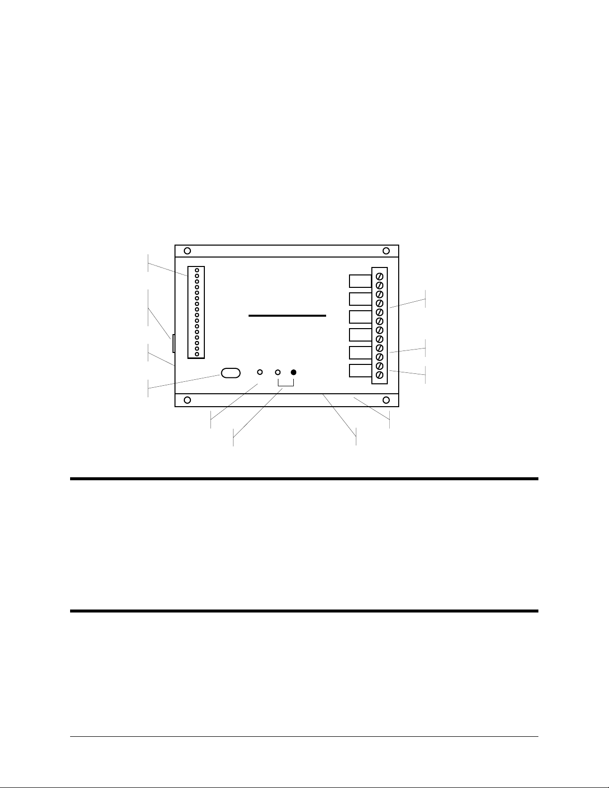
Input Connector
RS-232 Serial
Portfor PC or
Satellite Tranceiver
Phone Connections
I/O Expansion Port
Power Indicator
Input 1
Common
Input 2
Common
Input 3
Common
Input 4
Common
Input 5
Common
Input 6
Common
Input 7
Common
Input 8
Common
Serial Port
Alarm Indicator
Model 570
Remote Monitoring System
Alarm
Power
Output 1
Output 2
Output 3
Output 4
Batt Out
Batt In
+12V DC
Common
AC Power Inlet
Switched AC Outlet
Output Connector
Battery Disconnect
DC Output
A “home” for your Messenger 570
Your new Messenger 570 should be located in a convenient location close to the conditions being monitored - in a
warehouse, basement, utility closet or other work area, mounted on a wall, or mounted inside an equipment cabinet.
When mounted in an optional NEMA-4X weatherproof enclosure, the Messenger 570 can be used in damp or dusty
environments or placed outdoors.
If the outputs of the Messenger 570 are used to switch voltages in excess of 30 volts, the unit must be mounted in an
approved electrical equipment enclosure.
Connecting a Phone Line
The Messenger 570 is designed to work on most public phone systems found throughout the world. It will also work
on most office PBX phone systems. With optional equipment, it will also work on cellular phone systems and with
low-orbiting satellites.
www.remotepossibilities.com
Page 7

2
Standard Phone Lines
For your convenience, the Messenger 570 has a dual phone jack. Plug a telephone line into one of the
Messenger 570’s phone jacks. You can attach a standard telephone into the other jack. It is recommended that
you use this standard telephone to check the phone line for dial tone and the ability to make incoming and
outgoing phone calls.
Cellular Phones
The Messenger 570 will also work with North American analog cellular phones equipped with a dial-tone
adapter. Support for GSM and PCS cellular phones is planned for the future. Contact technical support for
details.
Low-Orbiting Satellites
The Messenger 570 works with an optional satellite transceiver capable of providing cost-effective
communication from virtually any location on Earth. Contact technical support for details.
Connecting a Power Source
The Messenger 570 is factory configured to operate on 110 VAC 50/60 Hz OR 220 VAC 50/60 Hz. It can also
operate from 12 VDC.
AC Operation
Plug the Messenger 570’s power cord into a properly grounded (three-wire) electrical outlet. The power
required by the Messenger 570 is 20 watts plus the wattage of the load (if any) attached to the “AC Switched
Output” connector.
DC Operation
Connect the positive lead of a 9 to 15 VDC source to the “DC IN” terminal and connect the negative lead to the
“Common” terminal.
IMPORTANT: When using DC power, the Messenger 570’s AC power cord MUST be disconnected AND its
backup battery MUST be disabled by removing the jumper from between the “BATT OUT” and “DC IN”
terminals.
Solar Operation
The Messenger 570 can be powered by a properly sized solar panel. Contact technical support for details.
Backup Battery
The Messenger 570 system has an internal rechargeable battery that maintains full operation in the event of a power
outage. This battery must be enabled when the unit is put into service and disabled when taken out of service. All
information programmed into the Messenger 570 system will be retained whether or not the battery is connected to
the system.
NOTE: An auxiliary DC power output on the Messenger 570 system can be used to power external sensors and
accessories. It provides 12 volts DC (nominal) at up to 200 mA. This power is taken from the Messenger 570
system’s backup battery and will provide uninterruptible power, even during a power outage.
Dancer Communications, Inc.
Page 8

Enabling the Backup Battery
Attach the shorting clip (included with the unit) between the “BATT OUT” and “DC IN” terminals. If the
shorting clip is lost, a short length of wire can be used. Once enabled, the battery will require up to 24 hours to
fully charge.
Disabling the Backup Battery
To disable the backup battery, remove the shorting clip from between the “BATT OUT” and “DC IN”
terminals.
Testing the Backup Battery
When operating from AC power, the power light on the front panel of the Messenger 570 system is green.
When operating from battery, the power light is red.
Test the battery at least once per year by removing the Messenger 570’s AC power source for 10 to 15 minutes
and verifying that the power light changes to red and that the unit responds to an incoming phone call.
Attaching the Inputs
3
The Messenger 570 system supports eight universal inputs that can accept a variety of input types. Input expansion
modules are available to increase the monitoring capability of the Messenger 570 to 32 inputs (see Input Expansion
Modules).
Inputs 1 through 4 are factory pre-configured to accept 4-20 mA signals while inputs 5 through 8 are factory pre-
configured to accept dry-contact signals. It is easy to re-configure an input to accept 4-20 mA, 0-5 VDC,
thermistor, logic-level, dry-contact or other signal types in any combination.
DIP Switch Settings
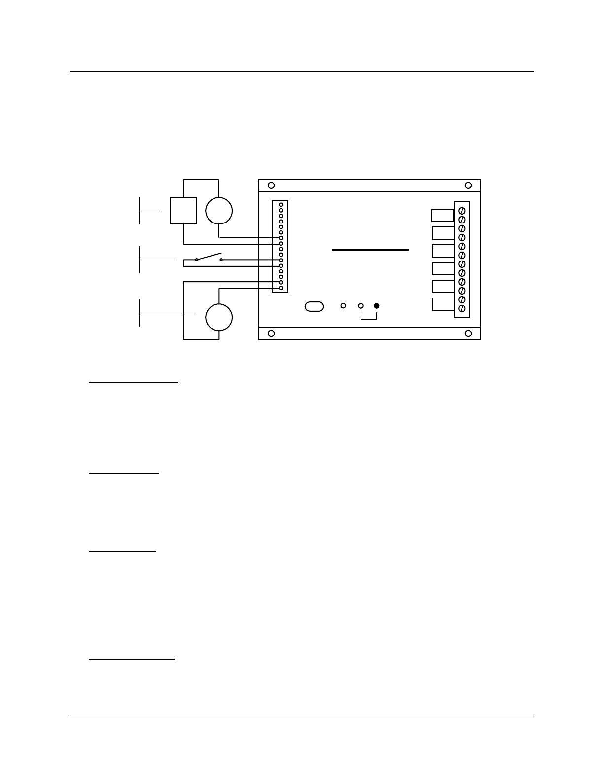
Removing the input connector reveals two banks of DIP switches as illustrated in the figure below. Each bank
has eight switches labeled 1 through 8 corresponding to inputs 1 through 8. The upper bank controls 200-ohm
shunt resistors (required for current monitoring applications) while the bottom bank controls pull-up resistors
(required for temperature monitoring and dry-contact applications.
12345678 12345678
Shunt Resistors
Pull-Up Resistors
OFF ON
Input 1
Common
Input 2
Common
Input 3
Common
Input 4
Common
Input 5
Common
Input 6
Common
Input 7
Common
Input 8
Common
www.remotepossibilities.com
Page 9
4
Input Wiring
Inputs should be wired with 14 to 20 gauge wire. Twisted pair cable is recommended for runs in excess of 20
feet. Input devices requiring 12 VDC can be powered from the Messenger 570’s 12 VDC auxiliary output
terminal.
When wiring the inputs, keep in mind that they share a common ground and that the input signals must not
exceed 5 VDC or 25 mA.
++
4-20 mA
Sensor
Dry
Contact
Temp
Sensor
24 VDC
Supply
4-20 mA
Sensor
Temp.
Sensor
-
-
Input 1
Common
Input 2
Common
Input 3
Common
Input 4
Common
Input 5
Common
Input 6
Common
Input 7
Common
Input 8
Common
Model 570
Remote Monitoring System
Serial Port
Power
Alarm
Output 1
Output 2
Output 3
Output 4
Batt Out
Batt In
+12V DC
Common
Temperature Sensor
Flip to OFF the shunt resistor DIP switch for the input you want to modify and flip to ON the pull-up resistor
DIP switch.
Attach the temperature sensor to the input screw terminals (contact technical support for a list of compatible
thermistor temperature sensors). Use the INP S command to set the scaling and alarm parameters (refer to the
Command Reference section).
0-5 VDC Sensor
Flip to OFF the shunt resistor DIP switch for the input you want to modify and flip to OFF the pull-up resistor
DIP switch.
Attach the 0-5 VDC sensor to the input screw terminals. Use the INP S command to set the scaling and alarm
parameters (refer to the Command Reference section).
4-20 mA Sensor
Flip to ON the shunt resistor DIP switch for the input you want to modify and flip to OFF the pull-up resistor
DIP switch.
Attach your 4-20 mA sensor to the input screw terminals. Keep in mind that the Messenger 570’s internal shunt
resistor is referenced to common and that no other device in the loop can be referenced to ground. If it is
impossible to isolate the other devices in the loop, you can use a signal isolator or an input expansion module.
Use the INP S command to set the scaling and alarm parameters (refer to the Command Reference section).
Dry Contact Switch
Flip to OFF the shunt resistor DIP switch for the input you want to modify and flip to ON the pull-up resistor
DIP switch.
Dancer Communications, Inc.
Page 10

Attach your dry contact sensor to the input screw terminals. Use the INP S command to configure the input for
a dry-contact sensor (refer to the Command Reference section).
TTL Logic
Flip to OFF the shunt resistor DIP switch for the input you want to modify and flip to OFF the pull-up resistor
DIP switch.
Attach the TTL sensor to the input screw terminals. Use the INP S command to configure the input for a dry-
contact sensor (refer to the Command Reference section).
Open Collector
Flip to OFF the shunt resistor DIP switch for the input you want to modify and flip to ON the pull-up resistor
DIP switch.
Attach the open-collector sensor to the input screw terminals. Use the INP S command to configure the input
for a dry-contact sensor (refer to the Command Reference section).
110/220 VAC
Caution: An interposing relay MUST be used to monitor 110/220 VAC signals.
Flip to OFF the shunt resistor DIP switch for the input you want to modify and flip to ON the pull-up resistor
DIP switch.
5
Wire the 110/220 VAC signal to the coil of a suitably rated relay. Wire the relay contacts to the input screw
terminals. Use the INP S command to configure the input for a dry-contact sensor (refer to the Command
Reference section).
Other
To connect a thermocouple, millivolt or other type sensor to the Messenger 570, use an appropriate signal
conditioner. Contact technical support for assistance.
Input Expansion Modules
Optional input expansion modules are available to expand the Messenger 570’s input monitoring capability to 32
inputs.
Each input expansion module accepts up to eight inputs and connects to the Messenger 570 via twisted pair cable.
Each module can be located up to 500 feet away from the Messenger 570.
Contact technical support for additional information.
Connecting the Outputs
The Messenger 570 has four outputs that can be controlled remotely or automatically in response to alarm
conditions or input parameters. The control capabilities of these outputs are described in the “Control” section of
this manual.
Output Relays
Each of the four outputs is capable of switching 5 amp loads. Note: When switching voltages in excess of 30
volts, the Messenger 570 must be placed in an approved enclosure.
www.remotepossibilities.com
Page 11

6
Switched AC Outlet
You can also plug equipment (seven amp maximum load) into the “Switched AC” power outlet located on the
side of the unit (110 VAC units only). This switched outlet works in unison with the output 1 relay on the front
panel.
Dancer Communications, Inc.
Page 12

Communications
This section describes the procedure for establishing communication with a
Messenger 570 system. It includes details on how to use the RS-232 port for
local or satellite communication, a phone line for data, voice, pager and fax
communication, and how to put data into the web.
Using a Phone Line
Data, voice, pager or fax? It’s your decision!
The Messenger 570 system can communicate over a standard phone line with a computer, pager, or facsimile
machine. It also offers a powerful, easy-to-use voice mode for ready-access to information from your equipment
anytime, from any standard telephone.
7
The data mode will allow you to review inputs, set up and reconfigure any Messenger 570 system from a remote
location, retrieve stored information, and perform diagnostics from your PC.
The voice mode offers the convenience of inquiry into condition status from any standard telephone, and provides a
high-quality, clear, consistent voice without the need for set up, programming, or recording.
The Messenger 570 can also be programmed to call a facsimile machine at predetermined times and deliver a
concise status report.
IMPORTANT
℡
Voice Mode
℡
The Messenger 570 will respond to your call by generating a "bong" sound, followed by a few
seconds of silence. If you press the # key on your touch-tone phone during the time of silence, the
system will immediately switch to voice mode. Otherwise, the system will begin to generate a
carrier tone − indicating that the system is attempting to communicate with a data terminal. The
tone will eventually stop after a few seconds and the Messenger 570 will again switch to voice
mode and speak in a synthesized voice:
“Hello, this is telephone number five, five, five, one, two, one, two. Enter security code.”
Enter your eight-digit security code on the touch-tone keypad (initially set at the factory to “1, 1, 1, 1,
1, 1, 1, 1). You do not have to press # after the eight digits are entered. The Messenger 570 system will
respond “OK.”
Information intended exclusively for voice-mode users is
highlighted in this guide by a telephone icon and use of this
different type face
www.remotepossibilities.com
Page 13

8
The voice mode of the Messenger 570 system utilizes a built-in voice enunciator that responds to
commands entered from any standard push-button tone-dialing telephone. You enter command codes
from the telephone keypad and response messages are spoken in English.
Voice Mode commands consist of a three-letter code followed by either the # or * key. The following
commands are available in the Voice Mode:
ALM# = Alarm acknowledge
BYE# = Terminate on-line session
INP# = Input report
OUT# = Output report
TIM# = System time report
VOX# = Custom Voice Phrase Report
For example, typing INP# initiates an INPut report:
INP
GHI4MNO6PQR
7
To end a voice mode session, simply type BYE#.
#
Modem Mode
You can communicate with the Messenger 570 system using a PC with a modem and any popular
communications program having terminal emulation capability. One such communications program is
“Hyperterminal”, a program that is included free with the Microsoft Windows 95, 98, 2000 & NT operating
systems.
Since HyperTerminal is used throughout this manual to illustrate data mode operation, detailed instructions on
its use are included in this section.
Defining a HyperTerminal Connection
To use HyperTerminal, you must first define a few parameters including the phone number of the Messenger
570. To start HyperTerminal, click Start, and then click Programs, Accessories and Hyperterminal. Look for
an icon labeled HyperTerminal or Hypertrm.exe and click on it.
In the Connect Description box, type a name for the connection, choose an icon, then click OK.
In the Connect To box, enter the country/region, area code and phone number of the unit to be called and
choose your computer's modem from the Connect Using list (Note: if your modem is not listed in the Connect
Using list, it may not be installed properly). Click OK.
Click the Dialing Properties button to view information about the location of your computer. You may not
have to make any changes to this box, but make sure the information is correct. If your modem is attached to an
office phone system, you may need to enter a code (such as “9”) to access an outside line. Verify that the
Number to be dialed in the lower left corner of the box appears exactly as it would if you were to dial the
Messenger 570 from your telephone. It must not include any extraneous numbers. Click OK.
In the Connect box, click Cancel. It is now time to save your settings and exit the program. On the
HyperTerminal menu bar, select File, Save and then File, Exit.
Dancer Communications, Inc.
Page 14

Establishing Communication
Once you’ve defined a connection to your Messenger 570, establishing communications with it is as simple as
clicking on an icon.
Start HyperTerminal by clicking Start, Programs, Accessories and Hyperterminal. Look for the Messenger
570 connection that you've created and click on it.
When HyperTerminal starts, you will see the connection information in the Connect box. Click Dial. You may
hear dialing tones or pulses followed by a “ring” sound, followed by modem tones.
When the Messenger 570 answers, it will prompt you to enter a security code. You must enter a valid security
code within 30 seconds or the Messenger 570 will terminate the connection. If you don’t know the security
code, try the factory default security code, “11111111” (eight ones) followed by Enter.
Once you have gained access, you can enter commands and the Messenger 570 will respond. If you press Enter
at the command prompt, you’ll get a complete listing of commands. The most common commands are INP R
(input status report), ALM R (alarm report) and SEC R (security report).
If HyperTerminal fails to connect, re-check your settings (especially Dialing Properties settings) and try again.
Once a connection is established, the Connect box will close and the main HyperTerminal screen will become
active.
In the following sections of this manual are step-by-step procedur es th at will help you prepare the Messenger
570 system to work for you - describing how to designate individuals you want to receive alarm messages, set
low and high alarm set-points, etc.
9
The commands to access the system are simple three-letter codes (e.g. INP = input, ALM = alarm, PHO =
telephone), generally followed by a fourth letter (e.g. R = report, S = set). The system will automatically insert a
blank space between the third and fourth characters.
If an incorrect command is entered, you will receive an “Invalid Command” message.
You may enter a command whenever the “COMMAND>” prompt is displayed.
Fax Mode
The Messenger 570 system can send alarm reports directly to a fax machine. Input status reports can also be
sent to a fax machine on a scheduled basis.
Internet Access
An optional internet service is available that will generate detailed daily repor ts b ased on information collected by
your Messenger 570 and post those reports to a website. Contact customer service for additional information.
Using the RS-232 Port
Attach a “straight-through” serial cable from your PC’s serial port to the RS-232 port on the side panel of the
Messenger 570 system (next to the phone connector).
Follow the procedure outlined in “Modem Mode” (above) to define a HyperTerminal connection, substituting the
appropriate COM port for the modem in the Connect Using list then click Co nfigure and enter the following
settings:
Bits per second: 38400
Parity: none
Stop bits: 1
Flow control: Hardware.
www.remotepossibilities.com
Page 15

10
Commissioning Checklist
The commissioning process tailors the Messenger 570 system to your unique
remote monitoring application. This section outlines the minimal commissioning
tasks required for many applications. Complete details relating to the commands
mentioned in this section are discussed in further detail in the COMMAND
REFERENCE section later in this manual.
IMPORTANT: The Messenger 570 remote monitoring system has many time and
money-saving capabilities that can only be realized after having a thorough
working knowledge of all of the commands described in the COMMAND
REFERENCE section in this manual.
Identify the System
The Messenger 570 has several programmable fields to help identify it in both voice and data modes. These
fields include “site name” and “code number” (for data mode identification) and “unit phone number” (for
voice mode identification).
The information that you enter in these fields will not affect the operation of th e unit but will help you manage
information from your remote sites.
Use the SEC S command to enter system identification information.
Configure the Inputs
The Messenger 570 accepts a variety of different input types.
Use the INP S command to instruct the Messenger 570 as to how to interpret and report this input data.
Configure the Data Logger
The Messenger 570’s data logger can be configured to take periodic “snapshots” of designated inputs and/or
record system events and alarm conditions.
Use the INP S command to designate the inputs to be recorded and the LOG S command to set logging
parameters.
Dancer Communications, Inc.
Page 16

Configuring the Alarm Dialer
The Messenger 570 system continually monitors all inputs for alarm set-points that have been violated. If a set-
point has been exceeded for a designated period of response time, the Messenger 570 system recognizes this as
the existence of an alarm condition.
It will send the message to up to eight designated telephone numbers anywhere on or off site and at any time. If
the calls are unanswered, the Messenger 570 system will wait a pre-set length of time and perform the complete
dial-out sequence again.
The alarm dial-out sequence will continue − even if the alarm condition has cleared − until the alarm has been
externally acknowledged.
To fully configure the alarm dialer, use the INP S command to set the alarm set-points and the PHO O
command to program the dialing directory.
11
www.remotepossibilities.com
Page 17

12
Operation
Reports
The Messenger 570 generates a variety of concise text reports. Each report is updated just prior to generation and is
time-stamped. An auto-report feature, when enabled, produces an input report at the beginning of each
communications session without the need to enter a pass code. Reports can be accessed by any security level.
Input Report
To get a real-time report of the present condition of the eight inputs, including any that may have exceeded an
alarm set-point, type INP R at the command prompt.
Analog inputs will provide LO, HI, and OK status; discrete will provide AL and OK indicators.
COMMAND >INP R
INPUT STATUS REPORT
===== ====== ======
Outside Air OK -82 F
Input #2 OK -66 F
Input #3 OK -83 F
Input #4 OK -85 F
Input #5 OK -85 F
Input #6 OK -85 F
Input #7 OK -85 F
Input #8 OK -85 F
Time: 08/03/96 11:12:36
Output Report
To get a report of the present condition of the four outputs, type OUT R at the command prompt.
COMMAND>OUT R
OUTPUT STATUS REPORT
====== ====== ======
Heater Manual OFF
Output #2 Manual ON
Output #3 Manual ON
Output #4 Manual ON
Time: 08/03/96 11:13:11
COMMAND>
Dancer Communications, Inc.
Page 18

Alarm Report
To get a report of all alarms, including those that have not yet been acknowledged, type ALM R at the
command prompt.
COMMAND>ALM R
ACTIVE ACKNOWLEDGED ALARMS
====== ============ ======
None
UNACKNOWLEDGED ALARMS
============== ======
None
Alarm report. The Messenger 570 system will report all alarms and give you the option to acknowledge any
unacknowledged alarms.
Phone Directory Report
To get a report of the designated dial-out phone names and numbers, type PHO R at the command prompt.
13
COMMAND>PHO R
PHONE NUMBER REPORT
===== ====== ======
1 - Phone #1 No Number
2 - Phone #2 No Number
3 - Phone #3 No Number
4 - Phone #4 No Number
5 - Phone #5 No Number
6 - Phone #6 No Number
7 - Phone #7 No Number
8 - Phone #8 No Number
Security Report
To get a report of various system counters and timers, type SEC R at the command prompt.
Note: These counters and timers are non-volatile and will be retained even if all power is removed from the
Messenger 570 system.
COMMAND>SEC R
SECURITY REPORT
======== ======
Total Alarms: 0
Access Denials: 2
On-line Sessions: 11
Service Outages: 14
System Hours: 8.8
www.remotepossibilities.com
Page 19

14
Alarm Handling
The Messenger 570 system constantly monitors all inputs to determine if alarm set-points have been violated. If a
set-point has been violated for a specified amount of response time, an alarm condition exists.
This alarm condition will continue until the input has returned to normal and has been externally acknowledged.
When an alarm occurs and the response time has expired, the Messenger 570 system will begin its dial-out
sequence. The Messenger 570 system can deliver an alarm in voice, fax or data mode.
The Messenger 570 system will dial each number in succession. If the alarm is not acknowledged, the Messenger
570 system will wait a specified alarm dial-out interval and then start another dial-out sequence with the same alarm
message.
Alarms can be acknowledged in either data or voice mode.
There are two classes of alarms -
Active acknowledged alarms: The input continues to violate an alarm set-point but an operator has acknowledged
the condition. The Messenger 570 system continues to recognize the alarm condition but will not attempt to make an
outgoing phone call.
Unacknowledged alarms: Any alarms, which have not been acknowledged. An unacknowledged alarm initiates an
alarm dial-out sequence.
Alarm Dial-Out Reminder
An optional feature of the Messenger 570 system will enable the dial-out sequence even after an alarm has been
acknowledged.
When an alarm occurs, the Messenger 570 system will dial out to all phone numbers in its phone number list
once or until it is acknowledged. It will then wait the dial-out interval, as specified in the ALM S menu.
If the re-dial after acknowledgment (in ALM S) is enabled, the Messenger 570 system will dial out again if
there are any unacknowledged or acknowledged alarms present.
If disabled, it will re-dial only if there are unacknowledged alarms. When re-dialing, the system will dial every
number in the phone number list or until it is acknowledged.
Responding to an Alarm Message - Voice Mode
℡
The Messenger 570 system will call the preprogrammed numbers when an alarm condition is
recognized. When the phone is answered, the Messenger 570 system will repeat the alarm message
up to six times:
“Hello, this is telephone number one two three four five six seven. Alert condition exists.”
Recipients of such calls should press and hold any keypad button for one to two seconds. The Messenger 570
system will respond with the following message:
“OK. Enter security code.”
Dancer Communications, Inc.
Page 20

When a correct security code has been entered, the Messenger 570 System will acknowledge it, saying, “Yes.”
You can now enter INP R to learn the cause of the input alarm condition and enter ALM# to acknowledge
receipt of the alarm message.
The alarm can be acknowledged in either data or voice mode.
15
℡
To acknowledge an alarm and prevent the Messenger 570 system from dialing out again until
new alarm conditions exist, type ALM#.
Responding to an Alarm Message - Data Mode (local)
For local response, an indicator on the front panel of the Messenger 570 system will flash if there are any
unacknowledged alarms. An ALARM CANCEL switch enables alarms to be canceled from the front panel.
The indicator will remain on continuously if there are acknowledged alarms.
www.remotepossibilities.com
Page 21

16
Control
The Messenger 570 includes a straightforward output controller that enables you
to activate or reset equipment remotely on demand or automatically in response
to input set-points or alarm conditions.
Output Control Modes
The output controller has several modes of operation that can be grouped into three categories: Manual, Automatic
and Alarm. In manual mode, an output is controlled by commands issued by the user. In automatic mode, an output
is controlled by “on” and “off” set-points on a designated input channel. In alarm mode, an output is controlled by
the alarm status of the Messenger 570. You can mix or match control mode settings among the four output channels.
The output control mode settings can be found in the OUT S menu.
AVAILABLE CHOICES
-----------------
1 = Manual
2 = Automatic
3 = Automatic Day
4 = Automatic Night
5 = Close on Present Alarms
6 = Open on Present Alarms
7 = Close on Unacknowledged Alarms
Manual
Manual control permits an operator to remotely control the on/off state of the four output relays.
Use the OUT O command and select the channel you want to control then use the spacebar to manually toggle
the output “on” or “off”.
℡
The on/off state of the output is controlled by the operator with the On1# and On0#
commands. Entering On1# turns output “n” ON and On0# turns output “n” OFF, where “n” is the
desired output number (1-4).
EXAMPLE: To turn output three OFF, press “0”, “3”, “0”, “#” on the phone keypad. To turn output
three ON, press “0”, “3”, “1”, “#” on the phone keypad.
Output
Output
MNO
6
DEF
3
OPER
0
#
MNO
#3 Off
Dancer Communications, Inc.
6
DEF
3
#3 On
1
#
Page 22

Automatic
There are three automatic modes of operation, differing only with respect to the time-of-day in which the
automatic control is active.
Automatic
The output will automatically turn ON or OFF as determined by the Output OFF and Output ON set-points on
its corresponding input. Use the INP S command to set or change the control set-points.
Automatic Day
Identical to AUTOMATIC, except that control only occurs during daytime hours. The output is off during
nighttime hours.
Use the INP S command to set or change the control set-points and the DAY S to set or change START OF
DAY and END OF DAY.
Automatic Night
Identical to AUTOMATIC, except that the output will be OFF during daytime hours.
Alarm
When using one of the alarm tracking modes to control an output, you must enter an alarm mask for that output.
The alarm mask indicates which input’s alarm conditions should be used to control the output. The alarm mask
is a two character hexadecimal number representing an eight bit binary mask. The least significant bit of the
mask correlates to input #1, the most significant bit of the mask correlates to input #8. If a bit in the mask is set
to 0, alarms on the correlating input will not control the output. Conversely, if a bit is set to 1, an alarm on the
correlating input will control the output.
17
As an example, if you want output #1 to be controlled by alarms on input channels 1 through 4, but ignore
alarms on channels 5 through 8, you would use 0F (equivalent to binary 00001111) as the alarm mask.
Close on Present Alarms
The output will go on (close) when an alarm condition presently exists on any of the inputs designated by the
alarm mask. A present alarm is considered to be active when an input alarm set point is exceeded for longer
than the input’s response time.
Open on Present Alarms
The output will go off (open) when an alarm condition presently exists on any of the inputs designated by the
alarm mask. A present alarm is considered to be active when an input alarm set point is exceeded for longer
than the input’s response time.
Close on Unacknowledged Alarms
The output will go on (close) when an alarm condition exists on any of the inputs designated by the alarm
mask, and stay on even if the alarm condition goes away. It will turn off (open) when the alarm condition is
acknowledged.
www.remotepossibilities.com
Page 23

18
Data Logging/Trending
It is often desirable to track conditions (such as tank level or ambient air
temperature) over extended periods of time. The Messenger 570 system
provides this ability by recording and maintaining a history of input and output
conditions - information that provides valuable insight into the operation of a
process, equipment, or facility. This information can be readily accessed through
the RS-232 port or via telephone.
The information can be recorded at regular time intervals or in response to an
alarm condition, or both.
Set-up and Operation
Log Set-Up (LOG S).
To enable or disable logging functions and to set up log time, type LOG S.
COMMAND>LOG S
DATA LOG SETUP
==== === =====
1 = Periodic Log Enable Disabled
2 = Periodic Log Rate 00:01:00.0 (hh:mm:ss)
3 = High Resolution Log Enabled
4 = Clear Periodic Log
0 = Previous Menu
Choose a Number>
Periodic Recording
To enable or disable the periodic recording of all input and output conditions, type LOG S and choose #1.
When turned on, the Messenger 570 system will automatically log all input and output conditions at regular
intervals of time.
Log Time
To set the data-logging interval, type LOG S and choose #2 when periodic recording is on (see above).
Intervals can be set to any time, 00:00:05 to 99:59:59.
High Resolution Log
When the high-resolution log is enabled then two bytes will be stored for each input selected for logging.
When the high-resolution log is disabled, only one byte per selected input is logged.
Dancer Communications, Inc.
Page 24

Log Operations (LOG O)
Whenever a system or log event occurs, the Messenger 570 system will write to memory a time-stamped record
of parameters. System events such as system resets, alarm detection, alarm acknowledgments, alarm dial outs,
etc. are automatically logged. Log events are logged at the periodic log rate if periodic logging is enabled.
(See LOG S.) When the data log becomes full, the overload data will wrap around and erase previous data
without any alarm or warning. It is up to the operator to set the log-time interval so that it will be possible to
download the logged data before the data logger becomes full.
Data Extraction and Analysis
Data from the Messenger 570 system can be downloaded in a readable format or in a file format compatible
with most spreadsheet and data analysis programs. Select the desired format with the LOG O command.
COMMAND>LOG O
DATALOG OPERATIONS
======= ==========
1 = Display uncompressed periodic log in ASCII.
2 = Download uncompressed periodic log using X-modem.
3 = Download compressed periodic log using X-modem.
5 = Display data log configuration.
0 = Previous Menu
19
Choose a Number>
Uncompressed Log Format
All uncompressed records contain comma-delimited ASCII fields. The following format is used for all
uncompressed records received from the data logger.
REC,MM/DD/YY hh:mm:ss.s, Reserved, XIN, A1, A2, A3, A4, A5, A6, A7, A8, O1, O2, O3, O4 [,O5, O6, O7, O8]*
REC Record type.
MM/DD/YY Month / Date / Year
hh:mm:ss.s Hour: Minute: Second
Reserved Reserved (Old Ack ID field.)
XIN Extended Inputs (a decimal representation)
A1-A8 Analog input 1 through 8. Each input value is in engineering units. Un-logged
inputs are represented by comma-separated null fields.
O1-O8 Digital outputs 1 through N.
* Only th e o utputs that are physically present on a unit will be in the log.
Record Type is a three-character field that describes the nature of the log entry:
ACK Acknowledged alarm
ALM An alarm condition occurred
DOF An alarm dial-out has failed
DOS An alarm dial-out has succeeded
HKR (Hacker) Too many bad passwords entered
LOG A time-initiated record in g
MFL The modem has failed power-up diagnostics
NRM An alarm condition returned to normal
OFF The end of an on-line session
ON The beginning of an on-line session
POW A power failure alarm has occurred
RST Hardware reset
TFL A real-time clock failure has occurred
www.remotepossibilities.com
Page 25

20
X-modem Downloads
The most reliable way to transfer large amounts of data from the Messenger 570 system to a personal computer
is with the XMODEM file transfer protocol. Many communications programs (such as ProComm) support the
XMODEM protocol.
If a data error occurs during a file transfer (due to line noise, for example), XMODEM will detect the error and
correct it.
Once you initiate an XMODEM data transfer, you have 30 seconds to tell your communications program to
start the XMODEM transfer.
Compressed logs
Downloading a compressed log file is also possible. The data compression scheme used in the Messenger 570
system strips out all commas and other punctuation, and converts the data from ASCII decimal to binary. The
result is a data file, which is at least one-fourth its original size and transfers in one-fourth the time of the
original data file. To decompress the data to its original comma-delimited form, use the DOS decompression
utility “D-COMP,” which is included on the companion disk. The program will request the name of the input
file and output file. When the conversion is complete, you will be able to view the data with any text editor or
load the data into a spreadsheet program such as Lotus 1-2-3 or Excel.
Dancer Communications, Inc.
Page 26

21
Voice Recorder
The Messenger 570’s voice enunciator uses a combined lexicon of high-quality
pre-recorded phrases and phrases that you record. The recording process
utilizes the multimedia capabilities of your computer – phrases are recorded on
your PC, then uploaded to the Messenger 570. This process produces superior
results and facilitates the commissioning of multiple units.
Voice Mode Reporting
When generating an input or an output report in voice mode the Messenger 570 system will compare each point’s
label name with a list of phrase names that make up the unit’s vocabulary. If an exact match is found, then the unit
will play the voice file associated with that phrase name. Each unit is preprogrammed with a list of permanent
phrases and voice files. In addition to these permanent phrases, the user h as th e ability to upload custom phrases and
voice files.
Custom Voice Phrases
It is possible for the user to upload 17 different custom voice phases into the Messenger 570 system. Sixteen of
these phrases can be up to 1.11 seconds long each and are used to create custom input and output reports in voice
mode. The 17th voice file can be up to 8.88 seconds long and is used as the sign-on greeting at the beginning of a
voice mode session. Creating these voice files and uploading them is a three-step process.
1)
RECORD: Each voice phrase is recorded as an individual .WAV file on your PC. The .WAV must be in a
PCM format at 22,050 Hz with 16-bit mono samples. Once you have recorded your phrases, you need to
make sure that they are not longer than the maximum time period allowed. (8.88 seconds for the greeting and
1.11 seconds for all other phrases.)
2)
COMPRESS: After you have your phrases recorded, you need to compress them. This is accomplished using
the voice utilities provided by Dancer Communications.
a) Create a directory that contains only your .WAV files.
b) Copy all of the voice utility files into this directory. (COMPALL.BAT, WS22.BAT, and
DBMAINBM.EXE)
c) Run COMPALL.BAT. This will convert each of the .WAV files into compressed .BIN files. A file named
VOXLIST.TXT that contains a list of all of your converted files and their sizes will be created.
3)
UPLOAD: Go online with the Messenger 570 system in data mode (either direct connect or via modem.) and
issue the VOX S command. You will be prompted for:
a) A phrase name. When generating a report in voice mode the Messenger 570 system will compare the
label names in the report to the voice phrase names. Any time a match occurs, the voice file associated
with that phrase will be vocalized.
b) A file size. This is the size of the .BIN file.
c) An X-modem upload of the compressed voice file itself. (The .BIN file).
d) Repeat. Each phrase and file should be uploaded.
www.remotepossibilities.com
Page 27

22
e) To play back your uploaded messages, call the unit in voice mode. After entering your security code, enter
the VOX # command. This will cause the Messenger 570 to vocalize the entire custom voice list.
Once you have completed steps 1 and 2, you can perform step 3 on as many units as desired. If you wish to add or
change a voice file, only that file needs to be uploaded. All of the custom phrases and voice files are stored in non-
volatile memory and are not affected by a power outage. They are, however, erased when performing a flash code
update.
Custom Greeting
The 17th phrase is a custom greeting that is played at the beginning of a voice mode session. This message replaces
the “Hello, this is telephone number ...” that is played as the default greeting. If the 17th phrase name is “Empty,”
then the default greeting is given. Otherwise, the custom message will be played. This message can be up to 8.88
seconds long.
Dancer Communications, Inc.
Page 28

Command Reference
To Messenger 570 remote monitoring system contains many features and
functions that can save you both time and money. An understanding of the
commands described in this section will help you maximize the return on your
remote monitoring investment.
The commands in this reference are listed in alphabetical order.
ALM (Alarm Commands)
23
These commands configure the Messenger 570 system to continually monitors all inputs for alarm conditions. If a
set-point has been exceeded for a designated period of response time, the Messenger 570 system recognizes this as
the existence of an alarm condition.
Help with the ALM command
Type ALM at the command prompt and the Messenger 570 system will return a list of valid alarm commands
and related instructions.
COMMAND>ALM
ALARM FUNCTIONS
===== =========
ALM R Alarm Report
ALM S Set/Check Alarm Settings
Alarm Reports
Type ALM R at the command prompt and the Messenger 570 system will generate an alarm status report.
COMMAND>ALM R
ACTIVE ACKNOWLEDGED ALARMS
====== ============ ======
None
UNACKNOWLEDGED ALARMS
============== ======
None
www.remotepossibilities.com
Page 29

24
Alarm Set-up
Type ALM S at the command prompt and the Messenger 570 system will display a sub-menu of alarm related
parameters that you can alter.
COMMAND>ALM S
ALARM SETUP
===== =====
1 = Local Alarm Siren Enabled
2 = Dial-out Interval 60 min.
3 = Inter Dial Delay 0 min.
4 = Snooze Timer Delay 160 hours
5 = Alarm Dialout Trigger Individual Alarms
0 = Previous Menu
Choose a Number>
Local Alarm Siren
When enabled, the Messenger 570 system's internal beeper will sound whenever an unacknowledged alarm
exists. When disabled, the beeper will never sound.
COMMAND>ALM S
ALARM SETUP
===== =====
1 = Local Alarm Siren Enabled
2 = Dial-out Interval 60 min.
3 = Dial-out Delay 1 min.
0 = Previous Menu
Choose a Number>1
Local Alarm Siren Enabled
Change Present State? [y/n]> No
Dial-out Interval
This parameter specifies the amount of time the Messenger 570 system will wait after attempting to dial
every phone number before it will attempt to dial again.
COMMAND>ALM S
ALARM SETUP
===== =====
1 = Local Alarm Siren Enabled
2 = Dial-out Interval 60 min.
3 = Dial-out Delay 1 min.
0 = Previous Menu
Choose a Number>2
Enter New Dial-out Interval>60
Dancer Communications, Inc.
Page 30

Inter dial Delay
Snooze Timer Delay
Alarm Dial-out Trigger
BYE (End Session)
Type BYE at the command prompt and the Messenger 570 system will terminate the current session.
COMMAND>BYE
COM (Communications Gateway)
The Messenger 570 system provides a data path between its phone line modem and its local RS-232 port, allowing
you to talk “through” the Messenger 570 system to an external computer or system.
Help with the COM command
Type COM at the command prompt and the Messenger 570 system will return a list of valid communications
commands and related instructions.
25
COMMAND>COM
COMMUNICATION FUNCTIONS
============= =========
COM S Set/Check Communication Settings
COM R Enter Gateway Mode (Modem Only)
Open Communications Gateway
Type COM R at the command prompt and the Messenger 570 system will open a communications path between
the modem and its serial port. This path can be used to establish communications with a secondary Messenger
570 system or almost any other device that has an RS-232 port.
When using the communications gateway, make sure that the RS-232 cable connecting the Messenger 570
system and secondary device supports full hardware (RTS/CTS) handshaking. If the secondary device does not
support hardware handshaking, you must make sure that neither device transmits more data than the receiver
can handle.
For example: If you have a Messenger 570 system operating its modem at 33.6 kbps and its RS-232 at 115
kbps you must make sure that the device attached to the RS-232 port does not transmit data at a sustained rate
of 115kbps. Because the Messenger 570 system would be receiving data 3.5 times faster than it can send it, the
receive buffer will fill up quickly. The Messenger 570 can buffer up to 256 incoming and outgoing bytes but
any data received after a buffer has filled up will be lost.
*Note: If you attach a device that continuously generates data to the Messenger 570 RS-232 port, you must
enable the smart gateway option. (See COM S).
www.remotepossibilities.com
Page 31

26
COMMAND>COM R
COMMUNICATIONS GATEWAY
============== =======
1 = RS-232 Port
2 = RS-485 Port
0 = Previous Menu
Choose a Number>1
GATEWAY MODE
======= ====
Connecting modem to RS-232 port.
A Control-D after 2 seconds of silence
will close gateway.
Communications Gateway Set-up
Type COM S at the command prompt and the Messenger 570 system will display a sub-menu of related
parameters that you can alter.
COMMAND>COM S
COMMUNICATIONS SETUP
============== =====
1 = Local RS-232 Baud Rate: 38.4k
2 = Smart Gateway Mode: Disabled
3 = Gateway Echo: Disabled
0 = Previous Menu
Local RS-232 Baud Rate
The baud rate can range from 4.8 to 115.6 kbps.
Dancer Communications, Inc.
Page 32

COMMAND>COM S
COMMUNICATIONS SETUP
============== =====
1 = Local RS-232 Baud Rate: 38.4k
2 = Smart Gateway Mode: Disabled
3 = Gateway Echo: Disabled
0 = Previous Menu
Choose a Number>1
Set/Check Baud Rate
========= ==== ====
1 = 4800
2 = 9600
3 = 19.2K
4 = 38.4k
5 = 57.6k
6 = 115.6k
0 = Previous Menu
Choose a Number>
27
Smart Gateway Mode
When "Smart Gateway Mode" is enabled, the Messenger 570 system's serial port will remain inactive until
it sees a "CONTROL A."
COMMAND>COM S
COMMUNICATIONS SETUP
============== =====
1 = Local RS-232 Baud Rate: 38.4k
2 = Smart Gateway Mode: Enabled
3 = Gateway Echo: Disabled
0 = Previous Menu
Choose a Number>2
Smart Gateway Mode: Enabled
Change Present State? [y/n]> Yes
Gateway Echo
When enabled, characters that are received from the modem will be echoed back to the modem as well as
being sent to the serial port.
www.remotepossibilities.com
Page 33

28
COMMAND>COM S
COMMUNICATIONS SETUP
============== =====
1 = Local RS-232 Baud Rate: 38.4k
2 = Smart Gateway Mode: Disabled
3 = Gateway Echo: Disabled
0 = Previous Menu
Choose a Number>3
Gateway Echo: Disabled
Change Present State? [y/n]> Yes
CNT (Pulse Counter)
The Messenger 570 system allows pulse counting on all eight analog inputs. It uses two commands in data mode,
CNT R, to display all eight counters, and CNT O, to clear individual counters.
The maximum transition rate is 100 state transitions/second (50 Hz signal = 50 counts/second) with no two
transitions occurring within less than 10ms of each other. The signal can be a square, saw-tooth, or sine wave, with
a transition being a change from above three volts and below two volts, and vice versa. Total counts are displayed
as decimals.
Help with the CNT command
Type CNT at the command prompt and the Messenger 570 system will return a list of valid counter commands
and related instructions.
COMMAND>CNT
INPUT COUNTER FUNCTIONS
===== ======= =========
CNT R Input Counter Report
CNT O Input Counter Operations
Counter Report
Type CNT R at the command prompt to view the count totals for all of the inputs.
COMMAND>CNT R
INPUT COUNTER REPORT
===== ======= ======
Outside Air 1
Input #2 1204
Input #3 1
Input #4 1
Input #5 1
Input #6 1
Input #7 1
Input #8 1
Dancer Communications, Inc.
Page 34

Clear Counters
Type CNT O at the command prompt to reset any or all of the counts.
COMMAND>CNT O
INPUT COUNTER OPERATIONS
===== ======= ==========
1 = Clear Outside Air 1
2 = Clear Input #2 1204
3 = Clear Input #3 1
4 = Clear Input #4 1
5 = Clear Input #5 1
6 = Clear Input #6 1
7 = Clear Input #7 1
8 = Clear Input #8 1
9 = Clear all input counters
0 = Previous Menu
Choose a Number>
29
CRT S - Critical Condition Setup Menu
COMMAND> CRT S
SET/CHECK CRITICAL INPUT SETTINGS
========= ======== ===== ========
1 = Set/Check Critical Input Channels
2 = Set/Check Critical Condition Threshold
3 = Set/Check Critical Condition Actions
0 = Previous Menu
Choose a Number>1
SET/CHECK CRITICAL INPUT CHANNELS
========= ======== ===== ========
01 = Input #01 Critical 17 = Input #17 Non-critical
02 = Input #02 Critical 18 = Input #18 Non-critical
03 = Input #03 Critical 19 = Input #19 Non-critical
04 = Input #04 Critical 20 = Input #20 Non-critical
05 = Input #05 Non-critical 21 = Input #21 Non-critical
06 = Input #06 Non-critical 22 = Input #22 Non-critical
07 = Input #07 Non-critical 23 = Input #23 Non-critical
08 = Input #08 Non-critical 24 = Input #24 Non-critical
09 = Input #09 Critical 25 = Input #25 Non-critical
10 = Input #10 Critical 26 = Input #26 Non-critical
11 = Input #11 Critical 27 = Input #27 Non-critical
12 = Input #12 Critical 28 = Input #28 Non-critical
13 = Input #13 Non-critical 29 = Input #29 Non-critical
14 = Input #14 Non-critical 30 = Input #30 Non-critical
15 = Input #15 Non-critical 31 = Input #31 Non-critical
16 = Input #16 Non-critical 32 = Input #32 Non-critical
00 = Previous Menu
Choose a Number>1
Input #1 is currently a critical input.
Change present state? [y/n]>n
COMMAND> CRT S
SET/CHECK CRITICAL INPUT SETTINGS
========= ======== ===== ========
1 = Set/Check Critical Input Channels
2 = Set/Check Critical Condition Threshold
3 = Set/Check Critical Condition Actions
www.remotepossibilities.com
Page 35

30
0 = Previous Menu
Choose a Number>2
SET/CHECK CRITICAL CONDITION THRESHOLD
========= ======== ========= =========
The critical condition threshold is used to indicate when
a critical condition exists. When the number of critical
input channels, in the alarm state, meets or exceeds the
critical condition threshold, a critical condition event
is triggered.
Current Value: 4
Change present state? [y/n]>y
Enter new value (1 - n) > 4
COMMAND> CRT S
SET/CHECK CRITICAL INPUT SETTINGS
========= ======== ===== ========
1 = Set/Check Critical Input Channels
2 = Set/Check Critical Condition Threshold
3 = Set/Check Critical Condition Actions
0 = Previous Menu
Choose a Number>3
SET/CHECK CRITICAL CONDITION ACTIONS
========= ======== ========= =======
1 = Freeze Secondary Logger Disabled
0 = Previous Menu
CRT R - Critical Condition Report
COMMAND> CRT R
CRITICAL CONDITION REPORT
======== ========= ======
Critical Condition Status:
No critical condition exists.
[An active critical condition exists.]
[An inactive critical condition exists.]
Critical channels in an active alarm state: 12
Critical condition threshold: 5
Critical Condition Actions Status
Periodic Log: Logging Pre-trigger Data [Post-
trigger data][Frozen]
Diagnostics log: Logging Pre-trigger Data [Post-
trigger data][Frozen]
Dancer Communications, Inc.
Page 36

CRT O - Critical Condition Operations
The Critical Condition Operations menu varies based upon the system's current condition. Any one of three
conditions may exist.
An active critical condition exist: This state is entered when th e number of critical input channels that are
simultaneously in the active alarm state meets or exceeds the critical condition threshold.
An inactive critical condition exists: This state is entered from the active critical condition state after th e
number of critical input channels that are currently in the active alarm state does not meet or exceed the critical
condition threshold.
No critical condition exists: This state is entered only after a user manually resets the critical condition lo gic
using the CRT O command.
COMMAND> CRT O
CRITICAL CONDITION OPERATIONS
======== ========= ==========
No critical condition exists.
There are n critical input channels currently in the
active alarm
state which does not meet or exceed the critical
condition threshold
of n channels.
31
COMMAND> CRT O
CRITICAL CONDITION OPERATIONS
======== ========= ==========
An inactive critical condition exists.
Resetting the critical condition logic will terminate
all active
critical condition actions.
Do you wish reset the critical condition logic?
(y/n)>Yes
OK.
COMMAND> CRT O
CRITICAL CONDITION OPERATIONS
======== ========= ==========
An active critical condition exists.
There are n critical input channels currently in the active alarm
state, meeting or exceeding the critical condition threshold of n
channels. The critical condition logic cannot be reset until the
number of critical input channels in the active alarm state is
reduced or the critical condition threshold is raised.
www.remotepossibilities.com
Page 37

32
DIP
Help with the DIP command
Type DIP at the command prompt and the Messenger 570 system will return a list of valid alarm commands
and related instructions.
COMMAND>DIP
DIP SWITCH SETTING
===== =========
DIP R DIP Switch Report
DIP Switch Report
Type DIP R at the command prompt and the Messenger 570 system will generate a report indicating the
required DIP switch settings for the unit’s current input setup. Note: This report does not indicate the
current DIP switch settings. It only reports how the DIP switches should be set.
COMMAND>DIP R
TOP DIP SWITCH
=== === ======
0 = OFF
1 = OFF
2 = OFF
3 = OFF
4 = ON
5 = ON
6 = ON
7 = ON
BOTTOM DIP SWITCH
====== === ======
0 = ON
1 = ON
2 = ON
3 = ON
4 = OFF
5 = OFF
6 = OFF
7 = OFF
The example above shows what a report would look like if you had inputs 1-4 defined as 4-20 mA sensor
types and input 5-8 as dry contact sensor types.
HLP
Help
Type HLP at the command prompt and the Messenger 570 system will return instructions for entering
commands .
Dancer Communications, Inc.
Page 38

INI S
33
COMMAND>HLP
COMMAND FORMAT
======= ======
3 letter command followed by operand.
Example: INP R (INPut Report)
SPECIAL KEYS
======= ====
^Z or ESC interrupts report.
COMMAND>INI S
Initialization Menu
============== ====
1 = Model Name: ****************
2 = Enhanced Output Menu Disabled
3 = Reset Counters
0 = Previous Menu
Choose a Number>
INP (Input Commands)
Input commands permit you to check the condition of any monitored input and configure the inputs for a variety of
applications. Custom or non-standard sensors can also be accommodated by means of "Look-Up" tables.
Each input has separate alarm and control set points. The control set points can be used to automatically control
output devices (see OUT S).
Help with the INP command
Type INP at the command prompt and the Messenger 570 system will return a list of valid input commands and
related instructions.
COMMAND>INP
INPUT FUNCTIONS
===== =========
INP R Input Status Report
INP S Set/Check Input Settings
INP O Input Filtering Operations
Input Status Report
To get a real-time report of the present condition of the eight inputs, including any that may have exceeded an
alarm set point, type INP R at the command prompt.
Analog inputs will provide LO, HI, and OK status; discrete will provide AL and OK indicators.
www.remotepossibilities.com
Page 39

34
COMMAND>INP R
INPUT STATUS REPORT
===== ====== ======
Input #1 OK -94 F
Input #2 OK -78 F
Input #3 OK -89 F
Input #4 OK -93 F
Input #5 OK -93 F
Input #6 OK -93 F
Input #7 OK -93 F
Input #8 OK -93 F
Time: 08/03/96 05:53:21
Input Operation Parameters
Type INP O at the command prompt to get a sub-menu parameters (applied globally to all inputs) that affect the
sensitivity and responsiveness of the monitored inputs.
COMMAND>INP O
INPUT OPERATIONS
===== ==========
1 = Input Dampening: Enabled
2 = Input Deadband: 1
3 = Rate of change period: 00:00:10 (hh:mm:ss)
0 = Previous Menu
Input Damping
Input damping causes the Messenger 570 to react slowly to a rapidly changing input. For example, if
temperature were being monitored and the temperature probe was moved from an ice bath to a hot water
bath, a damped input would show a gradual change in temperature every 10 to 20 seconds, rather than an
instantaneous change. This option will eliminate many false alarm situations.
COMMAND>INP O
INPUT OPERATIONS
===== ==========
1 = Input Dampening: Enabled
2 = Input Deadband: 1
3 = Rate of change period: 00:00:10 (hh:mm:ss)
0 = Previous Menu
Choose a Number>1
Input Dampening is Enabled
Change Present State? [y/n]> No
Deadband
When set to a value greater than 1, the Messenger 570 system will not report a change in input value until
the change exceeds the deadband.
Dancer Communications, Inc.
Page 40

COMMAND>INP O
INPUT OPERATIONS
===== ==========
1 = Input Dampening: Enabled
2 = Input Deadband: 1
3 = Rate of change period: 00:00:10 (hh:mm:ss)
0 = Previous Menu
Choose a Number>2
Enter New Deadband in ADC counts> 1
Rate-of-Change Period
The rate of change period is the period of time that a Messenger 570 waits in before taking the samples that
are to be used in the rate of change alarm checks. Note: This time period only applies to the rate of change
set point checks. All other set points are checked and acted upon once every 100 ms.
Input Setup Parameters
Type INP S at the command prompt to control the configuration parameters for each input. You will get a list
of all configurable inputs. Select the input you wish to configure and you will get a sub-menu containing
parameters for that input.
35
COMMAND>INP S
SET/CHECK INPUT SETTINGS
========= ===== ========
1 = Input #1 <Label>
2 = Input #2 <Label>
3 = Input #3 <Label>
4 = Input #4 <Label>
5 = Input #5 <Label>
6 = Input #6 <Label>
7 = Input #7 <Label>
8 = Input #8 <Label>
0 = Previous Menu
Choose a Number>1
Input #1
PRESENT SETTINGS
======= ========
01 = Label <Label>
02 = Sensor Type Temperature (°F)
03 = High Alarm Set Point 260
04 = Low Alarm Set Point -94
05 = Response Time 0 Sec.
06 = Output On Set Point 260
07 = Output Off Set Point -94
08 = Calibration Offset 0
09 = Data Logging Enabled
00 = Previous Menu
Choose a Number>
www.remotepossibilities.com
Page 41

36
The Input Setup - Present Settings menu varies depending upon the sensor type and whether or not it is an
extended input. While each sensor type has a unique set of parameters, many of those parameters can be
found in more than one set. A chart of sensor types and parameters is shown below.
Common Parameters
Temperature
Label Sensor
Type
x x x
Data
Logging
°F
Temperature
x x x
°C
Dry Contact x x x
Pulse
x x x
Totalizer
Pulse Rate x x x
Linear x x x
4 to 20 mA x x x
Extended
X X
Input
Alarm Parameters
Temperature
High
Alarm
Setpoint
x x x x
Low
Alarm
Setpoint
Alarm
State
Respons
e Time
°F
Temperature
x x x x
°C
Dry Contact x x
Pulse
x x
Totalizer
Pulse Rate x x x
Linear x x x x
4 to 20 Ma x x x x
Extended
X X X
Input
Rate
Setpoint
Output Control Parameters
Temperature
Output
On
Setpoint
x x
Output
Off
Setpoint
Output
On
State
Output
Off State
°F
Temperature
x x
°C
Dry Contact x x
Pulse
Totalizer
Pulse Rate x x
Linear x x
4 to 20 mA x x
Extended
Dancer Communications, Inc.
Page 42

Input
Span/Scaling Parameters
Top/Botto
m of
Scale
Gain
Calibrati
on
37
Units
Open/Clos
ed
Description
Temperature
x
°F
Temperature
x
°C
Dry Contact x
Pulse
x x
Totalizer
Pulse Rate x x
Linear x x x
4 to 20 mA x x x
Extended
x
Input
Extended Input Specific Parameters
External Input Module
Channel Address
Sensor Output Range
Fault Value
Label
Each of the eight input channels can be given a name. Type INP S and choose from the menu the input you
want to name. A second menu will be given, listing all parameters associated with that input. Choose menu
item #1 Label and enter the label name for the input.
At the enter labeo
www.remotepossibilities.com
Page 43

38
COMMAND>INP S
SET/CHECK INPUT SETTINGS
========= ===== ========
1 = Input #1 <Label>
2 = Input #2 <Label>
3 = Input #3 <Label>
4 = Input #4 <Label>
5 = Input #5 <Label>
6 = Input #6 <Label>
7 = Input #7 <Label>
8 = Input #8 <Label>
0 = Previous Menu
Choose a Number>1
Input #1
PRESENT SETTINGS
======= ========
01 = Label <Label>
02 = Sensor Type Temperature (°F)
03 = High Alarm Set Point 260
04 = Low Alarm Set Point -94
05 = Response Time 0 Sec.
06 = Output On Set Point 260
07 = Output Off Set Point -94
08 = Calibration Offset 0
09 = Data Logging Enabled
00 = Previous Menu
Choose a Number>1
Enter New Label>Outside Air
Sensor Type
Dancer Communications, Inc.
Page 44

COMMAND>INP S
SET/CHECK INPUT SETTINGS
========= ===== ========
1 = Input #1 <Label>
2 = Input #2 <Label>
3 = Input #3 <Label>
4 = Input #4 <Label>
5 = Input #5 <Label>
6 = Input #6 <Label>
7 = Input #7 <Label>
8 = Input #8 <Label>
0 = Previous Menu
Choose a Number>1
Input #1
PRESENT SETTINGS
======= ========
01 = Label <Label>
02 = Sensor Type Temperature (°F)
03 = High Alarm Set Point 260
04 = Low Alarm Set Point -94
05 = Response Time 0 Sec.
06 = Output On Set Point 260
07 = Output Off Set Point -94
08 = Calibration Offset 0
09 = Data Logging Enabled
00 = Previous Menu
39
Choose a Number>2
AVAILABLE CHOICES
----------------1 = Temperature (°F)
2 = Temperature (°C)
3 = Dry Contact
4 = Pulse Totalizer
5 = Pulse Rate
6 = Linear
7 = Reserved-Custom A
8 = Reserved-Custom B
9 = 4 to 20mA
0 = Previous Menu
Choose a Number> 6
Alarm Set-Points
Each of the input channels can be given alarm set points.
Inputs configured with a temperature, pulse rate, custom, linear, or 4 to 20 mA sensor type can be given
high and low alarm set points. Inputs configured as pulse totalizers have only a high alarm set point.
Inputs configured as Dry contacts have only one alarm state.
If the input value falls below the low alarm set point or above the high alarm set point for a defined period
of time, the Messenger 570 system will recognize an alarm condition. In the case of a dry contact, if the
input state equals the configured alarm state then an alarm condition is triggered.
www.remotepossibilities.com
Page 45

40
To enter a low alarm or high alarm limit, type INP S. Each of the input items should be given a low set
point, below which the Messenger 570 system will be activated and send alarm messages, and a high set
point, conversely above which the system will be activated.
When adding data at the “Enter New Value” prompt, please note that the range depends on the input type
as well as the bottom and top of scale definitions.
To disable the low alarm, set it equal to the bottom of scale parameter. To disable the high alarm, set it
equal to the top of scale parameter.
COMMAND>INP S
SET/CHECK INPUT SETTINGS
========= ===== ========
1 = Input #1 Outside Air
2 = Input #2 <Label>
3 = Input #3 <Label>
4 = Input #4 <Label>
5 = Input #5 <Label>
6 = Input #6 <Label>
7 = Input #7 <Label>
8 = Input #8 <Label>
0 = Previous Menu
Choose a Number>1
Input #1
PRESENT SETTINGS
======= ========
01 = Label Outside Air
02 = Sensor Type Temperature (°F)
03 = High Alarm Set Point 260
04 = Low Alarm Set Point -94
05 = Response Time 0 Sec.
06 = Rate Alarming Disabled
07 = Output On Set Point 260
08 = Output Off Set Point -94
09 = Calibration Offset 0
10 = Data Logging Enabled
00 = Previous Menu
Choose a Number>3
Enter New High Alarm>25
Response Time
Each of the input channels can be given a response time. This time determines how long an alarm condition
must exist before it is recognized as an alarm. Type INP S and choose the input you want to modify from
the menu. A second menu will be given listing all parameters associated with that input. Choose Response
Time and enter the desired response time. The response time can range from 0 second to 10,000 seconds
(about one week). The response time only applies to alarm set points.
Dancer Communications, Inc.
Page 46

COMMAND>INP S
SET/CHECK INPUT SETTINGS
========= ===== ========
1 = Input #1 Outside Air
2 = Input #2 <Label>
3 = Input #3 <Label>
4 = Input #4 <Label>
5 = Input #5 <Label>
6 = Input #6 <Label>
7 = Input #7 <Label>
8 = Input #8 <Label>
0 = Previous Menu
Choose a Number>1
Input #1
PRESENT SETTINGS
======= ========
01 = Label Outside Air
02 = Sensor Type Temperature (°F)
03 = High Alarm Set Point 260
04 = Low Alarm Set Point -94
05 = Response Time 10000 Sec.
06 = Rate Alarming Disabled
07 = Output On Set Point 260
08 = Output Off Set Point -94
09 = Calibration Offset 0
10 = Data Logging Enabled
00 = Previous Menu
41
Choose a Number>5
Enter New Response Time>120
Rate Alarm Set-Points
The Messenger 570 system is capable of detecting and alarming on various input rate of change conditions.
The conditions detected vary depending upon the input type.
For temperature, linear, and 4-20 mA, sensor types a single rate of change set point may be entered. This
•
set point may be positive or negative and is in addition to the normal high and low alarm set points. Each
of these set points are entered in engineering units. Unlike the high and low set points which are
continuously scanned 10 times/second, the rate at which these inputs are scanned for rate-of-change
condition is based on the rate of change scan period. (See INP O.)
The rate of change scan period is a global, user-programmable time period, from 1 second to 24 hours.
•
Being global, this period applies to all temperature, linear, and 4-20 ma, sensor types. Upon system reset,
each of these inputs will have their current values stored in memory. After the rate-of-change time period
has elapsed, the input values are read and compared to the previously stored value. If the difference of
these two values exceeds the rate-of-change set point, then an alarm is triggered. The alarm response time
does not apply to the rate-of-change set points. Only the readings taken at the rate-of-change interval are
compared to the rate-of-change set point. Any activity occurring between the rate-of-change in terval is
ignored.
For pulse count rate sensor types, the input is always represented by a positive hourly rate. This hourly
•
pulse count rate is updated only once per hour, on the hour. If the rate exceeds either the high or low set
point, then an alarm will be triggered. The alarm response time does not apply to these set points.
www.remotepossibilities.com
Page 47

42
Discrete and pulse count totalizer sensor types do not have rate-of-change set points.
•
Output ON / OFF Control Set-Points
Each of the input channels can be programmed with output control set points. The output control set points
only affect outputs that have a control mode of Automatic, Automatic Day, and Automatic Night. If the
input value goes above the output ON set point, the output will be turned ON and remain ON until it falls
below the output OFF set point. The response time does not apply to Output On and Output Off set points.
COMMAND>INP S
SET/CHECK INPUT SETTINGS
========= ===== ========
1 = Input #1 Outside Air
2 = Input #2 <Label>
3 = Input #3 <Label>
4 = Input #4 <Label>
5 = Input #5 <Label>
6 = Input #6 <Label>
7 = Input #7 <Label>
8 = Input #8 <Label>
0 = Previous Menu
Choose a Number>1
Input #1
PRESENT SETTINGS
======= ========
01 = Label Outside Air
02 = Sensor Type Temperature (°F)
03 = High Alarm Set Point 260
04 = Low Alarm Set Point -94
05 = Response Time 120 Sec.
06 = Rate Alarming Disabled
07 = Output On Set Point 260
08 = Output Off Set Point -94
09 = Calibration Offset 0
10 = Data Logging Enabled
00 = Previous Menu
Choose a Number>7
Enter New Output On>255
Calibration
Each of the input channels can be calibrated by adding (or subtracting) a calibration constant to the raw
(unscaled) input value. To enter a new calibration constant, type INP S and choose from the menu the
input you want to calibrate. A second menu will be given, listing all parameters associated with that input.
Choose "Calibration".
The Messenger 570 system will display the measured value of the input and ask you to enter the actual
value. When you do, a calibration offset will be calculated and stored in the Messenger 570 system's
memory.
Dancer Communications, Inc.
Page 48

COMMAND>INP S
SET/CHECK INPUT SETTINGS
========= ===== ========
1 = Input #1 Outside Air
2 = Input #2 <Label>
3 = Input #3 <Label>
4 = Input #4 <Label>
5 = Input #5 <Label>
6 = Input #6 <Label>
7 = Input #7 <Label>
8 = Input #8 <Label>
0 = Previous Menu
Choose a Number>1
Input #1
PRESENT SETTINGS
======= ========
01 = Label Outside Air
02 = Sensor Type Temperature (°F)
03 = High Alarm Set Point 260
04 = Low Alarm Set Point -94
05 = Response Time 120 Sec.
06 = Rate Alarming Disabled
07 = Output On Set Point 260
08 = Output Off Set Point -94
09 = Calibration Offset 0
10 = Data Logging Enabled
00 = Previous Menu
43
Choose a Number>8
Sensor Calibration
====== ===========
Outside Air OK 84 F
Enter current sensor value: 82
Data Logging
Data logging can be enabled or disabled on a "per channel" basis.
www.remotepossibilities.com
Page 49

44
COMMAND>INP S
SET/CHECK INPUT SETTINGS
========= ===== ========
1 = Input #1 Outside Air
2 = Input #2 <Label>
3 = Input #3 <Label>
4 = Input #4 <Label>
5 = Input #5 <Label>
6 = Input #6 <Label>
7 = Input #7 <Label>
8 = Input #8 <Label>
0 = Previous Menu
Choose a Number>1
Input #1
PRESENT SETTINGS
======= ========
01 = Label Outside Air
02 = Sensor Type Temperature (°F)
03 = High Alarm Set Point 260
04 = Low Alarm Set Point -94
05 = Response Time 120 Sec.
06 = Output On Set Point 255
07 = Output Off Set Point -94
08 = Calibration Offset 2
09 = Data Logging Enabled
00 = Previous Menu
Choose a Number>9
Warning: Changing this option will reformat the data
logs, permanently
erasing all log data.
Data Logging for this input is Enabled.
Change Present State? [y/n]> No
Dry Contact Specific Parameters:
Input #1
PRESENT SETTINGS
======= ========
01 = Label Input #1
02 = Sensor Type Dry Contact
03 = Open Description ON
04 = Closed Description OFF
05 = Alarm Deselected
06 = Response Time 15 Sec.
07 = Output On Control Deselected
08 = Output Off Control Deselected
09 = Data Logging Enabled
00 = Previous Menu
Choose a Number>
Dancer Communications, Inc.
Page 50

45
Closed Description - You will be prompted to select a word to be displayed or vocalized when a contact is
closed. (When less than 2.5 VDC.) Words included in th is list are:
Open, Closed, High, Low, Alarm, OK, On, Off, 1, and 0.
Open Description - You will be prompted to select a word to be displayed or vocalized when a contact is
open. (When greater than or equal to 2.5 VDC.) Words included in this list are: Open, Closed, High, Low,
Alarm, OK, On, Off, 1, and 0.
Alarm When - You will be prompted with the following menu:
Alarm When Open*
Alarm When Closed*
Alarm Deselected.
Output On When - You will be prompted with the following menu:
Output On When Open*
Output On When Closed*
Output On Control Deselected
Output Off When - You will be prompted with the following menu:
Output Off When Open*
Output Off When Closed*
Output Off Control Deselected
The corresponding output must be in one of the Automatic control modes for the above control logic to
affect that output’s state.
*Open and Closed will be replaced with the terms defined as the Open / Closed Descriptions.
Pulse Totalizer and Pulse Rate Sensor Types:
Pulses are automatically counted for all eight inputs regardless of input type. Each input channel has a
24bit pulse counter. These 24bit counts can be viewed with the CNT R command. If you want to log or
alarm on an input’s pulse count total, you must set that input’s sensor type to Pulse Totalizer. If you want
to log or alarm on an input’s hourly pulse rate then you must set that input’s sensor type to Pulse Rate.
When using either of these types, only the 16 least significant bits are used. This provides a count or
hourly rate from 0 to 65535. For totalizer input types the count will roll over to 0 once 65535 is reached.
The pulse rate input types will hold at 65535 if more than 65535 counts occur in one hour.
Gain: Both types allow you to enter a gain value. The gain value is used to convert the pulse counts into
engineering units. For example: If every single count is 10 gallons you would set the gain to 10. If every
count is only one tenth of a gallon, you would set the gain to 0.1 . Once you have entered the gain, all of your
setpoints must be entered in engineering units not pulse counts. All reports will show engineering units.
Setpoints: Pulse Rate input’s have high and low alarm setpoints as well as Output On and Off setpoints. Pulse
Totalizer inputs only have a high alarm setpoint. The allowable range for each of these setpoints is from 0 to
65535 multiplied by the gain parameter.
Logging: When the high resolution log is enabled then a 16bit (0 – 65535) count value is logged. If it is
disabled then an 8bit (0 – 255) value is logged.
www.remotepossibilities.com
Page 51

46
LOG (Event and Data Recorder)
It is often desirable to track conditions (such as tank level or ambient air temperature) over extended periods of
time. The Messenger 570 system provides this ability by recording and maintaining a history of input and output
conditions, information that provides valuable insight in to the operation of a process, equipment, or facility. This
information can be readily accessed through the RS-232 port or via telephone.
Help with the LOG command
Type LOG at the command prompt and the Messenger 570 system will return a list of valid data logging and
trending commands and related instructions.
COMMAND>LOG
LOG FUNCTIONS
=== =========
LOG O Data log Download Operations
LOG S Set/Check Data Log Settings
Download Logged Data
To download data from the Messenger 570 system, type LOG O. The information can be downloaded in a
variety of data formats.
COMMAND>LOG O
DATALOG OPERATIONS
======= ==========
1 = Download uncompressed periodic log in ASCII.
2 = Download uncompressed periodic log using X-modem.
3 = Download compressed periodic log using X-modem.
4 = Display data log configuration.
0 = Previous Menu
Choose a Number>
Download Uncompressed ASCII
Information downloaded in this format can be read directly on the screen. The uncompressed ASCII log
download option causes the Messenger 570 system to display the contents of data logger memory in
uncompressed log format. This data can be captured by a terminal program and saved in a text file.
When the data log is transferred, the oldest records are transmitted first and the most recent is last.
Download Uncompressed X-Modem
Most terminal emulation program - including HyperTerminal and ProComm - include the ability to transfer
information as a file using X-Modem protocol. Its advantage is its immunity to line noise and built-in error
correction. The resulting file is stored on your PC and can be used without further processing. Information
downloaded in this format can be imported directly into many programs such as Excel or Lotus.
Dancer Communications, Inc.
Page 52

Download Compressed X-Modem
This method of transferring information is similar to the above method except that the Messenger 570
compresses the information before it sends it, resulting in much faster download times. To use the
information, it must first be de-compressed using a file utility supplied by [short company name].
Display Data Log Configuration
Reports the data logger's set-up and status.
COMMAND>LOG O
DATALOG OPERATIONS
======= ==========
1 = Download uncompressed periodic log in ASCII.
2 = Download uncompressed periodic log using X-modem.
3 = Download compressed periodic log using X-modem.
5 = Display data log configuration.
0 = Previous Menu
Choose a Number>5
Current Data Log Configuration
Input #1 Logging
Input #2 Logging
Input #3 Logging
Input #4 Logging
Input #5 Logging
Input #6 Logging
Input #7 Logging
Input #8 Logging
47
Periodic log capacity: 1364 records.
Current log usage: 7.77%
Configure the Data Logger
To configure the data logger, type LOG S at the command prompt.
COMMAND>LOG S
DATA LOG SETUP
==== === =====
1 = Non-Critical Alarm Log Period 00:00:10.0
2 = Critical Alarm Log Period 00:00:30.0
3 = High Resolution Mode Enabled
4 = Clear Periodic Log
0 = Previous Menu
Choose a Number>
Non-Critical Alarm Log Period
Critical Alarm Log Period
www.remotepossibilities.com
Page 53

48
Log Rate
If periodic logging is enabled, this parameter tells the Messenger 570 system how often to sample and
record input conditions. Intervals can be set to any time, 00:00:05 to 99:59:59.
High Resolution Mode
When the high resolution mode is enabled, two bytes will be stored for each input selected for logging.
When the high resolution mode is disabled, only one byte per selected input is logged. Low resolution is
recommended in most cases to conserve memory. Changing this parameter requires the logger to be
reformatted, which erases all currently stored information. All logged information, therefore, must be
downloaded prior to changing this value.
Clear Log
This action permanently erases the contents of the data logger’s memory. Note: you normally do not have
to clear memory - when it is full, it will automatically clear the oldest information in its memory. You can
use this clear function after you download the contents of the data logger’s memory if you want to
eliminate the possibility of downloading redundant information in the future.
OUT (Output Commands)
The Messenger 570 system has four outputs that can be configured for manual or auto matic operation.
Help with the OUT command
Type OUT at the command prompt and the Messenger 570 system will return a list of valid output commands
and related instructions.
COMMAND>OUT
OUTPUT FUNCTIONS
====== =========
OUT R Output Status Report
OUT O Turn Outputl ON or OFF
OUT S Set/Check Output Settings
COMMAND>
Output Status Report
To get a real-time report of the present condition of the outputs, along with their mode of control, type OUT R
at the command prompt.
Dancer Communications, Inc.
Page 54

COMMAND>OUT R
OUTPUT STATUS REPORT
====== ====== ======
Output #1 Manual OFF
Output #2 Manual OFF
Output #3 Manual OFF
Output #4 Manual OFF
Time: 08/03/96 06:59:26
Output Control Operations
To manually turn an output on or off, type OUT O at the command prompt. The Messenger 570 system will
report the present value of the first input and permit you to toggle the value by pressing the space bar. Press
<ENTER> when the output is in the desired state. The Messenger 570 system will repeat the process with the
next output and continue doing so until all of the outputs have been accessed.
COMMAND>OUT O
TURN OUTPUTS ON OR OFF
==== ======= == == ===
Press SPACE to change, CR if OK
Output #1 OFF ON OFF
Output #2 OFF ON
Output #3 OFF ON
Output #4 OFF ON
49
Output Setup
Type OUT S at the command prompt to control the configuration parameters for each output. You will get a list
of all configurable outputs. Select the one you wish to co nfigure and you will get a sub-menu of parameters for
that output.
www.remotepossibilities.com
Page 55

50
COMMAND>OUT S
SET/CHECK OUTPUT SETTINGS
========= ====== ========
1 = Output #1 <Label>
2 = Output #2 <Label>
3 = Output #3 <Label>
4 = Output #4 <Label>
0 = Previous Menu
Choose a Number>1
Output #1
PRESENT SETTINGS
======= ========
1 = Label <Label>
2 = On Time per Minute 60
3 = Control Mode Manual
4 = Power-up State OFF
5 = Alarm Mask FF
0 = Previous Menu
Choose a Number>
Labels
Each of the eight output channels can be given a name. Type OUT S and choose from the menu the input
you want to name. A second menu will be given, listing all parameters associated with that input. Choose
menu item #1 Label) and enter the label name for the input. Each label can be up to 12 characters long and
can contain any alphanumeric or printable character.
Hiding Outputs
By typing =HIDE=, you are able to remove this particular item from all reports. To bring the input "out of
hiding," simply enter a new label for that output.
COMMAND>OUT S
SET/CHECK OUTPUT SETTINGS
========= ====== ========
1 = Output #1 <Label>
2 = Output #2 <Label>
3 = Output #3 <Label>
4 = Output #4 <Label>
0 = Previous Menu
Choose a Number>1
Dancer Communications, Inc.
Page 56

Output #1
PRESENT SETTINGS
======= ========
1 = Label <Label>
2 = On Time per Minute 60
3 = Control Mode Manual
4 = Power-up State OFF
5 = Alarm Mask FF
0 = Previous Menu
Choose a Number>
Enter New Label>Heater
On-Time per Minute
This parameter can be used to 'throttle' an output (rather than have it constantly on or off). If an output has
been turned on, and this parameter is set for 40, then the output will cycle on for 40 seconds and off for 20
seconds (ad infinitum). If the parameter is set for 60, th e output remains on constantly. The minimum value
is one. The default value is 60 seconds.
COMMAND>OUT S
SET/CHECK OUTPUT SETTINGS
========= ====== ========
1 = Output #1 Heater
2 = Output #2 <Label>
3 = Output #3 <Label>
4 = Output #4 <Label>
0 = Previous Menu
51
Choose a Number>1
Output #1
PRESENT SETTINGS
======= ========
1 = Label <Label>
2 = On Time per Minute 60
3 = Control Mode Manual
4 = Power-up State OFF
5 = Alarm Mask FF
0 = Previous Menu
Choose a Number>2
Enter New Value> 20
Control Mode
See Controlling Outputs for description of control modes.
www.remotepossibilities.com
Page 57

52
COMMAND>OUT S
SET/CHECK OUTPUT SETTINGS
========= ====== ========
1 = Output #1 Heater
2 = Output #2 <Label>
3 = Output #3 <Label>
3 = Output #3 <Label>
0 = Previous Menu
Choose a Number>1
Output #1
PRESENT SETTINGS
======= ========
1 = Label <Label>
2 = On Time per Minute 60
3 = Control Mode Manual
4 = Power-up State OFF
5 = Alarm Mask FF
0 = Previous Menu
Choose a Number>3
AVAILABLE CHOICES
----------------1 = Manual
2 = Automatic
3 = Automatic Day
4 = Automatic Night
5 = Close on Present Alarms
6 = Open on Present Alarms
7 = Close on Unacknowledged Alarms
0 = Previous Menu
Choose a Number>2
Power-up State
By default, all outputs are off after a power-up reset. By changing the Power-up State setting to On, you
can have an output turn on immediately after a reset.
Alarm Mask
See Controlling Outputs for description of control modes.
PHO (Telephone Dialing Directory)
The PHO commands configure the Messenger 570 system to deliv er alarm messages to up to eight people, pagers,
computers or facsimile machines.
Dancer Communications, Inc.
Page 58

Help with the PHO command
Type PHO at the command prompt and the Messenger 570 system will return a list of valid phone directory
commands and related instructions.
COMMAND>PHO
PHONE FUNCTIONS
===== =========
PHO R Phone Number Report
PHO S Set/Check Phone Settings
PHO O Edit Phone Directory
Phone Directory Listing
This lists the names, phone numbers and dialing in struction that have been programmed into the Messenger
570's memory.
COMMAND>PHO R
PHONE NUMBER REPORT
===== ====== ======
1 - J. Flynn F5432151
2 - Data Ctr V1-215-543-8066-68
3 - Phone #3 No Number
4 - Phone #4 No Number
5 - Phone #5 No Number
6 - Phone #6 No Number
7 - Phone #7 No Number
8 - Phone #8 No Number
53
Add/Edit Phone Numbers
This enables you to change the names, phone numbers and dialing instruction for people to be alerted in the
event of an alarm condition.
www.remotepossibilities.com
Page 59

54
COMMAND>PHO O
PHONE NUMBER SETUP
===== ====== =====
1 = J. Flynn F5432151
2 = Data Ctr V1-215-543-8066-68
3 = Phone #3 No Number
4 = Phone #4 No Number
5 = Phone #5 No Number
6 = Phone #6 No Number
7 = Phone #7 No Number
8 = Phone #8 No Number
0 = Previous Menu
Choose a Number>1
1) J. Flynn - F5432151
-----------------------------------
1 = Change Label Name
2 = Change Phone Number
3 = Erase Entry
0 = Previous Menu
Choose a Number>1
Enter New Label>J. Smith
OK - Entry Updated
1) J. Smith - F5432151
-----------------------------------
1 = Change Label Name
2 = Change Phone Number
3 = Erase Entry
0 = Previous Menu
Choose a Number>2
When entering a phone number the first character
is used to determine the type of dial out.
Valid choices are : V - Voice Mode, D - Data Mode
F - Fax Mode
This prefix is not optional.
Enter New Phone Number >V555-1212
OK - Entry Updated
1) J. Smith - V555-1212
-----------------------------------
1 = Change Label Name
2 = Change Phone Number
3 = Erase Entry
0 = Previous Menu
Choose a Number>
Dancer Communications, Inc.
Page 60

Phone Parameters
This enables you to specify how many rings the Messenger 570 system will wait before it answers an incoming
phone call. You can also specify touch-tone or pulse dialing methods.
COMMAND>PHO S
SET / CHECK PHONE SETTINGS
=== = ===== ===== ========
1 = Rings to Answer 1
2 = Default Dial Method: Touch Tone
0 = Previous Menu
Choose a Number>
POW (AC Power Monitor)
Help with the POW Command
55
Type POW at the command prompt and the Messenger 570 system will return a list of valid power monitoring
commands and related instructions.
COMMAND>POW
AC POWER FUNCTIONS
== ===== =========
POW R AC Power Report
POW S Set/Check AC Power Fail Settings
Power Status Report
This enables you to report the current condition of the AC line power that is supplying operating voltage to the
Messenger 570.
COMMAND>POW R
AC POWER REPORT
== ===== ======
AC Power is On
Power Failure Alarm Parameters
Change alarm parameters associated with the AC line power.
www.remotepossibilities.com
Page 61

56
COMMAND>POW S
AC POWER FAIL SETTINGS
== ===== ==== ========
1 = AC Power Fail Alarm: Disabled
2 = AC Power Fail Alarm Delay: 1 min.
0 = Previous Menu
Choose a Number>
Power Alarm
When enabled, the Messenger 570 system will begin an alarm sequence when the power has been off for
the specified alarm delay time.
Power Alarm Delay
The power must be off continuously for this amount of time before a power alarm is recognized. A time
period of 5 to 15 minutes is recommended in most cases to prevent alarms during momentary outages.
Enter a much smaller time if you are monitoring power sensitive devices but set it much higher if the
location is prone to long power outages and the equipment you are monitoring would not be affected.
RTU (Real-Time Update)
RTU
Type RTU at the command prompt and the Messenger 570 system will return a continuously updated
input/output status report.
RUN (Runtime Meters)
An input’s runtime meter is considered to be running when the input exceeds its output on
setpoint.
Help with the RUN command
Type RUN at the command prompt and the Messenger 570 system will return a list of valid runtime commands
and related instructions.
COMMAND>RUN
RUNTIMER FUNCTIONS
======== =========
RUN R Input Runtimer Report
RUN O Runtimer Operations
COMMAND>
Dancer Communications, Inc.
Page 62

Runtime Meter Report
Type RUN R at the command prompt to view the run-time totals for all of the inputs.
COMMAND>RUN R
INPUT RUNTIME REPORT
===== ======= ======
Outside Air : 00:00
Input #2 : 00:00
Input #3 : 00:00
Input #4 : 00:00
Input #5 : 00:00
Input #6 : 00:00
Input #7 : 00:00
Input #8 : 00:00
Time format: hh:mm:ss
Resetting the Runtime Meters
Type RUN O at the command prompt to reset any or all of the runtime meters.
57
COMMAND>RUN O
INPUT RUNTIME OPERATIONS
===== ======= ==========
1 = Clear Outside Air : 00:00
2 = Clear Input #2 : 00:00
3 = Clear Input #3 : 00:00
4 = Clear Input #4 : 00:00
5 = Clear Input #5 : 00:00
6 = Clear Input #6 : 00:00
7 = Clear Input #7 : 00:00
8 = Clear Input #8 : 00:00
9 = Clear all input runtimes
0 = Previous Menu
Choose a Number>
SCH (Scheduled Dialout)
Help with the SCH Command
Type SCH at the command prompt and the Messenger 570 system will return a list of valid power monitoring
commands and related instructions.
www.remotepossibilities.com
Page 63

58
COMMAND>SCH
DIAL OUT SCHEDULER
==== === =========
SCH S Dial Out Scheduler Settings
COMMAND>
Scheduled Dialout Settings
COMMAND>SCH S
DIAL OUT SCHEDULER SETTINGS
==== === ========= ========
1 = Dial Out Scheduler: Disabled
2 = Scheduler Interval: Daily
3 = Delivery Day: N/A
4 = Delivery Hour: 12
5 = Phone Number:
0 = Previous Menu
Choose a Number>
Dial Out Scheduler
When enabled, the Messenger 570 system will automatically dial out to the phone number defined in the
scheduler settings at the defined interval at the defined day/time.
Scheduler Interval
The value can be set to either hourly, twice daily, daily or weekly.
Delivery Day
If the scheduler interval is set to weekly, you can select what day of th n ( day)ou1.7of t of thl.4(e Messenger the)]]TJ20.7144 -1.1677 TD00.001 Tc0.0024 Tw( da1(s of )10( num5)3.4( 5)3.41d)-3.i4( 5)he va5.
Dancer Communications, Inc.
Page 64

COMMAND>SEC
SECURITY FUNCTIONS
======== =========
SEC R System Counters Report
SEC S Set/Check Security Settings
Security Report
The Messenger 570 system has several internal event counters and timers that are useful as an indication of
proper system operation. The information can be viewed by typing SEC R at the command prompt.
COMMAND>SEC R
SECURITY REPORT
======== ======
Total Alarms: 0
Access Denials: 2
On-line Sessions: 13
Service Outages: 15
System Hours: 9.9
59
Add/Edit Security Codes and Identification
Your Messenger 570 system has a multi-level password system as well as several key identification fields that
are used to safeguard the Messenger 570 system's data and authenticate the location of th e site originating the
data.
Several of these fields are user programmable and can be changed by typing SEC S at the command prompt.
COMMAND>SEC S
SET/CHECK SECURITY SETTINGS
========= ======== ========
1 = Security Code 1
2 = Security Code 2
3 = Security Code 3
4 = Code Number ********
5 = Unit Phone Number
6 = Site Name ********************
7 = Automatic Report Disabled
0 = Previous Menu
Choose a Number>
Security Codes
Your Messenger 570 system has three levels of security, each permitting access to the system but with
varying degrees of privilege. These security codes are also used when accessing the Messenger 570 system
from a touch-tone telephone.
Level Three Security -
Level Three security permits a user to access the report (“R”) commands.
Level Two Security
www.remotepossibilities.com
Page 65

60
Level Two security permits a user to access and change certain operational (“O”) commands as well as
report (“R”) commands.
Level One Security
Level One security permits a user to access and change the set-up commands (“S”) as well as the
operational (“O”) and reporting (“R”) commands.
To set or change security codes, you must have a level one Security Code. At the command prompt, type
SEC S and choose menu selections 1, 2, or 3.
You will be prompted to enter a new security code. The security code is eight digits long and all eight must
be entered. Only the digits 0-9 are accepted.
For security reasons, the Messenger 570 system will ask you to re-enter your code,
COMMAND>SEC S
SET/CHECK SECURITY SETTINGS
========= ======== ========
1 = Security Code 1
2 = Security Code 2
3 = Security Code 3
4 = Code Number ********
5 = Unit Phone Number
6 = Site Name ********************
7 = Automatic Report Disabled
0 = Previous Menu
Choose a Number>1
Enter New Level 1 Security Code>********
To avoid misspelling errors...
Enter New Level 1 Security Code>********
Security Code 1 updated.
Entering your code number
You can program an eight-character alphanumeric code to provide your Messenger 570 system a unique
identity. That code, which will appear in the log-on message, typically is an account number, site code, or
serial number.
At the command prompt, type SEC S, choose menu selection number 4, and type your eight-character
code.
Entering the unit phone number
You can program a 15 character alphanumeric code to provide your Messenger 570 system with
additional identity. The unit phone number will be part of the Messenger 570 system’s voice
mode alarm dial message.
Entering your location name
Similarly, to complete your unique system signature, you can program your Messenger 570 system with a
location name which, like your code number, will appear in the log-o n message. Typically, the location
name is the address where the system is located.
Dancer Communications, Inc.
Page 66

TST (Testing & Diagnostics)
Help with the TST command
Type TST at the command prompt and the Messenger 570 system will return a list of valid system test
commands and related instructions.
COMMAND>TST
DIAGNOSTIC FUNCTIONS
========== =========
TST R Diagnostics Report
TST S Set/Check System Settings
Memory Check / System Information
Type TST R at the command prompt and the Messenger 570 system will run a self-diagnostic test and generate
a report.
COMMAND>TST R
SYSTEM INFORMATION
====== ===========
Copyright (C) 1997-1998
Dancer Communications, Inc.
Secane, PA 19018
(610) 543-8066
http://www.remotepossibilities.com
All Rights Reserved
61
Version Information
*******************
Hardware version: MSG570G
Software version: 10B8
Compiled: 05/08/98 17:23:26
Flash checksum: bdb2
Option Information
******************
FFT option: Disabled.
Custom voice option: Enabled.
Data Log Capacity: 32kb.
Modem: Internal
NV Information
**************
Serial number: 00FFFFFF
NV parameter CRC: 9362
Diagnostic Information
**********************
Realtime Clock: Operational.
Modem status: Operational
Last Error: None.
www.remotepossibilities.com
Page 67

62
Factory Diagnostics
The TST S command is used at the factory for system set-up and test. Use it only at the direction of a factory
technician.
COMMAND>TST S
DIAGNOSTIC SETUP
========== =====
1 = Load Factory Setup
2 = Download Current User Setup
3 = Upload Current User Setup
4 = Hardware Reset
5 = Clear Last Error Code
0 = Previous Menu
Choose a Number>
VOX (Custom Voice Functions)
Help with the VOX Command
Type VOX at the command prompt and the Messenger 570 system will return a list of valid power monitoring
commands and related instructions.
COMMAND>VOX
DIAL OUT SCHEDULER
==== === =========
VOX S Custom Voice Phrase Setup
VOX R Custom Voice Phrase Report
COMMAND>
VOX S Custom Voice Phrase Settings
Dancer Communications, Inc.
Page 68

COMMAND>VOX S
CUSTOM VOICE SETUP
====== ===== =====
01 = Phrase 01: Empty
02 = Phrase 02: Empty
03 = Phrase 03: Empty
04 = Phrase 04: Empty
05 = Phrase 05: Empty
06 = Phrase 06: Empty
07 = Phrase 07: Empty
08 = Phrase 08: Empty
09 = Phrase 09: Empty
10 = Phrase 10: Empty
11 = Phrase 11: Empty
12 = Phrase 12: Empty
13 = Phrase 13: Empty
14 = Phrase 14: Empty
15 = Phrase 15: Empty
16 = Phrase 16: Empty
17 = Greeting: Empty
0 = Previous Menu
Choose a Number>1
63
Phrase 01: Empty
Enter new phrase name or Empty to delete entry: Blower
Enter new file size (1-4096): 1203
Begin X-modem transfer now.
VOX S allows you to define text phrases and upload a custom voice message for each of those phrases.
When giving an input report in voice mode, if an input’s label name matches one of the voice phrase
names, that phrase’s voice message is played.
See User Programmable Voice for a complete description of how to create your own vocabulary.
VOX R Custom Voice Phrase Listing
COMMAND>VOX R
CUSTOM VOICE PHRASE REPORT
====== ===== ====== ======
Phrase 01: Blower
Phrase 02: Pump
Phrase 03: Pressure
Phrase 04: Level
Phrase 05: Chiller
Phrase 06: Empty
Phrase 07: Empty
Phrase 08: Empty
Phrase 09: Empty
Phrase 10: Empty
Phrase 11: Empty
Phrase 12: Empty
Phrase 13: Empty
Phrase 14: Empty
Phrase 15: Empty
Phrase 16: Empty
Greeting: Empty
www.remotepossibilities.com
Page 69

64
XON (Extended On)
XON
Type XON at the command prompt and the Messenger 570 system will give you an option to disable the
activity timer.
COMMAND>XON
EXTENDED ON SETTING
======== == =======
Extended on setting Disabled
Change Present State? [y/n]> Yes
Warning: System will stay on-line until a BYE command
is issued
or carrier detect is lost.
Dancer Communications, Inc.
Page 70

Accessories
Below is a list of some of the most popular accessories for theMessenger 570.
For information concerning these and other accessories, contact technical
support.
Weather-proof enclosure
Solar panel
Temperature sensor (30F to 100F)
Temperature sensor (-40F to +40F)
Satellite tranceiver
65
Input expansion module
Flow sensor
Pressure sensor
Humidity sensor
www.remotepossibilities.com
 Loading...