

Page 1
EDKRBS047R
.@R_
L−force Drives
Montageanleitung
Mounting Instructions
Instructions de montage
Instrucciones para el montaje
Istruzioni per il montaggio
ERB
Ä.@R_ä
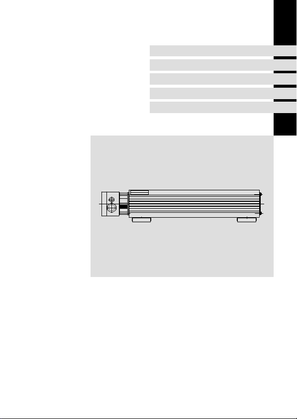
ERBSxxxxxxxx
Bremswiderstand
Brake resistor
Résistance de freinage
Resistencia de frenado
Resistenza di frenatura
Page 2

Lesen Sie zuerst diese Anleitung und die Dokumentation zum Grundgerät,
bevor Sie mit den Arbeiten beginnen!
Beachten Sie die enthaltenen Sicherheitshinweise.
Please read these instructions and the documentation of the standard
device before you start working!
Observe the safety instructions given therein!
Lire le présent fascicule et la documentation relative à l’appareil de base
avant toute manipulation de l’équipement !
Respecter les consignes de sécurité fournies.
Lea estas instrucciones y la documentación del equipo básico antes de
empezar a trabajar.
Observe las instrucciones de seguridad indicadas.
Prima di iniziare qualsiasi intervento, leggere le presenti istruzioni e la
documentazione relativa al dispositivo di base.
Osservare le note di sicurezza.
Page 3

Inhalt i
1 Über diese Dokumentation 4 . . . . . . . . . . . . . . . . . . . . . . . . . . . . . . . . . . . . . . . . . .
Informationen zur Gültigkeit 4 . . . . . . . . . . . . . . . . . . . . . . . . . . . . . . . . . . . . . . . . .
Zielgruppe 4 . . . . . . . . . . . . . . . . . . . . . . . . . . . . . . . . . . . . . . . . . . . . . . . . . . . . . . . .
Dokumenthistorie 5 . . . . . . . . . . . . . . . . . . . . . . . . . . . . . . . . . . . . . . . . . . . . . . . . . .
Verwendete Konventionen 5 . . . . . . . . . . . . . . . . . . . . . . . . . . . . . . . . . . . . . . . . . .
Verwendete Hinweise 6 . . . . . . . . . . . . . . . . . . . . . . . . . . . . . . . . . . . . . . . . . . . . . . .
2 Sicherheitshinweise 8 . . . . . . . . . . . . . . . . . . . . . . . . . . . . . . . . . . . . . . . . . . . . . . . .
Allgemeine Sicherheitshinweise 8 . . . . . . . . . . . . . . . . . . . . . . . . . . . . . . . . . . . . . .
Restgefahren 9 . . . . . . . . . . . . . . . . . . . . . . . . . . . . . . . . . . . . . . . . . . . . . . . . . . . . . .
3 Produktbeschreibung 11 . . . . . . . . . . . . . . . . . . . . . . . . . . . . . . . . . . . . . . . . . . . . . . .
Übersicht 11 . . . . . . . . . . . . . . . . . . . . . . . . . . . . . . . . . . . . . . . . . . . . . . . . . . . . . . . . .
Identifikation 12 . . . . . . . . . . . . . . . . . . . . . . . . . . . . . . . . . . . . . . . . . . . . . . . . . . . . . .
Bestimmungsgemäße Verwendung 13 . . . . . . . . . . . . . . . . . . . . . . . . . . . . . . . . . . .
Auslegungsbedingungen 14 . . . . . . . . . . . . . . . . . . . . . . . . . . . . . . . . . . . . . . . . . . . .
4 Technische Daten 16 . . . . . . . . . . . . . . . . . . . . . . . . . . . . . . . . . . . . . . . . . . . . . . . . . .
Allgemeine Daten und Einsatzbedingungen 16 . . . . . . . . . . . . . . . . . . . . . . . . . . .
Bemessungsdaten 18 . . . . . . . . . . . . . . . . . . . . . . . . . . . . . . . . . . . . . . . . . . . . . . . . . .
Mechanische Daten 20 . . . . . . . . . . . . . . . . . . . . . . . . . . . . . . . . . . . . . . . . . . . . . . .
5 Mechanische Installation 22 . . . . . . . . . . . . . . . . . . . . . . . . . . . . . . . . . . . . . . . . . . . .
Einbaufreiraum 22 . . . . . . . . . . . . . . . . . . . . . . . . . . . . . . . . . . . . . . . . . . . . . . . . . . . .
Montageschritte 23 . . . . . . . . . . . . . . . . . . . . . . . . . . . . . . . . . . . . . . . . . . . . . . . . . . .
6 Elektrische Installation 24 . . . . . . . . . . . . . . . . . . . . . . . . . . . . . . . . . . . . . . . . . . . . . .
Wichtige Hinweise 24 . . . . . . . . . . . . . . . . . . . . . . . . . . . . . . . . . . . . . . . . . . . . . . . . .
Anschlussdaten 24 . . . . . . . . . . . . . . . . . . . . . . . . . . . . . . . . . . . . . . . . . . . . . . . . . . . .
Anschlussplan 25 . . . . . . . . . . . . . . . . . . . . . . . . . . . . . . . . . . . . . . . . . . . . . . . . . . . . .
Montageschritte 26 . . . . . . . . . . . . . . . . . . . . . . . . . . . . . . . . . . . . . . . . . . . . . . . . . . .
7 Wartung 27 . . . . . . . . . . . . . . . . . . . . . . . . . . . . . . . . . . . . . . . . . . . . . . . . . . . . . . . . . .
Wartungsintervalle 27 . . . . . . . . . . . . . . . . . . . . . . . . . . . . . . . . . . . . . . . . . . . . . . . . .
Wartungsarbeiten 27 . . . . . . . . . . . . . . . . . . . . . . . . . . . . . . . . . . . . . . . . . . . . . . . . .
EDKRBS047R DE/EN/FR/ES/IT 8.0
3
Page 4

1 Über diese Dokumentation
Informationen zur Gültigkeit
0Abb. 0Tab. 0
1 Über diese Dokumentation
Informationen zur Gültigkeit
Diese Anleitung ist gültig für Bremswiderstand
ƒ ERBS015R800W
ƒ ERBS015R01K2
ƒ ERBS015R02K4
ƒ ERBS018R800W
ƒ ERBS018R01K2
ƒ ERBS018R01K4
ƒ ERBS018R01K9
ƒ ERBS018R02K8
ƒ ERBS027R600W
ƒ ERBS027R01K2
ƒ ERBS027R01K4
ƒ ERBS047R400W
ƒ ERBS047R800W
Zielgruppe
Diese Dokumentation richtet sich an qualifiziertes Fachpersonal nach IEC 60364.
Qualifiziertes Fachpersonal sind Personen, die für die auszuführenden Tätigkeiten bei der
Aufstellung, Montage, Inbetriebsetzung und dem Betrieb des Produkts über entsprechende
Qualifikationen verfügen.
Tipp!
Informationen und Hilfsmittel rund um die Lenze−Produkte finden Sie im
Download−Bereich unter
http://www.Lenze.com
4
EDKRBS047R DE/EN/FR/ES/IT 8.0
Page 5

Über diese Dokumentation
Dokumenthistorie
Dokumenthistorie
Materialnummer Version Beschreibung
.@R_ 8.0 02/2011 TD29 Überarbeitung
Verwendete Konventionen
Informationsart Auszeichnung Beispiele/Hinweise
Zahlenschreibweise
Dezimaltrennzeichen
Warnhinweise
UL−Warnhinweise
UR−Warnhinweise
Textauszeichnung
Programmname » « PC−Software
Symbole
Seitenverweis
Punkt Es wird generell der Dezimalpunkt
verwendet.
Zum Beispiel: 1234.56
Werden nur in der englischen Sprache
verwendet.
Zum Beispiel: »Engineer«, »Global
Drive Control« (GDC)
Verweis auf eine andere Seite mit zusätzlichen Informationen
Zum Beispiel:
16 = siehe Seite 16
1
EDKRBS047R DE/EN/FR/ES/IT 8.0
5
Page 6

1 Über diese Dokumentation
Verwendete Hinweise
Verwendete Hinweise
Um auf Gefahren und wichtige Informationen hinzuweisen, werden in dieser Dokumentation folgende Piktogramme und Signalwörter verwendet:
Sicherheitshinweise
Aufbau der Sicherheitshinweise:
Gefahr!
(kennzeichnet die Art und die Schwere der Gefahr)
Hinweistext
(beschreibt die Gefahr und gibt Hinweise, wie sie vermieden werden kann)
Piktogramm und Signalwort Bedeutung
Gefahr von Personenschäden durch gefährliche elektrische Spannung
Gefahr!
Gefahr!
Stop!
Hinweis auf eine unmittelbar drohende Gefahr, die den
Tod oder schwere Verletzungen zur Folge haben kann,
wenn nicht die entsprechenden Maßnahmen getroffen
werden.
Gefahr von Personenschäden durch eine allgemeine Gefahrenquelle
Hinweis auf eine unmittelbar drohende Gefahr, die den
Tod oder schwere Verletzungen zur Folge haben kann,
wenn nicht die entsprechenden Maßnahmen getroffen
werden.
Gefahr von Sachschäden
Hinweis auf eine mögliche Gefahr, die Sachschäden zur
Folge haben kann, wenn nicht die entsprechenden Maßnahmen getroffen werden.
6
EDKRBS047R DE/EN/FR/ES/IT 8.0
Page 7

Anwendungshinweise
Piktogramm und Signalwort Bedeutung
Über diese Dokumentation
Verwendete Hinweise
1
Hinweis!
Tipp!
Spezielle Sicherheitshinweise und Anwendungshinweise für UL und UR
Piktogramm und Signalwort Bedeutung
Warnings!
Warnings!
Wichtiger Hinweis für die störungsfreie Funktion
Nützlicher Tipp für die einfache Handhabung
Verweis auf andere Dokumentation
Sicherheitshinweis oder Anwendungshinweis für den
Betrieb eines UL−approbierten Geräts in UL−approbierten
Anlagen.
Möglicherweise wird das Antriebssystem nicht UL−gerecht betrieben, wenn nicht die entsprechenden Maßnahmen getroffen werden.
Sicherheitshinweis oder Anwendungshinweis für den
Betrieb eines UR−approbierten Geräts in UL−approbierten
Anlagen.
Möglicherweise wird das Antriebssystem nicht UL−gerecht betrieben, wenn nicht die entsprechenden Maßnahmen getroffen werden.
EDKRBS047R DE/EN/FR/ES/IT 8.0
7
Page 8

2 Sicherheitshinweise
Allgemeine Sicherheitshinweise
2 Sicherheitshinweise
Allgemeine Sicherheitshinweise
Gefahr!
Wenn Sie die folgenden grundlegenden Sicherheitsmaßnahmen missachten,
kann dies zu schweren Personenschäden und Sachschäden führen:
ƒ Lenze−Antriebs− und Automatisierungskomponenten ...
... ausschließlich bestimmungsgemäß verwenden.
... niemals trotz erkennbarer Schäden in Betrieb nehmen.
... niemals technisch verändern.
... niemals unvollständig montiert in Betrieb nehmen.
... niemals ohne erforderliche Abdeckungen betreiben.
... können während und nach dem Betrieb − ihrer Schutzart entsprechend − spannungsführende, auch bewegliche oder rotierende Teile haben. Oberflächen können heiß sein.
ƒ Alle Vorgaben der beiliegenden und zugehörigen Dokumentation beachten.
Dies ist Voraussetzung für einen sicheren und störungsfreien Betrieb sowie für das Erreichen der angegebenen Produkteigenschaften.
Die in diesem Dokument dargestellten verfahrenstechnischen Hinweise und Schaltungsausschnitte sind Vorschläge, deren Übertragbarkeit auf die jeweilige Anwendung
überprüft werden muss. Für die Eignung der angegebenen Verfahren und Schaltungsvorschläge übernimmt der Hersteller keine Gewähr.
ƒ Alle Arbeiten mit und an Lenze−Antriebs− und Automatisierungskomponenten darf
nur qualifiziertes Fachpersonal ausführen.
Nach IEC 60364 bzw. CENELEC HD 384 sind dies Personen, ...
... die mit Aufstellung, Montage, Inbetriebsetzung und Betrieb des Produkts vertraut
sind.
... die über die entsprechenden Qualifikationen für ihre Tätigkeit verfügen.
... die alle am Einsatzort geltenden Unfallverhütungsvorschriften, Richtlinien und Gesetze kennen und anwenden können.
8
EDKRBS047R DE/EN/FR/ES/IT 8.0
Page 9

Sicherheitshinweise
Restgefahren
Gefahr!
Gefährliche elektrische Spannung
Während des Betriebs des Grundgeräts und bis zu 3 Minuten nach dem
Netzabschalten können an den Anschlüssen des Bremswiderstands gefährliche
elektrische Spannungen anliegen.
Mögliche Folgen:
ƒ Tod oder schwere Verletzungen beim Berühren der Anschlussklemmen.
Schutzmaßnahmen:
ƒ Vor allen Arbeiten am Bremswiderstand das Grundgerät vom Netz
trennen.
ƒ Alle Leistungsklemmen auf Spannungsfreiheit prüfen.
ƒ Den Montageort so wählen, dass die in den Technischen Daten genannten
Einsatzbedingungen immer gewährleistet sind.
Gefahr!
Heiße Oberfläche während des Betriebs
Der Bremswiderstand wird während des Betriebs sehr heiß. (Temperaturen
siehe Technische Daten.)
Mögliche Folgen:
ƒ Schwere Verbrennungen beim Berühren des Bremswiderstands.
ƒ Feuer oder Schwelbrand, wenn sich brennbare Materialien oder Stoffe in
der Nähe des Bremswiderstands befinden oder dorthin gelangen können.
Schutzmaßnahmen:
ƒ Vor Arbeiten am Bremswiderstand dessen Oberflächentemperatur prüfen.
ƒ Den Montageort so wählen, dass die in den Technischen Daten genannten
Einsatzbedingungen immer gewährleistet sind.
ƒ Den Montageort durch geeignete Brandschutzmaßnahmen und einen
Berührschutz sichern.
Restgefahren
2
EDKRBS047R DE/EN/FR/ES/IT 8.0
9
Page 10

2 Sicherheitshinweise
Restgefahren
Warnings!
Conditions of Acceptability:
ƒ The products covered by this report are intended for use with Power
Conversion Equipment (drives) only.
ƒ The Temperature Switch must be connected to the drive, so that the drive
switches off in case when the maximum operating temperature is
exceeded.
ƒ Temperature tests and abnormal operation tests have only been
conducted for single resistive elements and for continuous duty as
indicated under RATINGS. For any grouping of the resistor elements an
additional temperature test must be conducted, depending on the
evaluation of the mechanical construction and the expected temperature
rise.
ƒ For any duty cycle operation in the end−use application it must be
guaranteed that the maximum Wattage rating will not be exceeded. This
may be evaluated by calculation. If there will be any concern regarding to
this, additional temperature tests have to be conducted under end−use
conditions.
10
EDKRBS047R DE/EN/FR/ES/IT 8.0
Page 11
3 Produktbeschreibung
Übersicht
Lieferumfang
Pos. Beschreibung
Bremswiderstand
Montageanleitung
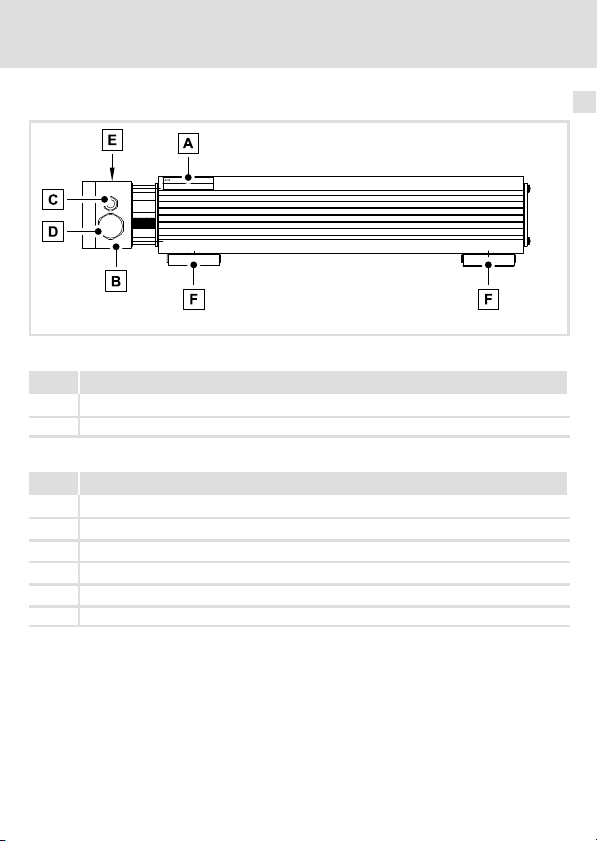
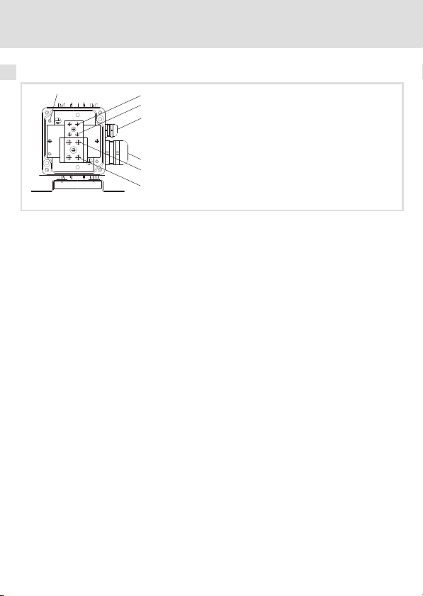
Elemente am Bremswiderstand
Pos. Beschreibung
Typenschild
Klemmenkasten
Kabelverschraubung Thermokontakt−Leitung
Kabelverschraubung Bremswiderstand−Leitung
Warnhinweis
Befestigungswinkel
Produktbeschreibung
Übersicht
3
ERBS101
EDKRBS047R DE/EN/FR/ES/IT 8.0
11
Page 12
3 Produktbeschreibung
Identifikation
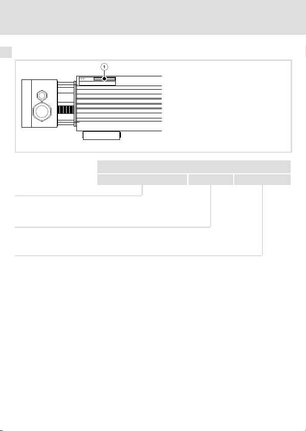
Identifikation
Typenschlüssel ERBx xxxx xxxx
Produktreihe
Widerstand RB [W]
z. B.
470R = 470
W
075D = 7.5 W
Dauerleistung Pd [W]
z. B. 120W = 120 W
01K2 = 1.2 kW
ERBS104
12
EDKRBS047R DE/EN/FR/ES/IT 8.0
Page 13

Bestimmungsgemäße Verwendung
Produktbeschreibung
Bestimmungsgemäße Verwendung
Bremswiderstände
ƒ nur unter den in dieser Betriebsanleitung vorgeschriebenen Einsatzbedingungen
betreiben.
ƒ sind Komponenten
– zum Einbau in eine Maschine.
– zum Zusammenbau mit anderen Komponenten zu einer Maschine.
Die Inbetriebnahme des Bremswiderstands ist solange untersagt, bis festgestellt
wurde, dass die Maschine, in welche der Bremswiderstand eingebaut werden soll, den
Bestimmungen der EG−Maschinenrichtlinie entsprechen.
ƒ sind elektrische Betriebsmittel zum Einbau in Schaltschränke oder ähnliche
abgeschlossene Betriebsräume.
ƒ erfüllen die Schutzanforderungen der EG−Richtlinie "Niederspannung".
ƒ sind keine Maschinen im Sinne der EG−Richtlinie Maschinen.
ƒ sind keine Haushaltsgeräte, sondern als Komponenten ausschließlich für die
Weiterverwendung zur gewerblichen Nutzung bestimmt.
Antriebssysteme mit Bremswiderständen
ƒ Die Verantwortung für die Einhaltung der EG−Richtlinien in der
Maschinenanwendung liegt beim Weiterverwender.
Jede andere Verwendung gilt als sachwidrig!
3
EDKRBS047R DE/EN/FR/ES/IT 8.0
13
Page 14

3 Produktbeschreibung
Auslegungsbedingungen
Auslegungsbedingungen
Beim Einsatz von Bremswiderständen beachten:
ƒ Mittelwert der generatorischen Leistung < Dauerleistung P
ƒ Generatorische Leistung während der Bremszeit < Wärmemenge Q
Bremswiderstands.
ƒ Bremszeit < 10 % der Zykluszeit (Bremszeit + Pausenzeit).
ƒ Thermokontakt immer anschließen und so in die Anlagenüberwachung einbinden,
dass bei Überhitzung des Bremswiderstands die Netzversorgung des Grundgeräts
abgeschaltet wird.
Zu jedem Zeitpunkt muss gelten: Im Zeitintervall t
die kumulierten Bremszeiten t
Berechnung
Bremswiderstand−Zyklus t
Q
t
cyc,RB
Q
B
P
d
Max. Bremsdauer t
t
brk,max
Q
B
R
B
U
max
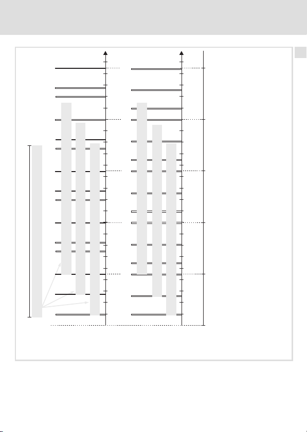
Beispiele für die Auswertung der Bedingung
Gegeben ist der Bremswiderstandzyklus t
10 s. Die Bremszeiten t
B
+
mit
P
d
Wärmemenge in Ws
Dauerleistung in W
brk,max
@ R
Q
B
+
Wärmemenge in Ws
Widerstand in W
Max. Betriebsspannung in V
B
2
U
max
brk
immer £ der maximalen Bremsdauer t
brk
:
cyc,RB
innerhalb des Zeitintervalls t
mit
und der Prozesszyklus t
cyc,RB
= 150 s und die max. Bremsdauer t
cyc,RB
cyc,Prc
des Bremswiderstands.
d
des
B
(Bremswiderstandzyklus) müssen
:
cyc,RB
sind beispielhaft.
brk,max
sein.
brk,max
=
14
EDKRBS047R DE/EN/FR/ES/IT 8.0
Page 15
Produktbeschreibung
£
£
£
£
³
£
Auslegungsbedingungen
3
0.5 0.5
1
1
ü
0.5 0.5
1
ü
ü
0.5 0.5
1
= 6.5 s
brk brk,max
tt
S
= 150 s
cyc,RB
t
Im oberen Beispiel wird die Auslegungsbedingung zu jedem Zeitpunkt eingehalten. Im unteren Beispiel wird die Auslegungsbedingungen einmal nicht eingehalten, das heißt, der
gewählte Bremswiderstand ist für den vorgegebenen Prozess nicht geeignet. Setzen Sie einen Bremswiderstand mit größerer Leistung (kürzerem Bremswiderstandzyklus t
= 6.5 s
brk brk,max
tt
S
0.5 0.5
0.5 0.5
1 1
[s]
brk
t
= 7 s
brk brk,max
tt
S
1 11
û
ü
ü
= 11 s
1 1
brk brk,max
tt
S
= 10 s
brk brk,max
tt
S
1 1
11111
1 1
1010 5050 100100 200200150150
t [s]
[s]
brk
t
cyc,Prs
t
û
cyc,Prs
t
cyc,Prs
t
ü
= 10 s
cyc,Prs
t
brk brk,max
tt
S
cyc,Prs
t
1010 5050 100100 200200150150
t [s]
cyc,RB
) ein.
EDKRBS047R DE/EN/FR/ES/IT 8.0
15
Page 16

4 Technische Daten
Allgemeine Daten und Einsatzbedingungen
4 Technische Daten
Allgemeine Daten und Einsatzbedingungen
Konformität und Approbation
Konformität
CE
Approbation
UR UL508 Industrial Control Equipment, Underwriter Laborato-
Personenschutz und Geräteschutz
Schutzart
Thermokontakt
Ausführung Öffner, 230 °C
Schaltleistung 250 V AC / 5 A
2006/95/EG Niederspannungsrichtlinie
ries (File−No. E232497) for USA and Canada
EN 60529
NEMA 250 Berührschutz nach Typ 4
IP65
Umweltbedingungen
Klima
Lagerung IEC/EN 60721−3−1 1K3 (−25 ... +60 °C)
Transport IEC/EN 60721−3−2 2K3 (−25 ... +70 °C)
Betrieb IEC/EN 60721−3−3 3K3 (−10 ... +55 °C)
Aufstellhöhe 0 ... 4000 m üNN
Rüttelfestigkeit
(9,81 m/s2 = 1 g)
EN 50178,
IEC 61800−5−1,
Germanischer
Loyd, allgemeine
Bedingungen
Stromreduzierung von +45 ... +55 °C: 2.5 %/°C
1000 ... 4000 m üNN: Stromreduzierung 5 %/1000 m
Beschleunigungsfest bis 1 g
16
EDKRBS047R DE/EN/FR/ES/IT 8.0
Page 17

Allgemeine Daten und Einsatzbedingungen
Technische Daten
Montagebedingungen
Montageort
Einbaulage
Standard Vertikal−hängend mit Anschlüssen unten
Variante Horizontal−stehend mit Befestigungswinkel unten
Einbaufreiräume
Standard 22
Variante 23
l Der Montageort muss den in den "Allgemeinen
Daten" genannten Geräteeigenschaften entsprechen.
l Brennbare Materialien oder Stoffe dürfen sich nicht
in der Nähe des Bremswiderstands befinden.
l Die vom Bremswiderstand erzeugte Wärme muss
ungehindert abgeführt werden.
4
EDKRBS047R DE/EN/FR/ES/IT 8.0
17
Page 18

4 Technische Daten
Bemessungsdaten
Bemessungsdaten
Elektrische Daten
R
B
[W]
ERBS015R800W
ERBS015R01K2 1200 180
ERBS015R02K4 2400 420
ERBS018R800W
ERBS018R01K2 1200 180
ERBS018R01K4 1400 210
ERBS018R01K9 1900 285
ERBS018R02K8 2800 420
ERBS027R600W
ERBS027R01K2 1200 180
ERBS027R01K4 1400 210
ERBS047R400W
ERBS047R800W 800 120
R
B
P
d
Q
B
U
max
Widerstand
Dauerleistung
Wärmemenge
Max. Betriebsspannung
15
18
27
47
P
d
[W] [kWs] [VDC]
800 120
800 120
600 90
400 60
Q
B
U
max
800
18
EDKRBS047R DE/EN/FR/ES/IT 8.0
Page 19

Technische Daten
Bemessungsdaten
Temperaturen
T
nom
an der Oberfläche 250 400 1000
an der Einbaufreiraumgrenze
T
nom
T
TK
T
max
*) Gemessen bei Umgebungsmedium Luft (kleine Wärmeleitzahl); wenn sich
*)
Maximale Temperatur bei Bessungsdaten
Temperatur bei der der Thermokontakt auslöst
Maximale Temperatur bei sachwidriger Verwendung
Materialien/Stoffe an der Einbaufreiraumgrenze befinden, die sich aufheizen (größere
Wärmeleitzahl), steigt die Temperatur weiter an.
120 200 300
T
[°C]
TK
4
T
max
EDKRBS047R DE/EN/FR/ES/IT 8.0
19
Page 20
4 Technische Daten
Mechanische Daten
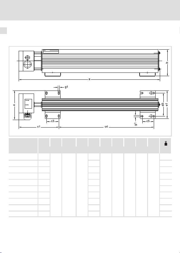
Mechanische Daten
Bauform 1
a b c1 c3 c4 c5 d3 e e1 g1
[mm] [kg]
ERBS015R800W 710
ERBS015R01K2 1020 841 5.6
ERBS018R800W 710 531 4.0
ERBS018R01K2 1020 841 5.6
ERBS018R01K4 1110 931 6.3
ERBS027R600W 550 371 3.1
ERBS027R01K2 1020 841 5.6
ERBS027R01K4 1110 931 6.3
ERBS047R400W 400 221 2.3
ERBS047R800W 710 531 4.0
105 155.5 48
531
45 90 114 110 6.2
ERBS102
4.0
20
EDKRBS047R DE/EN/FR/ES/IT 8.0
Page 21
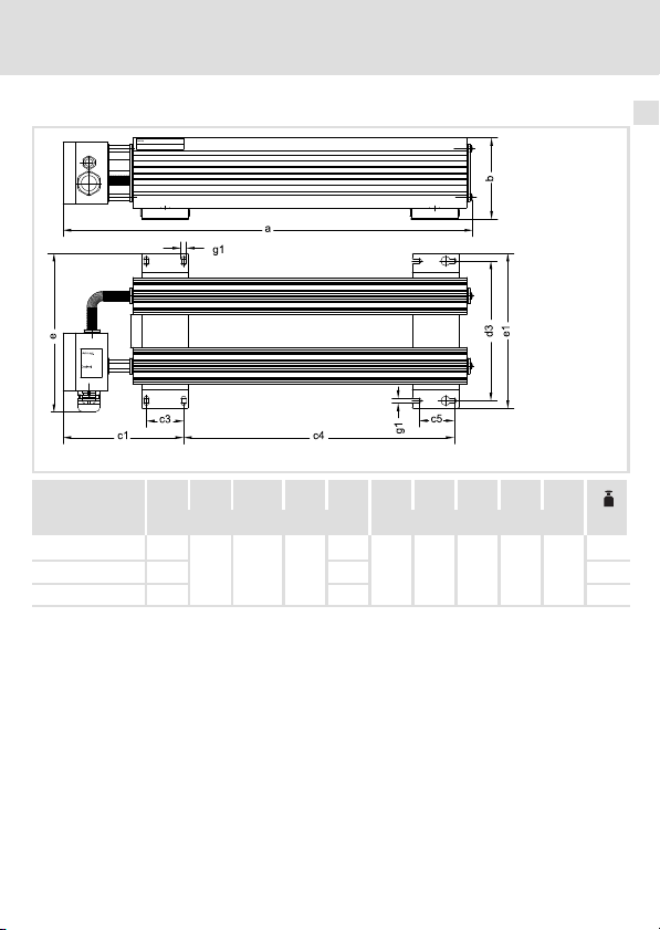
Bauform 2
ERBS015R02K4 1020
ERBS018R01K9 825
ERBS018R02K8 1110
Technische Daten
Mechanische Daten
a b c1 c3 c4 c5 d3 e e1 g1
[mm] [mm] [kg]
841
105 155.5 48
646
45 180 204 200 6.2
931
4
ERBS107
10.0
8.7
12.0
EDKRBS047R DE/EN/FR/ES/IT 8.0
21
Page 22
5 Mechanische Installation
Einbaufreiraum
5 Mechanische Installation
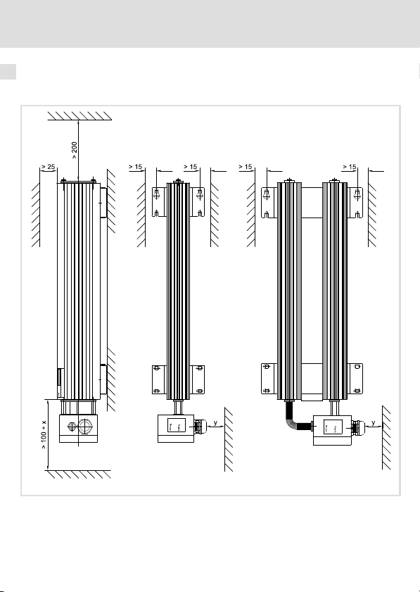
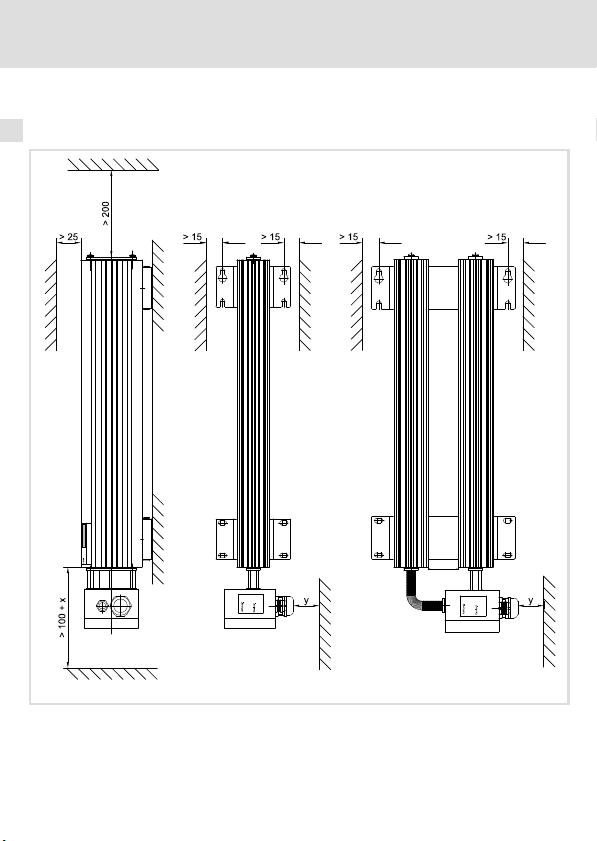
Einbaufreiraum
Einbaufreiräume bei Standardmontage
x Verdrahtungsfreiraum
y Kabelbiegeradius
Alle Maße in Millimeter
22
ERBS106
EDKRBS047R DE/EN/FR/ES/IT 8.0
Page 23
Mechanische Installation
Montageschritte
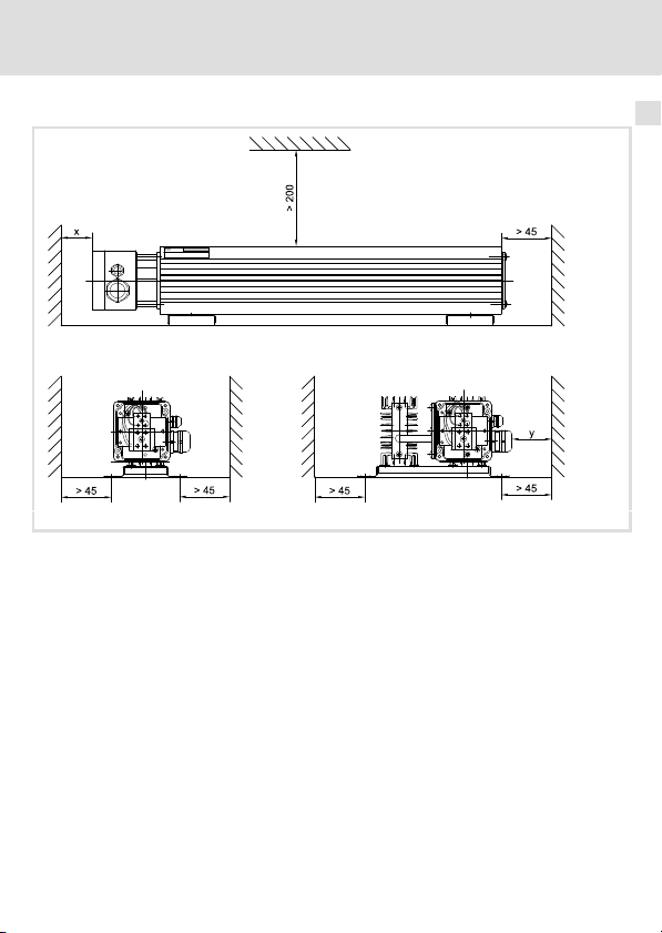
Einbaufreiräume bei Montagevariante
x Verdrahtungsfreiraum
y Kabelbiegeradius
Alle Maße in Millimeter
Montageschritte
So montieren Sie den Bremswiderstand:
1. Wählen Sie einen geeigneten Montageort.
– Der Montageort muss die in den Technischen Daten genannten
Einsatzbedingungen immer gewährleisten; ggf. zusätzliche Maßnahmen
ergreifen.
– Eine ungehinderte Luftzirkulation zum Abführen der Wärme muss gewährleistet
sein.
2. Verschrauben Sie den Bremswiderstand am Montageort.
– Der Montageort und das Montagematerial muss die mechanische Verbindung
dauerhaft gewährleisten.
5
ERBS105
EDKRBS047R DE/EN/FR/ES/IT 8.0
23
Page 24

6 Elektrische Installation
Wichtige Hinweise
6 Elektrische Installation
Wichtige Hinweise
Stop!
Mögliche Überhitzung des Bremswiderstands während des Betriebs
Durch ungenügende Wärmeabfuhr kann der Bremswiderstand während des
Betriebs überhitzen.
Mögliche Folgen:
ƒ Der Bremswiderstand wird zerstört.
ƒ Der Antrieb wird nicht abgebremst sondern trudelt aus.
Schutzmaßnahmen:
ƒ Den Thermokontakt des Bremswiderstands immer anschließen.
ƒ Den Thermokontakt so in die Anlagenüberwachung einbinden, dass bei
Überhitzung des Bremswiderstands die Netzversorgung des Grundgerätes
Anschlussdaten
RB1, RB2
(Bremswiderstand)
PE
(Schutzleiter)
T1, T2
(Thermokontakt)
abgeschaltet wird (z. B. die Netzschütz−Ansteuerung abschalten).
Kabelverschrau-
bung
M25
M12 Schraubklemme
Anschlussart Anschlussgröße Anzugsmoment
Schraubklemme
Schraube M4
0.5 ... 10 mm
20 ... 6 AWG
0.25 ... 4 mm
24 ... 12 AWG
2
13.3 ... 15.9 lb−in
19.5 ... 23.9 lb−in
2
1.5 ... 1.8 Nm
2.2 ... 2.7 Nm
0.6 ... 0.8 Nm
5.3 ... 7.1 lb−in
24
EDKRBS047R DE/EN/FR/ES/IT 8.0
Page 25

Anschlussplan
Variante 1 (kurze Leitungen)
R
B
RB1 RB2
Variante 2 (lange Leitungen)
R
B
RB1 RB2
T1 T2
PE
Verdrillte Leitungen
T1 T2
PE
PES
PES
< 0.5 m
<5m
Elektrische Installation
Anschlussplan
ERBG008
6
HF−Schirmabschluss durch großflächige PE−Anbindung
Verdrillte Leitungen
EDKRBS047R DE/EN/FR/ES/IT 8.0
ERBG007
25
Page 26
6 Elektrische Installation
Montageschritte
Montageschritte
PE
So schließen Sie den Bremswiderstand an:
1. Grundgerät vom Netz trennen und alle Leistungsklemmen auf Spannungsfreiheit
prüfen.
2. Klemmenabdeckung demontieren.
3. Bremswiderstand−Leitung auflegen:
– Bei einer Leitungslänge bis 0.5 m verdrillte Leitung verwenden (Anschlussplan
Variante 1).
– Bei einer Leitungslänge bis 5 m geschirmte Leitung verwenden (Anschlussplan
Variante 2).
– Leitung durch Kabelverschraubung ziehen.
– Adern am Bremswiderstand am Anschluss RB1, RB2 und PE auflegen, dabei
Anzugsmoment beachten. PE−Anschluss nach EN 61800−5−1 ausführen.
– Kabelverschraubung festziehen.
Bei geschirmter Leitung: Der Schirm muss fest und großflächig mit der
Kabelverschraubung verbunden sein.
– Adern und Schirm am Grundgerät auflegen, dabei Dokumentation des
Grundgerätes beachten.
4. Thermokontakt−Leitungen auflegen:
– Verdrillte Leitung verwenden.
– Leitung durch Kabelverschraubung ziehen.
– Adern am Bremswiderstand am Anschluss T1 und T2 auflegen, dabei
Anzugsmoment beachten.
– Kabelverschraubung festziehen.
– Den Thermokontakt so in die Anlagenüberwachung einbinden, dass bei
Überhitzung des Bremswiderstands die Netzversorgung abgeschaltet wird.
5. Klemmenabdeckung montieren.
1
0
T1
T2
RB1
RB2
ERBS103
26
EDKRBS047R DE/EN/FR/ES/IT 8.0
Page 27

Wartung
Wartungsintervalle
7 Wartung
Wartungsintervalle
Der Bremswiderstand ist wartungsfrei. Trotzdem müssen Sie in regelmäßigen und unter
Berücksichtigung der Umgebungsbedingungen ausreichend kurzen Intervallen eine Sichtprüfung durchführen.
Kontrollieren Sie:
ƒ Entspricht die Umgebung des Bremswiderstands noch den in den Technischen Daten
genannten Einsatzbedingungen?
ƒ Behindert kein Staub oder Schmutz die Wärmeabfuhr des Bremswiderstands?
ƒ Sind die mechanischen und elektrischen Verbindungen in Ordnung?
Wartungsarbeiten
Bremswiderstand reinigen
1. Grundgerät vom Netz trennen und mindestens 3 Minuten warten.
2. Temperatur des Bremswiderstands prüfen, ggf. abkühlen lassen.
3. Anschlüsse des Bremswiderstands auf Spannungsfreiheit prüfen.
4. Bremswiderstand ohne Reinigungsmittel säubern.
7
EDKRBS047R DE/EN/FR/ES/IT 8.0
27
Page 28

7 Wartung
Wartungsarbeiten
28
EDKRBS047R DE/EN/FR/ES/IT 8.0
Page 29

Contents i
1 About this documentation 30 . . . . . . . . . . . . . . . . . . . . . . . . . . . . . . . . . . . . . . . . . . .
Validity information 30 . . . . . . . . . . . . . . . . . . . . . . . . . . . . . . . . . . . . . . . . . . . . . . . .
Target group 30 . . . . . . . . . . . . . . . . . . . . . . . . . . . . . . . . . . . . . . . . . . . . . . . . . . . . . .
Document history 30 . . . . . . . . . . . . . . . . . . . . . . . . . . . . . . . . . . . . . . . . . . . . . . . . . .
Conventions used 31 . . . . . . . . . . . . . . . . . . . . . . . . . . . . . . . . . . . . . . . . . . . . . . . . . .
Notes used 32 . . . . . . . . . . . . . . . . . . . . . . . . . . . . . . . . . . . . . . . . . . . . . . . . . . . . . . . .
2 Safety instructions 34 . . . . . . . . . . . . . . . . . . . . . . . . . . . . . . . . . . . . . . . . . . . . . . . . .
General safety instructions 34 . . . . . . . . . . . . . . . . . . . . . . . . . . . . . . . . . . . . . . . . . .
Residual hazards 35 . . . . . . . . . . . . . . . . . . . . . . . . . . . . . . . . . . . . . . . . . . . . . . . . . . .
3 Product description 37 . . . . . . . . . . . . . . . . . . . . . . . . . . . . . . . . . . . . . . . . . . . . . . . . .
Overview 37 . . . . . . . . . . . . . . . . . . . . . . . . . . . . . . . . . . . . . . . . . . . . . . . . . . . . . . . . .
Identification 38 . . . . . . . . . . . . . . . . . . . . . . . . . . . . . . . . . . . . . . . . . . . . . . . . . . . . . .
Application as directed 39 . . . . . . . . . . . . . . . . . . . . . . . . . . . . . . . . . . . . . . . . . . . . . .
Dimensioning conditions 40 . . . . . . . . . . . . . . . . . . . . . . . . . . . . . . . . . . . . . . . . . . . .
4 Technical data 42 . . . . . . . . . . . . . . . . . . . . . . . . . . . . . . . . . . . . . . . . . . . . . . . . . . . . .
General data and operating conditions 42 . . . . . . . . . . . . . . . . . . . . . . . . . . . . . . .
Rated data 44 . . . . . . . . . . . . . . . . . . . . . . . . . . . . . . . . . . . . . . . . . . . . . . . . . . . . . . . .
Mechanical data 46 . . . . . . . . . . . . . . . . . . . . . . . . . . . . . . . . . . . . . . . . . . . . . . . . . .
5 Mechanical installation 48 . . . . . . . . . . . . . . . . . . . . . . . . . . . . . . . . . . . . . . . . . . . . .
Mounting clearance 48 . . . . . . . . . . . . . . . . . . . . . . . . . . . . . . . . . . . . . . . . . . . . . . . .
Mounting steps 49 . . . . . . . . . . . . . . . . . . . . . . . . . . . . . . . . . . . . . . . . . . . . . . . . . . . .
6 Electrical installation 50 . . . . . . . . . . . . . . . . . . . . . . . . . . . . . . . . . . . . . . . . . . . . . . .
Important notes 50 . . . . . . . . . . . . . . . . . . . . . . . . . . . . . . . . . . . . . . . . . . . . . . . . . . .
Connection data 50 . . . . . . . . . . . . . . . . . . . . . . . . . . . . . . . . . . . . . . . . . . . . . . . . . . .
Connection plan 51 . . . . . . . . . . . . . . . . . . . . . . . . . . . . . . . . . . . . . . . . . . . . . . . . . . .
Mounting steps 52 . . . . . . . . . . . . . . . . . . . . . . . . . . . . . . . . . . . . . . . . . . . . . . . . . . . .
7 Maintenance 53 . . . . . . . . . . . . . . . . . . . . . . . . . . . . . . . . . . . . . . . . . . . . . . . . . . . . . .
Maintenance intervals 53 . . . . . . . . . . . . . . . . . . . . . . . . . . . . . . . . . . . . . . . . . . . . . .
Maintenance operations 53 . . . . . . . . . . . . . . . . . . . . . . . . . . . . . . . . . . . . . . . . . . . .
EDKRBS047R DE/EN/FR/ES/IT 8.0
29
Page 30

1 About this documentation
Validity information
0Fig. 0Tab. 0
1 About this documentation
Validity information
These instructions are valid for brake resistors
ƒ ERBS015R800W
ƒ ERBS015R01K2
ƒ ERBS015R02K4
ƒ ERBS018R800W
ƒ ERBS018R01K2
ƒ ERBS018R01K4
ƒ ERBS018R01K9
ƒ ERBS018R02K8
ƒ ERBS027R600W
ƒ ERBS027R01K2
ƒ ERBS027R01K4
ƒ ERBS047R400W
ƒ ERBS047R800W
Target group
This documentation is directed at qualified skilled personnel according to IEC 60364.
Qualified skilled personnel are persons who have the required qualifications to carry out all
activities involved in installing, mounting, commissioning, and operating the product.
Tip!
Information and auxiliary devices around the Lenze products can be found in
the download area at
http://www.Lenze.com
Document history
Material number Version Description
.@R_ 8.0 02/2011 TD29 Revision
30
EDKRBS047R DE/EN/FR/ES/IT 8.0
Page 31

About this documentation
Conventions used
Conventions used
Type of information Identification Examples/notes
Spelling of numbers
Decimal separator
Warnings
UL warnings
UR warnings
Text
Program name » « PC software
Icons
Page reference
Point In general, the decimal point is used.
For instance: 1234.56
Are only given in English.
For example: »Engineer«, »Global
Drive Control« (GDC)
Reference to another page with
additional information
For instance: 16 = see page 16
1
EDKRBS047R DE/EN/FR/ES/IT 8.0
31
Page 32

1 About this documentation
Notes used
Notes used
The following pictographs and signal words are used in this documentation to indicate
dangers and important information:
Safety instructions
Structure of safety instructions:
Danger!
(characterises the type and severity of danger)
Note
(describes the danger and gives information about how to prevent dangerous
situations)
Pictograph and signal word Meaning
Danger of personal injury through dangerous electrical
Danger!
Danger!
Stop!
voltage.
Reference to an imminent danger that may result in
death or serious personal injury if the corresponding
measures are not taken.
Danger of personal injury through a general source of
danger.
Reference to an imminent danger that may result in
death or serious personal injury if the corresponding
measures are not taken.
Danger of property damage.
Reference to a possible danger that may result in
property damage if the corresponding measures are not
taken.
32
EDKRBS047R DE/EN/FR/ES/IT 8.0
Page 33

Application notes
Pictograph and signal word Meaning
About this documentation
Notes used
1
Note!
Tip!
Special safety instructions and application notes for UL and UR
Pictograph and signal word Meaning
Warnings!
Warnings!
Important note to ensure troublefree operation
Useful tip for simple handling
Reference to another documentation
Safety or application note for the operation of a
UL−approved device in UL−approved systems.
Possibly the drive system is not operated in compliance
with UL if the corresponding measures are not taken.
Safety or application note for the operation of a
UR−approved device in UL−approved systems.
Possibly the drive system is not operated in compliance
with UL if the corresponding measures are not taken.
EDKRBS047R DE/EN/FR/ES/IT 8.0
33
Page 34

2 Safety instructions
General safety instructions
2 Safety instructions
General safety instructions
Danger!
Disregarding the following basic safety measures may lead to severe personal
injury and damage to material assets!
ƒ Lenze drive and automation components ...
... must only be used for the intended purpose.
... must never be operated if damaged.
... must never be subjected to technical modifications.
... must never be operated unless completely assembled.
... must never be operated without the covers/guards.
... can − depending on their degree of protection − have live, movable or rotating parts
during or after operation. Surfaces can be hot.
ƒ All specifications of the corresponding enclosed documentation must be observed.
This is vital for a safe and trouble−free operation and for achieving the specified product
features.
The procedural notes and circuit details provided in this document are proposals which
the user must check for suitability for his application. The manufacturer does not accept
any liability for the suitability of the specified procedures and circuit proposals.
ƒ Only qualified skilled personnel are permitted to work with or on Lenze drive and
automation components.
According to IEC 60364 or CENELEC HD 384, these are persons ...
... who are familiar with the installation, assembly, commissioning and operation of the
product,
... possess the appropriate qualifications for their work,
... and are acquainted with and can apply all the accident prevent regulations, directives
and laws applicable at the place of use.
34
EDKRBS047R DE/EN/FR/ES/IT 8.0
Page 35

Safety instructions
Residual hazards
Residual hazards
Danger!
Dangerous electrical voltage
The terminals of the brake resistor may carry dangerous voltages during
operation of the basic device and up to three minutes after mains
disconnection.
Possible consequences:
ƒ Death or severe injuries when touching the terminals.
Protective measures:
ƒ Before working on the brake resistor disconnect the basic device from the
mains.
ƒ Check all power terminals for safe isolation from supply.
ƒ Select the mounting location so that the operating conditions mentioned
in the technical data are always ensured.
Danger!
Hot surface during operation
During operation, the brake resistor becomes very hot. (For temperatures, see
Technical data.)
Possible consequences:
ƒ Severe burns when touching the brake resistor.
ƒ Fire or smouldering fire if flammable materials or substances are placed
near the brake resistor or may get to it.
Protective measures:
ƒ Before working on the brake resistor, check its surface temperature.
ƒ Select the mounting location so that the operating conditions mentioned
in the technical data are always ensured.
ƒ Protect the mounting location by suitable fire prevention and protection
against contact.
2
EDKRBS047R DE/EN/FR/ES/IT 8.0
35
Page 36

2 Safety instructions
Residual hazards
Warnings!
Conditions of Acceptability:
ƒ The products covered by this report are intended for use with Power
Conversion Equipment (drives) only.
ƒ The Temperature Switch must be connected to the drive, so that the drive
switches off in case when the maximum operating temperature is
exceeded.
ƒ Temperature tests and abnormal operation tests have only been
conducted for single resistive elements and for continuous duty as
indicated under RATINGS. For any grouping of the resistor elements an
additional temperature test must be conducted, depending on the
evaluation of the mechanical construction and the expected temperature
rise.
ƒ For any duty cycle operation in the end−use application it must be
guaranteed that the maximum Wattage rating will not be exceeded. This
may be evaluated by calculation. If there will be any concern regarding to
this, additional temperature tests have to be conducted under end−use
conditions.
36
EDKRBS047R DE/EN/FR/ES/IT 8.0
Page 37

3 Product description
Overview
Scope of supply
Pos. Description
Brake resistor
Mounting Instructions
Brake resistor elements
Pos. Description
Nameplate
Terminal box
Cable gland for thermal contact cable
Cable gland for brake resistor cable
Warning note
Fixing bracket
Product description
Overview
3
ERBS101
EDKRBS047R DE/EN/FR/ES/IT 8.0
37
Page 38

3 Product description
Identification
Identification
Type code ERBx xxxx xxxx
Product series
Resistance RB [W]
e.g.
470R = 470
W
075D = 7.5 W
Permanent power Pd [W]
e.g. 120W = 120 W
01k2 = 1.2 kW
ERBS104
38
EDKRBS047R DE/EN/FR/ES/IT 8.0
Page 39

Product description
Application as directed
Application as directed
Brake resistors
ƒ must only be actuated under the operating conditions specified in these operating
instructions.
ƒ are components
– for mounting in a machine.
– for assembly with other components to a machine.
Commissioning of the brake resistor is prohibited until it has been determined that the
machine into which the brake resistor is to be mounted complies with the regulations
of the EC Machinery Directive.
ƒ are electrical equipment for mounting in control cabinets or similar closed electrical
operating areas.
ƒ comply with the protective requirements of the "Low voltage" EC Directive.
ƒ are not machines as defined by the Machines EC Directive.
ƒ are not household appliances, but are only designed as components for subsequent
commercial use.
Drive systems with brake resistors
ƒ The responsibility for compliance with the EC Directives in the machine application is
that of the re−user.
Any other use shall be deemed inappropriate!
3
EDKRBS047R DE/EN/FR/ES/IT 8.0
39
Page 40

3 Product description
Dimensioning conditions
Dimensioning conditions
If brake resistors are used, observe the following:
ƒ Mean value of regenerative power < permanent power P
ƒ Regenerative power during braking time < heat quantity Q
ƒ Braking time < 10 % of cycle time (braking time + dead time).
ƒ Always connect the thermal contact and integrate it in a way into the system
monitoring that the mains supply will be switched off when the standard device is
overheated.
At all times, the following must apply: In the time interval t
cumulative braking times t
.
t
brk,max
Calculation
Brake resistor cycle t
t
+
cyc,RB
Q
B
P
d
Max. total braking time t
t
+
brk,max
Q
B
R
B
U
max
Examples of the evaluation of the condition
The brake resistor cycle t
given. The braking times t
cyc,RB
Q
B
with
P
d
Heat quantity in Ws
Permanent power in W
@ R
Q
B
U
max
Heat quantity in Ws
Resistance in W
Max. operating voltage in V
must always be £ of the maximum total braking time
brk
:
within the time interval t
brk,max
B
with
2
= 150 s and the max. total braking time t
cyc,RB
and the process cycle t
brk
cyc,RB
are exemplary.
cyc,Prc
d
cyc,RB
of the brake resistor.
of the brake resistor.
B
(brake resistor cycle) the
:
brk,max
= 10 s are
40
EDKRBS047R DE/EN/FR/ES/IT 8.0
Page 41

Product description
£
£
£
£
³
£
Dimensioning conditions
3
0.5 0.5
1
1
ü
0.5 0.5
1
ü
ü
0.5 0.5
1
= 6.5 s
brk brk,max
tt
S
= 150 s
cyc,RB
t
In the above example, the dimensioning condition is observed at all times. In the example
below, the dimensioning condition is once not observed, which means that the brake
resistor selected is not suitable for the process specified. Use a brake resistor with a greater
power (shorter brake resistor cycle t
= 6.5 s
brk brk,max
tt
S
0.5 0.5
0.5 0.5
1 1
[s]
brk
t
= 7 s
brk brk,max
tt
S
1 11
û
ü
ü
= 11 s
1 1
brk brk,max
tt
S
= 10 s
brk brk,max
tt
S
1 1
11111
1 1
1010 5050 100100 200200150150
t [s]
[s]
brk
t
).
cyc,RB
cyc,Prs
t
û
cyc,Prs
t
cyc,Prs
t
ü
= 10 s
cyc,Prs
t
brk brk,max
tt
S
cyc,Prs
t
1010 5050 100100 200200150150
t [s]
EDKRBS047R DE/EN/FR/ES/IT 8.0
41
Page 42

4 Technical data
General data and operating conditions
4 Technical data
General data and operating conditions
Conformity and approval
Conformity
CE
Approval
UR UL508 Industrial Control Equipment, Underwriter
Protection of persons and equipment
Enclosure
Thermal contact
Design NC contact, 230 °C
Switching capacity 250 V AC / 5 A
2006/95/EC Low−Voltage Directive
Laboratories (File−No. E232497) for USA and Canada
EN 60529
NEMA 250 Protection against contact to type 4
IP65
Environmental conditions
Climate
Storage IEC/EN 60721−3−1 1K3 (−25 ... +60 °C)
Transport IEC/EN 60721−3−2 2K3 (−25 ... +70 °C)
Operation IEC/EN 60721−3−3 3K3 (−10 ... +55 °C)
Site altitude 0 ... 4000 m amsl
Vibration resistance
(9.81 m/s2 = 1 g)
EN 50178,
IEC 61800−5−1,
Germanischer
Loyd, general
conditions
Current derating from +45 ... +55 °C: 2.5 %/°C
1000 ... 4000 m amsl: Current derating 5 %/1000 m
Acceleration resistant up to 1 g
42
EDKRBS047R DE/EN/FR/ES/IT 8.0
Page 43

General data and operating conditions
Technical data
Mounting conditions
Mounting location
Mounting position
Standard Vertically suspended with connections at the bottom
Variant Horizontally standing with fixing bracket at the
Free spaces
Standard 48
Variant 49
l The mounting location must comply with the
device features mentioned in the chapter "General
data".
l Flammable materials or substances may not be
placed in the vicinity of the brake resistor.
l The heat generated by the brake resistor must be
dissipated freely.
bottom
4
EDKRBS047R DE/EN/FR/ES/IT 8.0
43
Page 44

4 Technical data
Rated data
Rated data
Electrical data
R
B
[W]
ERBS015R800W
ERBS015R01K2 1200 180
ERBS015R02K4 2400 420
ERBS018R800W
ERBS018R01K2 1200 180
ERBS018R01K4 1400 210
ERBS018R01K9 1900 285
ERBS018R02K8 2800 420
ERBS027R600W
ERBS027R01K2 1200 180
ERBS027R01K4 1400 210
ERBS047R400W
ERBS047R800W 800 120
R
B
P
d
Q
B
U
max
Resistance
Permanent power
Heat quantity
Max. operating voltage
15
18
27
47
P
d
[W] [kWs] [VDC]
800 120
800 120
600 90
400 60
Q
B
U
max
800
44
EDKRBS047R DE/EN/FR/ES/IT 8.0
Page 45

Technical data
Rated data
Temperatures
T
nom
On the surface 250 400 1000
On the clearance
*)
edge
T
nom
T
TK
T
max
*) Measured for air as the ambient medium (small coefficient of thermal conductivity); if
Maximum temperature for rated data
Temperature at which the thermal contact is activated
Maximum temperature in the case of improper use
materials which heat up are located at the clearance edge (greater coefficient of
thermal conductivity), the temperature continues to rise.
120 200 300
T
[°C]
TK
T
max
4
EDKRBS047R DE/EN/FR/ES/IT 8.0
45
Page 46

4 Technical data
Mechanical data
Mechanical data
Design 1
a b c1 c3 c4 c5 d3 e e1 g1
[mm] [kg]
ERBS015R800W 710
ERBS015R01K2 1020 841 5.6
ERBS018R800W 710 531 4.0
ERBS018R01K2 1020 841 5.6
ERBS018R01K4 1110 931 6.3
ERBS027R600W 550 371 3.1
ERBS027R01K2 1020 841 5.6
ERBS027R01K4 1110 931 6.3
ERBS047R400W 400 221 2.3
ERBS047R800W 710 531 4.0
105 155.5 48
531
45 90 114 110 6.2
ERBS102
4.0
46
EDKRBS047R DE/EN/FR/ES/IT 8.0
Page 47

Design 2
ERBS015R02K4 1020
ERBS018R01K9 825
ERBS018R02K8 1110
Technical data
Mechanical data
a b c1 c3 c4 c5 d3 e e1 g1
[mm] [mm] [kg]
841
105 155.5 48
646
45 180 204 200 6.2
931
4
ERBS107
10.0
8.7
12.0
EDKRBS047R DE/EN/FR/ES/IT 8.0
47
Page 48
5 Mechanical installation
Mounting clearance
5 Mechanical installation
Mounting clearance
Free spaces for standard mounting
x Wiring clearance
y Cable bending radius
All dimensions in millimetres
48
ERBS106
EDKRBS047R DE/EN/FR/ES/IT 8.0
Page 49

Mechanical installation
Mounting steps
Free spaces for mounting variant
x Wiring clearance
y Cable bending radius
All dimensions in millimetres
Mounting steps
How to mount the brake resistor:
1. Select a suitable mounting location.
– The mounting location must always ensure the operating conditions mentioned in
the technical data; if required, additional measures must be taken.
– Ensure unimpeded air circulation for heat dissipation.
2. Screw down the brake resistor at the mounting location.
– The mounting location and the mounting material must ensure the permanent
mechanical connection.
5
ERBS105
EDKRBS047R DE/EN/FR/ES/IT 8.0
49
Page 50

6 Electrical installation
Important notes
6 Electrical installation
Important notes
Stop!
Possible overheating of the brake resistor during operation
Inadequate heat dissipation during operation can cause the brake resistor to
overheat.
Possible consequences:
ƒ The brake resistor is destroyed.
ƒ The drive is not braked but coasts to a standstill.
Protective measures:
ƒ Always connect the thermal contact of the brake resistor.
ƒ Integrate the thermal contact into the overall equipment monitoring
apparatus in such a way that the supply of power to the standard device is
switched off if the brake resistor overheats (e.g. switch−off by means of
Connection data
RB1, RB2
(brake resistor)
PE
(PE conductor)
T1, T2
(thermal contact)
mains contactor control).
Cable gland Type of
M25
M12 Screw terminal
connection
Screw terminal
Screw M4
Size of connection Tightening torque
0.5 ... 10 mm
20 ... 6 AWG
0.25 ... 4 mm
24 ... 12 AWG
2
13.3 ... 15.9 lb−in
19.5 ... 23.9 lb−in
2
1.5 ... 1.8 Nm
2.2 ... 2.7 Nm
0.6 ... 0.8 Nm
5.3 ... 7.1 lb−in
50
EDKRBS047R DE/EN/FR/ES/IT 8.0
Page 51

Connection plan
Version 1 (short cables)
R
B
RB1 RB2
Version 2 (long cables)
R
B
RB1 RB2
T1 T2
PE
Twisted cables
T1 T2
PE
PES
PES
< 0.5 m
<5m
Electrical installation
Connection plan
6
ERBG008
HF−shield termination by extensive PE connection
Twisted cables
EDKRBS047R DE/EN/FR/ES/IT 8.0
ERBG007
51
Page 52

6 Electrical installation
Mounting steps
Mounting steps
PE
How to connect the brake resistor:
1. Disconnect the basic device from the mains and check that no voltage is applied to
the power terminals.
2. Remove the terminal cover.
3. Connect the brake resistor cable:
– Use a twisted cable for cables up to 0.5 m (connection plan variant 1).
– Use a shielded cable for cables up to 5 m (connection plan variant 2).
– Pass the cable through the cable gland .
– Connect the cores to connections RB1, RB2 and PE of the brake resistor observing
the tightening torque. PE connection to EN 61800−5−1.
– Tighten the cable gland .
For shielded cables: Securely connect the shield to the cable gland with a surface
as large as possible.
– Connect cores and shield to the basic device observing the documentation for the
basic device.
4. Connect the thermal contact cables:
– Use a twisted cable.
– Pass the cable through the cable gland .
– Connect the cores to connections T1 and T2 of the brake resistor observing the
tightening torque.
– Tighten the cable gland .
– When integrating the thermal contact into the system monitoring ensure that the
mains supply will be switched off when the brake resistor is overheated.
5. Mount the terminal cover.
1
0
T1
T2
RB1
RB2
ERBS103
52
EDKRBS047R DE/EN/FR/ES/IT 8.0
Page 53

Maintenance
Maintenance intervals
7 Maintenance
Maintenance intervals
The brake resistor is maintenance−free. Nevertheless, a visual inspection must be executed
in short and regular intervals considering the ambient conditions.
Ensure that:
ƒ the environment of the brake resistor still corresponds to the operating conditions
included in the technical data.
ƒ no dust or dirt impedes the heat dissipation of the brake resistor.
ƒ the mechanical and electrical connections are correct.
Maintenance operations
Cleaning the brake resistor
1. Disconnect the standard device from the mains and wait at least three minutes.
2. Check temperature of the brake resistor and allow it to cool, if required.
3. Check the brake resistor for safe isolation from supply.
4. Clean brake resistor without using cleaning agents.
7
EDKRBS047R DE/EN/FR/ES/IT 8.0
53
Page 54

7 Maintenance
Maintenance operations
54
EDKRBS047R DE/EN/FR/ES/IT 8.0
Page 55

Sommaire i
1 Présentation du document 56 . . . . . . . . . . . . . . . . . . . . . . . . . . . . . . . . . . . . . . . . . . .
Validité 56 . . . . . . . . . . . . . . . . . . . . . . . . . . . . . . . . . . . . . . . . . . . . . . . . . . . . . . . . . . .
Public visé 56 . . . . . . . . . . . . . . . . . . . . . . . . . . . . . . . . . . . . . . . . . . . . . . . . . . . . . . . .
Historique du document 57 . . . . . . . . . . . . . . . . . . . . . . . . . . . . . . . . . . . . . . . . . . . . .
Conventions utilisées 57 . . . . . . . . . . . . . . . . . . . . . . . . . . . . . . . . . . . . . . . . . . . . . . .
Consignes utilisées 58 . . . . . . . . . . . . . . . . . . . . . . . . . . . . . . . . . . . . . . . . . . . . . . . . .
2 Consignes de sécurité 60 . . . . . . . . . . . . . . . . . . . . . . . . . . . . . . . . . . . . . . . . . . . . . . .
Consignes générales 60 . . . . . . . . . . . . . . . . . . . . . . . . . . . . . . . . . . . . . . . . . . . . . . . .
Dangers résiduels 61 . . . . . . . . . . . . . . . . . . . . . . . . . . . . . . . . . . . . . . . . . . . . . . . . . .
3 Description du produit 63 . . . . . . . . . . . . . . . . . . . . . . . . . . . . . . . . . . . . . . . . . . . . . .
Présentation 63 . . . . . . . . . . . . . . . . . . . . . . . . . . . . . . . . . . . . . . . . . . . . . . . . . . . . . .
Identification 64 . . . . . . . . . . . . . . . . . . . . . . . . . . . . . . . . . . . . . . . . . . . . . . . . . . . . . .
Utilisation conforme à la fonction 65 . . . . . . . . . . . . . . . . . . . . . . . . . . . . . . . . . . . . .
Conditions de référence 66 . . . . . . . . . . . . . . . . . . . . . . . . . . . . . . . . . . . . . . . . . . . . .
4 Spécifications techniques 68 . . . . . . . . . . . . . . . . . . . . . . . . . . . . . . . . . . . . . . . . . . .
Caractéristiques générales et conditions d’utilisation 68 . . . . . . . . . . . . . . . . . . . .
Caractéristiques assignées 70 . . . . . . . . . . . . . . . . . . . . . . . . . . . . . . . . . . . . . . . . . . .
Caractéristiques mécaniques 72 . . . . . . . . . . . . . . . . . . . . . . . . . . . . . . . . . . . . . . . .
5 Installation mécanique 74 . . . . . . . . . . . . . . . . . . . . . . . . . . . . . . . . . . . . . . . . . . . . . .
Espace de montage 74 . . . . . . . . . . . . . . . . . . . . . . . . . . . . . . . . . . . . . . . . . . . . . . . . .
Opérations de montage 75 . . . . . . . . . . . . . . . . . . . . . . . . . . . . . . . . . . . . . . . . . . . . .
6 Installation électrique 76 . . . . . . . . . . . . . . . . . . . . . . . . . . . . . . . . . . . . . . . . . . . . . . .
Remarques importantes 76 . . . . . . . . . . . . . . . . . . . . . . . . . . . . . . . . . . . . . . . . . . . . .
Données de raccordement 76 . . . . . . . . . . . . . . . . . . . . . . . . . . . . . . . . . . . . . . . . . . .
Schéma de câblage 77 . . . . . . . . . . . . . . . . . . . . . . . . . . . . . . . . . . . . . . . . . . . . . . . . .
Opérations de montage 78 . . . . . . . . . . . . . . . . . . . . . . . . . . . . . . . . . . . . . . . . . . . . .
7 Maintenance 79 . . . . . . . . . . . . . . . . . . . . . . . . . . . . . . . . . . . . . . . . . . . . . . . . . . . . . .
Intervalles de maintenance 79 . . . . . . . . . . . . . . . . . . . . . . . . . . . . . . . . . . . . . . . . . .
Opérations de maintenance 79 . . . . . . . . . . . . . . . . . . . . . . . . . . . . . . . . . . . . . . . . . .
EDKRBS047R DE/EN/FR/ES/IT 8.0
55
Page 56

1 Présentation du document
Validité
0Fig. 0Tab. 0
1 Présentation du document
Validité
Ces consignes de montage s’appliquent aux résistances de freinage suivantes :
ƒ ERBS015R800W
ƒ ERBS015R01K2
ƒ ERBS015R02K4
ƒ ERBS018R800W
ƒ ERBS018R01K2
ƒ ERBS018R01K4
ƒ ERBS018R01K9
ƒ ERBS018R02K8
ƒ ERBS027R600W
ƒ ERBS027R01K2
ƒ ERBS027R01K4
ƒ ERBS047R400W
ƒ ERBS047R800W
Public visé
Cette documentation s’adresse à un personnel qualifié et habilité conformément à la
norme CEI 60364.
On entend par "personnel qualifié et habilité" des personnes compétentes en matière
d’installation, de montage, de mise en service et de fonctionnement du produit et
possédant les qualifications correspondant à leurs activités.
Conseil !
Toutes les informations relatives aux produits Lenze peuvent être téléchargées
sur notre site à l’adresse suivante :
http://www.Lenze.com
56
EDKRBS047R DE/EN/FR/ES/IT 8.0
Page 57

Présentation du document
Historique du document
Historique du document
Numéro de matériel Version Description
.@R_ 8.0 02/2011 TD29 Edition revue
Conventions utilisées
Type d’information Marquage Exemples/remarques
Représentation des chiffres
Séparateur décimal
Consignes préventives
Consignes préventives UL
Consignes préventives UR
Mise en évidence de texte
Nom de programme » « Logiciel pour PC
Symboles
Renvoi
Point Le point décimal est généralement
utilisé.
Exemple : 1234.56
Uniquement en anglais
Exemple : »Engineer«, »Global Drive
Control« (GDC)
Renvoi à une autre page contenant
des informations complémentaires
16 = voir page 16
Exemple :
1
EDKRBS047R DE/EN/FR/ES/IT 8.0
57
Page 58

1 Présentation du document
Consignes utilisées
Consignes utilisées
Pour indiquer des risques et des informations importantes, la présente documentation
utilise les mots et symboles suivants :
Consignes de sécurité
Présentation des consignes de sécurité
Danger !
(Le pictogramme indique le type de risque.)
Explication
(L’explication décrit le risque et les moyens de l’éviter.)
Pictogramme et mot associé Explication
Situation dangereuse pour les personnes en raison d’une
tension électrique élevée
Danger !
Danger !
Stop !
Indication d’un danger imminent qui peut avoir pour
conséquences des blessures mortelles ou très graves en
cas de non−respect des consignes de sécurité
correspondantes
Situation dangereuse pour les personnes en raison d’un
danger d’ordre général
Indication d’un danger imminent qui peut avoir pour
conséquences des blessures mortelles ou très graves en
cas de non−respect des consignes de sécurité
correspondantes
Risques de dégâts matériels
Indication d’un risque potentiel qui peut avoir pour
conséquences des dégâts matériels en cas de non−respect
des consignes de sécurité correspondantes
58
EDKRBS047R DE/EN/FR/ES/IT 8.0
Page 59

Consignes d’utilisation
Pictogramme et mot associé Explication
Présentation du document
Consignes utilisées
1
Remarque
importante !
Conseil !
Consignes de sécurité et d’utilisation spécifiques selon UL et UR
Pictogramme et mot associé Signification
Warnings !
Warnings !
Remarque importante pour assurer un fonctionnement
correct
Conseil utile pour faciliter la mise en uvre
Référence à une autre documentation
Consigne de sécurité ou d’utilisation pour le
fonctionnement d’un appareil homologué UL dans des
installations homologuées UL
Le système d’entraînement risque de ne pas être utilisé
selon les directives UL si des mesures correspondantes ne
sont pas prévues.
Consigne de sécurité ou d’utilisation pour le
fonctionnement d’un appareil homologué UR dans des
installations homologuées UL
Le système d’entraînement risque de ne pas être utilisé
selon les directives UL si des mesures correspondantes ne
sont pas prévues.
EDKRBS047R DE/EN/FR/ES/IT 8.0
59
Page 60

2 Consignes de sécurité
Consignes générales
2 Consignes de sécurité
Consignes générales
Danger !
Le non−respect des consignes de sécurité de base suivantes pourrait entraîner
de sévères blessures et de graves dommages matériels.
ƒ Les composants d’entraînement et d’automatisation Lenze ...
... doivent être utilisés uniquement conformément à leur fonction de destination.
... ne doivent jamais être mis en service si des dommages sont décelés.
... ne doivent jamais être modifiés d’un point de vue technique.
... ne doivent jamais être mis en service s’ils ne sont pas montés intégralement.
... ne doivent jamais être mis en service sans le capot obligatoire.
... peuvent − selon l’indice de protection − contenir des pièces sous tension, en
mouvement ou en rotation. Les surfaces peuvent être brûlantes.
ƒ Respecter toutes les consignes fournies dans la documentation associée.
Il s’agit de la condition préalable pour garantir un fonctionnement sûr et correct et pour
obtenir les caractéristiques du produit indiquées.
Les consignes et les instructions de câblage fournies dans ce document sont des
recommandations. Leur validité pour l’application concernée doit être vérifiée. Le
constructeur n’assume aucune responsabilité pour ce qui est de l’adéquation des
systèmes et des recommandations de câblage décrits dans le présent manuel.
ƒ Les travaux réalisés avec et au niveau des composants d’entraînement et
d’automatisation Lenze ne doivent être exécutés que par un personnel qualifié et
habilité.
Selon les normes CEI 60364 ou CENELEC HD 384, ces personnes doivent, ...
... connaître parfaitement l’installation, le montage, la mise en service et le
fonctionnement du produit.
... posséder les qualifications appropriées pour l’exercice de leur activité.
... connaître toutes les prescriptions pour la prévention d’accidents, directives et lois
applicables sur le lieu d’utilisation et être en mesure de les appliquer.
60
EDKRBS047R DE/EN/FR/ES/IT 8.0
Page 61

Consignes de sécurité
Dangers résiduels
Dangers résiduels
Danger !
Tension électrique dangereuse
Les raccords de la résistance de freinage sont sous tension pendant le
fonctionnement de l’appareil de base et jusqu’à 3 minutes après la coupure
réseau.
Risques encourus
ƒ Mort ou blessures très graves en cas de contact accidentel avec les bornes
de raccordement.
Mesures de protection
ƒ Couper l’appareil de base du réseau avant toute manipulation de la
résistance de freinage ;
ƒ Vérifier si les bornes de puissance sont hors tension ;
ƒ Sélectionner l’emplacement de montage de façon à ce que les conditions
d’utilisation (voir Spécifications techniques) soient garanties à tout instant.
Danger !
Surface brûlante pendant le fonctionnement
Pendant le fonctionnement, la surface de la résistance de freinage peut
atteindre une température extrêmement élevée (pour les températures, voir
Spécifications techniques).
Risques encourus :
ƒ Brûlures très graves en cas de contact accidentel
ƒ Incendie ou feu couvant si des objets ou des matériaux combustibles se
trouvent (ou risquent de se trouver) à proximité de la résistance de
freinage
Mesures de protection :
ƒ Avant toute manipulation, vérifier la température de surface de la
résistance de freinage.
ƒ Sélectionner l’emplacement de montage de façon à ce que les conditions
d’utilisation (voir Spécifications techniques) soient garanties à tout instant.
ƒ Prévoir une protection contre l’incendie pour l’emplacement de montage,
ainsi qu’un système de protection contre les contacts accidentels.
2
EDKRBS047R DE/EN/FR/ES/IT 8.0
61
Page 62

2 Consignes de sécurité
Dangers résiduels
Warnings !
Conditions of Acceptability:
ƒ The products covered by this report are intended for use with Power
Conversion Equipment (drives) only.
ƒ The Temperature Switch must be connected to the drive, so that the drive
switches off in case when the maximum operating temperature is
exceeded.
ƒ Temperature tests and abnormal operation tests have only been
conducted for single resistive elements and for continuous duty as
indicated under RATINGS. For any grouping of the resistor elements an
additional temperature test must be conducted, depending on the
evaluation of the mechanical construction and the expected temperature
rise.
ƒ For any duty cycle operation in the end−use application it must be
guaranteed that the maximum Wattage rating will not be exceeded. This
may be evaluated by calculation. If there will be any concern regarding to
this, additional temperature tests have to be conducted under end−use
conditions.
62
EDKRBS047R DE/EN/FR/ES/IT 8.0
Page 63

3 Description du produit
Présentation
Equipement livré
Pos. Description
Résistance de freinage
Instructions de montage
Eléments de la résistance de freinage
Pos. Description
Plaque signalétique
Boîte à bornes
Presse−étoupe du câble du contact thermique
Presse−étoupe du câble de la résistance de freinage
Consignes préventives
Equerres de fixation
Description du produit
Présentation
3
ERBS101
EDKRBS047R DE/EN/FR/ES/IT 8.0
63
Page 64

3 Description du produit
Identification
Identification
Codification des types ERBx xxxx xxxx
Série d’appareils
Résistance RB [W]
Exem
ple
Puissance permanente P
[W]
Exem
ple
W
470R = 470
075D = 7.5 W
120W = 120 W
01k2 = 1.2 kW
d
ERBS104
64
EDKRBS047R DE/EN/FR/ES/IT 8.0
Page 65

Description du produit
Utilisation conforme à la fonction
Utilisation conforme à la fonction
Les résistances de freinage
ƒ ne doivent être utilisées qu’aux fins décrites dans les présentes instructions de
montage.
ƒ sont des composants destinés
– à être intégrés dans une machine.
– à être assemblés avec d’autres composants pour former une machine.
Avant de mettre en service la résistance de freinage, s’assurer que la machine destinée
à l’accueillir est conforme aux exigences de la directives CE sur les machines.
ƒ sont des composants électriques destinés à être montés dans une armoire électrique
ou dans un local de service fermé similaire.
ƒ répondent aux exigences de sécurité prescrites par la directive CE Basse tension.
ƒ ne sont pas des machines au sens de la directive CE sur les machines.
ƒ ne sont pas des équipements ménagers, mais des composant destinés exclusivement
à un usage industriel.
Systèmes d’entraînement avec résistances de freinage
ƒ La responsabilité du respect des directives CE pendant le fonctionnement de la
machine incombe à l’exploitant.
Toute autre utilisation est contre−indiquée !
3
EDKRBS047R DE/EN/FR/ES/IT 8.0
65
Page 66

3 Description du produit
Conditions de référence
Conditions de référence
En cas d’utilisation de résistances de freinage, tenir compte des points suivants :
ƒ Puissance génératrice moyenne < puissance permanente P
freinage
ƒ Puissance génératrice pendant le temps de freinage < puissance calorifique Q
résistance de freinage.
ƒ Temps de freinage < 10 % du temps de cycle (temps de freinage + temps de repos)
ƒ Raccorder impérativement le contact thermique et l’intégrer dans la surveillance de
l’installation de façon à ce qu’en cas de surchauffe de la résistance de freinage,
l’alimentation réseau de l’appareil de base soit coupée.
La règle suivante s’applique à tout instant : durant t
les temps de freinage t
maximal t
brk,max
cumulés doivent systématique être £ au temps de freinage
brk
.
cyc,RB
Calcul
Cycle de la résistance de freinage t
t
cyc,RB
Q
B
P
d
Temps de freinage max. t
t
brk,max
Q
B
R
B
U
max
Q
B
+
avec
P
d
Puissance calorifique en Ws
Puissance permanente en W
brk,max
@ R
Q
B
+
Puissance calorifique en Ws
Résistance en W
Tension de fonctionnement max. en V
B
avec
2
U
max
:
cyc,RB
durant l’intervalle de temps t
Exemples d’évaluation de la condition de référence
Données de base : cycle de la résistance de freinage t
= 10 s. Les temps de freinage t
t
brk,max
indicatifs.
et le cycle du process t
brk
cyc,RB
de la résistance de
d
du
B
(cycle de la résistance de freinafe),
:
cyc,RB
= 150 s et temps de freinage max.
sont fournis à titre
cyc,Prc
66
EDKRBS047R DE/EN/FR/ES/IT 8.0
Page 67

Description du produit
£
£
£
£
³
£
Conditions de référence
3
0.5 0.5
1
1
ü
0.5 0.5
1
ü
ü
0.5 0.5
1
= 6.5 s
brk brk,max
tt
S
= 150 s
cyc,RB
t
Dans le premier exemple, la condition de référence est constamment respectée. Dans le
second, il y a une exception : la résistance de freinage sélectionnée n’est pas adaptée au
process réglé. Sélectionner une résistance de freingage plus puissante (cycle t
court).
= 6.5 s
brk brk,max
tt
S
0.5 0.5
0.5 0.5
1 1
[s]
brk
t
= 7 s
tt
S
1 11
û
ü
ü
brk brk,max
= 11 s
1 1
brk brk,max
tt
S
= 10 s
brk brk,max
tt
S
1 1
11111
1 1
1010 5050 100100 200200150150
t [s]
[s]
brk
t
cyc,Prs
t
û
cyc,Prs
t
cyc,Prs
t
ü
= 10 s
cyc,Prs
t
brk brk,max
tt
S
cyc,Prs
t
1010 5050 100100 200200150150
t [s]
cyc,RB
plus
EDKRBS047R DE/EN/FR/ES/IT 8.0
67
Page 68

4 Spécifications techniques
Caractéristiques générales et conditions d’utilisation
4 Spécifications techniques
Caractéristiques générales et conditions d’utilisation
Conformité et homologation
Conformité
CE
Homologation
UR UL508 Industrial Control Equipment, Underwriter
Protection des personnes et protection de l’appareil
Indice de protection
Contact thermique
Version Contact à ouverture, 230 °C
Puissance de
commutation
Conditions climatiques
Climatisation
Stockage CEI/EN 60721−3−1 1K3 (−25 ... +60 °C)
Transport CEI/EN 60721−3−2 2K3 (−25 ... +70 °C)
Fonctionnement CEI/EN 60721−3−3 3K3 (−10 ... +55 °C)
Altitude d’implantation 0 ... 4000 m au−dessus du niveau de la mer
Résistance aux chocs
(9.81 m/s2 = 1 g)
2006/95/CE Directive Basse Tension
Laboratories (File−No. E232497) for USA and Canada
EN 60529
NEMA 250 Protection contre les contacts accidentels de type 4
EN 50178,
CEI 61800−5−1,
Germanischer
Loyd, conditions
générales
IP65
250 V CA / 5 A
Rduction de courant entre +45 ... +55 °C : 2.5 %/°C
1000 ... 4000 m au−dessus du niveau de la mer :
réduction de courant de 5 %/1000 m
Résistant à l’accélération jusqu’à 1 g
68
EDKRBS047R DE/EN/FR/ES/IT 8.0
Page 69

Caractéristiques générales et conditions d’utilisation
Spécifications techniques
Conditions de montage
Emplacement de
montage
Position de montage
Standard Position verticale avec raccordements vers le bas
Variante Position horizontale avec équerres de fixation vers le
Espacements de
montage
Standard 74
Variante 75
l L’emplacement de montage doit correspondre aux
caractéristiques indiquées au chapitre
Caractéristiques générales.
l Des objets ou des matériaux combustibles ne
doivent pas se trouver à proximité de la résistance
de freinage.
l Assurer une ventilation suffisante pour évacuer la
chaleur dissipée par la résistance de freinage.
bas
4
EDKRBS047R DE/EN/FR/ES/IT 8.0
69
Page 70

4 Spécifications techniques
Caractéristiques assignées
Caractéristiques assignées
Caractéristiques électriques
R
B
[W]
ERBS015R800W
ERBS015R01K2 1200 180
ERBS015R02K4 2400 420
ERBS018R800W
ERBS018R01K2 1200 180
ERBS018R01K4 1400 210
ERBS018R01K9 1900 285
ERBS018R02K8 2800 420
ERBS027R600W
ERBS027R01K2 1200 180
ERBS027R01K4 1400 210
ERBS047R400W
ERBS047R800W 800 120
R
B
P
d
Q
B
U
max
Résistance
Puissance permanente
Puissance calorifique
Tension de fonctionnement maxi
15
18
27
47
P
d
[W] [kWs] [VDC]
800 120
800 120
600 90
400 60
Q
B
U
max
800
70
EDKRBS047R DE/EN/FR/ES/IT 8.0
Page 71

Spécifications techniques
Caractéristiques assignées
Températures
T
nom
en surface 250 400 1000
au niveau de la
zone de
dégagement
T
nom
T
TK
T
max
*) Mesurée avec air ambiant (faible conductivité thermique) ; la température augmente
*)
Températures maximales pour les caractéristiques assignées
Seuil de déclenchement du contact thermique
Température maximale en cas d’utilisation contre−indiqué(e)
encore quand la zone de dégagement contient des matériaux / matières qui à plus forte
conductivité thermique.
120 200 300
T
[°C]
TK
T
max
4
EDKRBS047R DE/EN/FR/ES/IT 8.0
71
Page 72

4 Spécifications techniques
Caractéristiques mécaniques
Caractéristiques mécaniques
Forme de construction 1
a b c1 c3 c4 c5 d3 e e1 g1
[mm] [kg]
ERBS015R800W 710
ERBS015R01K2 1020 841 5.6
ERBS018R800W 710 531 4.0
ERBS018R01K2 1020 841 5.6
ERBS018R01K4 1110 931 6.3
ERBS027R600W 550 371 3.1
ERBS027R01K2 1020 841 5.6
ERBS027R01K4 1110 931 6.3
ERBS047R400W 400 221 2.3
ERBS047R800W 710 531 4.0
105 155.5 48
531
45 90 114 110 6.2
ERBS102
4.0
72
EDKRBS047R DE/EN/FR/ES/IT 8.0
Page 73

Forme de construction 2
a b c1 c3 c4 c5 d3 e e1 g1
ERBS015R02K4 1020
ERBS018R01K9 825
ERBS018R02K8 1110
Spécifications techniques
Caractéristiques mécaniques
[mm] [mm] [kg]
841
105 155.5 48
646
45 180 204 200 6.2
931
4
ERBS107
10.0
8.7
12.0
EDKRBS047R DE/EN/FR/ES/IT 8.0
73
Page 74

5 Installation mécanique
Espace de montage
5 Installation mécanique
Espace de montage
Espacements à respecter pour le montage standard
x Espace de câblage
y Rayon de courbure du câble
Cotes en [mm]
74
ERBS106
EDKRBS047R DE/EN/FR/ES/IT 8.0
Page 75

Installation mécanique
Opérations de montage
Espacements à respecter pour la variante de montage
x Espace de câblage
y Rayon de courbure du câble
Cotes en [mm]
Opérations de montage
Ordre des opérations de montage de la résistance de freinage :
1. Sélectionner l’emplacement de montage adéquat.
– Sélectionner l’emplacement de montage de façon à ce que les conditions
d’utilisation (voir Spécifications techniques) soient garanties à tout instant ; le cas
échéant, prévoir des mesures supplémentaires.
– Prévoir une ventilation suffisante pour assurer un refroidissement rapide.
2. Visser la résistance de freinage à l’emplacement de montage.
– L’emplacement de montage et le matériel de montage doivent garantir une liaison
mécanique permanente.
5
ERBS105
EDKRBS047R DE/EN/FR/ES/IT 8.0
75
Page 76

6 Installation électrique
Remarques importantes
6 Installation électrique
Remarques importantes
Stop !
Risque de surchauffe de la résistance de freinage pendant le fonctionnement
Une dissipation calorifique insuffisante pendant le fonctionnement risque de
provoquer une surchauffe de la résistance de freinage.
Risques encourus :
ƒ Dommages irréversibles de la résistance de freinage
ƒ L’entraînement n’est pas freiné mais part en roue libre.
Mesures de protection :
ƒ Connecter impérativement le contact thermique de la résistance de
freinage.
ƒ Intégrer le contact thermique dans la surveillance de l’installation de façon
à ce qu’en cas de surchauffe de la résistance de freinage, l’alimentation de
Données de raccordement
RB1, RB2
(résistance de
freinage)
PE
(conducteur de
protection)
T1, T2
(contact
thermique)
l’appareil de base soit coupée (exemple : coupure de la commande de
l’interrupteur réseau).
Presse−étoupe à
vis
M25
M12 Bornier à vis
Type de
raccordement
Bornier à vis
Vis M4
Cotes de
raccordement
0.5 ... 10 mm
20 ... 6 AWG
0.25 ... 4 mm
24 ... 12 AWG
Couple de serrage
2
1.5 ... 1.8 Nm
13.3 ... 15.9 lb−in
2.2 ... 2.7 Nm
19.5 ... 23.9 lb−in
2
0.6 ... 0.8 Nm
5.3 ... 7.1 lb−in
76
EDKRBS047R DE/EN/FR/ES/IT 8.0
Page 77

Schéma de câblage
Variante 1 (câbles courts)
R
B
RB1 RB2
Variante 2 (câbles longs)
R
B
RB1 RB2
T1 T2
PE
Câbles torsadés
T1 T2
PE
PES
PES
< 0.5 m
<5m
Installation électrique
Schéma de câblage
6
ERBG008
Connexion HF (collier de blindage) via connexion avec PE par surface importante
Câbles torsadés
EDKRBS047R DE/EN/FR/ES/IT 8.0
ERBG007
77
Page 78
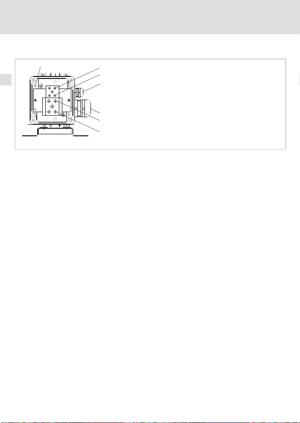
6 Installation électrique
Opérations de montage
Opérations de montage
PE
Ordre des opérations de raccordement de la résistance de freinage
1. Couper l’appareil de base du réseau et vérifier si toutes les bornes de puissance sont
hors tension.
2. Démonter le cache−bornier.
3. Connexion du câble de la résistance de freinage
– Pour les câbles d’une longueur jusqu’à 0.5 m, utiliser des câbles torsadés (voir
schéma de câblage, variante 1).
– Pour les câbles d’une longueur jusqu’à 5 m, utiliser des câbles blindés (voir schéma
de câblage, variante 2).
– Faire passer le câble par le presse−étoupe à vis .
– Connecter les fils sur les raccords RB1, RB2 et PE de la résistance de freinage. Tenir
compte du couple de serrage. Prévoir impérativement un raccordement PE selon
EN 61800−5−1.
– Serrer à fond le presse−étoupe à vis .
Lorsqu’un câble blindé est utilisé, relier le blindage à fond et par une surface
importante avec le presse−étoupe.
– Connecter les fils et le blindage sur l’appareil de base. Tenir compte de la
documentation de l’appareil de base.
4. Connexion des câbles du contact thermique
– Utiliser un câble torsadé.
– Faire passer le câble par le presse−étoupe à vis .
– Connecter les fils aux raccords T1 et T2 de la résistance de freinage. Tenir compte
du couple de serrage.
– Serrer à fond le presse−étoupe à vis .
– Intégrer le contact thermique dans la surveillance de l’installation de façon à ce
qu’en cas de surchauffe de la résistance de freinage, l’alimentation réseau soit
coupée.
5. Monter le cache−bornier.
1
0
T1
T2
RB1
RB2
ERBS103
78
EDKRBS047R DE/EN/FR/ES/IT 8.0
Page 79

Intervalles de maintenance
Maintenance
7 Maintenance
Intervalles de maintenance
La résistance ne nécessite aucun entretien. Cependant, il convient de procéder à des
contrôles visuels réguliers. Selon les conditions ambiantes, prévoir des intervalles de
contrôle suffisamment courts.
Vérifier
ƒ si les conditions ambiantes de la résistance de freinage correspondent toujours à
celles indiquées au chapitre Spécifications techniques ;
ƒ si des poussières ou dépôts éventuels risquent d’entraver la dissipation thermique de
la résistance de freinage ;
ƒ si les liaisons mécaniques et électriques sont correctes.
Opérations de maintenance
Nettoyage de la résistance de freinage
1. Couper l’appareil de base du réseau et attendre 3 minutes au minimum.
2. Vérifier la température de la résistance de freinage et laisser refroidir si nécessaire.
3. Vérifier si les raccords de la résistance de freinage sont hors tension.
4. Nettoyer la résistance de freinage (ne faire qu’un nettoyage à sec, sans agent
détergent).
7
EDKRBS047R DE/EN/FR/ES/IT 8.0
79
Page 80

7 Maintenance
Opérations de maintenance
80
EDKRBS047R DE/EN/FR/ES/IT 8.0
Page 81

Contenido i
1 Acerca de esta documentación 82 . . . . . . . . . . . . . . . . . . . . . . . . . . . . . . . . . . . . . . . .
Información sobre la validez 82 . . . . . . . . . . . . . . . . . . . . . . . . . . . . . . . . . . . . . . . . . .
Grupo objetivo 82 . . . . . . . . . . . . . . . . . . . . . . . . . . . . . . . . . . . . . . . . . . . . . . . . . . . .
Historia del documento 82 . . . . . . . . . . . . . . . . . . . . . . . . . . . . . . . . . . . . . . . . . . . . .
Convenciones utilizadas 83 . . . . . . . . . . . . . . . . . . . . . . . . . . . . . . . . . . . . . . . . . . . . .
Indicaciones utilizadas 84 . . . . . . . . . . . . . . . . . . . . . . . . . . . . . . . . . . . . . . . . . . . . . .
2 Instrucciones de seguridad 86 . . . . . . . . . . . . . . . . . . . . . . . . . . . . . . . . . . . . . . . . . . .
Instrucciones de seguridad generales 86 . . . . . . . . . . . . . . . . . . . . . . . . . . . . . . . . . .
Peligros residuales 87 . . . . . . . . . . . . . . . . . . . . . . . . . . . . . . . . . . . . . . . . . . . . . . . . . .
3 Descripción del producto 89 . . . . . . . . . . . . . . . . . . . . . . . . . . . . . . . . . . . . . . . . . . . .
Vista general 89 . . . . . . . . . . . . . . . . . . . . . . . . . . . . . . . . . . . . . . . . . . . . . . . . . . . . . .
Identificación 90 . . . . . . . . . . . . . . . . . . . . . . . . . . . . . . . . . . . . . . . . . . . . . . . . . . . . .
Uso previsto 91 . . . . . . . . . . . . . . . . . . . . . . . . . . . . . . . . . . . . . . . . . . . . . . . . . . . . . . .
Condiciones del dimensionado 92 . . . . . . . . . . . . . . . . . . . . . . . . . . . . . . . . . . . . . . .
4 Datos técnicos 94 . . . . . . . . . . . . . . . . . . . . . . . . . . . . . . . . . . . . . . . . . . . . . . . . . . . . .
Datos generales y condiciones de uso 94 . . . . . . . . . . . . . . . . . . . . . . . . . . . . . . . . .
Datos nominales 96 . . . . . . . . . . . . . . . . . . . . . . . . . . . . . . . . . . . . . . . . . . . . . . . . . . .
Datos mecánicos 98 . . . . . . . . . . . . . . . . . . . . . . . . . . . . . . . . . . . . . . . . . . . . . . . . . .
5 Instalación mecánica 100 . . . . . . . . . . . . . . . . . . . . . . . . . . . . . . . . . . . . . . . . . . . . . . . .
Espacio libre para el montaje 100 . . . . . . . . . . . . . . . . . . . . . . . . . . . . . . . . . . . . . . . . .
Pasos para el montaje 101 . . . . . . . . . . . . . . . . . . . . . . . . . . . . . . . . . . . . . . . . . . . . . . .
6 Instalación eléctrica 102 . . . . . . . . . . . . . . . . . . . . . . . . . . . . . . . . . . . . . . . . . . . . . . . .
Indicaciones importantes 102 . . . . . . . . . . . . . . . . . . . . . . . . . . . . . . . . . . . . . . . . . . . .
Datos de conexión 102 . . . . . . . . . . . . . . . . . . . . . . . . . . . . . . . . . . . . . . . . . . . . . . . . . .
Esquema de conexiones 103 . . . . . . . . . . . . . . . . . . . . . . . . . . . . . . . . . . . . . . . . . . . . .
Pasos para el montaje 104 . . . . . . . . . . . . . . . . . . . . . . . . . . . . . . . . . . . . . . . . . . . . . . .
7 Mantenimiento 105 . . . . . . . . . . . . . . . . . . . . . . . . . . . . . . . . . . . . . . . . . . . . . . . . . . . .
Intervalos de mantenimiento 105 . . . . . . . . . . . . . . . . . . . . . . . . . . . . . . . . . . . . . . . . .
Trabajos de mantenimiento 105 . . . . . . . . . . . . . . . . . . . . . . . . . . . . . . . . . . . . . . . . .
EDKRBS047R DE/EN/FR/ES/IT 8.0
81
Page 82

1 Acerca de esta documentación
Información sobre la validez
0Fig. 0Tab. 0
1 Acerca de esta documentación
Información sobre la validez
Este manual es válido para la resistencia de frenado
ƒ ERBS015R800W
ƒ ERBS015R01K2
ƒ ERBS015R02K4
ƒ ERBS018R800W
ƒ ERBS018R01K2
ƒ ERBS018R01K4
ƒ ERBS018R01K9
ƒ ERBS018R02K8
ƒ ERBS027R600W
ƒ ERBS027R01K2
ƒ ERBS027R01K4
ƒ ERBS047R400W
ƒ ERBS047R800W
Grupo objetivo
Esta documentación va dirigida a personal experto y cualificado según IEC 60364.
Personal experto cualificado son aquellas personas que disponen de las cualificaciones
adecuadas para realizar los trabajos necesarios para la instalación, montaje, puesta en
marcha y operación del producto.
¡Sugerencia!
Encontrará información y recursos sobre los productos de Lenze en el área de
descargas de
http://www.Lenze.com
Historia del documento
Número de material Versión Descripción
.@R_ 8.0 02/2011 TD29 Revisión
82
EDKRBS047R DE/EN/FR/ES/IT 8.0
Page 83

Acerca de esta documentación
Convenciones utilizadas
Convenciones utilizadas
Tipo de información Marcación Ejemplos/indicaciones
Escritura de números
Separación de decimales
Advertencias
Advertencias UL
Advertencias UR
Resalte del texto
Nombre del programa » « Software para PC
Símbolos
Referencia cruzada
Punto Por norma general se utiliza el punto
para los decimales.
Por ejemplo: 1234.56
Sólo se utilizan en idioma inglés.
Por ejemplo: »Engineer«, »Global
Drive Control« (GDC)
Referencia a otra página en la que se
encontrará información adicional.
Por ejemplo: 16 = véase la
página 16
1
EDKRBS047R DE/EN/FR/ES/IT 8.0
83
Page 84

1 Acerca de esta documentación
Indicaciones utilizadas
Indicaciones utilizadas
Para indicar peligros e información importante, se utilizan en esta documentación los
siguientes términos indicativos y símbolos:
Instrucciones de seguridad
Estructura de las instrucciones de seguridad:
¡Peligro!
(indican el tipo y la gravedad del peligro)
Texto indicativo
(describe el peligro y da instrucciones para evitarlo)
Pictograma y término indicativo Significado
Riesgo de daños personales por voltaje eléctrico
¡Peligro!
¡Peligro!
¡Alto!
Instrucciones de uso
Pictograma y término indicativo Significado
Indica un peligro inminente que puede causar la muerte o
lesiones graves si no se toman las medidas adecuadas.
Riesgo de daños personales por una fuente de riesgo
general
Indica un peligro inminente que puede causar la muerte o
lesiones graves si no se toman las medidas adecuadas.
Peligro de daños materiales
Indica un posible riesgo que puede ocasionar daños
materiales si no se toman las medidas adecuadas.
¡Aviso!
¡Sugerencia!
84
Nota importante para el funcionamiento sin fallos
Sugerencia útil para facilitar la operación
Referencia a otra documentación
EDKRBS047R DE/EN/FR/ES/IT 8.0
Page 85

Acerca de esta documentación
Instrucciones de seguridad y de uso especiales para UL y UR
Pictograma y término indicativo Significado
Instrucción de seguridad o de uso para la utilización de un
equipo con aprobación UL en instalaciones con
Warnings !
Warnings !
aprobación UL.
Posiblemente el sistema de accionamiento no funcionará
según UL si no se toman las medidas adecuadas.
Instrucción de seguridad o de uso para la utilización de un
equipo con aprobación UR en instalaciones con
aprobación UL.
Posiblemente el sistema de accionamiento no funcionará
según UL si no se toman las medidas adecuadas.
Indicaciones utilizadas
1
EDKRBS047R DE/EN/FR/ES/IT 8.0
85
Page 86

2 Instrucciones de seguridad
Instrucciones de seguridad generales
2 Instrucciones de seguridad
Instrucciones de seguridad generales
¡Peligro!
Si no se observan las siguientes instrucciones básicas de seguridad, pueden
ocasionarse serios daños a personas y materiales:
ƒ Los componentes de accionamiento y automatización de Lenze ...
... sólo deben utilizarse de la manera adecuada.
... nunca deben ponerse en funcionamiento si existen daños visibles.
... nunca deben someterse a modificaciones técnicas.
... nunca deben ponerse en funcionamiento si no están completamente montados.
... nunca deben ponerse en funcionamiento sin las cubiertas necesarias.
... pueden incluir durante el después del funcionamiento, y dependiendo de su grado de
protección, piezas vivas, así como móviles y giratorias. Las superficies pueden estar
calientes.
ƒ Observe todas las indicaciones de la documentación adjunta y la documentación
correspondiente.
Es requisito esencial para un funcionamiento seguro y sin fallos, así como para lograr las
características declaradas del producto.
Las indicaciones técnicas de procedimiento y secciones de conexión presentadas en
este documento son propuestas, cuya transferabilidad a la aplicación correspondiente
deberá ser comprobada. El fabricante no se hace responsable de la aptitud de los
procedimientos y propuestas de conexión que se indican.
ƒ Todos los trabajos con y en componentes de accionamiento y automatización de
Lenze sólo deben ser realizados por personal experto cualificado.
Según IEC 60364 o resp. CENELEC HD 384 se trata de personas, ...
... que conocen la instalación, el montaje, la puesta en marcha y la operación del
producto.
... que disponen de las cualificaciones correspondientes a su trabajo.
... que conocen y saben aplicar todas las normas de prevención de accidentes, directivas
y leyes aplicables en el lugar de uso.
86
EDKRBS047R DE/EN/FR/ES/IT 8.0
Page 87

Instrucciones de seguridad
Peligros residuales
Peligros residuales
¡Peligro!
Voltaje eléctrico peligroso
Durante el funcionamiento del equipo básico y hasta 3 minutos tras la
desconexión de la red las conexiones de la resistencia de frenado pueden
mantener una tensión peligrosa.
Posibles consecuencias:
ƒ Muerte o lesiones graves al entrar en contacto con los bornes de conexión.
Medidas de protección
ƒ Separar el equipo básico de la red antes de realizar cualquier trabajo en el
equipo básico.
ƒ Comprobar que no haya ningún borne de potencia con tensión.
ƒ Elegir el lugar de montaje de tal forma que siempre estén garantizadas las
condiciones de uso indicadas en los datos técnicos.
¡Peligro!
Superficie caliente durante el funcionamiento
La resistencia de frenado alcanza temperaturas muy altas durante el
funcionamiento. (Temperaturas, véanse datos técnicos).
Posibles consecuencias:
ƒ Fuertes quemaduras al tocar la resistencia de frenado.
ƒ Fuego o incendio sin llama si se encuentran materiales o sustancias
inflamables cerca de la resistencia de frenado o pueden acceder a ella.
Medidas de protección:
ƒ Antes de trabajar en la resistencia de frenado comprobar la temperatura de
la superficie.
ƒ Elegir el lugar de montaje de forma que las condiciones de uso indicadas en
los datos técnicos siempre estén garantizadas.
ƒ Asegurar el lugar de montaje mediante medidas de protección de
incendios y protección contra el contacto.
2
EDKRBS047R DE/EN/FR/ES/IT 8.0
87
Page 88

2 Instrucciones de seguridad
Peligros residuales
Warnings !
Conditions of Acceptability:
ƒ The products covered by this report are intended for use with Power
Conversion Equipment (drives) only.
ƒ The Temperature Switch must be connected to the drive, so that the drive
switches off in case when the maximum operating temperature is
exceeded.
ƒ Temperature tests and abnormal operation tests have only been
conducted for single resistive elements and for continuous duty as
indicated under RATINGS. For any grouping of the resistor elements an
additional temperature test must be conducted, depending on the
evaluation of the mechanical construction and the expected temperature
rise.
ƒ For any duty cycle operation in the end−use application it must be
guaranteed that the maximum Wattage rating will not be exceeded. This
may be evaluated by calculation. If there will be any concern regarding to
this, additional temperature tests have to be conducted under end−use
conditions.
88
EDKRBS047R DE/EN/FR/ES/IT 8.0
Page 89

3 Descripción del producto
Vista general
Contenido del suministro
Pos. Descripción
Resistencia de frenado
Instrucciones para el montaje
Elementos de la resistencia de frenado
Pos. Descripción
Placa de características
Caja de bornes
Prensaestopas cable de termocontacto
Prensaestopas cable de resistencia de frenado
Advertencia
Ángulo de fijación
Descripción del producto
Vista general
3
ERBS101
EDKRBS047R DE/EN/FR/ES/IT 8.0
89
Page 90

3 Descripción del producto
Identificación
Identificación
Código de tipo ERBx xxxx xxxx
Serie de productos
Resistencia RB [W]
p.ej.
470R = 470
W
075D = 7.5 W
Potencia constante Pd [W]
p.ej. 120W = 120 W
01K2 = 1.2 kW
ERBS104
90
EDKRBS047R DE/EN/FR/ES/IT 8.0
Page 91

Descripción del producto
Uso previsto
Uso previsto
Las resistencias de frenado
ƒ sólo deberán utilizarse en las condiciones de uso descritas en este manual.
ƒ son componentes
– para ser montados en una máquina.
– para ser unidos a otros componentes y crear una máquina.
La puesta en marcha de la resistencia de frenado está prohibida hasta que se haya
constatado que la máquina en la que se montará la resistencia de frenado cumple con
las exigencias de la Directiva de Máquinas CE.
ƒ son medios de trabajo electrónicos para ser montados en armarios eléctricos o en
recintos de trabajo cerrados.
ƒ cumplen con las exigencias de protección de la Directiva CE "Bajo Voltaje".
ƒ no son máquinas en el sentido de la Directiva CE de Máquinas.
ƒ no son electrodomésticos sino que han sido previstos exclusivamente como
componentes para ser utilizados para fines industriales.
Sistemas de accionamiento con resistencias de frenado
ƒ La responsabilidad del cumplimiento con las Directivas CE en la aplicación de la
máquina es del usuario.
¡Cualquier otro uso se considerará inadecuado!
3
EDKRBS047R DE/EN/FR/ES/IT 8.0
91
Page 92

3 Descripción del producto
Condiciones del dimensionado
Condiciones del dimensionado
Al utilizar resistencias de frenado observe lo siguiente:
ƒ Valor promedio de la potencia en modo generador < potencia constante P
resistencia de frenado.
ƒ Potencia en modo generador durante el tiempo de frenado < cantidad térmica Q
la resistencia de frenado.
ƒ Tiempo de frenado < 10 % del tiempo de ciclo (tiempo de frenado + tiempo de
descanso).
ƒ Conectar siempre el termocontacto para incluirlo así en la monitorización de la
instalación, de manera que en caso de sobrecalentamiento de la resistencia de
frenado, se desconecte el suministro de red del equipo básico.
En ese momento debe valer: En el intervalo de tiempo t
los tiempos de frenado acumulados t
brk,máx
.
frenado t
siempre deben ser £ que la duración máxima de
brk
(ciclo de resistencia de frenado)
cyc,RB
Cálculo
Ciclo de resistencia de frenado t
Q
t
cyc,RB
Q
B
P
d
B
+
con
P
d
Cantidad térmica en Ws
Potencia constante en W
Duración máx. de frenado t
@ R
Q
B
t
brk,max
Q
B
R
B
U
máx
+
Cantidad térmica en Ws
Resistencia en W
Voltaje operativo máx. en V
B
con
2
U
max
:
cyc,RB
dentro del intervalo de tiempo t
brk,máx
cyc,RB
Ejemplos para la evaluación de la condición
Se conoce el ciclo de la resistencia de frenado t
= 10 s. Los tiempos de frenado t
t
brk,máx
brk
= 150 s y la duración máx. de frenado
cyc,RB
y el ciclo de proceso t
cyc,Prc
de la
d
:
son ejemplos.
de
B
92
EDKRBS047R DE/EN/FR/ES/IT 8.0
Page 93

Descripción del producto
£
£
£
£
³
£
Condiciones del dimensionado
3
0.5 0.5
1
1
ü
0.5 0.5
1
ü
ü
0.5 0.5
1
= 6.5 s
brk brk,max
tt
S
= 150 s
cyc,RB
t
En el ejemplo anterior se mantiene la condición de dimensionado en todo momento. En el
siguiente ejemplo las condiciones de dimensionado no se mantienen una vez, es decir que
la resistencia de frenado seleccionada no es adecuada para el proceso predeterminado.
Utilice una resistencia de frenado con mayor potencia (menor ciclo de resistencia de frenado
).
t
cyc,RB
= 6.5 s
brk brk,max
tt
S
0.5 0.5
0.5 0.5
1 1
[s]
brk
t
= 7 s
tt
S
1 11
û
ü
ü
brk brk,max
= 11 s
1 1
brk brk,max
tt
S
= 10 s
brk brk,max
tt
S
1 1
11111
1 1
1010 5050 100100 200200150150
t [s]
[s]
brk
t
cyc,Prs
t
û
cyc,Prs
t
cyc,Prs
t
ü
= 10 s
cyc,Prs
t
brk brk,max
tt
S
cyc,Prs
t
1010 5050 100100 200200150150
t [s]
EDKRBS047R DE/EN/FR/ES/IT 8.0
93
Page 94

4 Datos técnicos
Datos generales y condiciones de uso
4 Datos técnicos
Datos generales y condiciones de uso
Conformidad y aprobación
Conformidad
CE
Aprobación
UR UL508 Industrial Control Equipment, Underwriter
Protección personal y de equipos
Tipo de protección
Termocontacto
Versión NC, 230 °C
Potencia de ruptura 250 V AC / 5 A
2006/95/CE Directiva de Bajo Voltaje
Laboratories (File−No. E208678) for USA and Canada
EN 60529
NEMA 250 Protección contra el contacto según tipo 4
IP65
Condiciones ambientales
Clima
Almacenaje IEC/EN 60721−3−1 1K3 (−25 ... +60 °C)
Transporte IEC/EN 60721−3−2 2K3 (−25 ... +70 °C)
Operación IEC/EN 60721−3−3 3K3 (−10 ... +55 °C)
Altura de montaje 0 ... 4000 m snm
Resistencia a las
sacudidas
(9.81 m/s2 = 1 g)
EN 50178,
IEC 61800−5−1,
Germanischer
Loyd, condiciones
generales
Reducción de corriente de +45 ... +55 °C: 2.5 %/°C
1000 ... 4000 m snm: Reducción de corriente
5 %/1000 m
Resistente a las aceleraciones hasta 1 g
94
EDKRBS047R DE/EN/FR/ES/IT 8.0
Page 95

Datos generales y condiciones de uso
Datos técnicos
Condiciones de montaje
Lugar de montaje
Posición de montaje
Estándar Colgado vertical con conexiones hacia abajo
Variante De pie, horizontal, con ángulo de sujeción abajo
Espacios libres para el
montaje
Estándar 100
Variante 101
l El lugar de montaje debe cumplir con las
características del equipo indicadas en los "Datos
generales".
l No deben encontrarse materiales o sustancias
inflamables cerca de la resistencia de frenado.
l El calor generado por la resistencia de frenado debe
eliminarse sin obstáculos.
4
EDKRBS047R DE/EN/FR/ES/IT 8.0
95
Page 96

4 Datos técnicos
Datos nominales
Datos nominales
Datos eléctricos
R
B
[W]
ERBS015R800W
ERBS015R01K2 1200 180
ERBS015R02K4 2400 420
ERBS018R800W
ERBS018R01K2 1200 180
ERBS018R01K4 1400 210
ERBS018R01K9 1900 285
ERBS018R02K8 2800 420
ERBS027R600W
ERBS027R01K2 1200 180
ERBS027R01K4 1400 210
ERBS047R400W
ERBS047R800W 800 120
R
B
P
d
Q
B
U
máx
Resistencia
Potencia constante
Cantidad térmica
Voltaje operativo máx.
15
18
27
47
P
d
[W] [kWs] [VDC]
800 120
800 120
600 90
400 60
Q
B
U
max
800
96
EDKRBS047R DE/EN/FR/ES/IT 8.0
Page 97

Datos técnicos
Datos nominales
Temperaturas
T
nom
en la superficie 250 400 1000
en el límite del
espacio libre para el
*)
montaje
T
nom
T
TK
T
máx
*) Medido en el aire (pequeño coeficiente de conductividad térmica); cuando se
Temperatura máxima con datos nominales
Temperatura a la cual se activa el termocontacto
Temperatura máxima en caso de uso indebido
encuentran materiales/sustancias en el límite del espacio libre para el montaje, que
podrían calentarse (alto coeficiente de conductividad térmica) la temperatura sigue
incrementándose.
120 200 300
T
[°C]
TK
4
T
máx
EDKRBS047R DE/EN/FR/ES/IT 8.0
97
Page 98

4 Datos técnicos
Datos mecánicos
Datos mecánicos
Formato 1
a b c1 c3 c4 c5 d3 e e1 g1
[mm] [kg]
ERBS015R800W 710
ERBS015R01K2 1020 841 5.6
ERBS018R800W 710 531 4.0
ERBS018R01K2 1020 841 5.6
ERBS018R01K4 1110 931 6.3
ERBS027R600W 550 371 3.1
ERBS027R01K2 1020 841 5.6
ERBS027R01K4 1110 931 6.3
ERBS047R400W 400 221 2.3
ERBS047R800W 710 531 4.0
105 155.5 48
531
45 90 114 110 6.2
ERBS102
4.0
98
EDKRBS047R DE/EN/FR/ES/IT 8.0
Page 99

Formato 2
ERBS015R02K4 1020
ERBS018R01K9 825
ERBS018R02K8 1110
Datos técnicos
Datos mecánicos
a b c1 c3 c4 c5 d3 e e1 g1
[mm] [mm] [kg]
841
105 155.5 48
646
45 180 204 200 6.2
931
4
ERBS107
10.0
8.7
12.0
EDKRBS047R DE/EN/FR/ES/IT 8.0
99
Page 100

5 Instalación mecánica
Espacio libre para el montaje
5 Instalación mecánica
Espacio libre para el montaje
Espacios libres para el montaje estándar
x Espacio libre para el cableado
y Radio de flexión del cable
Todas las medidas en milímetros
100
ERBS106
EDKRBS047R DE/EN/FR/ES/IT 8.0
 Loading...