

Page 1
EDK94AZMP45
.P>2
L−force Drives
Montageanleitung
Mounting Instructions
Instructions de montage
Ä.P>2ä
9400 82 ... 200 A
E94AZMP0824, E94AZMP2004
Instrucciones para el montaje
Istruzioni per il montaggio
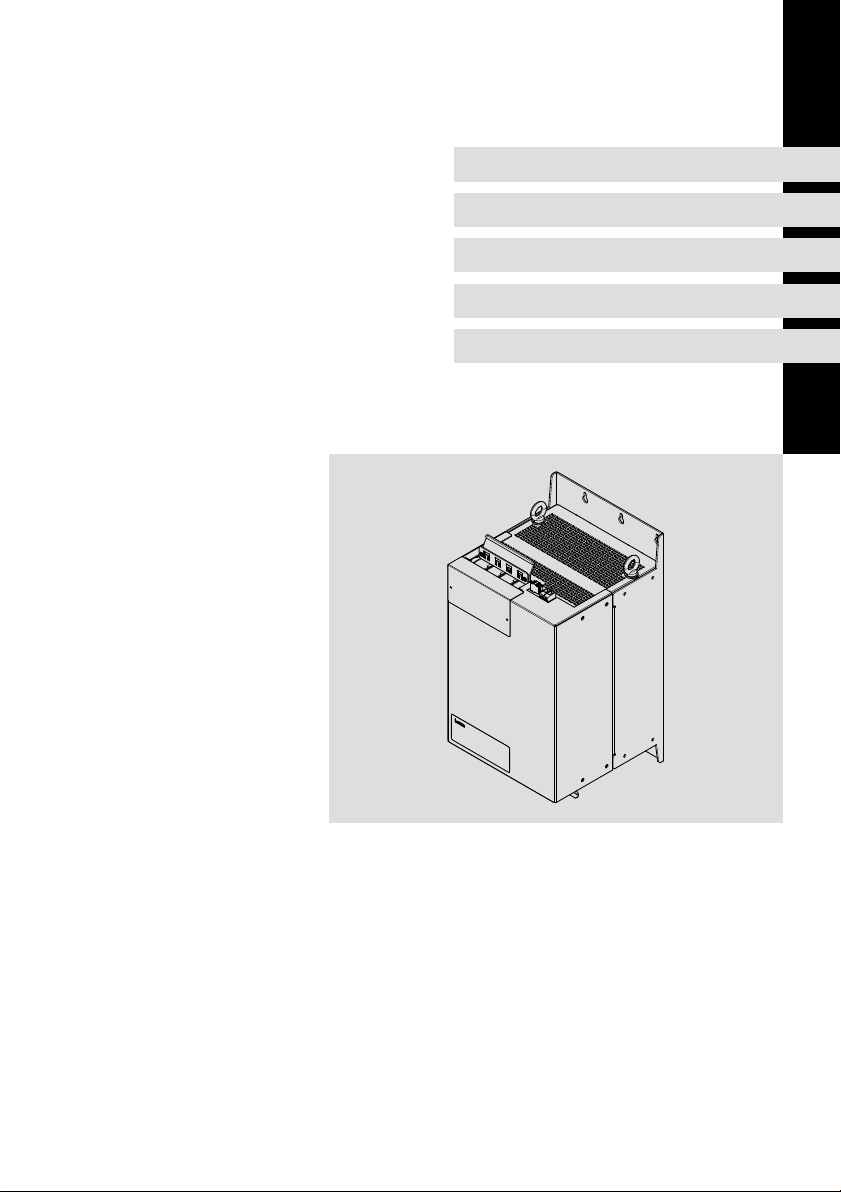
Netzfilter
Mains filter
Filtre réseau
Filtro de red
Filtro di rete
Page 2

Lesen Sie zuerst diese Anleitung und die Dokumentation zum
Grundgerät, bevor Sie mit den Arbeiten beginnen!
Beachten Sie die enthaltenen Sicherheitshinweise.
Please read these instructions and the documentation of the standard
device before you start working!
Observe the safety instructions given therein!
Lire le présent fascicule et la documentation relative à l’appareil de base
avant toute manipulation de l’équipement !
Respecter les consignes de sécurité fournies.
Lea estas instrucciones y la documentación del equipo básico antes de
empezar a trabajar.
Observe las instrucciones de seguridad indicadas.
Prima di iniziare qualsiasi intervento, leggere le presenti istruzioni e la
documentazione relativa al dispositivo di base.
Osservare le note di sicurezza.
Page 3

Inhalt i
1 Über diese Dokumentation 4. . . . . . . . . . . . . . . . . . . . . . . . . . . . . . . . . . . . . . . . .
1.1 Informationen zur Gültigkeit 4. . . . . . . . . . . . . . . . . . . . . . . . . . . . . . . . .
1.2 Zielgruppe 4. . . . . . . . . . . . . . . . . . . . . . . . . . . . . . . . . . . . . . . . . . . . . . . .
1.3 Dokumenthistorie 5. . . . . . . . . . . . . . . . . . . . . . . . . . . . . . . . . . . . . . . . . .
1.4 Verwendete Konventionen 5. . . . . . . . . . . . . . . . . . . . . . . . . . . . . . . . . . .
1.5 Verwendete Hinweise 6. . . . . . . . . . . . . . . . . . . . . . . . . . . . . . . . . . . . . . .
2 Sicherheitshinweise 8. . . . . . . . . . . . . . . . . . . . . . . . . . . . . . . . . . . . . . . . . . . . . . .
2.1 Allgemeine Sicherheitshinweise 8. . . . . . . . . . . . . . . . . . . . . . . . . . . . . .
2.2 Restgefahren 9. . . . . . . . . . . . . . . . . . . . . . . . . . . . . . . . . . . . . . . . . . . . . .
3 Produktbeschreibung 11. . . . . . . . . . . . . . . . . . . . . . . . . . . . . . . . . . . . . . . . . . . . .
3.1 Lieferumfang 11. . . . . . . . . . . . . . . . . . . . . . . . . . . . . . . . . . . . . . . . . . . . . .
3.2 Übersicht 11. . . . . . . . . . . . . . . . . . . . . . . . . . . . . . . . . . . . . . . . . . . . . . . . .
3.3 Identifikation 12. . . . . . . . . . . . . . . . . . . . . . . . . . . . . . . . . . . . . . . . . . . . . .
3.4 Einsatzbedingungen 12. . . . . . . . . . . . . . . . . . . . . . . . . . . . . . . . . . . . . . . .
4 Technische Daten 13. . . . . . . . . . . . . . . . . . . . . . . . . . . . . . . . . . . . . . . . . . . . . . . . .
4.1 Allgemeine Daten und Einsatzbedingungen 13. . . . . . . . . . . . . . . . . . . .
4.2 Bemessungsdaten 15. . . . . . . . . . . . . . . . . . . . . . . . . . . . . . . . . . . . . . . . . .
4.3 Mechanische Daten 16. . . . . . . . . . . . . . . . . . . . . . . . . . . . . . . . . . . . . . . .
5 Mechanische Installation 18. . . . . . . . . . . . . . . . . . . . . . . . . . . . . . . . . . . . . . . . . . .
5.1 Wichtige Hinweise 18. . . . . . . . . . . . . . . . . . . . . . . . . . . . . . . . . . . . . . . . . .
5.2 Anordnung der Geräte 19. . . . . . . . . . . . . . . . . . . . . . . . . . . . . . . . . . . . . . .
5.3 Befestigungsraster 21. . . . . . . . . . . . . . . . . . . . . . . . . . . . . . . . . . . . . . . . . .
5.4 Montageschritte 22. . . . . . . . . . . . . . . . . . . . . . . . . . . . . . . . . . . . . . . . . . .
6 Elektrische Installation 24. . . . . . . . . . . . . . . . . . . . . . . . . . . . . . . . . . . . . . . . . . . . .
6.1 Wichtige Hinweise 24. . . . . . . . . . . . . . . . . . . . . . . . . . . . . . . . . . . . . . . . . .
6.2 Anschlussplan 27. . . . . . . . . . . . . . . . . . . . . . . . . . . . . . . . . . . . . . . . . . . . .
6.3 Anschlussdaten 29. . . . . . . . . . . . . . . . . . . . . . . . . . . . . . . . . . . . . . . . . . . .
6.4 Montageschritte 31. . . . . . . . . . . . . . . . . . . . . . . . . . . . . . . . . . . . . . . . . . .
EDK94AZMP45 DE/EN/FR/ES/IT 7.0
3
Page 4

1
Über diese Dokumentation
Informationen zur Gültigkeit
1 Über diese Dokumentation
0Abb. 0Tab. 0
1.1 Informationen zur Gültigkeit
Diese Anleitung ist gültig für
ƒ Netzfilter E94AZMP0824
ƒ Netzfilter E94AZMP2004
1.2 Zielgruppe
Diese Dokumentation richtet sich an qualifiziertes Fachpersonal nach
IEC 60364.
Qualifiziertes Fachpersonal sind Personen, die für die auszuführenden Tätigkeiten bei der Aufstellung, Montage, Inbetriebsetzung und dem Betrieb des Produkts über entsprechende Qualifikationen verfügen.
Tipp!
Informationen und Hilfsmittel rund um die Lenze−Produkte finden
Sie im Download−Bereich unter
www.lenze.com
4
EDK94AZMP45 DE/EN/FR/ES/IT 7.0
Page 5
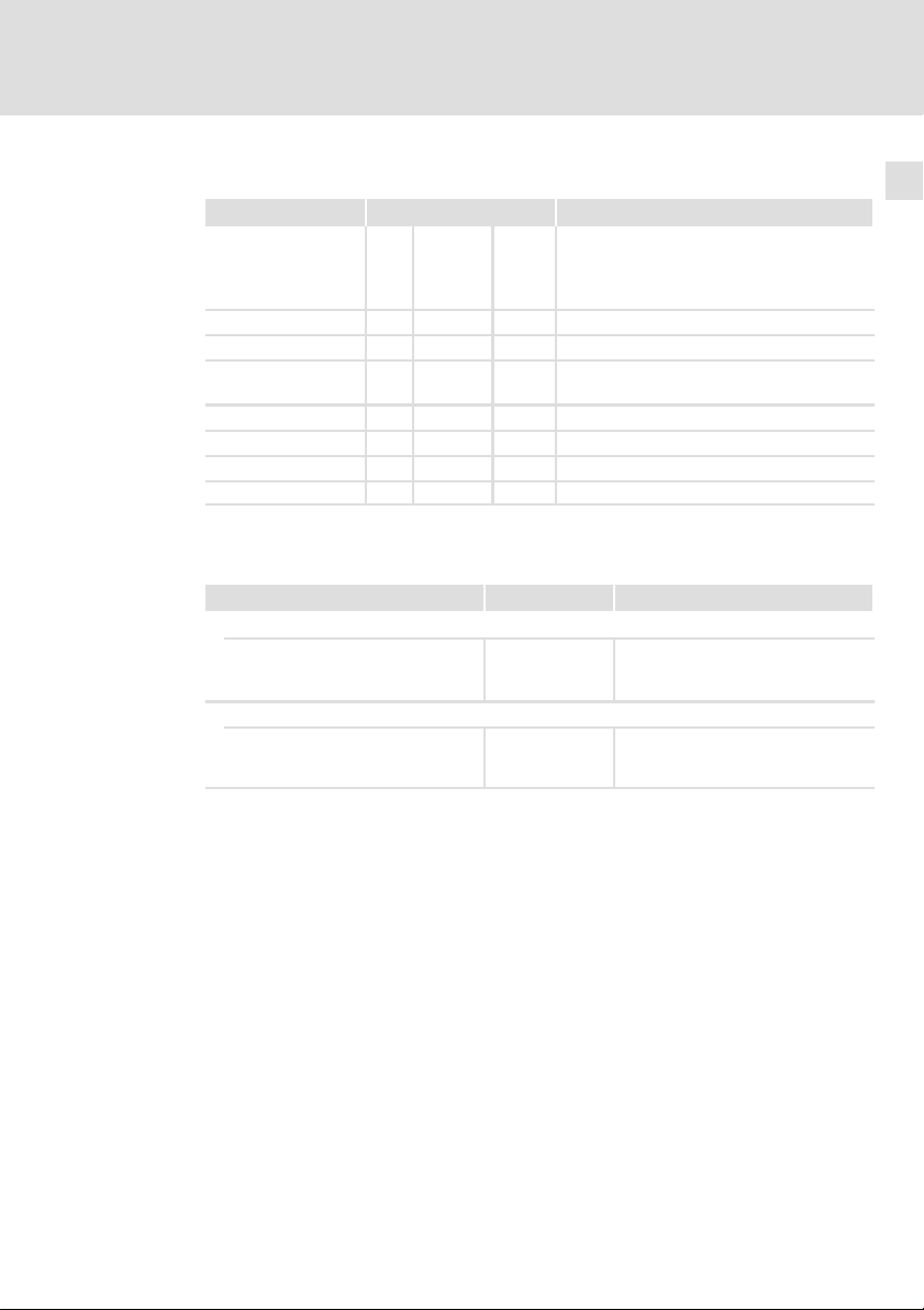
1.3 Dokumenthistorie
Materialnummer Version Beschreibung
.P>2 7.0 09/2014 TD29 UL−Hinweise in französischer Sprache für
.M.: 6.0 10/2013 TD15 Ergänzungen i700
.BSñ 5.0 04/2010 TD29 Layout−Anpassung und Überarbeitung
.=)| 4.0 01/2009 TD29 Neuauflage wegen Neuorganisation des Un-
.8gd 3.0 02/2008 TD29 Überarbeitung
.6@N 2.0 06/2007 TD29 Überarbeitung
.5b# 1.1 04/2007 TD29 Erstausgabe, 5−sprachig
.5b# 1.0 04/2007 TD29 Erstausgabe, deutsch
1.4 Verwendete Konventionen
Informationsart Auszeichnung Beispiele/Hinweise
Zahlenschreibweise
Dezimaltrennzeichen
Textauszeichnung
Programmname » « PC−Software
Über diese Dokumentation
Dokumenthistorie
Canada
EAC−Konformität
allgemeine Korrekturen
ternehmens
Punkt Es wird generell der Dezimalpunkt
verwendet.
Zum Beispiel: 1234.56
Zum Beispiel: »Engineer«, »Global
Drive Control« (GDC)
1
EDK94AZMP45 DE/EN/FR/ES/IT 7.0
5
Page 6

1
Über diese Dokumentation
Verwendete Hinweise
1.5 Verwendete Hinweise
Um auf Gefahren und wichtige Informationen hinzuweisen, werden in dieser
Dokumentation folgende Piktogramme und Signalwörter verwendet:
Sicherheitshinweise
Aufbau der Sicherheitshinweise:
Gefahr!
(kennzeichnet die Art und die Schwere der Gefahr)
Hinweistext
(beschreibt die Gefahr und gibt Hinweise, wie sie vermieden werden
kann)
Piktogramm und Signalwort Bedeutung
Gefahr!
Gefahr!
Stop!
Anwendungshinweise
Gefahr von Personenschäden durch gefährliche elektrische Spannung
Hinweis auf eine unmittelbar drohende Gefahr, die den
Tod oder schwere Verletzungen zur Folge haben kann,
wenn nicht die entsprechenden Maßnahmen getroffen
werden.
Gefahr von Personenschäden durch eine allgemeine
Gefahrenquelle
Hinweis auf eine unmittelbar drohende Gefahr, die den
Tod oder schwere Verletzungen zur Folge haben kann,
wenn nicht die entsprechenden Maßnahmen getroffen
werden.
Gefahr von Sachschäden
Hinweis auf eine mögliche Gefahr, die Sachschäden zur
Folge haben kann, wenn nicht die entsprechenden Maßnahmen getroffen werden.
Piktogramm und Signalwort Bedeutung
Hinweis!
Tipp!
6
Wichtiger Hinweis für die störungsfreie Funktion
Nützlicher Tipp für die einfache Handhabung
Verweis auf andere Dokumentation
EDK94AZMP45 DE/EN/FR/ES/IT 7.0
Page 7

Über diese Dokumentation
Verwendete Hinweise
Spezielle Sicherheitshinweise und Anwendungshinweise
Piktogramm und Signalwort Bedeutung
1
Warnings!
Warnings!
Sicherheitshinweis oder Anwendungshinweis für den
Betrieb nach UL− oder CSA−Anforderungen.
Die Maßnahmen sind erforderlich, um die Anforderungen nach UL oder CSA zu erfüllen.
EDK94AZMP45 DE/EN/FR/ES/IT 7.0
7
Page 8

2
Sicherheitshinweise
Allgemeine Sicherheitshinweise
2 Sicherheitshinweise
2.1 Allgemeine Sicherheitshinweise
Gefahr!
Wenn Sie die folgenden grundlegenden Sicherheitsmaßnahmen
missachten, kann dies zu schweren Personenschäden und
Sachschäden führen:
ƒ Lenze−Antriebs− und Automatisierungskomponenten ...
... ausschließlich bestimmungsgemäß verwenden.
... niemals trotz erkennbarer Schäden in Betrieb nehmen.
... niemals technisch verändern.
... niemals unvollständig montiert in Betrieb nehmen.
... niemals ohne erforderliche Abdeckungen betreiben.
... können während und nach dem Betrieb − ihrer Schutzart entsprechend −
spannungsführende, auch bewegliche oder rotierende Teile haben. Oberflächen können heiß sein.
ƒ Alle Vorgaben der beiliegenden und zugehörigen Dokumentation
beachten.
Dies ist Voraussetzung für einen sicheren und störungsfreien Betrieb sowie
für das Erreichen der angegebenen Produkteigenschaften.
Die in diesem Dokument dargestellten verfahrenstechnischen Hinweise
und Schaltungsausschnitte sind Vorschläge, deren Übertragbarkeit auf die
jeweilige Anwendung überprüft werden muss. Für die Eignung der angegebenen Verfahren und Schaltungsvorschläge übernimmt der Hersteller keine
Gewähr.
ƒ Alle Arbeiten mit und an Lenze−Antriebs− und
Automatisierungskomponenten darf nur qualifiziertes Fachpersonal
ausführen.
Nach IEC 60364 bzw. CENELEC HD 384 sind dies Personen, ...
... die mit Aufstellung, Montage, Inbetriebsetzung und Betrieb des Produkts
vertraut sind.
... die über die entsprechenden Qualifikationen für ihre Tätigkeit verfügen.
... die alle am Einsatzort geltenden Unfallverhütungsvorschriften, Richtli-
nien und Gesetze kennen und anwenden können.
8
EDK94AZMP45 DE/EN/FR/ES/IT 7.0
Page 9

Sicherheitshinweise
Restgefahren
2
2.2 Restgefahren
Gefahr!
Gefährliche elektrische Spannung
Alle Leistungsanschlüsse führen bis zu 3 Minuten nach
Netz−Ausschalten gefährliche elektrische Spannung.
Mögliche Folgen:
ƒ Tod oder schwere Verletzungen beim Berühren der
Leistungsanschlüsse.
Schutzmaßnahmen:
ƒ Vor Arbeiten an den Leistungsanschlüssen Netz abschalten und
mindestens 3 Minuten warten.
ƒ Prüfen, ob alle Leistungsanschlüsse spannungsfrei sind.
Warnings!
Conditions of Acceptability:
ƒ The products covered by this report are only intended for use
with Power Conversion Equipment (inverters).
ƒ Consideration shall be given to the field wiring leads. No strain
relief test was performed on the leads.
ƒ The devices in this report are only evaluated for factory wiring
use.
ƒ Temperature tests were performed with hook mounted drive.
EDK94AZMP45 DE/EN/FR/ES/IT 7.0
9
Page 10

2
Sicherheitshinweise
Restgefahren
Stop!
Hohes Gerätegewicht
Das Gerät ist sehr schwer und muss für die Montage angehoben
werden.
Mögliche Folgen:
ƒ Personenschäden, insbesondere Rückenschäden beim Anheben
bzw. Halten des Gerätes
ƒ Sach− und Personenschäden durch Herunterfallen des Gerätes
Schutzmaßnahmen:
ƒ Gerät nur mit einer für das Gerätegewicht zugelassenen
Lastaufnahmeeinrichtung (z. B. Hallenkran) transportieren.
ƒ Hebezeug, Lastaufnahmeeinrichtung und Anschlagmittel vor
dem Transport auf ausreichende Tragfähigkeit und
einwandfreien Zustand prüfen.
ƒ Hebezeug und Anschlagmittel erst entfernen, wenn das Gerät
sicher auf einem tragfähigen Untergrund aufliegt oder endgültig
montiert ist.
10
EDK94AZMP45 DE/EN/FR/ES/IT 7.0
Page 11
3 Produktbeschreibung
3.1 Lieferumfang
Pos. Beschreibung
Netzfilter E94AZMPxxxx
Montageanleitung
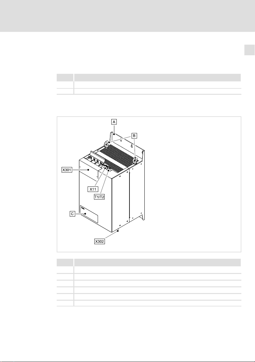
3.2 Übersicht
Produktbeschreibung
Lieferumfang
3
Pos. Beschreibung
X301 Netzanschluss L1 ... L3 und PE
X302 Anschlussleitungen zum DC Versorgungsmodul L1’ ... L3’ und PE
X11 Spannungsversorgung interner Lüfter (24 V DC)
T1/T2 Thermokontakt−Anschlussklemmen T1, T2
Transportösen
Typenschild
EDK94AZMP45 DE/EN/FR/ES/IT 7.0
SSP94NF301
11
Page 12
3
Produktbeschreibung
Identifikation
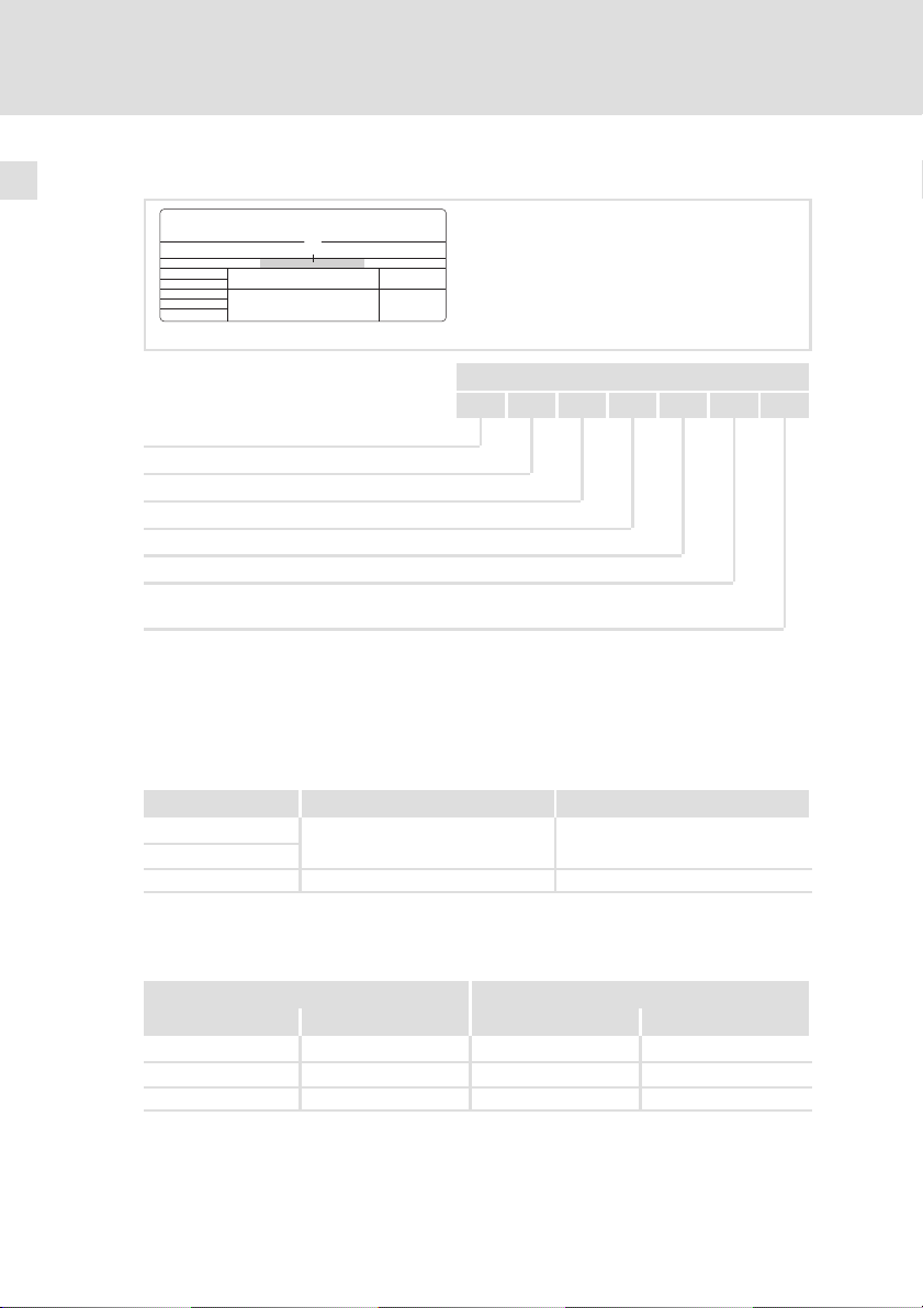
3.3 Identifikation
L
Type:
Typenschlüssel E94 A Z M P xxx x
Produktreihe
Gerätegeneration
Zubehör
Typ Netzfilter
für 9400 Power Supply
Bemessungsstrom [A]
Spannungsklasse
4 = 230 ... 400/500 V
SSP94NF002
3.4 Einsatzbedingungen
Die Verwendung dieses Filters ist zulässig mit Geräten der Produktreihe 9400
und i700 ab der Typenschildbezeichnung:
E94APNE1004
E94APNE2454
E70ACPSx0604x Vx ˘
Zuordnung Filter ˘ Grundgerät
Netzfilter DC Versorgungsmodul
Typ Gerätegröße Typ Gerätegröße
E94AZMP0824 4 E94APNE1004 4
E94AZMP2004 5 E94APNE2454 5
E94AZMP0824 4 E70ACPSx0604x 2
12
HW SW
VA
EDK94AZMP45 DE/EN/FR/ES/IT 7.0
˘
Page 13
Allgemeine Daten und Einsatzbedingungen
4 Technische Daten
4.1 Allgemeine Daten und Einsatzbedingungen
Konformität und Approbation
Approbation
UR
EAC TP TC 020/2011
EAC TP TC 004/2011
Angaben zu Netzen
Netzformen
Mit geerdetem Y−Punkt (TT−/TN−Netze)
Andere Netzformen Anweisungen über besondere Maßnahmen in der
UL508 Industrial Control Equipment, Underwriter Laborato-
(TR ZU 020/2011)
(TR ZU 004/2011)
ries (File−No. E219022) for USA and Canada
Elektromagnetische
Verträglichkeit von
technischen Erzeugnissen
Über die Sicherheit
von Niederspannungsausrüstung
Betrieb uneingeschränkt erlaubt
Dokumentation zum Grundgerät beachten!
Technische Daten
Eurasische Konformität
TR ZU: Technische Regulierung der Zollunion
Eurasische Konformität
TR ZU: Technische Regulierung der Zollunion
4
Personenschutz und Geräteschutz
Schutzart
Erdableitstrom IEC/EN 61800−5−1 > 3.5 mA AC
Isolationsfestigkeit IEC/EN 61800−5−1
EDK94AZMP45 DE/EN/FR/ES/IT 7.0
EN 60529 IP20
NEMA 250 Berührschutz nach
Typ 1
> 10 mA DC
< 2000 m Aufstellhöhe: Überspannungskategorie III
> 2000 m Aufstellhöhe: Überspannungskategorie II
Nicht im Anschlussbereich
der Klemmen
Bestimmungen und Sicherheitshinweise beachten!
13
Page 14
4
Technische Daten
Allgemeine Daten und Einsatzbedingungen
Umweltbedingungen
Klima
Lagerung
Transport IEC/EN 60721−3−2 2K3 (−25 ... +70 °C)
Betrieb IEC/EN 60721−3−3 3K3 (−10 ... +55 °C)
Aufstellhöhe 0 ... 4000 m üNN
Verschmutzung EN 61800−5−1 Verschmutzungsgrad 2
Rüttelfestigkeit (9,81 m/s
Transport
Betrieb
Montagebedingungen
Einbauort
Einbaulage Vertikal
Einbaufreiräume Die Einbaufreiräume ergeben sich aus der Montage-
Montageposition
Standard Nebenbau; Filter wird ohne Abstand links neben das
Variante Überbau; Filter wird über das Grundgerät geschraubt
IEC/EN 60721−3−1 1K3 (−25 ... +60 °C)
Stromreduzierung von +45 ... +55 °C: 2.5 %/°C
1000 ... 4000 m üNN: Stromreduzierung 5 %/1000 m
2
= 1 g)
IEC/EN 60721−3−2 2M2
EN 61800−2
Germanischer
Lloyd
IEC/EN 60068−2−6
2 ... 9 Hz: Amplitude 3.5 mm
10 ... 200 Hz: beschleunigungsfest bis 10 m/s
200 ... 500 Hz: beschleunigungsfest bis 15 m/s
5 ... 13.2 Hz: Amplitude ±1 mm
13.2 ... 100 Hz: beschleunigungsfest bis 0.7 g
10 ... 57 Hz: Amplitude 0.075 mm
57 ... 150 Hz: beschleunigungsfest bis 1 g
Im Schaltschrank
position und den Vorgaben des Grundgerätes.
Grundgerät geschraubt ( Mechanische Installation)
( Mechanische Installation)
2
2
14
EDK94AZMP45 DE/EN/FR/ES/IT 7.0
Page 15

Technische Daten
Bemessungsdaten
4
4.2 Bemessungsdaten
Netz Spannung Spannungsbereich Frequenzbereich
3/PE AC 230 180 − 0 % ... 264 + 0 % 45 − 0 % ... 65 + 0 %
3/PE AC 400 320 − 0 % ... 440 + 0 % 45 − 0 % ... 65 + 0 %
3/PE AC 500 400 − 0 % ... 550 + 0 % 45 − 0 % ... 65 + 0 %
E94AZMP0824 230/400/500 50/60 82/82/82 61/61/61 3
E94AZMP2004 230/400/500 50/60 200/200/200 150/150/150 3
E94AZMP0824
E94AZMP0824 200 0.25 6.4
E94AZMP2004 350 0.10 6.3
2)
Temperatur im Schaltschrank
2)
bei Montage für i700: Netzanschluss unten, Ausgang oben
Thermokontakt
E94AZMP0824
E94AZMP2004
U
[V] U
LN
Spannung Freq. Strom [A] Strom [A]
[V] [Hz] max. +45° C max. +55° C
400/500 50/60 49/49 30.6/30.6 3
Verlustleistung Induktivität Spannungsabfall
PV [W] L [mH] DU [V]
Ausführung max. Schaltspannung max. Schaltstrom
Öffner, 150 °C
[V] f [Hz]
LN
UTh [V AC] ITh [A]
250 2.5
Phasen-
zahl
Lüfter
E94AZMP0824
E94AZMP2004
EDK94AZMP45 DE/EN/FR/ES/IT 7.0
Spannung Strom
[V DC] [A]
24
0.3
15
Page 16
4
Technische Daten
Mechanische Daten
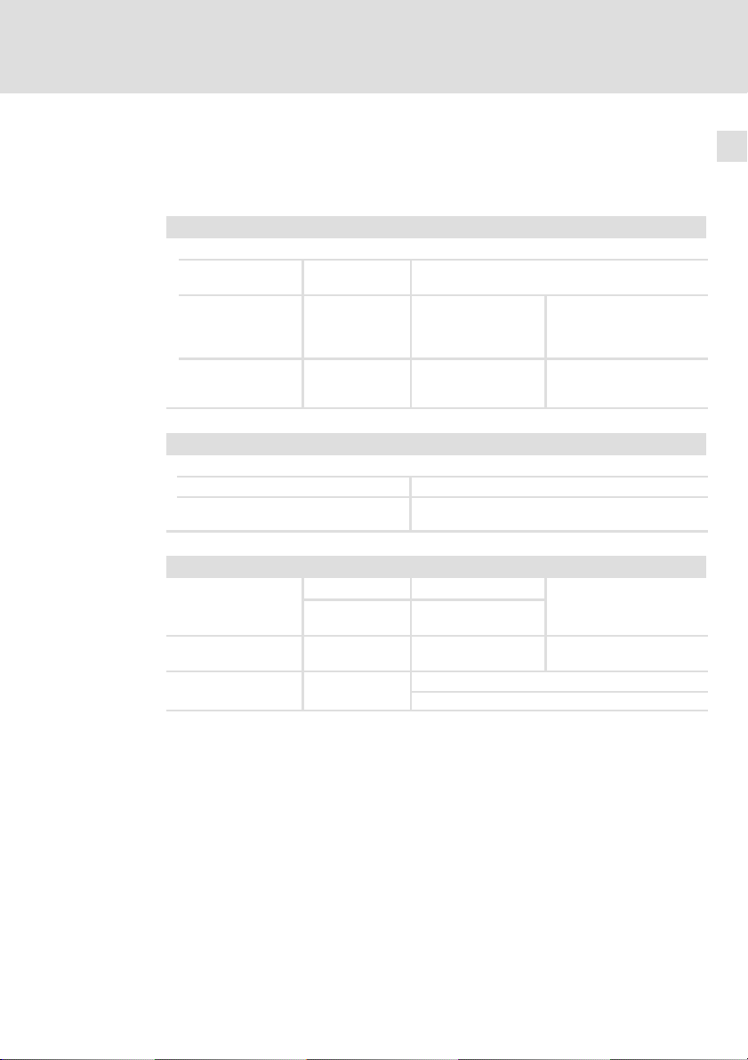
4.3 Mechanische Daten
Verwendung mit 9400
Abb. 4−1 Abmessungen [mm]
SSP94NF302
16
Masse
[kg]
E94AZMP0824 29.0
E94AZMP2004 51.5
EDK94AZMP45 DE/EN/FR/ES/IT 7.0
Page 17
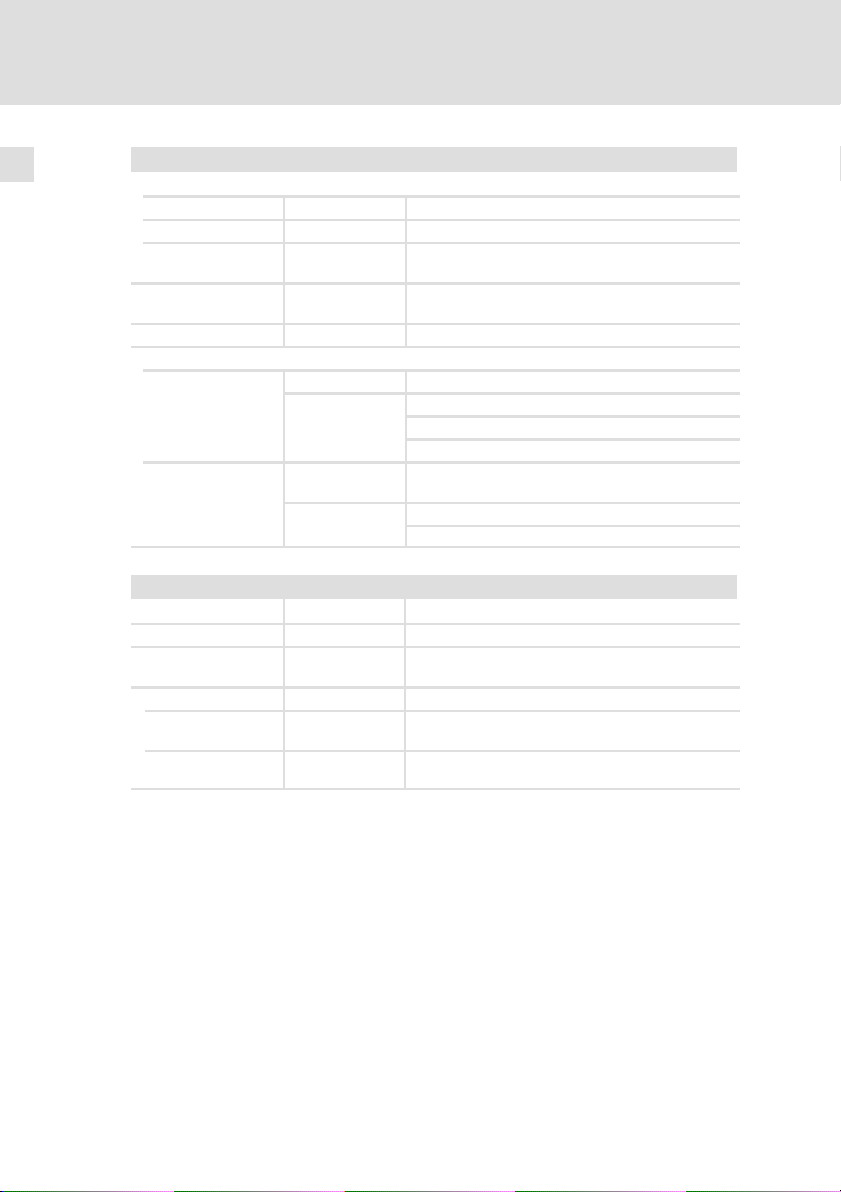
Verwendung mit i700
Technische Daten
Mechanische Daten
4
Abb. 4−2 Abmessungen [mm]
E94AZMP0824 29.0
E94AZMP2004 51.5
EDK94AZMP45 DE/EN/FR/ES/IT 7.0
SSP94NF302i7
Masse
[kg]
17
Page 18

5
Mechanische Installation
Wichtige Hinweise
5 Mechanische Installation
5.1 Wichtige Hinweise
ƒ Der Montageort muss den in den Technischen Daten genannten
Einsatzbedingungen immer entsprechen ( 13). Ggf. zusätzliche
Maßnahmen ergreifen.
ƒ Die Montageplatte des Schaltschranks muss folgende Eigenschaften
aufweisen:
– elektrisch leitfähig
– lackfrei
ƒ Die mechanischen Verbindungen müssen immer gewährleistet sein.
ƒ Eine ungehinderte Luftzirkulation zum Abführen der Wärme muss
gewährleistet sein.
18
EDK94AZMP45 DE/EN/FR/ES/IT 7.0
Page 19
5.2 Anordnung der Geräte
E94AZxPxxxx
Verwendung mit 9400
01
E94AZEX100
L1
L2
L3
+
...
E94AZPxxxxx
M
3~
...
Mechanische Installation
Anordnung der Geräte
+UG
-UG
E94AZPxxxxx
M
3~
+UG
-UG
+UG
-UG
5
Abb. 5−1 Anordnungsprinzip
EDK94AZMP45 DE/EN/FR/ES/IT 7.0
E94AZxPxxxx
E94APNExxxx
E94AZPxxxxx
(E94AZPPxxxx)
M
3~
Standard Montage: Nebenbau
Montagevariante: Überbau
E94AZxPxxxx Filter
E94APNExxxx DC Versorgungsmodul 9400
E94AZEX100 DC Einspeisestelle
E94AZPxxxxx Montagesockel Achsmodul 9400
(bis 36 A/18 kW mit Montagesockel E94AZPPxxxx)
E94AZPxxxxx
M
3~
SSP94FF003
19
Page 20
5
Mechanische Installation
Anordnung der Geräte
Verwendung mit i700
L1
L2
L3
...
E94AZxPxxxx
E70ACPSxxxx4x
Abb. 5−2 Anordnungsprinzip
Montage: Nebenbau
E94AZxPxxxx Filter (Netzanschluss: unten, Ausgang: oben)
E70ACPSxxxx4x DC Versorgungsmodul i700
E70AZEVE001 DC−Klemme i700 (nur bei verteilter Installation)
E70ACMS...
M
3~
...
E70ACMS...
M
3~
E70ACMS...
M
3~
E70ACMS...
M
3~
E70AZEVE001
+UG
-UG
SSP94FF003 S2
20
EDK94AZMP45 DE/EN/FR/ES/IT 7.0
Page 21
Mechanische Installation
Befestigungsraster
5
5.3 Befestigungsraster
Verwendung mit 9400
Wir empfehlen zur Befestigung der Geräte ein M5−Gewindelochraster in die
Montageplatte einzubringen. Durch diese Vorbereitung sind die Geräte einfach
zu befestigen. Die Gerätegrößen 1, 2, ... n sind so direkt anreihbar.
Abb. 5−3 Abmessungen [mm]
Lochraster für Montagesockel (Gerätegröße 1 bis 3)
Lochraster für andere Gerätegrößen oder Filter im Unterbau (nur Single Drive)
Kabelkanal
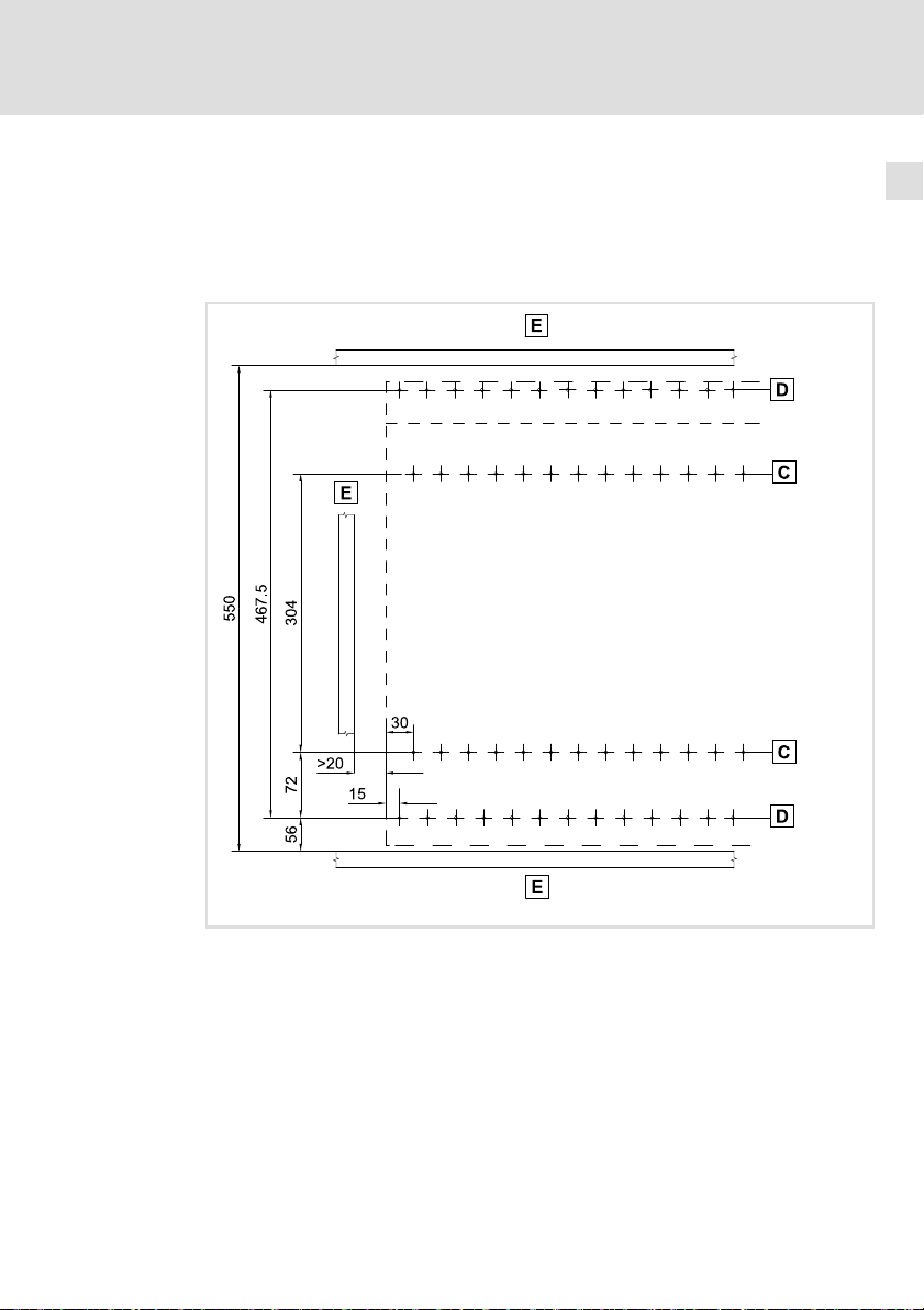
Verwendung mit i700
Bei Verwendung mit der Reihe i700 ist die Befestigung im Lochraster nicht möglich. Die Befestigungslöcher sind entsprechend der Maßzeichnung links neben
dem Versorgungsmodul E70ACPS... zu setzen.
EDK94AZMP45 DE/EN/FR/ES/IT 7.0
SSP94NF311
21
Page 22

5
Mechanische Installation
Montageschritte
5.4 Montageschritte
Stop!
Hohes Gerätegewicht
Das Gerät ist sehr schwer und muss für die Montage angehoben
werden.
Mögliche Folgen:
ƒ Personenschäden, insbesondere Rückenschäden beim Anheben
bzw. Halten des Gerätes
ƒ Sach− und Personenschäden durch Herunterfallen des Gerätes
Schutzmaßnahmen:
ƒ Gerät nur mit einer für das Gerätegewicht zugelassenen
Lastaufnahmeeinrichtung (z. B. Hallenkran) transportieren.
ƒ Hebezeug, Lastaufnahmeeinrichtung und Anschlagmittel vor
dem Transport auf ausreichende Tragfähigkeit und
einwandfreien Zustand prüfen.
ƒ Hebezeug und Anschlagmittel erst entfernen, wenn das Gerät
sicher auf einem tragfähigen Untergrund aufliegt oder endgültig
montiert ist.
22
EDK94AZMP45 DE/EN/FR/ES/IT 7.0
Page 23

Mechanische Installation
Montageschritte
Verwendung mit 9400
So gehen Sie bei der Montage vor:
1. Bereiten Sie auf der Montageplatte M5−Gewindebohrungen z. B. gemäß
dem Befestigungsraster vor.
– Nutzen Sie stets alle vorgegebenen Befestigungspunkte.
2. Schrauben Sie das Filter auf die Montageplatte.
– Verwenden Sie M5−Kombischrauben oder
M5−Innensechskantschrauben mit Unterlegscheibe.
– Wenn Sie rechts vom Filter weitere Geräte direkt anreihen möchten,
ziehen Sie die Schrauben erst fest an, nachdem alle Geräte montiert
und ausgerichtet sind.
– Anzugsmoment: 3.4 Nm (30 lb−in).
Verwendung mit i700
So gehen Sie bei der Montage vor:
1. Bereiten Sie auf der Montageplatte M5−Gewindebohrungen vor.
– Nutzen Sie stets alle vorgegebenen Befestigungspunkte.
2. Schrauben Sie das Filter auf die Montageplatte.
– Verwenden Sie M5−Kombischrauben oder
M5−Innensechskantschrauben mit Unterlegscheibe.
– Anzugsmoment: 3.4 Nm (30 lb−in).
5
EDK94AZMP45 DE/EN/FR/ES/IT 7.0
23
Page 24

6
Elektrische Installation
Wichtige Hinweise
6 Elektrische Installation
6.1 Wichtige Hinweise
ƒ Die Installation muss
– den in den Technischen Daten genannten Einsatzbedingungen immer
entsprechen ( 13).
– nach EN 60204−1 ausgeführt werden.
ƒ Bei der Auswahl des Leitungstyps beachten:
– Die verwendeten Leitungen müssen den geforderten Approbationen
am Einsatzort entsprechen (z. B. VDE, UL usw.).
– Absicherung und Leitungsquerschnitte gemäß den Vorgaben in der
Dokumentation zum Grundgerät bemessen.
Gefahr!
Gefährliche elektrische Spannung
Alle Leistungsanschlüsse führen bis zu 3 Minuten nach
Netz−Ausschalten gefährliche elektrische Spannung.
Mögliche Folgen:
ƒ Tod oder schwere Verletzungen beim Berühren der
Leistungsanschlüsse.
Schutzmaßnahmen:
ƒ Vor Arbeiten an den Leistungsanschlüssen Netz abschalten und
mindestens 3 Minuten warten.
ƒ Prüfen, ob alle Leistungsanschlüsse spannungsfrei sind.
24
EDK94AZMP45 DE/EN/FR/ES/IT 7.0
Page 25

Elektrische Installation
Wichtige Hinweise
Gefahr!
Gefährliche elektrische Spannung
Der Ableitstrom gegen Erde (PE) ist > 3.5 mA AC bzw. > 10 mA DC.
Mögliche Folgen:
ƒ Tod oder schwere Verletzungen beim Berühren des Gerätes im
Fehlerfall.
Schutzmaßnahmen:
Die in der EN 61800−5−1 geforderten Maßnahmen umsetzen.
Insbesondere:
ƒ Festinstallation
– PE−Anschluss normgerecht ausführen.
– PE−Leiter doppelt auflegen oder PE−Leiterquerschnitt ³ 10 mm
ƒ Anschluss mit einem Steckverbinder für industrielle
Anwendungen nach IEC 60309 (CEE):
– PE−Leiterquerschnitt ³ 2.5 mm2 als Teil eines mehradrigen
Versorgungskabels.
– Angemessene Zugentlastung vorsehen.
Stop!
Kein Geräteschutz gegen zu hohe Netzspannung
Der Netzeingang ist intern nicht abgesichert.
Mögliche Folgen:
ƒ Zerstörung des Gerätes bei zu hoher Netzspannung.
Schutzmaßnahmen:
ƒ Beachten Sie die maximal zulässige Netzspannung.
ƒ Sichern Sie das Gerät netzseitig fachgerecht gegen
Netzschwankungen und Spannungsspitzen ab.
6
2
.
EDK94AZMP45 DE/EN/FR/ES/IT 7.0
25
Page 26

6
Elektrische Installation
Wichtige Hinweise
Stop!
Filter kann überhitzen
Nach Ausfall einer Netzphase oder des Lüfters wird das Filter sehr
heiß.
Mögliche Folgen:
ƒ Das Filter überhitzt und wird zerstört.
Schutzmaßnahmen:
ƒ Den Thermokontakt des Filters immer anschließen und so in die
Anlagenüberwachung einbinden, dass bei Überhitzung des
Filters die Netzversorgung abgeschaltet wird (z. B. die
Netzschütz−Ansteuerung abschalten).
ƒ Das Filter nur mit funktionierendem Lüfter betreiben.
26
EDK94AZMP45 DE/EN/FR/ES/IT 7.0
Page 27
Elektrische Installation
Anschlussplan
6
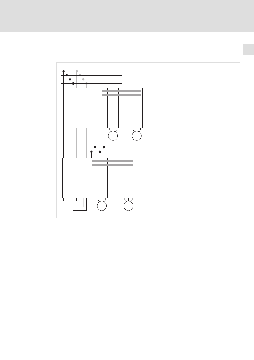
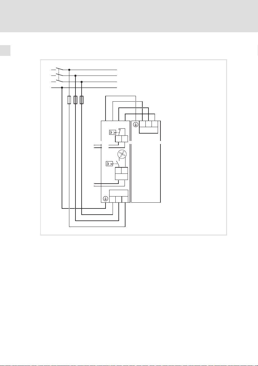
6.2 Anschlussplan
Verwendung mit 9400
Standardmontage Montagevariante
K1
L1
L2
L3
PE
L1 L1
+
E94AZRPxxxx
E94AZMPxxxx
X302
1 (BK)
F1...F3
L3 L3
L2 L2
T1 T2
24V
X11
2 (BK)
0V
3 (BK)
+
E94APNExxxx
X112
+
L1
L2
X301 X111
K1
L1
L2
L3
PE
F1...F3
L3
L1 L2
+
X301
T1
T2
E94AZRPxxxxE94AZMPxxxx
0V
24V
X11
L3
X302
1 (BK)
2 (BK)
3 (BK)
PE (GN/YE)
Abb. 6−1 Schaltungsprinzip
E94AZMPxxxx Netzfilter
E94APNExxxx DC Versorgungsmodul 9400
F1 ... F3 Sicherungen
K1 Netzschütz
EDK94AZMP45 DE/EN/FR/ES/IT 7.0
PE (GN/YE)
L3
L1 L2
+
X111
SSP94NF305 SSP94NF305
E94APNExxxx
27
Page 28
6
Elektrische Installation
Anschlussplan
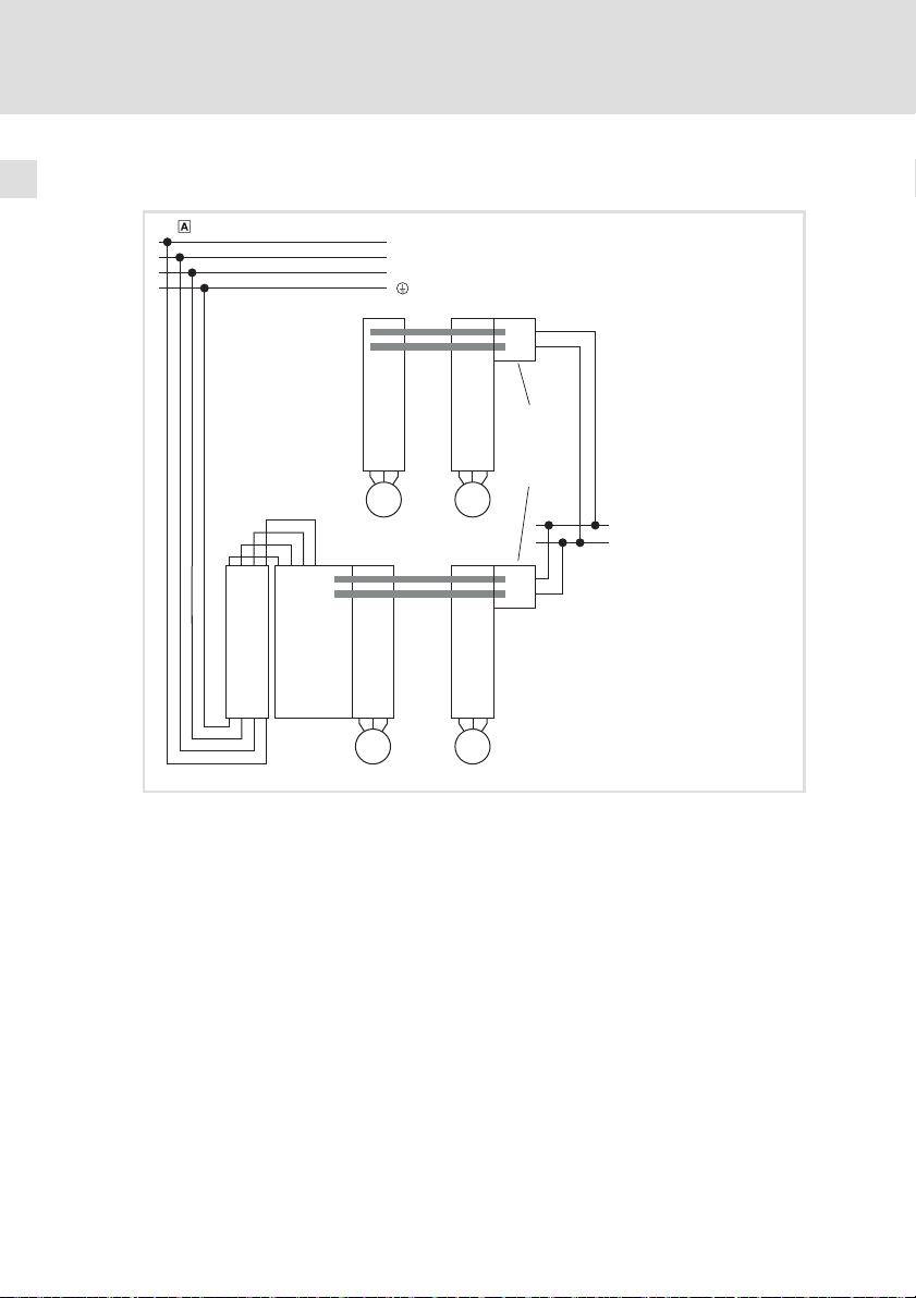
Verwendung mit i700
K1
L1
L2
L3
PE
F1...F3
Abb. 6−2 Schaltungsprinzip
E94AZRPxxxx Funk−Entstörfilter
E70ACPSxxxx4x DC Versorgungsmodul i700
F1 ... F3 Sicherungen
K1 Netzschütz
PE (GN/YE)
1 (BK)
X302
E94AZRPxxxx
E94AZMPxxxx
L3
2 (BK)
T1 T2
24V
X11
X301
3 (BK)
0V
L1L1L2
L2
X100
E70ACPSxxxx4x
L3
SSP94FF305 S2
28
EDK94AZMP45 DE/EN/FR/ES/IT 7.0
Page 29
Elektrische Installation
Anschlussdaten
6
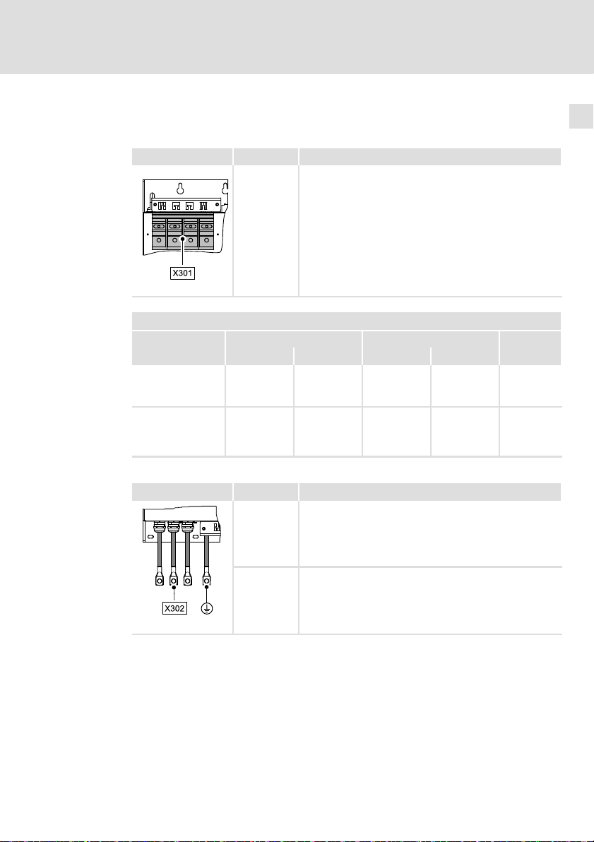
6.3 Anschlussdaten
Netz
Klemme X301 Beschriftung Beschreibung
SSP94NF306
Klemmendaten
E94AZxP0824
Anschluss mit
Ringkabelschuh M8
E94AZxP2004
Anschluss mit
Ringkabelschuh
M10
Versorgungsmodul
Leitung X302 Beschriftung Beschreibung
L1
L2
L3
PE
max. Leiterquerschnitt Anzugsmoment
[mm2] [AWG] [Nm] [lb−in]
70
(2 x 70)
150
(2 x 120)
L1’
L2’
L3’
Anschluss der Netzphasen L1, L2, L3 und des Schutzleiters
PE
2/0 12 106 SW13
250 mcm 20 177 SW15
Filter−Ausgangsleiter (Litze mit Ringkabelschuh, Farbe BK)
SSP94NF307
EDK94AZMP45 DE/EN/FR/ES/IT 7.0
Ausgangsseitiger Schutzleiter (Litze mit Ringkabelschuh,
Farbe GN/YE)
29
Page 30
6
Elektrische Installation
Anschlussdaten
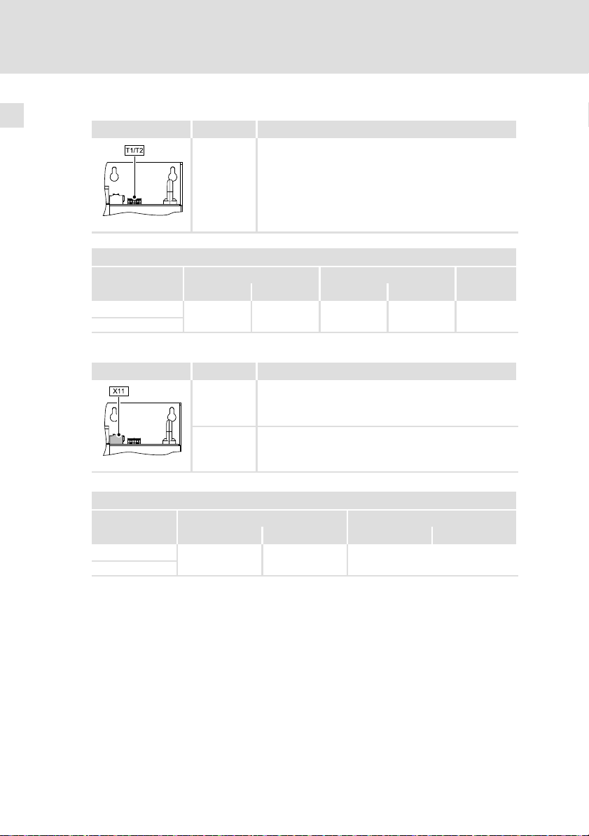
Thermokontakt
Klemme T1/T2 Beschriftung Beschreibung
SSP94NF308
Klemmendaten
E94AZxP0824
E94AZxP2004
T1
T2
max. Leiterquerschnitt Anzugsmoment
[mm2] [AWG] [Nm] [lb−in]
4.0
Anschluss Thermokontakt
10 0.6 ... 0.8 5.3 ... 7.1 PZ1
Lüfter
Klemme X11 Beschriftung Beschreibung
GE GND Externe Versorgung
30
SSP94NF309
Klemmendaten
E94AZMP0824
E94AZMP2004
24E 24 V Externe Versorgung durch ein sicher getrenntes Netz-
[mm2] [AWG] [Nm] [lb−in]
0.2 ... 2.5
teil (SELV/PELV)
Leiterquerschnitt Anzugsmoment
24 ... 12 −
EDK94AZMP45 DE/EN/FR/ES/IT 7.0
Page 31

Elektrische Installation
Montageschritte
6
6.4 Montageschritte
SSP94NF310
EDK94AZMP45 DE/EN/FR/ES/IT 7.0
31
Page 32

6
Elektrische Installation
Montageschritte
Verwendung mit 9400
So schließen Sie das Filter an:
1. Filter−Ausgangsleitungen (X302/L1’, L2’, L3’, PE’) am Versorgungsmodul
anschließen.
2. Deckel demontieren.
3. Netzleitungen mit Ringkabelschuhen auf die Gewindebolzen X301/L1, L2,
L3 schrauben.
– Anzugsmoment beachten! ( 29)
4. Netzseitiger Schutzleiter mit Ringkabelschuh auf den Gewindebolzen
X301/PE schrauben.
– Anzugsmoment beachten! ( 29)
– Der PE−Anschluss muss nach EN 61800−5−1 ausgeführt werden.
5. Alle netzseitigen Leitungen am Zugentlastungsblech mit Kabelbindern
fixieren.
6. Deckel montieren.
– Ohne Deckel darf das Filter nicht in Betrieb genommen werden!
7. Thermokontakt−Leitung am Anschluss T1 und T2 auflegen.
– Den Thermokontakt so in die Anlagenüberwachung einbinden, dass bei
Überhitzung des Filters die Netzversorgung abgeschaltet wird.
8. Spannungsversorgung des internen Lüfters am Anschluss X11 auflegen.
32
EDK94AZMP45 DE/EN/FR/ES/IT 7.0
Page 33

Elektrische Installation
Montageschritte
Verwendung mit i700
So schließen Sie das Filter an:
1. Filter−Ausgangsleitungen (X302/L1’, L2’, L3’, PE’) am Versorgungsmodul
anschließen.
– Leitungsenden (Kabelschuhe) dürfen entfernt werden.
– Leitungslängen dürfen bei Bedarf gekürzt werden.
– Beim Anschluss der Ausgangsleiter an die Netzklemme X100 der
Reihe i700 keine Aderendhülsen verwenden.
2. Deckel demontieren.
3. Netzleitungen mit Ringkabelschuhen auf die Gewindebolzen X301/L1, L2,
L3 schrauben.
– Anzugsmoment beachten! ( 29)
4. Netzseitiger Schutzleiter mit Ringkabelschuh auf den Gewindebolzen
X301/PE schrauben.
– Anzugsmoment beachten! ( 29)
– Der PE−Anschluss muss nach EN 61800−5−1 ausgeführt werden.
5. Alle netzseitigen Leitungen am Zugentlastungsblech mit Kabelbindern
fixieren.
6. Deckel montieren.
– Ohne Deckel darf das Filter nicht in Betrieb genommen werden!
6
EDK94AZMP45 DE/EN/FR/ES/IT 7.0
33
Page 34

6
Elektrische Installation
Montageschritte
34
EDK94AZMP45 DE/EN/FR/ES/IT 7.0
Page 35

Contents i
1 About this documentation 36. . . . . . . . . . . . . . . . . . . . . . . . . . . . . . . . . . . . . . . . . .
1.1 Validity information 36. . . . . . . . . . . . . . . . . . . . . . . . . . . . . . . . . . . . . . . .
1.2 Target group 36. . . . . . . . . . . . . . . . . . . . . . . . . . . . . . . . . . . . . . . . . . . . . .
1.3 Document history 36. . . . . . . . . . . . . . . . . . . . . . . . . . . . . . . . . . . . . . . . . .
1.4 Conventions used 37. . . . . . . . . . . . . . . . . . . . . . . . . . . . . . . . . . . . . . . . . . .
1.5 Notes used 37. . . . . . . . . . . . . . . . . . . . . . . . . . . . . . . . . . . . . . . . . . . . . . . .
2 Safety instructions 39. . . . . . . . . . . . . . . . . . . . . . . . . . . . . . . . . . . . . . . . . . . . . . . .
2.1 General safety information 39. . . . . . . . . . . . . . . . . . . . . . . . . . . . . . . . . . .
2.2 Residual hazards 40. . . . . . . . . . . . . . . . . . . . . . . . . . . . . . . . . . . . . . . . . . .
3 Product description 42. . . . . . . . . . . . . . . . . . . . . . . . . . . . . . . . . . . . . . . . . . . . . . .
3.1 Scope of supply 42. . . . . . . . . . . . . . . . . . . . . . . . . . . . . . . . . . . . . . . . . . . .
3.2 Overview 42. . . . . . . . . . . . . . . . . . . . . . . . . . . . . . . . . . . . . . . . . . . . . . . . . .
3.3 Identification 43. . . . . . . . . . . . . . . . . . . . . . . . . . . . . . . . . . . . . . . . . . . . . .
3.4 Operating conditions 43. . . . . . . . . . . . . . . . . . . . . . . . . . . . . . . . . . . . . . . .
4 Technical data 44. . . . . . . . . . . . . . . . . . . . . . . . . . . . . . . . . . . . . . . . . . . . . . . . . . . .
4.1 General data and operating conditions 44. . . . . . . . . . . . . . . . . . . . . . . .
4.2 Rated data 46. . . . . . . . . . . . . . . . . . . . . . . . . . . . . . . . . . . . . . . . . . . . . . . .
4.3 Mechanical data 47. . . . . . . . . . . . . . . . . . . . . . . . . . . . . . . . . . . . . . . . . .
5 Mechanical installation 49. . . . . . . . . . . . . . . . . . . . . . . . . . . . . . . . . . . . . . . . . . . .
5.1 Important notes 49. . . . . . . . . . . . . . . . . . . . . . . . . . . . . . . . . . . . . . . . . . . .
5.2 Arrangement of the devices 50. . . . . . . . . . . . . . . . . . . . . . . . . . . . . . . . . .
5.3 Mounting grid 52. . . . . . . . . . . . . . . . . . . . . . . . . . . . . . . . . . . . . . . . . . . . .
5.4 Mounting steps 53. . . . . . . . . . . . . . . . . . . . . . . . . . . . . . . . . . . . . . . . . . . .
6 Electrical installation 55. . . . . . . . . . . . . . . . . . . . . . . . . . . . . . . . . . . . . . . . . . . . . .
6.1 Important notes 55. . . . . . . . . . . . . . . . . . . . . . . . . . . . . . . . . . . . . . . . . . . .
6.2 Connection plan 58. . . . . . . . . . . . . . . . . . . . . . . . . . . . . . . . . . . . . . . . . . . .
6.3 Connection data 60. . . . . . . . . . . . . . . . . . . . . . . . . . . . . . . . . . . . . . . . . . . .
6.4 Mounting steps 62. . . . . . . . . . . . . . . . . . . . . . . . . . . . . . . . . . . . . . . . . . . .
EDK94AZMP45 DE/EN/FR/ES/IT 7.0
35
Page 36

1
About this documentation
Validity information
1 About this documentation
0Fig. 0Tab. 0
1.1 Validity information
These instructions are valid for
ƒ Mains filter E94AZMP0824
ƒ Mains filter E94AZMP2004
1.2 Target group
This documentation is directed at qualified skilled personnel according to
IEC 60364.
Qualified skilled personnel are persons who have the required qualifications to
carry out all activities involved in installing, mounting, commissioning, and
operating the product.
Tip!
Information and tools concerning the Lenze products can be found
in the download area under
www.lenze.com
1.3 Document history
Material number Version Description
.P>2 7.0 09/2014 TD29 UL notes in French for Canada
.M.: 6.0 10/2013 TD15 Supplements for i700
.BSñ 5.0 04/2010 TD29 Layout adaptation and revision
.=)| 4.0 01/2009 TD29 New edition due to reorganisation of the
.8gd 3.0 02/2008 TD29 Revision
.6@N 2.0 06/2007 TD29 Revision
.5b# 1.1 04/2007 TD29 First edition, in five languages
.5b# 1.0 04/2007 TD29 First edition, German
EAC Conformity
General corrections
company
36
EDK94AZMP45 DE/EN/FR/ES/IT 7.0
Page 37

1.4 Conventions used
Type of information Identification Examples/notes
Spelling of numbers
Decimal separator Point In general, the decimal point is used.
Text
Program name » « PC software
About this documentation
Conventions used
For instance: 1234.56
For example: »Engineer«, »Global
Drive Control« (GDC)
1
1.5 Notes used
The following pictographs and signal words are used in this documentation to
indicate dangers and important information:
Safety instructions
Structure of safety instructions:
Danger!
(characterises the type and severity of danger)
Note
(describes the danger and gives information about how to prevent
dangerous situations)
Pictograph and signal word Meaning
Danger!
Danger!
Stop!
Danger of personal injury through dangerous electrical
voltage.
Reference to an imminent danger that may result in
death or serious personal injury if the corresponding
measures are not taken.
Danger of personal injury through a general source of
danger.
Reference to an imminent danger that may result in
death or serious personal injury if the corresponding
measures are not taken.
Danger of property damage.
Reference to a possible danger that may result in
property damage if the corresponding measures are not
taken.
EDK94AZMP45 DE/EN/FR/ES/IT 7.0
37
Page 38

1
About this documentation
Notes used
Application notes
Pictograph and signal word Meaning
Note!
Tip!
Special safety instructions and application notes
Pictograph and signal word Meaning
Warnings!
Warnings!
Important note to ensure troublefree operation
Useful tip for simple handling
Reference to another documentation
Safety note or application note for the operation
according to UL or CSA requirements.
The measures are required to meet the requirements
according to UL or CSA.
38
EDK94AZMP45 DE/EN/FR/ES/IT 7.0
Page 39

2 Safety instructions
2.1 General safety information
Danger!
Disregarding the following basic safety measures may lead to
severe personal injury and damage to material assets!
ƒ Lenze drive and automation components ...
... must only be used for the intended purpose.
... must never be operated if damaged.
... must never be subjected to technical modifications.
... must never be operated unless completely assembled.
... must never be operated without the covers/guards.
... can − depending on their degree of protection − have live, movable or
rotating parts during or after operation. Surfaces can be hot.
ƒ All specifications of the corresponding enclosed documentation must be
observed.
This is vital for a safe and trouble−free operation and for achieving the
specified product features.
The procedural notes and circuit details provided in this document are
proposals which the user must check for suitability for his application. The
manufacturer does not accept any liability for the suitability of the specified
procedures and circuit proposals.
ƒ Only qualified skilled personnel are permitted to work with or on Lenze
drive and automation components.
According to IEC 60364 or CENELEC HD 384, these are persons ...
... who are familiar with the installation, assembly, commissioning and
operation of the product,
... possess the appropriate qualifications for their work,
... and are acquainted with and can apply all the accident prevent
regulations, directives and laws applicable at the place of use.
Safety instructions
General safety information
2
EDK94AZMP45 DE/EN/FR/ES/IT 7.0
39
Page 40

2
Safety instructions
Residual hazards
2.2 Residual hazards
Danger!
Dangerous electrical voltage
All power terminals remain live for up to three minutes after mains
disconnection.
Possible consequences:
ƒ Death or severe injuries when touching the power terminals.
Protective measures:
ƒ Switch off the power supply and wait for at least three minutes
before working on the power terminals.
ƒ Make sure that all power terminals are deenergised.
Warnings!
Conditions of Acceptability:
ƒ The products covered by this report are only intended for use
with Power Conversion Equipment (inverters).
ƒ Consideration shall be given to the field wiring leads. No strain
relief test was performed on the leads.
ƒ The devices in this report are only evaluated for factory wiring
use.
ƒ Temperature tests were performed with hook mounted drive.
40
EDK94AZMP45 DE/EN/FR/ES/IT 7.0
Page 41

Safety instructions
Residual hazards
Stop!
Heavy device weight
The device is very heavy and must be lifted for the mounting.
Possible consequences:
ƒ Injury to persons, particularly backache when lifting and holding
the device, respectively
ƒ Injury to persons and damage to material assets due to the
device falling down
Protective measures:
ƒ The device must only be carried with a load bearing system such
as an indoor crane permitted for the device weight
ƒ Before the transport, the hoist, the load bearing system and
lifting accessories must be checked for sufficient payload and
faultless status
ƒ Do not remove the hoist and the lifting accessories until the
device lies safe on a stable surface or is finally mounted.
2
EDK94AZMP45 DE/EN/FR/ES/IT 7.0
41
Page 42

3
Product description
Scope of supply
3 Product description
3.1 Scope of supply
Pos. Description
Mains filter E94AZMPxxxx
Mounting Instructions
3.2 Overview
42
Pos. Description
X301 Mains connection for L1 ... L3 and PE
X302 Connection cables to DC power supply module L1’ ... L3’ and PE
X11 Voltage supply for internal fan (24 V DC)
T1/T2 Thermal contact terminals T1, T2
Ring bolts
Nameplate
EDK94AZMP45 DE/EN/FR/ES/IT 7.0
SSP94NF301
Page 43

3.3 Identification
L
Type:
Type code E94 A Z M P xxx x
Product range
Version
Accessories
Type: mains filter
For 9400 power supply
Rated current [A]
Voltage class
4 = 230 ... 400/500 V
Product description
Identification
3
SSP94NF002
3.4 Operating conditions
The use of this filter is permissible with devices of the 9400 and i700 product
ranges starting from nameplate data:
E94APNE1004
E94APNE2454
E70ACPSx0604x Vx ˘
Assignment of filters to standard devices
Mains filter DC power supply module
Type Device size Type Device size
E94AZMP0824 4 E94APNE1004 4
E94AZMP2004 5 E94APNE2454 5
E94AZMP0824 4 E70ACPSx0604x 2
EDK94AZMP45 DE/EN/FR/ES/IT 7.0
HW SW
VA
˘
43
Page 44

4
Technical data
General data and operating conditions
4 Technical data
4.1 General data and operating conditions
Conformity and approval
Approval
UR
EAC TP TC 020/2011
EAC TP TC 004/2011
Mains data
Mains types
With grounded neutral (TT/TN systems)
Other mains types Observe instructions for special measures in the
Protection of persons and equipment
Enclosure
Earth leakage current IEC/EN 61800−5−1 > 3.5 mA AC
Insulation resistance IEC/EN 61800−5−1
UL508 Industrial Control Equipment, Underwriter
(TR CU 020/2011)
(TR CU 004/2011)
EN 60529
NEMA 250 Protection against
Laboratories (File−No. E219022) for USA and Canada
Electromagnetic
compatibility of
technical means
On safety of low
voltage equipment
Operation permitted without restrictions
documentation for the basic device!
IP20
contact to type 1
> 10 mA DC
< 2000 m site altitude: overvoltage category III
> 2000 m site altitude: overvoltage category II
Eurasian Conformity
TR CU: Technical Regulation
of Customs Union
Eurasian Conformity
TR CU: Technical Regulation
of Customs Union
Not in the wire range of the
terminals
Observe regulations and
safety instructions!
44
EDK94AZMP45 DE/EN/FR/ES/IT 7.0
Page 45

Technical data
General data and operating conditions
Environmental conditions
Climate
Storage
Transport IEC/EN 60721−3−2 2K3 (−25 ... +70 °C)
Operation IEC/EN 60721−3−3 3K3 (−10 ... +55 °C)
Site altitude 0 ... 4000 m amsl
Pollution EN 61800−5−1 Pollution degree 2
Vibration resistance (9.81 m/s
Transport
Operation
Mounting conditions
Mounting place In the control cabinet
Mounting position Vertically
Free space The required free space results from the mounting
Mounting position
Standard Side−by−side mounting; filter is directly screwed to
Variant Top mounting; the filter is screwed on top of the
IEC/EN 60721−3−1 1K3 (−25 ... +60 °C)
Current derating at +45 ... +55 °C: 2.5 %/°C
1000 ... 4000 m amsl: current derating of
5 %/1000 m
2
= 1 g)
IEC/EN 60721−3−2 2M2
EN 61800−2
Germanischer
Lloyd
IEC/EN 60068−2−6
2 ... 9 Hz: amplitude 3.5 mm
10 ... 200 Hz: acceleration resistant up to 10 m/s
200 ... 500 Hz: acceleration resistant up to 15 m/s
5 ... 13.2 Hz: amplitude ±1 mm
13.2 ... 100 Hz: acceleration resistant up to 0.7 g
10 ... 57 Hz: amplitude 0.075 mm
57 ... 150 Hz: acceleration resistant up to 1 g
position and the specifications of the standard
device.
the left of the standard device (Mechanical
installation)
basic device (Mechanical installation)
4
2
2
EDK94AZMP45 DE/EN/FR/ES/IT 7.0
45
Page 46

4
Technical data
Rated data
4.2 Rated data
Mains Voltage Voltage range Frequency range
3/PE AC 230 180 − 0 % ... 264 + 0 % 45 − 0 % ... 65 + 0 %
3/PE AC 400 320 − 0 % ... 440 + 0 % 45 − 0 % ... 65 + 0 %
3/PE AC 500 400 − 0 % ... 550 + 0 % 45 − 0 % ... 65 + 0 %
E94AZMP0824 230/400/500 50/60 82/82/82 61/61/61 3
E94AZMP2004 230/400/500 50/60 200/200/200 150/150/150 3
E94AZMP0824
Temperature in the control cabinet
2)
For i700 mounting: mains connection at the bottom, output at the top
E94AZMP0824 200 0.25 6.4
E94AZMP2004 350 0.10 6.3
Thermal contact
E94AZMP0824
E94AZMP2004
2)
U
[V] U
Lrated
Voltage Freq. Current [A] Current [A]
[V] [Hz] max. +45° C max. +55° C
400/500 50/60 49/49 30.6/30.6 3
Power loss Inductance Voltage drop
P
[W] L [mH] DU [V]
loss
Design max. switching voltage max. switching current
NC contact, 150 °C
[V] f [Hz]
Lrated
UTh [V AC] ITh [A]
250 2.5
Number
of phases
46
Fan
E94AZMP0824
E94AZMP2004
Voltage Current
[V DC] [A]
24
EDK94AZMP45 DE/EN/FR/ES/IT 7.0
0.3
Page 47

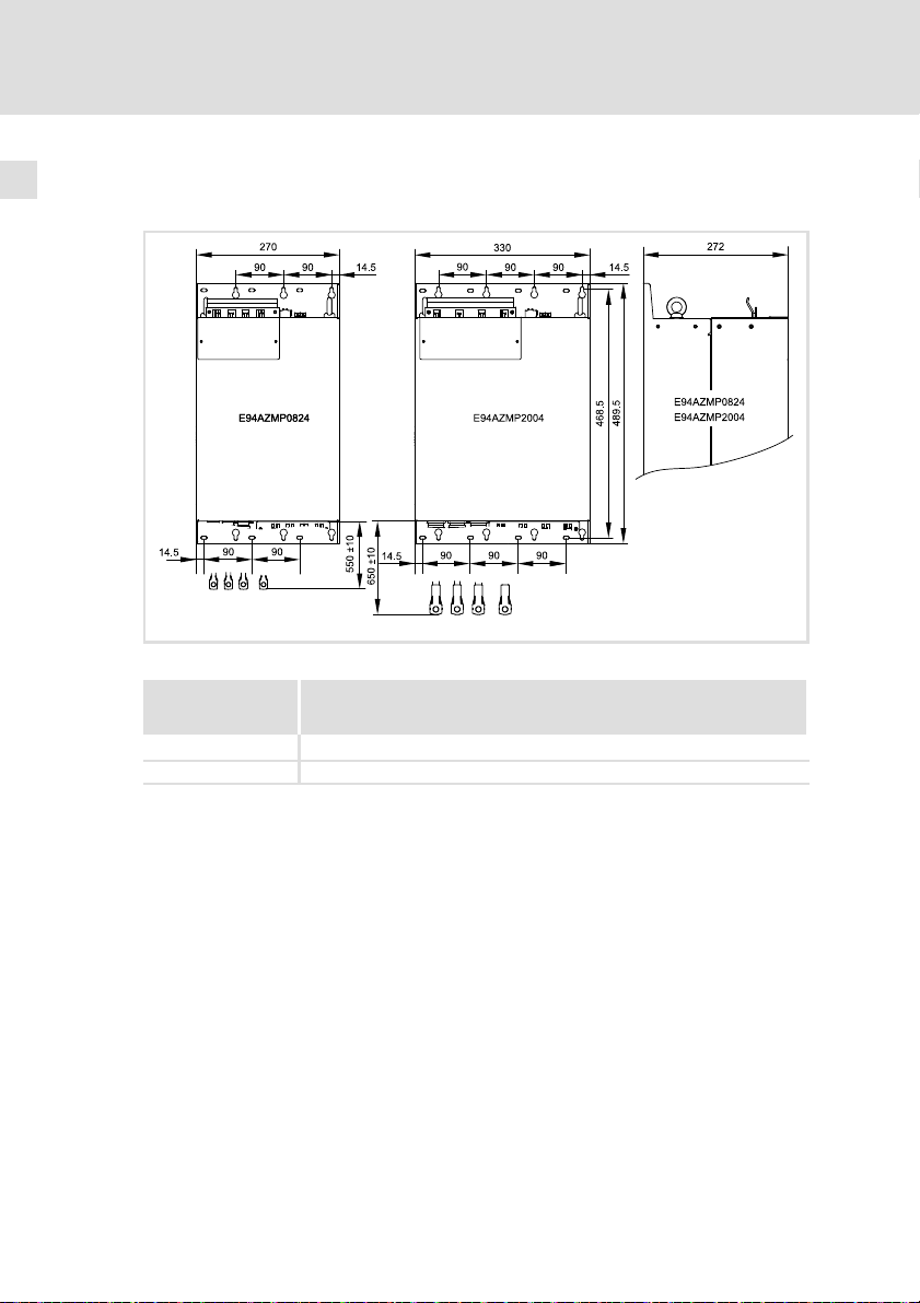
4.3 Mechanical data
Use with 9400
Fig. 4−1 Dimensions [mm]
Technical data
Mechanical data
4
SSP94NF302
E94AZMP0824 29.0
E94AZMP2004 51.5
EDK94AZMP45 DE/EN/FR/ES/IT 7.0
Mass
[kg]
47
Page 48

4
Technical data
Mechanical data
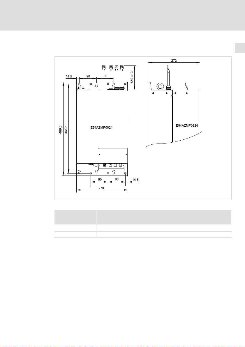
Use with i700
48
Fig. 4−2 Dimensions [mm]
Mass
E94AZMP0824 29.0
E94AZMP2004 51.5
SSP94NF302i7
[kg]
EDK94AZMP45 DE/EN/FR/ES/IT 7.0
Page 49

5 Mechanical installation
5.1 Important notes
ƒ The mounting location must always comply with the operating conditions
specified in the technical data ( 44). Take additional measures if
necessary.
ƒ The mounting plate of the control cabinet must have the following
properties:
– electrically conductive
– free of lacquer
ƒ The mechanical connections must always be ensured.
ƒ A free air circulation must be ensured for dissipating the heat.
Mechanical installation
Important notes
5
EDK94AZMP45 DE/EN/FR/ES/IT 7.0
49
Page 50

5
E94AZxPxxxx
Mechanical installation
Arrangement of the devices
5.2 Arrangement of the devices
Use with 9400
01
...
L1
L2
L3
+
+UG
-UG
E94AZxPxxxx
Fig. 5−1 Arrangement concept
Standard mounting: side mounting
Mounting variant: top mounting
E94AZxPxxxx Filter
E94APNExxxx 9400 DC power supply module
E94AZEX100 DC input module
E94AZPxxxxx Installation backplane for 9400 axis module
E94AZxPxxxx
E94APNExxxx
E94AZEX100
E94AZPxxxxx
(E94AZPPxxxx)
M
3~
E94AZPxxxxx
M
3~
E94AZPxxxxx
M
3~
+UG
-UG
+UG
-UG
...
E94AZPxxxxx
M
3~
(up to 36 A/18 kW with E94AZPPxxxx installation backplane)
SSP94FF003
50
EDK94AZMP45 DE/EN/FR/ES/IT 7.0
Page 51

Use with i700
Mechanical installation
Arrangement of the devices
L1
L2
L3
...
5
E94AZxPxxxx
E70ACPSxxxx4x
Fig. 5−2 Arrangement concept
Mounting: side mounting
E94AZxPxxxx Filter (mains connection: at the bottom, output: at the top)
E70ACPSxxxx4x i700 DC power supply module
E70AZEVE001 i700 DC terminal (only in the case of a distributed installation)
E70ACMS...
M
3~
...
E70ACMS...
M
3~
E70ACMS...
M
3~
E70ACMS...
M
3~
E70AZEVE001
+UG
-UG
SSP94FF003 S2
EDK94AZMP45 DE/EN/FR/ES/IT 7.0
51
Page 52

5
Mechanical installation
Mounting grid
5.3 Mounting grid
Use with 9400
We recommend to provide the mounting plate with a grid pattern of M5
threaded holes for attaching the devices. This preparation enables easy
attachment of the devices, and the device sizes 1, 2, ... n can thus be mounted
directly adjacent to each other.
52
SSP94NF311
Fig. 5−3 Dimensions [mm]
Hole pattern for installation backplane (device sizes 1 to 3)
Hole pattern for other device sizes or filters mounted below (only Single Drive)
Cable duct
Use with i700
For use in connection with the i700 series, fixing in the grid hole pattern is not
possible. The fixing holes are to be placed on the left next to the E70ACPS...
power supply module according to the dimensioned drawing.
EDK94AZMP45 DE/EN/FR/ES/IT 7.0
Page 53

Mechanical installation
Mounting steps
5
5.4 Mounting steps
Stop!
Heavy device weight
The device is very heavy and must be lifted for the mounting.
Possible consequences:
ƒ Injury to persons, particularly backache when lifting and holding
the device, respectively
ƒ Injury to persons and damage to material assets due to the
device falling down
Protective measures:
ƒ The device must only be carried with a load bearing system such
as an indoor crane permitted for the device weight
ƒ Before the transport, the hoist, the load bearing system and
lifting accessories must be checked for sufficient payload and
faultless status
ƒ Do not remove the hoist and the lifting accessories until the
device lies safe on a stable surface or is finally mounted.
EDK94AZMP45 DE/EN/FR/ES/IT 7.0
53
Page 54

5
Mechanical installation
Mounting steps
Use with 9400
Proceed as follows for the installation:
1. Prepare M5 threaded holes on the mounting plate, for instance according
to the mounting grid.
– Always use all mounting points specified.
2. Screw the filter onto the mounting plate.
– Use M5 screw and washer assemblies or M5 hexagon socket screws
with washers.
– If further devices are to be mounted directly adjacent on the right−hand
side of the filter, do not tighten the screws fully before all devices are
mounted and aligned.
– Tightening torque: 3.4 Nm (30 lb−in).
Use with i700
How to proceed during mounting:
1. Prepare M5 threaded holes on the mounting plate.
– Always use all fixing points specified.
2. Screw the filter to the mounting plate.
– Use M5 screw and washer assemblies or M5 hexagon socket screws
with washers.
– Tightening torque: 3.4 Nm (30 lb−in).
54
EDK94AZMP45 DE/EN/FR/ES/IT 7.0
Page 55

6 Electrical installation
6.1 Important notes
ƒ Installation must
– always be in accordance with the operating conditions specified in the
Technical data ( 44).
– be carried out to EN 60204−1.
ƒ Please observe the following when selecting the cable type:
– The cables used must comply with the approvals required for the
application (e. g. VDE, UL etc.).
– Fuses and cable cross−sections must be dimensioned in accordance with
the specifications in the documentation for the basic device.
Danger!
Dangerous electrical voltage
All power terminals remain live for up to three minutes after mains
disconnection.
Possible consequences:
ƒ Death or severe injuries when touching the power terminals.
Protective measures:
ƒ Switch off the power supply and wait for at least three minutes
before working on the power terminals.
ƒ Make sure that all power terminals are deenergised.
Electrical installation
Important notes
6
EDK94AZMP45 DE/EN/FR/ES/IT 7.0
55
Page 56

6
Electrical installation
Important notes
Danger!
Hazardous electrical voltage
The leakage current to earth (PE) is > 3.5 mA AC or > 10 mA DC.
Possible consequences:
ƒ Death or severe injuries when touching the device in the event of
an error.
Protective measures:
Implement the measures required in EN 61800−5−1. Especially:
ƒ Fixed installation
– Implement PE connection in compliance with standards.
– Connect PE conductor twice or PE conductor cross−section
³ 10 mm
ƒ Connection with a connector for industrial applications according
to IEC 60309 (CEE):
– PE conductor cross−section ³ 2.5 mm2 as part of a multi−core
supply cable.
– Provide for suitable strain relief.
2
.
Stop!
No device protection if the mains voltage is too high
The mains input is not internally fused.
Possible consequences:
ƒ Destruction of the device if the mains voltage is too high.
Protective measures:
ƒ Observe the maximally permissible mains voltage.
ƒ Fuse the device correctly on the supply side against mains
fluctuations and voltage peaks.
56
EDK94AZMP45 DE/EN/FR/ES/IT 7.0
Page 57

Electrical installation
Important notes
Stop!
Filter may overheat
After a mains phase or fan failure, the filter gets extremely hot.
Possible consequences:
ƒ The filter might overheat and be destroyed.
Protective measures:
ƒ Always connect the thermal contact of the filter and integrate it
such into the system monitoring that the mains supply will be
switched off (e.g. switch off the mains contactor control) when
the filter is overheated.
ƒ Only use the filter when the fan is working.
6
EDK94AZMP45 DE/EN/FR/ES/IT 7.0
57
Page 58

6
Electrical installation
Connection plan
6.2 Connection plan
Use with 9400
Standard mounting Mounting variant
K1
L1
L2
L3
PE
L1 L1
L2 L2
+
X301 X111
T1 T2
E94AZRPxxxx
E94AZMPxxxx
24V
X11
X302
1 (BK)
2 (BK)
F1...F3
L3 L3
+
E94APNExxxx
0V
X112
+
L1
L2
3 (BK)
K1
L1
L2
L3
PE
F1...F3
L3
L1 L2
+
X301
T1
T2
E94AZRPxxxxE94AZMPxxxx
0V
24V
X11
L3
X302
1 (BK)
2 (BK)
3 (BK)
58
PE (GN/YE)
Fig. 6−1 Connection concept
E94AZMPxxxx Mains filter
E94APNExxxx 9400 DC power supply module
F1 ... F3 Fuses
K1 Mains contactor
PE (GN/YE)
L3
L1 L2
+
X111
SSP94NF305 SSP94NF305
E94APNExxxx
EDK94AZMP45 DE/EN/FR/ES/IT 7.0
Page 59

Use with i700
K1
L1
L2
L3
PE
F1...F3
Electrical installation
Connection plan
6
Fig. 6−2 Connection concept
E94AZRPxxxx RFI filter
E70ACPSxxxx4x i700 DC power supply module
F1 ... F3 Fuses
K1 Mains contactor
PE (GN/YE)
X302
E94AZRPxxxx
E94AZMPxxxx
L3
1 (BK)
X301
2 (BK)
T1 T2
24V
X11
3 (BK)
0V
L1L1L2
L2
X100
E70ACPSxxxx4x
L3
SSP94FF305 S2
EDK94AZMP45 DE/EN/FR/ES/IT 7.0
59
Page 60

6
Electrical installation
Connection data
6.3 Connection data
Mains
Terminal X301 Labelling Description
SSP94NF306
Terminal data
E94AZxP0824
Connection with
M8 ring cable lug
E94AZxP2004
Connection with
M10 ring cable lug
Power supply module
Cable X302 Labelling Description
L1
L2
L3
PE
Max. conductor cross−section Tightening torque
[mm2] [AWG] [Nm] [lb−in]
70
(2 x 70)
150
(2 x 120)
L1’
L2’
L3’
Connection of mains phases L1, L2, L3 and PE conductor
2/0 12 106 SW13
250 mcm 20 177 SW15
Filter output conductor (lead with ring cable lug, colour BK)
60
SSP94NF307
Output PE conductor (lead with ring cable lug, colour
GN/YE)
EDK94AZMP45 DE/EN/FR/ES/IT 7.0
Page 61

Thermal contact
Terminal T1/T2 Labelling Description
Terminal data
E94AZxP0824
E94AZxP2004
T1
T2
SSP94NF308
Max. conductor cross−section Tightening torque
[mm2] [AWG] [Nm] [lb−in]
4.0
Connection of thermal contact
10 0.6 ... 0.8 5.3 ... 7.1 PZ1
Fan
Terminal X11 Labelling Description
GE GND External supply
Electrical installation
Connection data
6
SSP94NF309
Terminal data
E94AZMP0824
E94AZMP2004
EDK94AZMP45 DE/EN/FR/ES/IT 7.0
24E 24 V External supply through safely separated power
Conductor cross−section Tightening torque
[mm2] [AWG] [Nm] [lb−in]
0.2 ... 2.5
supply unit (SELV/PELV)
24 ... 12 −
61
Page 62

6
Electrical installation
Mounting steps
6.4 Mounting steps
SSP94NF310
62
EDK94AZMP45 DE/EN/FR/ES/IT 7.0
Page 63

Electrical installation
Mounting steps
Use with 9400
How to connect the filter:
1. Connect filter output cables (X302/L1’, L2’, L3’, PE’) to power supply
module.
2. Remove cover .
3. Use ring cable lugs to bolt mains cables onto threaded bolts X301/L1, L2,
L3.
– Observe tightening torque! ( 60)
4. Use ring cable lug to bolt mains−side PE conductor onto threaded bolt
X301/PE.
– Observe tightening torque! ( 60)
– PE connection must comply with EN 61800−5−1 .
5. Use cable binders to fix all mains−side cables at strain relief sheet .
6. Assemble cover .
– The filter must not be commissioned without cover !
7. Connect the thermal contact cable to T1 and T2 terminals.
– Integrate the thermal contact into the system monitoring in order that
the mains supply will be switched off in case of filter overheating.
8. Connect voltage supply for internal fan to terminal X11.
6
Use with i700
How to connect the filter:
1. Connect filter output cables (X302/L1’, L2’, L3’, PE’) to power supply
module.
– Cable ends (cable lugs) may be removed.
– Cable lengths may be shortened, if required.
– Do not use wire end ferrules for connecting filter output cables to the
i700 supply terminal.
2. Remove cover .
3. Use ring cable lugs to bolt mains cables onto threaded bolts X301/L1, L2,
L3.
– Observe tightening torque! ( 60)
4. Use ring cable lug to bolt mains side PE conductor onto threaded bolt
X301/PE.
– Observe tightening torque! ( 60)
– PE connection must comply with EN 61800−5−1.
5. Use cabke binders to fix all mains side cables on strain relief sheet .
6. Assemble cover .
– The filter must not be commissioned without cover !
EDK94AZMP45 DE/EN/FR/ES/IT 7.0
63
Page 64

6
Electrical installation
Mounting steps
64
EDK94AZMP45 DE/EN/FR/ES/IT 7.0
Page 65

Sommaire i
1 Présentation du document 66. . . . . . . . . . . . . . . . . . . . . . . . . . . . . . . . . . . . . . . . .
1.1 Validité 66. . . . . . . . . . . . . . . . . . . . . . . . . . . . . . . . . . . . . . . . . . . . . . . . . . .
1.2 Public visé 66. . . . . . . . . . . . . . . . . . . . . . . . . . . . . . . . . . . . . . . . . . . . . . . . .
1.3 Historique du document 66. . . . . . . . . . . . . . . . . . . . . . . . . . . . . . . . . . . . .
1.4 Conventions utilisées 67. . . . . . . . . . . . . . . . . . . . . . . . . . . . . . . . . . . . . . .
1.5 Consignes utilisées 67. . . . . . . . . . . . . . . . . . . . . . . . . . . . . . . . . . . . . . . . .
2 Consignes de sécurité 69. . . . . . . . . . . . . . . . . . . . . . . . . . . . . . . . . . . . . . . . . . . . . .
2.1 Consignes générales de sécurité 69. . . . . . . . . . . . . . . . . . . . . . . . . . . . . . .
2.2 Dangers résiduels 70. . . . . . . . . . . . . . . . . . . . . . . . . . . . . . . . . . . . . . . . . .
3 Description du produit 72. . . . . . . . . . . . . . . . . . . . . . . . . . . . . . . . . . . . . . . . . . . . .
3.1 Équipement livré> 72. . . . . . . . . . . . . . . . . . . . . . . . . . . . . . . . . . . . . . . . . .
3.2 Présentation générale 72. . . . . . . . . . . . . . . . . . . . . . . . . . . . . . . . . . . . . . .
3.3 Identification 73. . . . . . . . . . . . . . . . . . . . . . . . . . . . . . . . . . . . . . . . . . . . . .
3.4 Conditions d’utilisation 73. . . . . . . . . . . . . . . . . . . . . . . . . . . . . . . . . . . . . .
4 Spécifications techniques 74. . . . . . . . . . . . . . . . . . . . . . . . . . . . . . . . . . . . . . . . . .
4.1 Caractéristiques générales et conditions d’utilisation 74. . . . . . . . . . . .
4.2 Caractéristiques assignées 76. . . . . . . . . . . . . . . . . . . . . . . . . . . . . . . . . . .
4.3 Caractéristiques mécaniques 77. . . . . . . . . . . . . . . . . . . . . . . . . . . . . . . .
5 Installation mécanique 79. . . . . . . . . . . . . . . . . . . . . . . . . . . . . . . . . . . . . . . . . . . .
5.1 Remarques importantes 79. . . . . . . . . . . . . . . . . . . . . . . . . . . . . . . . . . . . .
5.2 Disposition des appareils 80. . . . . . . . . . . . . . . . . . . . . . . . . . . . . . . . . . . .
5.3 Grille de fixation 82. . . . . . . . . . . . . . . . . . . . . . . . . . . . . . . . . . . . . . . . . . .
5.4 Opérations de montage 83. . . . . . . . . . . . . . . . . . . . . . . . . . . . . . . . . . . . . .
6 Installation électrique 85. . . . . . . . . . . . . . . . . . . . . . . . . . . . . . . . . . . . . . . . . . . . .
6.1 Remarques importantes 85. . . . . . . . . . . . . . . . . . . . . . . . . . . . . . . . . . . . .
6.2 Schéma de câblage 88. . . . . . . . . . . . . . . . . . . . . . . . . . . . . . . . . . . . . . . . .
6.3 Données de raccordement 90. . . . . . . . . . . . . . . . . . . . . . . . . . . . . . . . . . .
6.4 Opérations de montage 92. . . . . . . . . . . . . . . . . . . . . . . . . . . . . . . . . . . . . .
EDK94AZMP45 DE/EN/FR/ES/IT 7.0
65
Page 66

1
Présentation du document
Validité
1 Présentation du document
0Fig. 0Tab. 0
1.1 Validité
Le présent document s’applique au produits suivants :
ƒ Filtre réseau E94AZMP0824
ƒ Filtre réseau E94AZMP2004
1.2 Public visé
Cette documentation s’adresse à un personnel qualifié et habilité
conformément à la norme CEI 60364.
On entend par "personnel qualifié et habilité" des personnes compétentes en
matière d’installation, de montage, de mise en service et de fonctionnement du
produit et possédant les qualifications correspondant à leurs activités.
Conseil !
Toutes les informations relatives aux produits Lenze peuvent être
téléchargées sur notre site à l’adresse suivante :
www.Lenze.com
1.3 Historique du document
Numéro de document Version Description
.P>2 7.0 09/2014 TD29 Consignes UL en français pour le Canada
.M.: 6.0 10/2013 TD15 Ajout des appareils i700
.BSñ 5.0 04/2010 TD29 Adaptation de la mise en page et texte revu
.=)| 4.0 01/2009 TD29 Nouvelle édition suite à la réorganisation de
.8gd 3.0 02/2008 TD29 Édition revue
.6@N 2.0 06/2007 TD29 Édition revue
.5b# 1.1 04/2007 TD29 Première édition, en 5 langues
.5b# 1.0 04/2007 TD29 Première édition, en allemand
Conformité EAC
Corrections générales
l’entreprise
66
EDK94AZMP45 DE/EN/FR/ES/IT 7.0
Page 67

1.4 Conventions utilisées
Type d’information Aperçu Exemples/remarques
Représentation des chiffres
Séparateur décimal Point Le point décimal est généralement
Mise en évidence de textes spéciaux
Nom de programme » « Logiciel pour PC
Présentation du document
Conventions utilisées
utilisé.
Exemple : 1234.56
Exemple : »Engineer«, »Global Drive
Control« (GDC)
1
1.5 Consignes utilisées
Pour indiquer des risques et des informations importantes, la présente
documentation utilise les mots et pictogrammes suivants :
Consignes de sécurité
Présentation des consignes de sécurité
Danger !
(Le pictogramme indique le type de risque.)
Explication
(L’explication décrit le risque et les moyens de l’éviter.)
Pictogramme et mot associé Explication
Danger !
Danger !
Stop !
Situation dangereuse pour les personnes en raison
d’une tension électrique élevée
Indication d’un danger imminent qui peut avoir pour
conséquences des blessures mortelles ou très graves en
cas de non−respect des consignes de sécurité
correspondantes
Situation dangereuse pour les personnes en raison d’un
danger d’ordre général
Indication d’un danger imminent qui peut avoir pour
conséquences des blessures mortelles ou très graves en
cas de non−respect des consignes de sécurité
correspondantes
Risques de dégâts matériels
Indication d’un risque potentiel qui peut avoir pour
conséquences des dégâts matériels en cas de
non−respect des consignes de sécurité correspondantes
EDK94AZMP45 DE/EN/FR/ES/IT 7.0
67
Page 68

1
Présentation du document
Consignes utilisées
Consignes d’utilisation
Pictogramme et mot associé Explication
Remarque
importante !
Conseil !
Consignes de sécurité et d’utilisation spéciales
Pictogramme et mot associé Description
Avertissements !
Avertissements !
Remarque importante pour assurer un fonctionnement
correct
Conseil utile pour faciliter la mise en uvre
Renvoi à une autre documentation
Consigne de sécurité ou d’utilisation pour le
fonctionnement selon les normes UL ou CSA.
Les mesures sont requises pour répondre aux exigences
des normes UL ou CSA.
68
EDK94AZMP45 DE/EN/FR/ES/IT 7.0
Page 69

2 Consignes de sécurité
2.1 Consignes générales de sécurité
Danger !
Le non−respect des consignes fondamentales de sécurité suivantes
peut entraîner des blessures et des dommages matériels graves.
ƒ Les composants d’entraînement et d’automatisation Lenze ...
... doivent exclusivement être utilisés conformément à leur fonction.
... ne doivent jamais être mis en service si des dommages sont décelés.
... ne doivent jamais être modifiés d’un point de vue technique.
... ne doivent jamais être mis en service s’ils ne sont pas montés
intégralement.
... ne doivent jamais être mis en service sans le capot obligatoire.
... peuvent − selon l’indice de protection − contenir des pièces sous tension, en
mouvement ou en rotation. Les surfaces peuvent être brûlantes.
ƒ Respecter les consignes et les indications contenues dans la
documentation concernée.
Il s’agit de la condition préalable pour garantir un fonctionnement sûr et
fiable et pour obtenir les caractéristiques du produit indiquées.
Les procédures à suivre et les plans de raccordement fournis constituent des
recommandations dont l’adéquation avec l’application concernée doit être
vérifiée. Lenze n’assumera aucune responsabilité pour les dommages liés à
un problème d’adéquation des procédures et plans de raccordements
indiqués.
ƒ Les travaux réalisés avec et au niveau des composants d’entraînement et
d’automatisation Lenze ne doivent être exécutés que par un personnel
qualifié et habilité.
Selon les normes CEI 60364 ou CENELEC HD 384, ces personnes doivent ...
... connaître parfaitement l’installation, le montage, la mise en service et le
fonctionnement du produit.
... posséder les qualifications appropriées pour l’exercice de leur activité.
... connaître toutes les prescriptions pour la prévention d’accidents,
directives et lois applicables sur le lieu d’utilisation et être en mesure de les
appliquer.
Consignes de sécurité
Consignes générales de sécurité
2
EDK94AZMP45 DE/EN/FR/ES/IT 7.0
69
Page 70

2
Consignes de sécurité
Dangers résiduels
2.2 Dangers résiduels
Danger !
Tension électrique dangereuse
Les raccordements de puissance sont encore sous tension jusqu’à 3
minutes après la coupure réseau.
Risques encourus :
ƒ Mort ou blessures graves en cas de contact accidentel avec les
raccordements de puissance.
Mesures de protection :
ƒ Avant toute intervention au niveau des raccordements de
puissance, couper l’alimentation et attendre au moins 3 minutes.
ƒ S’assurer que tous les raccordements de puissance sont hors
tension.
Avertissements !
Conditions d’acceptabilité :
ƒ Les produits concernés par ce rapport sont destinés
exclusivement à être utilisés avec des convertisseurs de
puissance (variateurs ou power conversion equipment).
ƒ Une attention particulière doit être apportée aux tresses de
câblage à pied d’oeuvre. Aucun test de décharge de traction n’a
été réalisé sur ces éléments.
ƒ Les équipements concernés par ce rapport sont évalués
exclusivement pour un câblage en usine.
ƒ Les tests de température ont été réalisés avec un entraînement à
crochet.
70
EDK94AZMP45 DE/EN/FR/ES/IT 7.0
Page 71

Consignes de sécurité
Dangers résiduels
Stop !
Appareil lourd
Cet appareil est très lourd et doit être soulevé pour le montage.
Risques encourus :
ƒ Blessures, notamment lombalgies causées par le fait de soulever
ou de maintenir l’appareil
ƒ Blessures et dommages matériels causés par une chute de
l’appareil
Mesures de protection :
ƒ Transporter l’appareil uniquement avec une installation de
suspension homologuée pour le poids de l’appareil (grue
d’entrepot par exemple).
ƒ Contrôler avant le transport la force de levage et l’état de
fonctionnement de l’appareil de levage, de l’installation de
suspension de charge et du dispositif de butée.
ƒ L’appareil de levage et le dispositif de butée ne doivent être
retirés que si l’appareil repose sur un support solide ou est
monté.
2
EDK94AZMP45 DE/EN/FR/ES/IT 7.0
71
Page 72

3
Description du produit
Équipement livré
3 Description du produit
3.1 Équipement livré>
Pos. Description
Filtre réseau E94AZMPxxxx
Instructions de montage
3.2 Présentation générale
72
Pos. Description
X301 Alimentation réseau L1 ... L3 et PE
X302 Câbles de raccordement au module d’alimentation CC L1’ ... L3’ et PE
X11 Alimentation du ventilateur intégré (24 V CC)
T1/T2 Borniers de raccordement T1, T2 du contact thermique
Oeillets de suspension
Plaque signalétique
EDK94AZMP45 DE/EN/FR/ES/IT 7.0
SSP94NF301
Page 73

3.3 Identification
L
Type:
Codification des types E94 A Z M P xxx x
Série d’appareils
Génération d’appareils
Accessoires
Type de filtre réseau
Pour 9400 Power Supply
Courant nominal [A]
Classe de tension
4 = 230 ... 400/500 V
Description du produit
Identification
3
SSP94NF002
3.4 Conditions d’utilisation
L’utilisation de ce filtre est autorisée pour les appareils séries 9400 et i700 à
partir de la version suivante (voir plaque signalétique) :
E94APNE1004
E94APNE2454
E70ACPSx0604x Vx ˘
Combinaisons entre les filtres et les appareils de base
Filtre réseau Module d’alimentation CC
Type Taille Type Taille
E94AZMP0824 4 E94APNE1004 4
E94AZMP2004 5 E94APNE2454 5
E94AZMP0824 4 E70ACPSx0604x 2
EDK94AZMP45 DE/EN/FR/ES/IT 7.0
HW SW
VA
˘
73
Page 74

4
Spécifications techniques
Caractéristiques générales et conditions d’utilisation
4 Spécifications techniques
4.1 Caractéristiques générales et conditions d’utilisation
Conformité et homologation
Homologation
UR
EAC TP TC 020/2011
EAC TP TC 004/2011
Informations sur les réseaux
Configurations réseau
Avec point Y à la terre (réseaux TT/TN)
Autres configurations réseau Respecter les indications concernant les mesures
UL508 Industrial Control Equipment, Underwriter
(RT UD 020/2011)
(RT UD 004/2011)
Laboratories (File−No. E219022) for USA and Canada
Compatibilité
électromagnétique des
équipements
Sécurité des
équipements à basse
tension
Utilisation sans restriction
particulières dans la documentation de l’appareil de
base !
Conformité eurasienne
RT UD : Règlement
technique de l’Union
Douanière
Conformité eurasienne
RT UD : Règlement
technique de l’Union
Douanière
74
Protection des personnes et protection de l’appareil
Indice de protection
Courant de fuite CEI/EN 61800−5−1 > 3.5 mA CA
Résistance d’isolement CEI/EN 61800−5−1
EN 60529
NEMA 250 Protection contre les
IP20
contacts accidentels
de type 1
> 10 mA CC
Altitude d’implantation < 2000 m : catégorie de
surtension III
Altitude d’implantation > 2000 m : catégorie de
surtension II
Pas dans la plage de
raccordement des bornes
Respecter les dispositions et
les consignes de sécurité !
EDK94AZMP45 DE/EN/FR/ES/IT 7.0
Page 75

Spécifications techniques
Caractéristiques générales et conditions d’utilisation
Conditions climatiques
Température ambiante
Stockage
Transport CEI/EN 60721−3−2 Classe 2K3 (−25 ... +70 °C)
Fonctionnement CEI/EN 60721−3−3 Classe 3K3 (−10 ... +55 °C)
Altitude
d’implantation
Pollution ambiante
admissible
Résistance aux chocs (9.81 m/s
Transport
Fonctionnement
CEI/EN 60721−3−1 Classe 1K3 (−25 ... +60 °C)
Réduction de courant entre +45 ... +55 °C : 2.5 %/°C
0 ... 4000 m au−dessus du niveau de la mer
1000 ... 4000 m au−dessus du niveau de la mer :
réduction de courant de 5 %/1000 m
EN 61800−5−1 Degré de pollution 2
2
= 1 g)
CEI/EN 60721−3−2 2M2
EN 61800−2
Germanischer
Lloyd
CEI/EN 60068−2−6
2 ... 9 Hz : amplitude de 3.5 mm
10 ... 200 Hz : résistance à l’accélération jusqu’à
2
10 m/s
200 ... 500 Hz : résistance à l’accélération jusqu’à
2
15 m/s
5 ... 13.2 Hz : amplitude de ±1 mm
13.2 ... 100 Hz : résistance à l’accélération jusqu’à
0.7 g
10 ... 57 Hz : amplitude de 0.075 mm
57 ... 150 Hz : résistance à l’accélération jusqu’à 1 g
4
Conditions de montage
Emplacement de
montage
Position de montage Verticale
Espaces de montage Les espaces de montage dépendent de la position de
Position de montage
Standard Montage latéral ; le filtre est vissé sans espace à
Variante Montage au−dessus ; le filtre est vissé au−dessus de
EDK94AZMP45 DE/EN/FR/ES/IT 7.0
En armoire électrique
montage et des données de l’appareil de base.
gauche de l’appareil de base ( Installation
mécanique).
l’appareil de base ( Installation mécanique).
75
Page 76

4
Spécifications techniques
Caractéristiques assignées
4.2 Caractéristiques assignées
Réseau Tension Plage de tension Plage de fréquence
U
LN
3/PE CA 230 180 − 0 % ... 264 + 0 % 45 − 0 % ... 65 + 0 %
3/PE CA 400 320 − 0 % ... 440 + 0 % 45 − 0 % ... 65 + 0 %
3/PE CA 500 400 − 0 % ... 550 + 0 % 45 − 0 % ... 65 + 0 %
Tension Fréq. Courant [A] Courant [A]
[V] [Hz] +45° C max. +55° C max.
E94AZMP0824 230/400/500 50/60 82/82/82 61/61/61 3
E94AZMP2004 230/400/500 50/60 200/200/200 150/150/150 3
E94AZMP0824
E94AZMP0824 200 0.25 6.4
E94AZMP2004 350 0.10 6.3
2)
Température dans l’armoire électrique
2)
Montage avec i700 : raccordement réseau vers le bas, sortie vers le haut
400/500 50/60 49/49 30.6/30.6 3
Puissance dissipée Inductance Chute de tension
Contact thermique
Version Tension de commutation
E94AZMP0824
E94AZMP2004
Contact à
ouverture, 150 °C
[V] U
PV [W] L [mH] DU [V]
[V] f [Hz]
LN
max.
UTh [V AC] ITh [A]
250 2.5
Courant de
commutation max.
Nombre
de
phases
76
Ventilateur
E94AZMP0824
E94AZMP2004
Tension Courant
[V CC] [A]
24
EDK94AZMP45 DE/EN/FR/ES/IT 7.0
0.3
Page 77

4.3 Caractéristiques mécaniques
Avec les appareils série 9400
Fig.4−1 Cotes [mm]
Spécifications techniques
Caractéristiques mécaniques
4
SSP94NF302
E94AZMP0824 29.0
E94AZMP2004 51.5
EDK94AZMP45 DE/EN/FR/ES/IT 7.0
Poids
[kg]
77
Page 78

4
Spécifications techniques
Caractéristiques mécaniques
Avec les appareils série i700
78
Fig.4−2 Cotes [mm]
Poids
E94AZMP0824 29.0
E94AZMP2004 51.5
SSP94NF302i7
[kg]
EDK94AZMP45 DE/EN/FR/ES/IT 7.0
Page 79

5 Installation mécanique
5.1 Remarques importantes
ƒ L’emplacement de montage doit impérativement remplir les conditions
d’utilisation décrites dans les spécifications techniques.( 74). Si
nécessaire, prendre des mesures complémentaires.
ƒ La plaque de montage de l’armoire électrique doit présenter les
caractéristiques suivantes :
– Conductivité électrique
– Pas de vernis
ƒ Les liaisons mécaniques doivent toujours être assurées.
ƒ Veiller à assurer une bonne circulation de l’air en vue de la dissipation de
la chaleur.
Installation mécanique
Remarques importantes
5
EDK94AZMP45 DE/EN/FR/ES/IT 7.0
79
Page 80

5
E94AZxPxxxx
Installation mécanique
Disposition des appareils
5.2 Disposition des appareils
Avec les appareils série 9400
01
...
L1
L2
L3
+
+UG
-UG
E94AZxPxxxx
E94AZxPxxxx
E94APNExxxx
(E94AZPPxxxx)
M
3~
Fig.5−1 Disposition des appareils (principe)
Montage standard : latéral
Variante de montage : au−dessus
E94AZxPxxxx Filtre
E94APNExxxx Module d’alimentation CC 9400
E94AZEX100 Module d’alimentation CC
E94AZPxxxxx Socle de montage : module d’axe 9400
E94AZPxxxxx
E94AZEX100
M
3~
E94AZPxxxxx
M
3~
+UG
-UG
+UG
-UG
...
E94AZPxxxxx
(jusqu’à 36 A/18 kW avec socle de montage E94AZPPxxxx)
E94AZPxxxxx
M
3~
SSP94FF003
80
EDK94AZMP45 DE/EN/FR/ES/IT 7.0
Page 81

Avec les appareils série i700
Installation mécanique
Disposition des appareils
L1
L2
L3
...
5
E70ACMS...
M
3~
...
E94AZxPxxxx
E70ACPSxxxx4x
Fig.5−2 Disposition des appareils (principe)
Montage : latéral
E94AZxPxxxx Filtre (raccordement réseau vers le bas, sortie vers le haut)
E70ACPSxxxx4x Module d’alimentation CC i700
E70AZEVE001 Bornier CC i700 (uniquement en cas d’installation répartie)
E70ACMS...
M
3~
E70ACMS...
M
3~
E70ACMS...
M
3~
E70AZEVE001
+UG
-UG
SSP94FF003 S2
EDK94AZMP45 DE/EN/FR/ES/IT 7.0
81
Page 82

5
Installation mécanique
Grille de fixation
5.3 Grille de fixation
Avec les appareils série 9400
Pour la fixation des appareils, nous recommandons le placement de la grille
perforée de trous taraudés M5 sur la plaque de montage. Le montage s’en
trouve simplifié. Les tailles d’appareil 1, 2, ... n peuvent ainsi être directement
juxtaposées.
82
SSP94NF311
Fig.5−3 Cotes [mm]
Grille perforée pour socle de montage (tailles d’appareil 1 à 3)
Grille perforée pour autres tailles d’appareil ou filtre en montage arrière
(variateurs mono−axes uniquement)
Cheminement de câble
Avec les appareils série i700
La fixation à l’aide de la grille perforée n’est pas possible pour les appareils série
i700. Dans ce cas de figure, prévoir des trous de fixation à gauche du module
d’alimentation E70ACPS... (voir schéma).
EDK94AZMP45 DE/EN/FR/ES/IT 7.0
Page 83

Installation mécanique
Opérations de montage
5
5.4 Opérations de montage
Stop !
Appareil lourd
Cet appareil est très lourd et doit être soulevé pour le montage.
Risques encourus :
ƒ Blessures, notamment lombalgies causées par le fait de soulever
ou de maintenir l’appareil
ƒ Blessures et dommages matériels causés par une chute de
l’appareil
Mesures de protection :
ƒ Transporter l’appareil uniquement avec une installation de
suspension homologuée pour le poids de l’appareil (grue
d’entrepot par exemple).
ƒ Contrôler avant le transport la force de levage et l’état de
fonctionnement de l’appareil de levage, de l’installation de
suspension de charge et du dispositif de butée.
ƒ L’appareil de levage et le dispositif de butée ne doivent être
retirés que si l’appareil repose sur un support solide ou est
monté.
EDK94AZMP45 DE/EN/FR/ES/IT 7.0
83
Page 84

5
Installation mécanique
Opérations de montage
Avec les appareils série 9400
Ordre des opérations de montage
1. Préparer les trous taraudés M5 sur la plaque de montage selon la grille de
fixation par exemple.
– Utiliser impérativement tous les points de fixation indiqués.
2. Visser le filtre sur la plaque de montage.
– Utiliser des vis cruciformes M5 ou des vis à six pans creux avec rondelle
incorporée.
– Si d’autres appareils doivent être juxtaposés du côté droit du filtre,
serrer les vis à fond uniquement après avoir monté et aligné tous les
appareils.
– Couple de serrage : 3.4 Nm (30 lb−in).
Avec les appareils série i700
Ordre des opérations de montage :
1. Préparer les trous taraudés M5 sur la plaque de montage.
– Utiliser impérativement tous les points de fixation indiqués.
2. Visser le filtre sur la plaque de montage.
– Utiliser des boulons avec rondelle incorporée M5 ou des vis à six pans
creux M5 avec rondelles.
– Couple de serrage : 3.4 Nm (30 lb−in).
84
EDK94AZMP45 DE/EN/FR/ES/IT 7.0
Page 85

6 Installation électrique
6.1 Remarques importantes
ƒ L’installation doit
– toujours respecter les conditions d’utilisation indiquées dans les
spécifications techniques ( 74) ;
– répondre aux exigences de la norme EN 60204−1.
ƒ Lors du choix du type de câble, tenir compte des points suivants :
– Les câbles utilisés doivent être conformes aux homologations requises
sur le lieu d’utilisation (exemples : VDE, UL, etc.).
– Les fusibles et les sections de câble doivent être dimensionnés
conformément aux prescriptions figurant dans la documentation de
l’appareil de base.
Danger !
Tension électrique dangereuse
Les raccordements de puissance sont encore sous tension jusqu’à 3
minutes après la coupure réseau.
Risques encourus :
ƒ Mort ou blessures graves en cas de contact accidentel avec les
raccordements de puissance.
Mesures de protection :
ƒ Avant toute intervention au niveau des raccordements de
puissance, couper l’alimentation et attendre au moins 3 minutes.
ƒ S’assurer que tous les raccordements de puissance sont hors
tension.
Installation électrique
Remarques importantes
6
EDK94AZMP45 DE/EN/FR/ES/IT 7.0
85
Page 86

6
Installation électrique
Remarques importantes
Danger !
Tension électrique dangereuse
Le courant de fuite vers la terre (PE) est > 3.5 mA CA ou > 10 mA CC.
Risques encourus :
ƒ Mort ou blessures graves en cas de contact accidentel avec
l’appareil en défaut
Mesures de protection :
Mettre en œuvre les mesures prescrites par la norme EN 61800−5−1,
notamment :
ƒ Installation fixe
– Prévoir un raccordement PE conformément à la norme.
– Prévoir un double raccordement du câble PE ou une section de
câble PE ³ 10 mm
ƒ Raccordement à l’aide d’un connecteur adapté aux applications
industrielles selon la norme CEI 60309 (CEE)
– La section de câble PE ³ 2.5 mm2 représente une partie du
câble d’alimentation multiconducteur.
– Utiliser un dispositif de décharge de traction adapté.
2
.
86
Stop !
Appareil non protégé contre une tension réseau trop élevée
Il n’y a pas de protection intégrée de l’entrée réseau.
Risques encourus :
ƒ Dommages irréversibles de l’appareil en cas de tension réseau
trop élevée
Mesures de protection :
ƒ Respecter la tension réseau maximale admissible.
ƒ Protéger l’appareil de manière adaptée côté réseau contre les
fluctuations du réseau et les pointes de tension.
EDK94AZMP45 DE/EN/FR/ES/IT 7.0
Page 87

Installation électrique
Remarques importantes
Stop !
Risque de surchauffe du filtre
Le filtre deviendra très chaud en cas de défaillance d’une phase
réseau ou du ventilateur.
Risques encourus :
ƒ Surchauffe ou destruction du filtre
Mesures de protection :
ƒ Veiller à ce que le contact thermique du filtre soit toujours en
circuit et intégré dans le système de surveillance de l’installation
de manière à ce que l’alimentation soit coupée en cas de
surchauffe du filtre (ex. : désactivation du contacteur réseau).
ƒ N’activer le filtre que lorsque le ventilateur est en marche.
6
EDK94AZMP45 DE/EN/FR/ES/IT 7.0
87
Page 88

6
Installation électrique
Schéma de câblage
6.2 Schéma de câblage
Avec les appareils série 9400
Montage standard Variante de montage
K1
L1
L2
L3
PE
L3 L3
L1 L1
L2 L2
+
X301 X111
T1 T2
E94AZRPxxxx
E94AZMPxxxx
0V
24V
X11
X302
1 (BK)
2 (BK)
3 (BK)
F1...F3
+
E94APNExxxx
+
L1
X112
L2
K1
L1
L2
L3
PE
F1...F3
L3
L1 L2
+
X301
T1
T2
E94AZRPxxxxE94AZMPxxxx
0V
24V
X11
L3
X302
1 (BK)
2 (BK)
3 (BK)
88
PE (GN/YE)
Fig.6−1 Principe de câblage
E94AZMPxxxx Filtre réseau
E94APNExxxx Module d’alimentation CC 9400
F1 ... F3 Fusibles
K1 Contacteur réseau
PE (GN/YE)
L3
L1 L2
+
X111
SSP94NF305 SSP94NF305
E94APNExxxx
EDK94AZMP45 DE/EN/FR/ES/IT 7.0
Page 89

Avec les appareils série i700
K1
L1
L2
L3
PE
F1...F3
Installation électrique
Schéma de câblage
6
Fig.6−2 Principe de câblage
E94AZRPxxxx Filtre antiparasite
E70ACPSxxxx4x Module d’alimentation CC i700
F1 ... F3 Fusibles
K1 Contacteur réseau
PE (GN/YE)
X302
E94AZRPxxxx
E94AZMPxxxx
L3
1 (BK)
X301
2 (BK)
T1 T2
24V
X11
3 (BK)
0V
L1L1L2
L2
X100
E70ACPSxxxx4x
L3
SSP94FF305 S2
EDK94AZMP45 DE/EN/FR/ES/IT 7.0
89
Page 90

6
Installation électrique
Données de raccordement
6.3 Données de raccordement
Réseau d’alimentation
Bornier X301 Marquage Description
L1
L2
L3
PE
SSP94NF306
Spécifications pour bornier
Section max. de câble Couple de serrage
[mm2] [AWG] [Nm] [lb−in]
E94AZxP0824
Raccordement avec
cosse à œillet M8
E94AZxP2004
Raccordement avec
cosse à œillet M10
70
(2 x 70)
150
(2 x 120)
Module d’alimentation
Câble X302 Marquage Description
L1’
L2’
L3’
Raccordement des phases réseau L1, L2, L3 et du
conducteur de protection PE
2/0 12 106 SW13
250 mcm 20 177 SW15
Fil de sortie du filtre (tresse avec cosse à œillet, couleur BK)
90
SSP94NF307
Conducteur de protection côté sortie (tresse avec cosse à
œillet, couleur GN/YE)
EDK94AZMP45 DE/EN/FR/ES/IT 7.0
Page 91

Contact thermique
Borne T1/T2 Marquage Description
T1
T2
SSP94NF308
Spécifications pour bornier
E94AZxP0824
E94AZxP2004
Section max. de câble Couple de serrage
[mm2] [AWG] [Nm] [lb−in]
4.0
Raccordement pour contact thermique
10 0.6 ... 0.8 5.3 ... 7.1 PZ1
Ventilateur
Borne X11 Marquage Description
GE Alimentation externe GND
Installation électrique
Données de raccordement
6
SSP94NF309
Spécifications pour bornier
E94AZMP0824
E94AZMP2004
EDK94AZMP45 DE/EN/FR/ES/IT 7.0
24E Alimentation externe 24 V via bloc d’alimentation avec
[mm2] [AWG] [Nm] [lb−in]
0.2 ... 2.5
coupure de sécurité (SELV/PELV)
Section de câble Couple de serrage
24 ... 12 −
91
Page 92

6
Installation électrique
Opérations de montage
6.4 Opérations de montage
SSP94NF310
92
EDK94AZMP45 DE/EN/FR/ES/IT 7.0
Page 93

Installation électrique
Opérations de montage
Avec les appareils série 9400
Ordre des opérations de raccordement du filtre
1. Relier les câbles de sortie du filtre (X302/L1’, L2’, L3’, PE’) au module
d’alimentation.
2. Ôter le couvercle de protection .
3. Visser les câbles réseau avec les cosses à oeillet sur les boulons filetés
X301/L1, L2, L3.
– Respecter le couple de serrage ! ( 90)
4. Visser le conducteur de protection côté réseau avec la cosse à oeillet sur le
boulon fileté X301/PE.
– Respecter le couple de serrage ! ( 90)
– Le raccordement PE doit être conforme aux prescriptions de la norme
EN 61800−5−1.
5. Fixer tous les câbles côté réseau sur la tôle de déchargement de traction
à l’aide de serre−câbles.
6. Remettre le couvercle de protection en place.
– En aucun cas, le filtre ne doit être mis en service sans le couvercle !
7. Raccorder le câble du contact thermique à T1 et T2.
– Intégrer le contact thermique dans le système de surveillance de
l’installation de façon à ce que l’alimentation réseau soit coupée en cas
de surchauffe du filtre.
8. Appliquer la tension d’alimentation du ventilateur intégré sur X11.
6
EDK94AZMP45 DE/EN/FR/ES/IT 7.0
93
Page 94

6
Installation électrique
Opérations de montage
Avec les appareils série i700
Ordre des opérations de raccordement du filtre :
1. Raccorder les câbles de sortie du filtre (X302/L1’, L2’, L3’, PE’) au module
d’alimentation.
– Les bouts (cosses) de câbles peuvent être enlevé(e)s.
– Les longueurs de câble peuvent être réduites si nécessaire.
– Ne pas utiliser des embouts si le câble de sortie est raccordé au bornier
réseau X100 des appareils série i700.
2. Ôter le couvercle de protection .
3. Visser les câbles réseau avec cosses à œillet sur les boulons filetés
X301/L1, L2, L3.
– Respecter le couple de serrage ! ( 90)
4. Visser le conducteur de protection côté réseau avec cosse à œillet sur le
boulon fileté X301/PE.
– Respecter le couple de serrage ! ( 90)
– Le raccordement à la terre doit être exécuté selon la norme
EN 61800−5−1.
5. Fixer tous les câbles côté réseau sur la tôle de support de charge à l’aide
de serre−câbles.
6. Monter le couvercle de protection .
– En aucun cas, le filtre ne doit être mis en service sans le couvercle !
94
EDK94AZMP45 DE/EN/FR/ES/IT 7.0
Page 95

Contenido i
1 Acerca de esta documentación 96. . . . . . . . . . . . . . . . . . . . . . . . . . . . . . . . . . . . . .
1.1 Información sobre la validez 96. . . . . . . . . . . . . . . . . . . . . . . . . . . . . . . . . .
1.2 Grupo objetivo 96. . . . . . . . . . . . . . . . . . . . . . . . . . . . . . . . . . . . . . . . . . . . .
1.3 Historia del documento 96. . . . . . . . . . . . . . . . . . . . . . . . . . . . . . . . . . . . . .
1.4 Convenciones utilizadas 97. . . . . . . . . . . . . . . . . . . . . . . . . . . . . . . . . . . . .
1.5 Indicaciones utilizadas 97. . . . . . . . . . . . . . . . . . . . . . . . . . . . . . . . . . . . . .
2 Instrucciones de seguridad 99. . . . . . . . . . . . . . . . . . . . . . . . . . . . . . . . . . . . . . . . .
2.1 Instrucciones generales de seguridad 99. . . . . . . . . . . . . . . . . . . . . . . . . .
2.2 Peligros residuales 100. . . . . . . . . . . . . . . . . . . . . . . . . . . . . . . . . . . . . . . . . .
3 Descripción del producto 102. . . . . . . . . . . . . . . . . . . . . . . . . . . . . . . . . . . . . . . . . .
3.1 Volumen de suministro 102. . . . . . . . . . . . . . . . . . . . . . . . . . . . . . . . . . . . . .
3.2 Vista general 102. . . . . . . . . . . . . . . . . . . . . . . . . . . . . . . . . . . . . . . . . . . . . . .
3.3 Identificación 103. . . . . . . . . . . . . . . . . . . . . . . . . . . . . . . . . . . . . . . . . . . . . .
3.4 Condiciones de uso 103. . . . . . . . . . . . . . . . . . . . . . . . . . . . . . . . . . . . . . . . .
4 Datos técnicos 104. . . . . . . . . . . . . . . . . . . . . . . . . . . . . . . . . . . . . . . . . . . . . . . . . . . .
4.1 Datos generales y condiciones de uso 104. . . . . . . . . . . . . . . . . . . . . . . . .
4.2 Datos nominales 106. . . . . . . . . . . . . . . . . . . . . . . . . . . . . . . . . . . . . . . . . . .
4.3 Datos mecánicos 107. . . . . . . . . . . . . . . . . . . . . . . . . . . . . . . . . . . . . . . . . .
5 Instalación mecánica 109. . . . . . . . . . . . . . . . . . . . . . . . . . . . . . . . . . . . . . . . . . . . . .
5.1 Indicaciones importantes 109. . . . . . . . . . . . . . . . . . . . . . . . . . . . . . . . . . . .
5.2 Colocación de los equipos 110. . . . . . . . . . . . . . . . . . . . . . . . . . . . . . . . . . . .
5.3 Plantilla de sujeción 112. . . . . . . . . . . . . . . . . . . . . . . . . . . . . . . . . . . . . . . . .
5.4 Pasos para el montaje 113. . . . . . . . . . . . . . . . . . . . . . . . . . . . . . . . . . . . . . .
6 Instalación eléctrica 115. . . . . . . . . . . . . . . . . . . . . . . . . . . . . . . . . . . . . . . . . . . . . . .
6.1 Indicaciones importantes 115. . . . . . . . . . . . . . . . . . . . . . . . . . . . . . . . . . . .
6.2 Esquema de conexiones 118. . . . . . . . . . . . . . . . . . . . . . . . . . . . . . . . . . . . .
6.3 Datos de conexión 120. . . . . . . . . . . . . . . . . . . . . . . . . . . . . . . . . . . . . . . . . .
6.4 Pasos para el montaje 122. . . . . . . . . . . . . . . . . . . . . . . . . . . . . . . . . . . . . . .
EDK94AZMP45 DE/EN/FR/ES/IT 7.0
95
Page 96

1
Acerca de esta documentación
Información sobre la validez
1 Acerca de esta documentación
0Fig. 0Tab. 0
1.1 Información sobre la validez
Este manual es de aplicación para
ƒ Filtro de red E94AZMP0824
ƒ Filtro de red E94AZMP2004
1.2 Grupo objetivo
Esta documentación va dirigida a personal experto y cualificado según
IEC 60364.
Personal experto cualificado son aquellas personas que disponen de las
cualificaciones adecuadas para realizar los trabajos necesarios para la
instalación, montaje, puesta en marcha y operación del producto.
¡Sugerencia!
Encontrará información y consejos sobre los productos de Lenze en
el área de descargas en
www.lenze.com
1.3 Historia del documento
Nº de material Versión Descripción
.P>2 7.0 09/2014 TD29 Instrucciones UL en francés para Canadá
.M.: 6.0 10/2013 TD15 Complementos i700
.BSñ 5.0 04/2010 TD29 Adaptación de la maquetación y revisión
.=)| 4.0 01/2009 TD29 Nueva edición por reorganización de la
.8gd 3.0 02/2008 TD29 Versión revisada
.6@N 2.0 06/2007 TD29 Versión revisada
.5b# 1.1 04/2007 TD29 1ª Edición, en cinco idiomas
.5b# 1.0 04/2007 TD29 1ª Edición, alemán
Conformidad EAC
Correcciones generales
empresa
96
EDK94AZMP45 DE/EN/FR/ES/IT 7.0
Page 97

1.4 Convenciones utilizadas
Tipo de información Marcación Ejemplos/indicaciones
Escritura de números
Separación de decimales Punto Por norma general se utiliza el punto
Resalte del texto
Nombre del programa » « Software para PC
Acerca de esta documentación
Convenciones utilizadas
para los decimales.
Por ejemplo: 1234.56
Por ejemplo: »Engineer«, »Global
Drive Control« (GDC)
1
1.5 Indicaciones utilizadas
Para indicar peligros e información importante, se utilizan en esta
documentación los siguientes términos indicativos y símbolos:
Instrucciones de seguridad
Estructura de las instrucciones de seguridad:
¡Peligro!
(indican el tipo y la gravedad del peligro)
Texto indicativo
(describe el peligro y da instrucciones para evitarlo)
Pictograma y término indicativo Significado
¡Peligro!
¡Peligro!
¡Alto!
Riesgo de daños personales por voltaje eléctrico
Indica un peligro inminente que puede causar la muerte
o lesiones graves si no se toman las medidas adecuadas.
Riesgo de daños personales por una fuente de riesgo
general
Indica un peligro inminente que puede causar la muerte
o lesiones graves si no se toman las medidas adecuadas.
Peligro de daños materiales
Indica un posible riesgo que puede ocasionar daños
materiales si no se toman las medidas adecuadas.
EDK94AZMP45 DE/EN/FR/ES/IT 7.0
97
Page 98

1
Acerca de esta documentación
Indicaciones utilizadas
Instrucciones de uso
Pictograma y término indicativo Significado
¡Aviso!
¡Sugerencia!
Instrucciones especiales de seguridad y uso
Pictograma y término indicativo Significado
Warnings!
Warnings!
Nota importante para el funcionamiento sin fallos
Sugerencia útil para facilitar la operación
Referencia a otra documentación
Instrucción de seguridad o de uso para la utilización de
un equipo con certificación UL o CSA.
Estas medidas son necesarias para cumplir con los
requisitos UL o CSA.
98
EDK94AZMP45 DE/EN/FR/ES/IT 7.0
Page 99

Instrucciones de seguridad
Instrucciones generales de seguridad
2 Instrucciones de seguridad
2.1 Instrucciones generales de seguridad
¡Peligro!
Si no se observan las siguientes instrucciones básicas de seguridad,
pueden ocasionarse serios daños a personas y materiales:
ƒ Los componentes de accionamiento y automatización de Lenze ...
... sólo deben utilizarse de la manera adecuada.
... nunca deben ponerse en funcionamiento si existen daños visibles.
... nunca deben someterse a modificaciones técnicas.
... nunca deben ponerse en funcionamiento si no están completamente
montados.
... nunca deben ponerse en funcionamiento sin las cubiertas necesarias.
... pueden incluir durante y después del funcionamiento, y dependiendo de su
grado de protección, piezas vivas, así como móviles y giratorias. Las
superficies pueden estar calientes.
ƒ Observe todas las indicaciones de la documentación adjunta y la
documentación correspondiente.
Es requisito esencial para un funcionamiento seguro y sin fallos, así como
para lograr las características declaradas del producto.
Las indicaciones técnicas de procedimiento y secciones de conexión
presentadas en este documento son propuestas, cuya transferabilidad a la
aplicación correspondiente deberá ser comprobada. El fabricante no se hace
responsable de la aptitud de los procedimientos y propuestas de conexión
que se indican.
ƒ Todos los trabajos con y en componentes de accionamiento y
automatización de Lenze sólo deben ser realizados por personal experto
cualificado.
Según IEC 60364 o resp. CENELEC HD 384 se trata de personas, ...
... que conocen la instalación, el montaje, la puesta en marcha y la operación
del producto.
... que disponen de las cualificaciones correspondientes a su trabajo.
... que conocen y saben aplicar todas las normas de prevención de accidentes,
directivas y leyes aplicables en el lugar de uso.
2
EDK94AZMP45 DE/EN/FR/ES/IT 7.0
99
Page 100

2
Instrucciones de seguridad
Peligros residuales
2.2 Peligros residuales
¡Peligro!
Tensión eléctrica peligrosa
Todas las conexiones de potencia conducen una tensión eléctrica
peligrosa tras la desconexión de la red durante 3 minutos.
Posibles consecuencias:
ƒ Muerte o lesiones peligrosas al entrar en contacto con las
conexiones de potencia.
Medidas de protección:
ƒ Antes de realizar cualquier trabajo en las conexiones de potencia,
desconecte la red y espere como mínimo 3 minutos.
ƒ Compruebe si las conexiones de red están libres de tensión.
Warnings!
Conditions of Acceptability:
ƒ The products covered by this report are only intended for use with
Power Conversion Equipment (inverters).
ƒ Consideration shall be given to the field wiring leads. No strain
relief test was performed on the leads.
ƒ The devices in this report are only evaluated for factory wiring
use.
ƒ Temperature tests were performed with hook mounted drive.
100
EDK94AZMP45 DE/EN/FR/ES/IT 7.0
 Loading...